USERS MANUAL

1.Power on/off and
method of switch operation
2. Installation of trigger module
and cigar power cable
3. Scantool-Communication Open and Retry
4. Install configuration and
Procedure of Hi-Diagnosis
5. Specifications and features
User’s Manual
Hi-Diagnosis
1
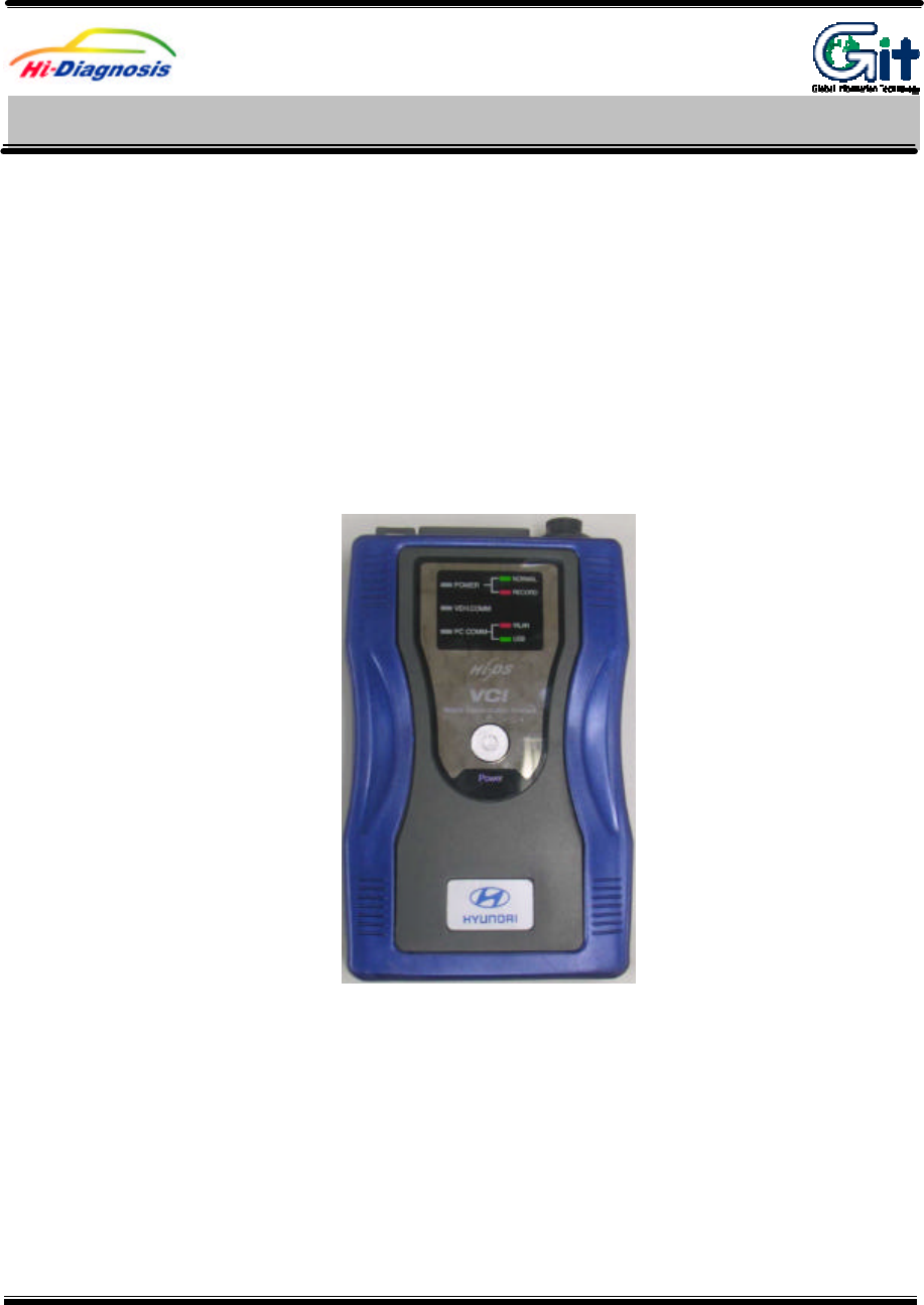
1. VCI Power On
To turn on the VCI equipment, first of all, connect DLC cable from vehicle to VCI module and
depressing the main switch. If diagnosis connector doesn’t applied for 16 pin connector, in other
words, if battery power can’t be supplied from this diagnosis connector to VCI equipment, in this
case, cigar power cable must be connected with cigar connector to supply the battery power with
ACC stage from the ignition switch. In case of using electric supply from cigar power cable, please
connect directly to battery by using battery extension cable.
[Figure 1. Main switch of VCI main module]
1) Confirm the VCI operating condition
VCI equipment has window for checking the VCI operating condition. This window shows that the
condition of each function of VCI by showing with LEDs.
Power on/off and
method of switch operation
H/W understanding for Hi-Diagnosis Module : A–01-005 (p.01)
User’s Manual
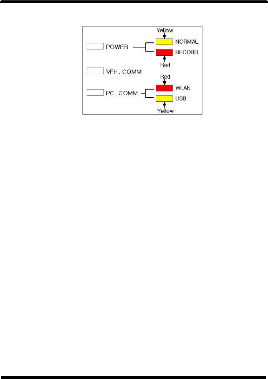
[Figure 2. LED status on window of VCI main module]
① POWER
LED displays with turn VCI equipment on. Color of this LED reflects which function has
been running on VCI equipment either diagnosis or flight record mode. Yellow refers to
diagnosis mode and red is for flight record mode.
② VEH. COMM
The condition of Vehicle Communication can be confirmed by LEDs. It depends on which
function has been selected by user such as monitor DTC, sensor output or actuator
operation by reading the blinking velocity of this LED with keep Vehicle Communication on.
③ PC COMM
As the way of communication between VCI and PC, it also confirmed with displayed LED
color. Red color refers to wireless LAN and yellow is for USB cable.
2. VCI Power Off
To turn off the VCI equipment, depressing the main switch for about 2.5 seconds or disconnecting
the power supply cable. VCI equipment automatically turns off in case of disconnection of power
supply cable.
User’s Manual Module : A-01-005 (p.02)
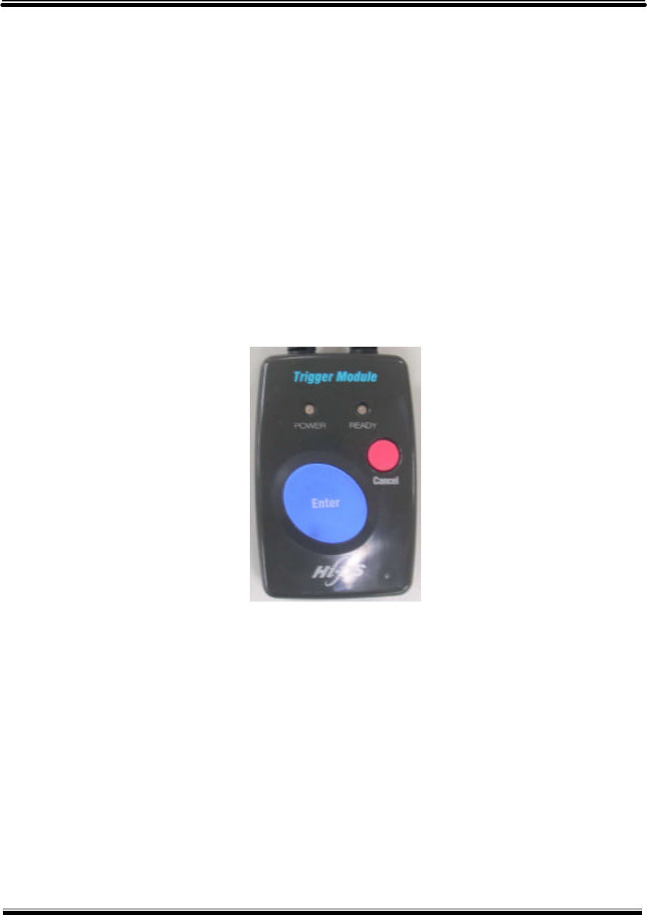
3. Switch operation of trigger module
1) Switch operation of trigger module (Enter / Cancel)
There are buttons for “ENTER” and “CANCEL” on the trigger module. The communication
data is stored into memory of VCI by depressing “ENTER” button during the Flight Record
mode. And the “ENTER” button can be undone by depressing the “CANCEL” button.
2) Lamp of trigger module (Power / Ready)
Trigger module has two different LEDs. The one with red light refers to DC power supplied
condition of VCI module and the other yellow light means recording status of communication
data after depressing “ENTER” button.
[Figure 3. Switches and LEDs of trigger module ]
User’s Manual Module : A-01-005 (p.03)
Trigger module of VCI equipment has two purposes. This trigger module sends the trigger signal
to VCI main module when trouble occurrence. And trigger signal is sent to VCI by depressing the
trigger button with Flight Record mode. According to this trigger signal, the VCI module starts to
store the Flight Record Data. The VCI module receives ON/OFF signal from trigger module. In
other words, trigger module detects ignition switch position and then sends ON/OFF signal to VCI
module. Therefore the VCI module is turned ON/OFF automatically by turning the ignition switch
as driver’s intention. And VCI module finally turns on with the signal from trigger module when
turned ignition switch over the ACC stage. At this moment, VCI prepares for communication with
ECU. The other purpose of trigger module is also supplies DC power to VCI module connected to
the vehicle which isn’t applied for 16 pin(OBD II diagnosis connector) connector.
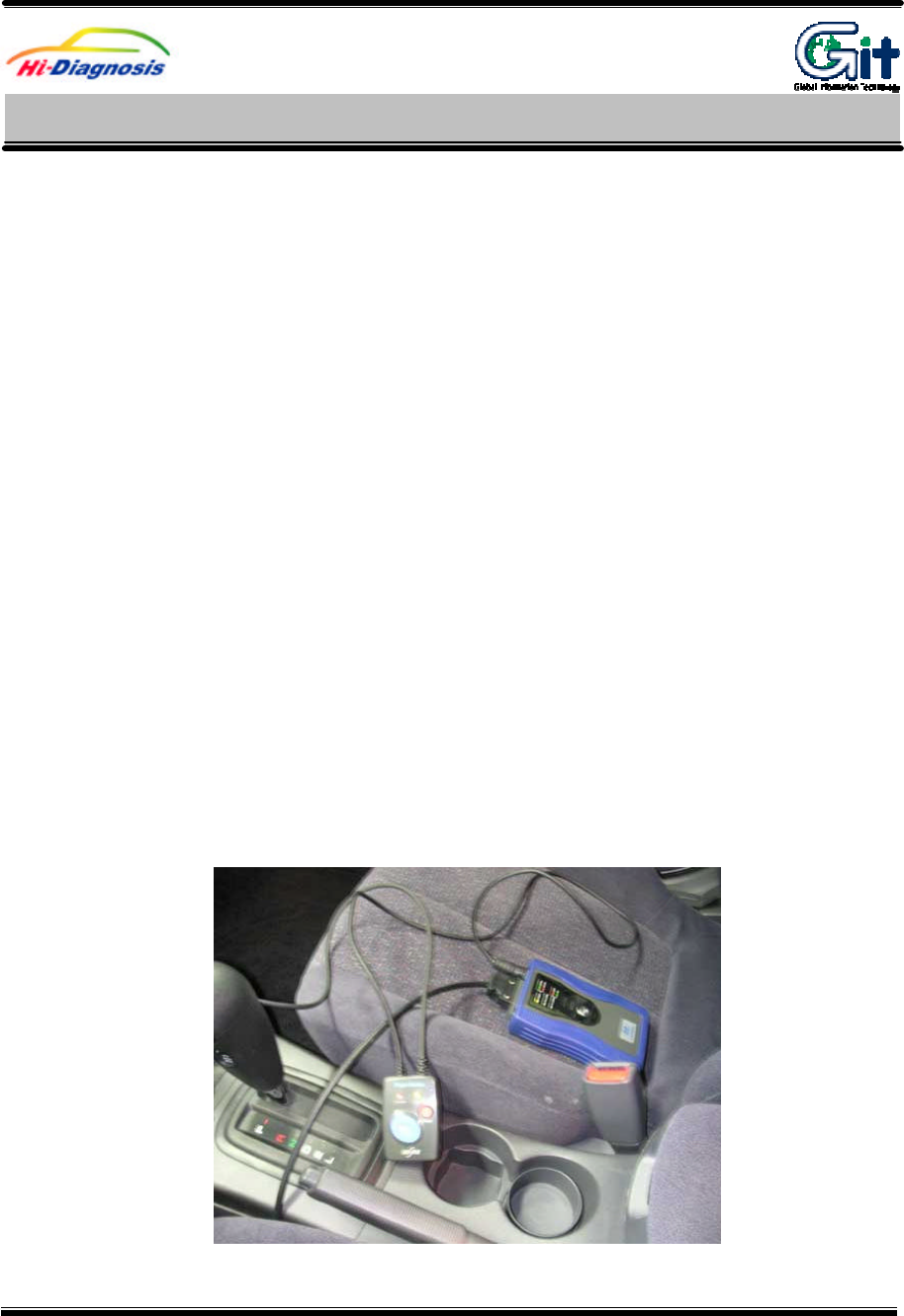
1. Installation of trigger module and cigar power cable
Cigar jack from trigger module and round shape connector with 6pins are each connected with cigar
connector on the vehicle and VCI module. Trigger module must be installed at the certain position to
avoid disturbing their drive and also be considered that data captures promptly and quickly by sending
the signal from trigger module.
[Figure 1. Installation of trigger module]
Installation of trigger module
and cigar power cable
H/W understanding for Hi-Diagnosis Module : A–01-004 (p.01)
User’s Manual
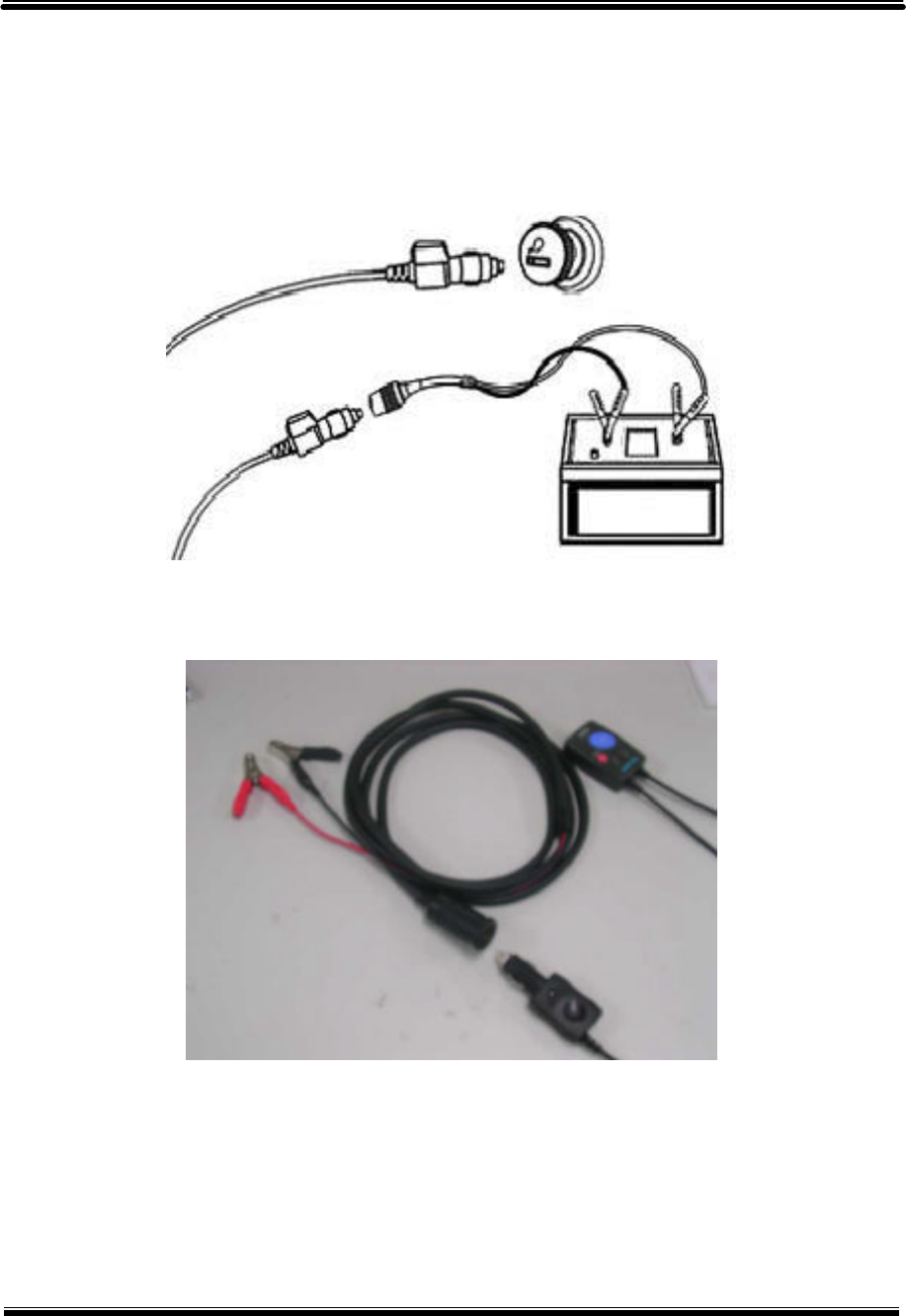
[Figure 2. Connection of cigar jack]
[Figure 3. Connection of battery extension cable]
User’s Manual Module : A-01-004 (p.02)
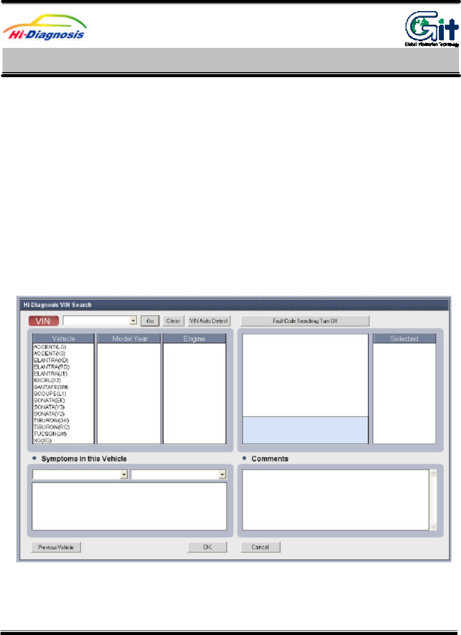
1. Vehicle and Control Module Selection
If “ScanTool” menu item is selected before the vehicle/system selection through VIN selection,
vehicle/system selection window appears as shown in [Figure 1].
Accurate system is necessary for the communication. In Hi-Diagnosis, there is no need to go
through additional vehicle selection after the first selection for the use of other functions.
System selection screen can be divided into 4 main parts: VIN selection, Configuration of
“Scantool” function and “Fault Code Searching” condition, DTC input, and “Comments” input.
[Figure 1. Vehicle Selection]
Scantool-Communication Open and Retry
Hi-Diagnosis program-DIAGNOSIS Module : A –04 –006 (p.01)
User’s Manual
1) VIN Selection
There are three ways to select vehicle.
① By Inputting Vehicle Identification Number consists of 17 figure codes combined by letters and
numbers.
② By selecting vehicle, model year, and engine
③ By using VIN Auto Detect function
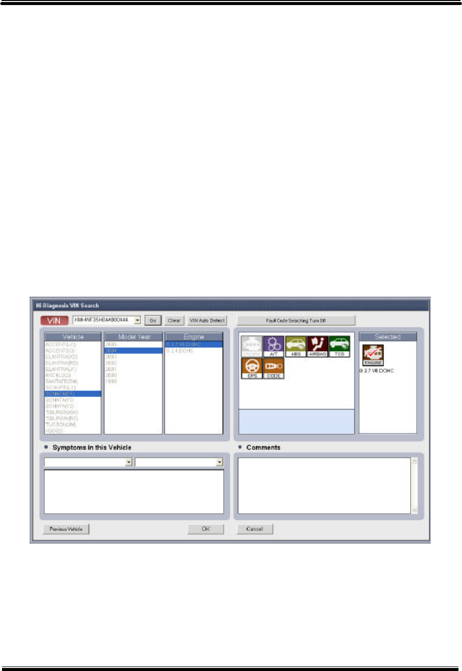
(1) Input of VIN with 17-figure codes combined with number and Letter
There is a way to input all 17-figure code of VIN in the VIN input box. Another way is to input
part of the 17-figure code and choose from the list.
First, input all 17-figure code in the VIN input box and click “Go” button. “Vehicle”, “Model year”,
“Engine” will automatically be chosen. Control modules of the corresponding vehicle appear for
the inputted VIN code.
[Figure 2. VIN Input - All of 17 figures]
Another way is to input part of the 17-figure VIN code and click “Go” button. Window of VIN list
will appear. Choose the corresponding VIN code from the list.
User’s Manual Module : A-04-006 (p.02)
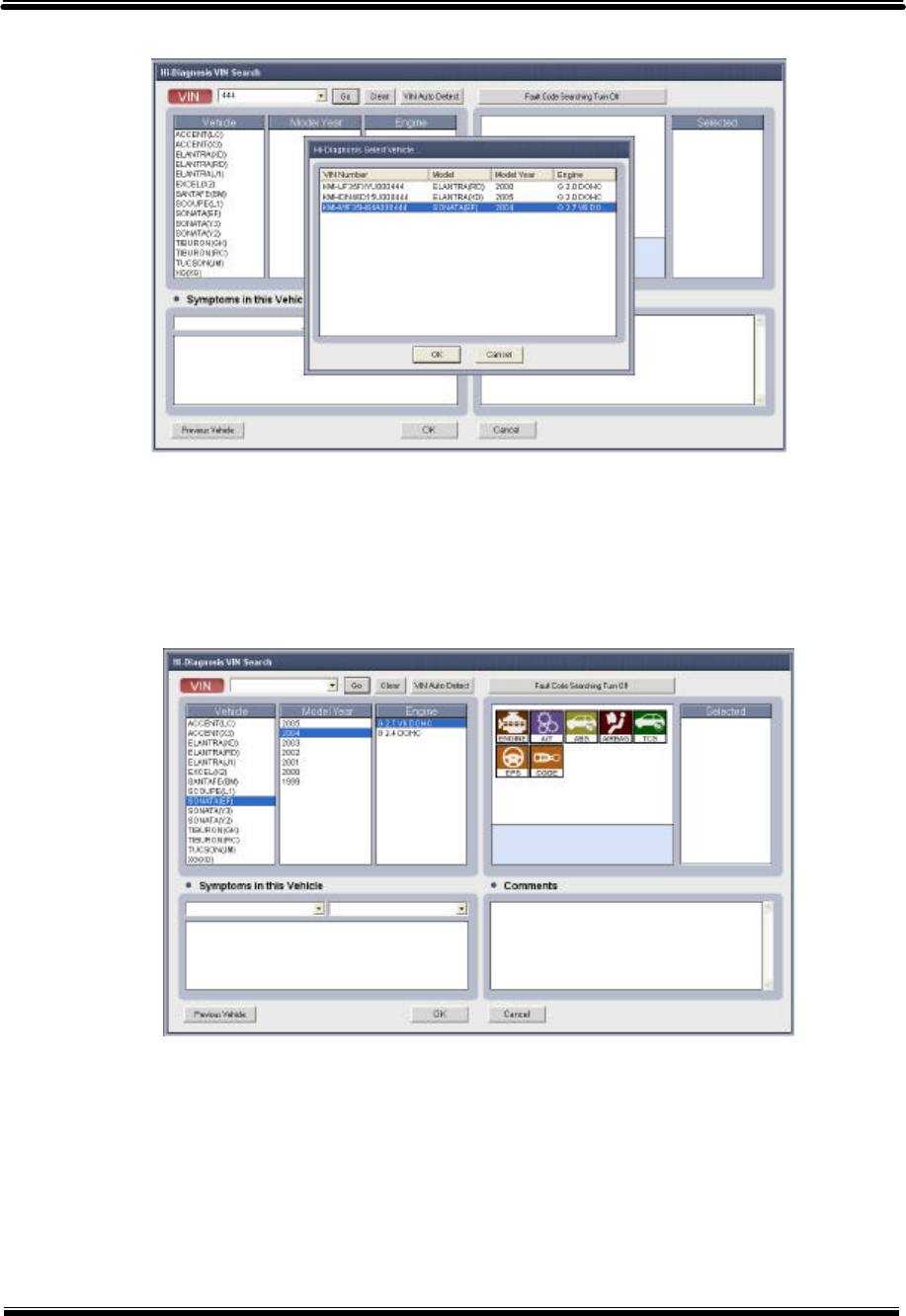
[Figure 3. VIN Input – Part of 17 figures]
(2) Method to select Vehicle, Model Year and Engine
Select “Vehicle”, “Model year”, and “Engine” in each section for a vehicle, and control modules
that can be applied will appear on the window.
[Figure 4. Direct selection for vehicle, Model Year and Engine]
(3) Method to use VIN auto Detect function
If the model year of the selected vehicle is later than 2005 Model Year, then a user can
input VIN code by “VIN Auto Detect” function. Establish a connection to communicate VCI
module with the vehicle (VCI power On, DLC cable, and etc.) and click “VIN Auto Detect”
button to automatically input a VIN code.
User’s Manual Module : A-04-006 (p.03)
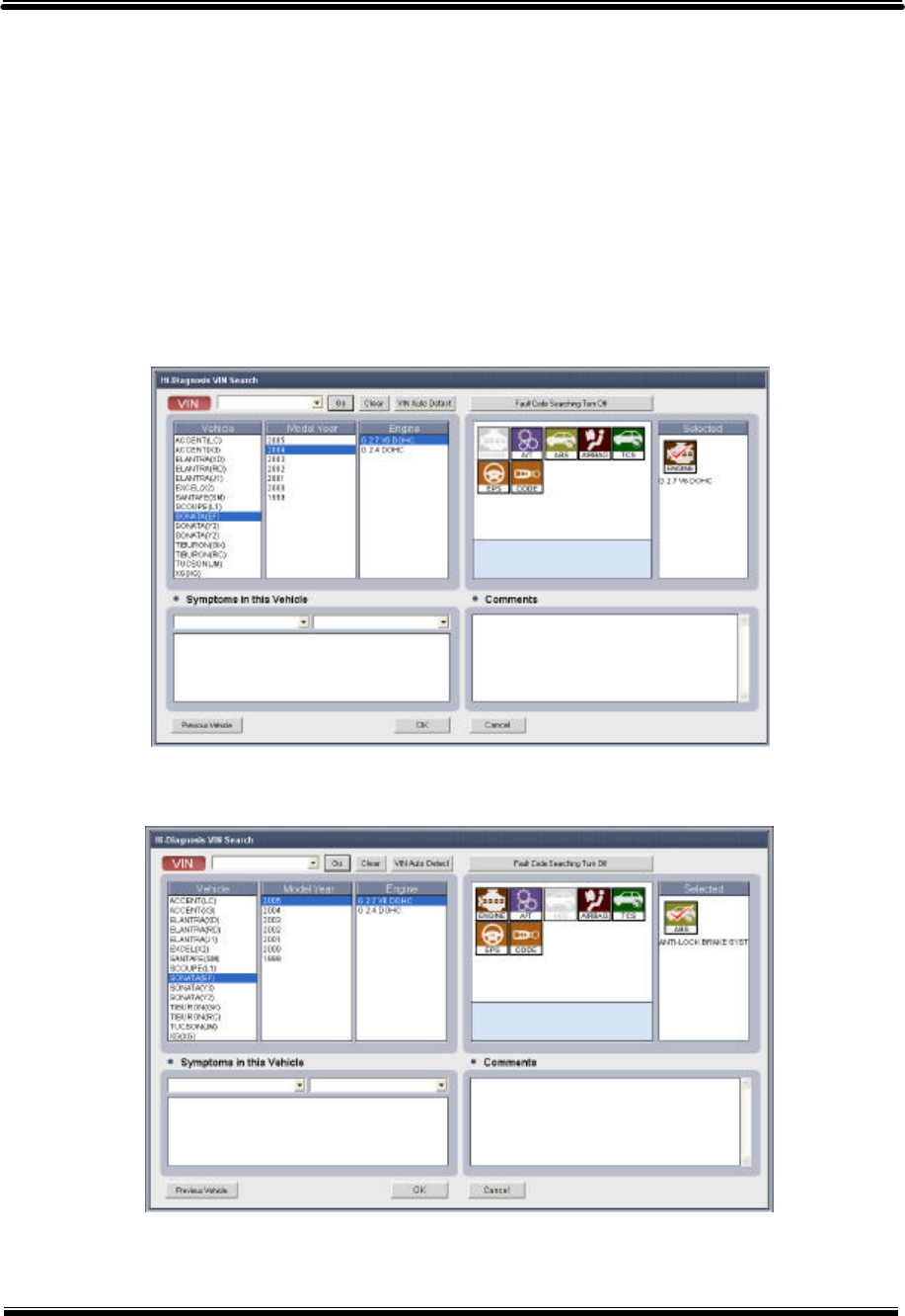
2) Control module selection for scantool and fault code searching
(1) Selection of control module for scantool
By selecting “Vehicle”, “Model Year”, and “Engine” in the “Vehicle Selection”, VCI module for
vehicle communication is selected in the “Selected section” in default, for using “Scantool” function.
Default setting for “Selected” section is always in “Engine”, and user can change to other control
modules. [Figure 5] below shows the state that is set in default as an “Engine”, and [Figure 6]
shows the state that is changed into “ANTILOCK BRAKE SYSTEM”.
[Figure 5. “ENGINE” selection in “Selected” section]
[Figure 6. “ABS” selection in “Selected” section]
User’s Manual Module : A-04-006 (p.04)
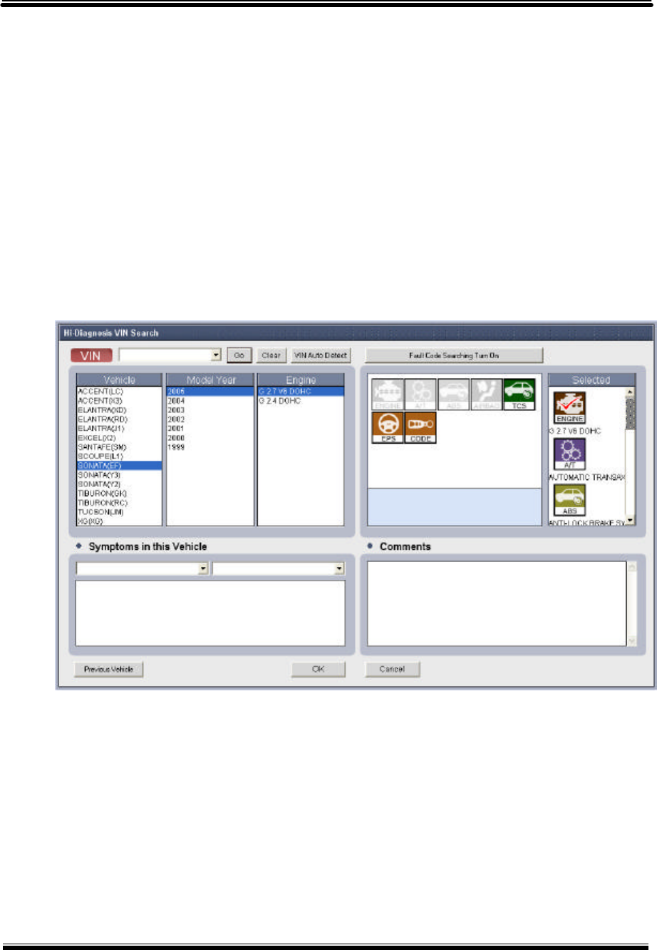
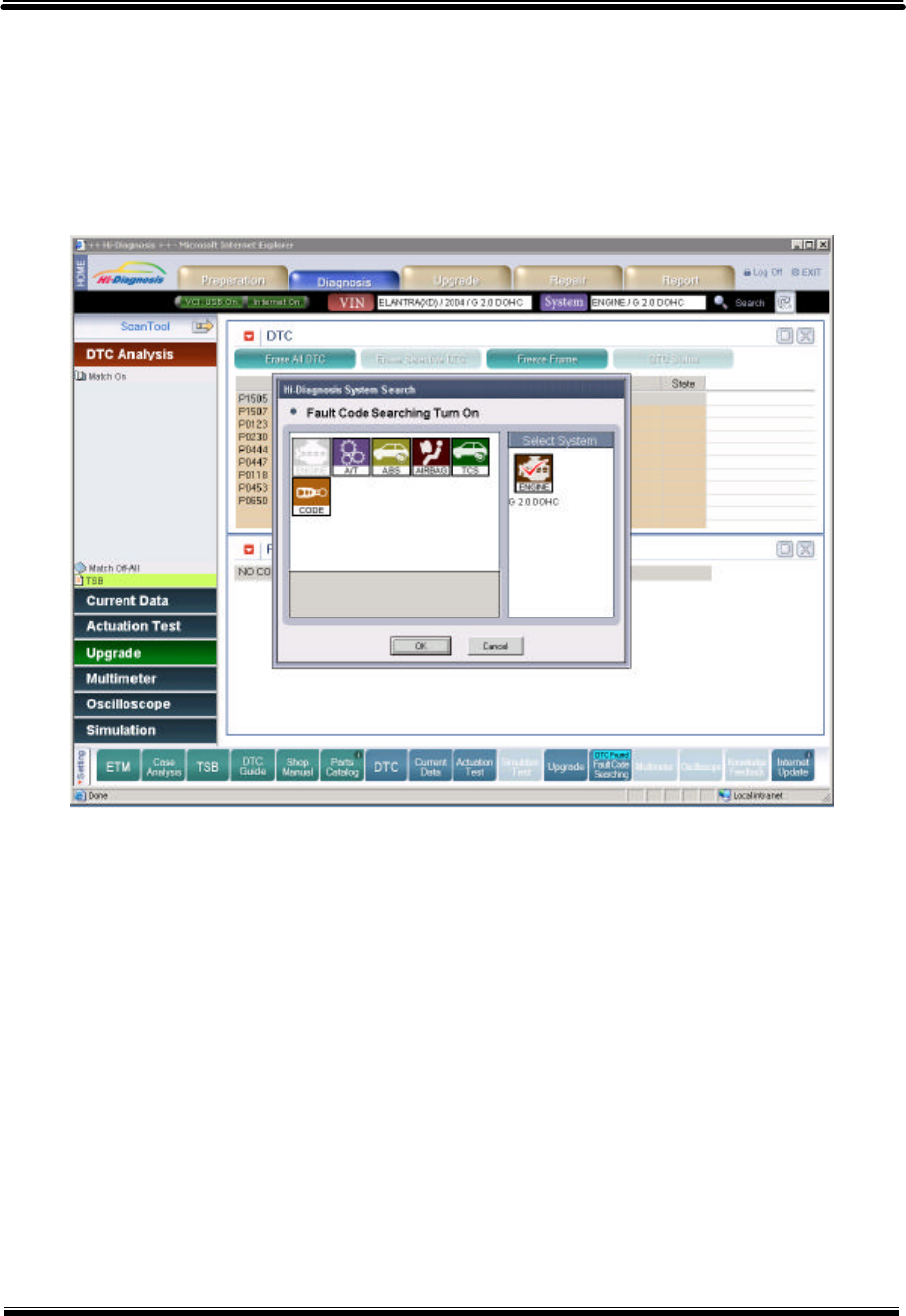
(2) Selection of control module for fault code searching
“Fault Code Searching” function finds DTC automatically for selected control module through
the communication between a VCI and a vehicle. If DTC is found, “By DTC” function on the “Hot
Fix” menu can be effective.
① Control module selection
Click “Fault Code Searching Turn Off” button in order to change to “Turn On” State, for a use
of “Fault Code Searching” function. It is possible to select one or more control module in the
“Selected” section in “Turn On” state. Control Modules that will be applied in “Fault Code
Searching” will move to the “Selected” section by mouse click.
[Figure 7. Control module selection for fault code searching]
② Control module change
In order to modify control modules for “Fault Code Searching” after a move to the “Selected”
section, double click the control module icon in the “Selected” section. The icon will disappear
for the “Selected” section and will move back to the unselected section. It is also possible to add
another module to the “Selected” section. However, at least one control module should be in the
“Selected” section.
User’s Manual Module : A-04-006 (p.05)
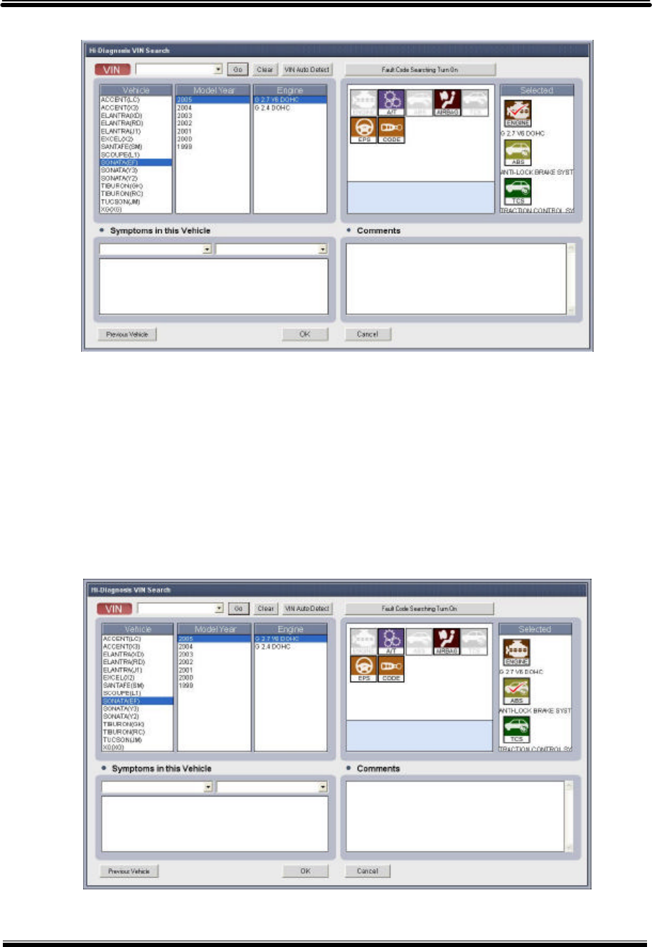
[Figure 8. Control module change]
③ Change of control module for scantool function
Among the control modules in the “Selected” section, it is possible to assign a control module
as a default setting for the communication during the use of “ScanTool” function. The Icon with
the “V” sign on the top, is a default module that will be used for communication. Change in the
default communication module is made through the mouse selection of other control modules.
The “V” sign will appear on the top of the selected module icon.
[Figure 9. Change of control module for scantool function]
User’s Manual Module : A-04-006 (p.06)

(3) Process and result for fault code searching function
By Setting and running “Fault Code Searching” function in the “Vehicle Selection” can
automatically diagnose DTC during the use of other Hi-Diagnosis functions through the
communication between a VCI and a vehicle.
The progress rate for the Fault Code Searching will be displayed on the top of the “Fault Code
Searching” icon, which is located on the lower section of the Hi-Diagnosis screen.
It will be displayed as shown in [Figure 10-1] when there is a communication with the assigned
module. When there is a DTC in any of the module, the icon will be displayed as shown in [Figure
10-2]. DTC list can be checked by clicking the icon in the state of [Figure 10-2].
[Figure 10. Process and result for fault code searching]
[Figure 10-1] [Figure 10-2] [Figure 10-3]
User’s Manual Module : A-04-006 (p.07)
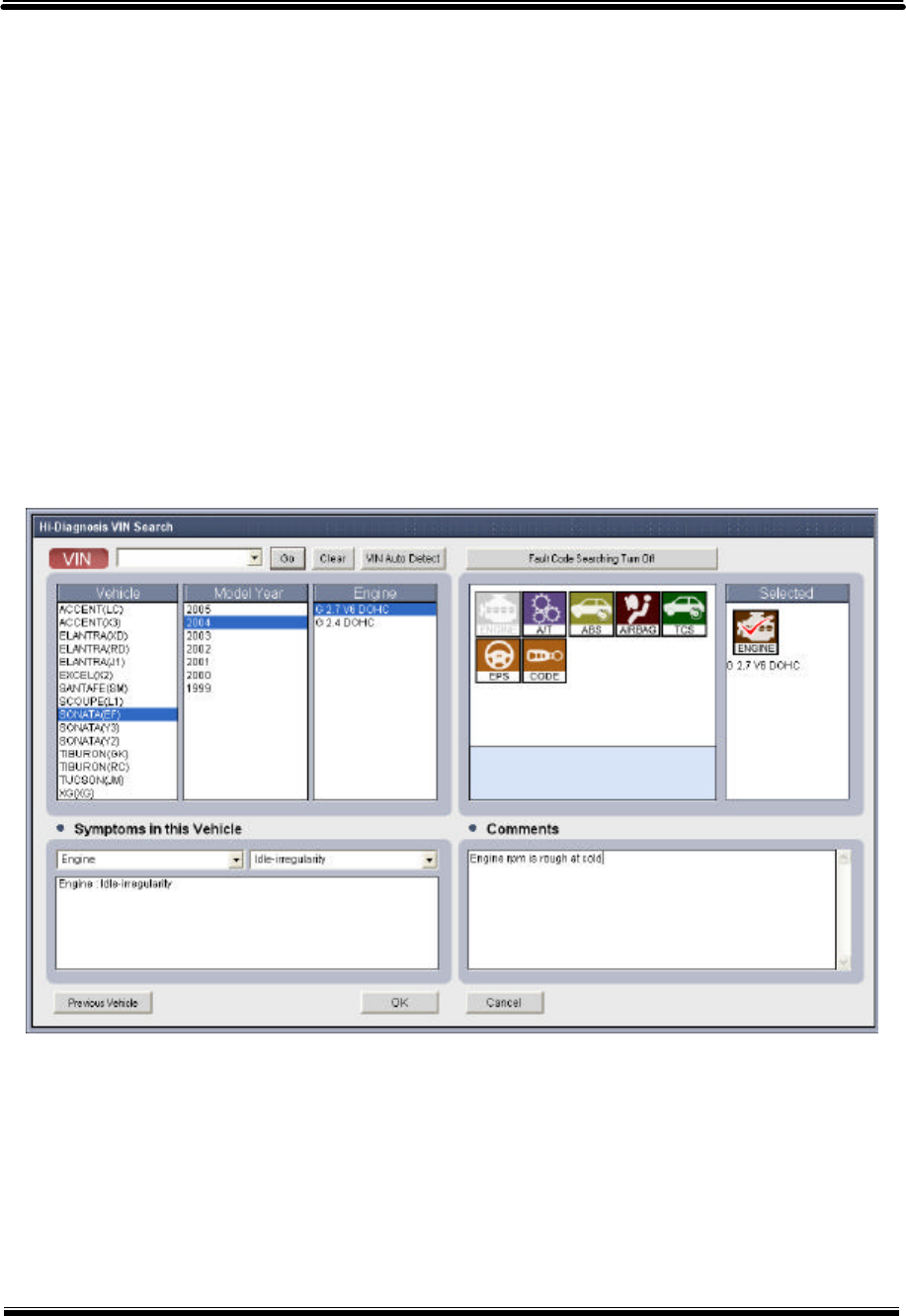
3) Trouble symptoms selection
Select and input vehicle symptom in the “Symptoms in this vehicle” section on the “Vehicle
Selection” window. Selection Menu on the left can be categorized into groups of “Engine”,
“Transmission”, and “Brake”. The right menu is for the selection of symptom for the selected group
on the left. The symptoms are “Hard/No starts”, “Idle-irregularity”, “Engine Stall” and etc.
If there is more than one symptom, it is possible to choose symptoms in addition. Double click
the item to remove from the selected symptoms.
It is possible to use “By Symptom” function in the “Bulletin” menu at the initial page after the
completion of vehicle symptom input. “Symptom Analysis” function in the “Guide Diagnosis” menu
can also be used.
[Figure 11. Input of Symptoms and Comments]
4) Comments Input
“Comment” section in the “Vehicle Selection” window is used when user wants to
comment on the selected vehicle. In case of Vehicle Identification Number (VIN) is
directly inputted in the vehicle selection section, comment will be saved and shown when
the same VIN is selected in the future.
User’s Manual Module : A-04-006 (p.08)
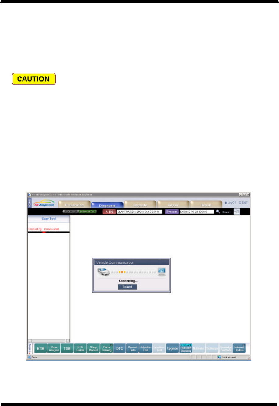
2. Communication Open
If the system selection is completed, the stage to open a communication with the control module
to be diagnosed is necessary for the communication.
Check following matters before opening the communication.
1) Ignition switch of a vehicle should be turned on.
2) DLC cable of VCI should be correctly connected to the DLC connector of the vehicle.
3) VCI module power should be turned on.
4) Connection between the PC and VCI should be stable.
If the communication is opened, the initial page is shown in dual output mode: DTC diagnosis
output and Freeze Frame output.
[Figure 12. Communication Open for selected control module]
User’s Manual Module : A-04-006 (p.09)
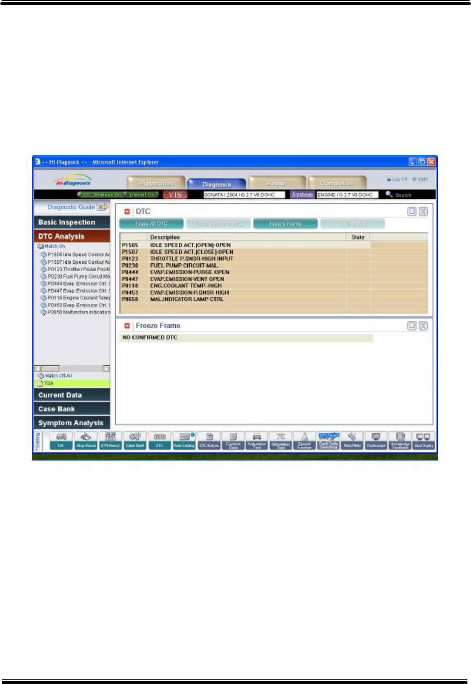
3. Communication Result
After the “Communication Open” communication stays connected if user does not turn off the
VCI nor switches the ignition switch to less than On. If there is a disturbance between the
communication, connection may be lost.
[Figure 13. Result of communication open]
User’s Manual Module : A-04-006 (p.10)
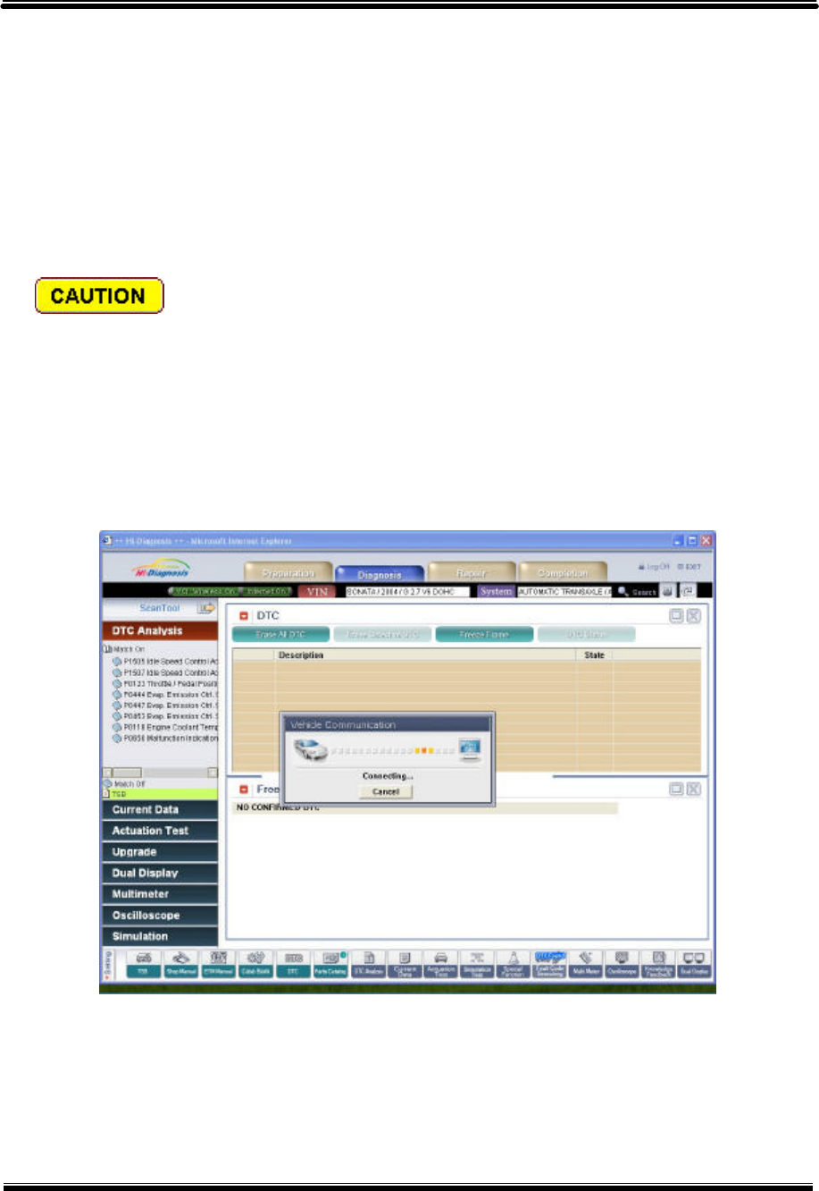
4. Communication Retry
If the communication is lost between the PC and the VCI or the VCI and the Vehicle, it is possible
to retry connection by going back to the initial page and clicking the “Retry” button. “Retry” button
is located in the upper right section of the screen, and retries to make connection for the selected
system control module when it is pressed.
Following matters should be checked before the communication.
1) Ignition switch of a vehicle should be turned on.
2) DLC cable of VCI should be correctly connected to the DLC connector of the vehicle.
3) VCI module power should be turned on.
4) Connection between the PC and VCI should be stable.
[Figure 14. Communication retry for selected control module]
User’s Manual Module : A-04-006 (p.11)
5. Control Module Changing
If user wants to connect in different control module in same vehicle at the current page, reselect
the control module to communicate with system reselect button.
[Figure 15. Control module change]
User’s Manual Module : A-04-006 (p.12)

1. Meeting Hardware Requirements
1) Minimum System Requirements
(1) PC Operation System: above Windows 2000 (IIS (Internet Information Server) eligible OS)
(2) CPU: 500MHz Intel Pentium III Processor or higher microprocessor (or equivalent)
(3) RAM capacity: 256 megabyte (MB) of RAM is recommended minimum.
(4) Hard Disk Capacity: 20GB Hard disk with minimum 5GB of free space.
(5) VGA Card: High Color (65,536 color) and screen resolution of 1024x768, over 2MB
memory.
(6) Peripheral Device: DVD ROM, Keyboard and mouse
2) Recommended System – Panasonic Toughbook CF18
(1) CPU : ① Intel. Pentium. M Processor ULV 718:
② Processor speed 1.1GHz
③ 1MB L2 cache
④ 400MHz FSB
(2) Storage: 60GB HDD
(3) Memory: 512MB SDRAM standard, expandable to 1280MB
(4) Display: 10.4" 1024x768 Tran missive anti-reflective outdoor-readable TFT
(5) Active Matrix Color LCD
(6) Expansion Slot: PC Card Type II x 2 or Type III x 1
(7) Keyboard & Input : ① 82-key with dedicated Windows. key
② Pressure sensitive touch pad with vertical scrolling support
(8) Interface : ① External Video - D-sub 15
② Headphones/Speaker - Mini-jack Stereo
③ Microphone/Line-In - Mini-jack
④ Serial Port - D-sub 9 (Touch screen PC version only)
⑤ USB 2.0 (x2) - 4 pin
⑥ 10/100 Ethernet - RJ-45
⑦ 56K v.92 Modem - RJ-11
Install configuration and
Procedure of Hi-Diagnosis
S/W Understanding for Hi-Diagnosis Module : A–02-001 (p.01)
User’s Manual

(9) Wireless LAN: Intel. PRO/Wireless 2200BG network connection 802.11b+g
(10) Touch screen PC: Microsoft. Windows. XP Professional, Panasonic Handwriting,
Software keyboard
(11) Peripheral device: DVD ROM
User’s Manual Module : A-02-001 (p.02)

2. Install Process for Hi-Diagnosis Software
User’s Manual Module : A-02-001 (p.03)

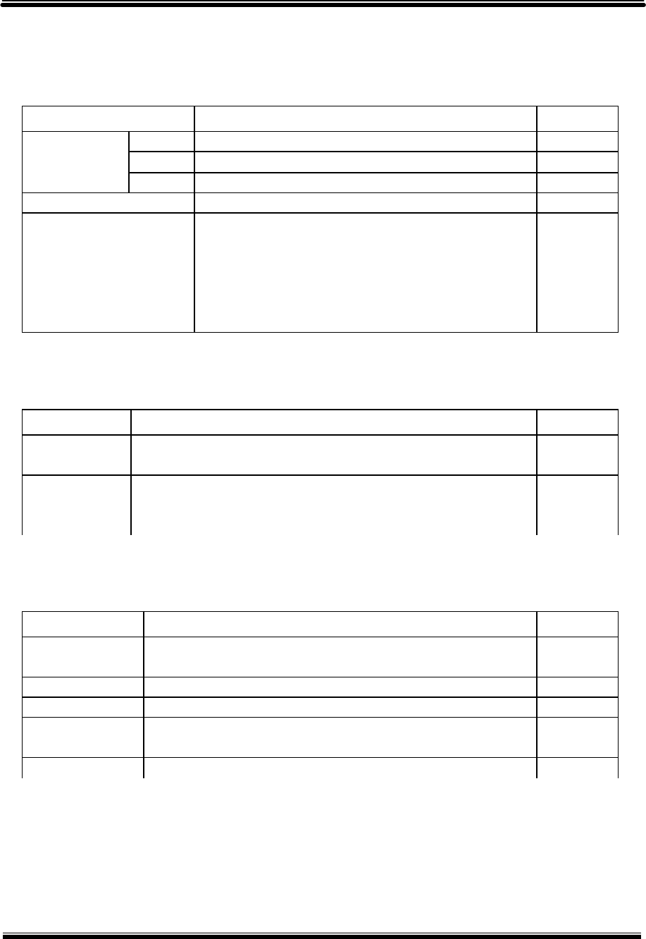
1. Specifications of VCI
1) General features
2) PC Interface
3) Vehicle Communication Interface
Item Specifications Remark
1. Micro Controller ARM9(S3C2410A)@208MHz
2. Memory RAM 8MByte(4BanksX512KbitsX32bit)
ROM 32MByte
3. Operating Voltage
7~35VDC
4. Operating
Temperature 14 ℉~158 ℉ (-10℃ ~ 70℃) : USB Mode
14 ℉~131 ℉ (-10℃ ~ 55℃) : WLAN
5. Operating Mode Diagnosis Function / Flight Record Function
6. Current
Consumption
Typical 350mA @12V
7. Housing ABS & Rubber Shroud
8. Dimension 170 × 102 × 34 mm
9. Weigh 350g
Item Specifications Remark
1. Wire protocol USB 1.1
2. Wireless protocol
Wireless LAN IEEE 802.11b
Item Specifications Remark
1.CAN CAN 2.0B
2.K-Line/L-Line ISO-9141, ISO-9141-CARB, KWP-2000
3.Commercial Veh. SAE-J1708, RS-232C
4.Data/Control Line Melco Pull-Down UART
Specifications and features
H/W understanding for Hi-Diagnosis Module : A–01-002 (p.01)
User’s Manual

4) Added Interface
Item Specifications Remark
1. VSS Vehicle speed simulation
2. Voltage Output 5 ~20 VDC Reprogram booster
User’s Manual Module : A-01-002 (p.02)

2. Specification of Information Terminal
1) Functional Features
Item Specifications Remark
1. CPU Ultra Low Voltage Centrino Pentium M 900MHz
2. Memory 512MB SDRAM (DDR) standard, expandable to 768MB
3. Storage 60GB HDD
4. Display 10.4" 1024 x 768 XGA transreflective, anti-reflective TFT
Active Matrix Colour LCD
5. Keyboard 82-key with dedicated Windows key
6. Pointing Device Pressure Sensing touchpad with vertical scrolling support
7. I/O Ports External Video : D-sub 15
Headphones/Speaker : Mini-jack Stereo
Microphone/Line In : Mini-jack Mono
Modem Integrated 56Kbps V.92 Compliant : RJ11
Network Interface Card 100BASE-TX/10BASE-T : RJ45
Serial Port : D-sub 9 (Touchscreen PC version only)
USB 2.0 (×2) : 4 pin
8. Audio Sigmatel STAC9767 AC-97 v2.1 compliant audio codec
9. PCMCIA Type II x 2
10. Wireless LAN Intel PRO/Wireless 2100 network connection 802.11b
11. Interface Integrated 56K modem
12. Power Supply Lithium Ion Battery Pack (7.4V, 6.6Ah)
13.Operating System Microsoft Windows XP Professional
User’s Manual Module : A-01-002 (p.03)
2) Implemental Features
3) Electrical Features
4) Environmental features
Item Specifications Remark
Height 48.26mm
Width 271.7mm
1. Dimension
Depth 215.9mm
2. Weight 2.0kg(4.4lb)
3. Structure Full Magnesium Alloy Case;
Moisture and dust resistant LCD;
Keyboard and touchpad;
Sealed port and connector covers;
Shock-mounted HDD;
Rugged hinge
Item Specifications Remark
1. AC Input AC 100V-240V 50/60Hz,
Auto Sensing/Switching world-wide power supply
2. Battery Lithium Ion battery pack(7.4V, 660mAh);
Battery operation:4~6hours;
Battery charging time: approximately 3.5 hours/off, 7 hours/on
Item Specifications Remark
1.Temperature Operating : -25 to 60℃ Method 501.4 & 502.4, Proc II
Storage : -50 to 70℃ Method 501.4 & 502.4, Proc I
2. Water/Dust IP54-Dust to 501.4 Proc I and Water to 506.4 Proc III
3. Vibration Method 514.5, Proc I, Category 24
4. Drop 36” drop height onto 2” of plywood, Method 516.5, Proc
IV(Transit Drop Test)
5. Altitude 15,000ft Method 500.4, Proc I & II
User’s Manual Module : A-01-002 (p.04)

FCC NOTICE
THIS DEVICE COMPLIES WITH PART 15 OF THE FCC RULES.
OPERATION IS SUBJECT TO THE FOLLOWING TWO CONDITION:
(1) THIS DEVICE MAY NOT CAUSE HARMFUL INTERFERENCE, AND
(2) THIS DEVICE MUST ACCEPT ANY INTERFERENCE RECEIVED,
INCLUDING INTERFERENCE THAT MAY CAUSE UNDERSIRED
OPERATION.
This equipment has been tested and found to comply with the limits for a Class B
digital device, pursuant to part 15 of the FCC Rules. These limits are designed to
provide reasonable protection against harmful interference in a residential installation.
This equipment generates, uses and can radiate radio frequency energy and, if not
installed and used in accordance with the instructions, may cause harmful interference
to radio communication. However, there is no guarantee that interference will not
occur in a particular installation. If this equipment does cause harmful interference to
radio or television reception, which can be determined by turning the equipment off and
on, the user is encouraged to try to correct the interference by one or more of the
following measures :
- Reorient or relocate the receiving antenna.
- Increase the separation between the equipment and receiver.
- Connect the equipment into an outlet on a circuit difference from that to which
the receiver is connected.
- Consult the dealer of an experienced radio/TV technician for help.
NOTE : The manufacturer is not responsible for any radio or TV interference caused by
unauthorized modifications to this equipment. Such modifications could void the user’s
authority to operate the equipment.