G Lufft Mess Und Regeltechnik Gmbh IPS137 24GHz Radar Sensor User Manual
G. Lufft Mess-Und Regeltechnik Gmbh 24GHz Radar Sensor
user manual
Annex No.5
Users Manual
IPS-137
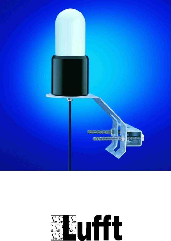
Manual R²S
Radar Rain Sensor
Version V5 (6/2007)

Manual R²S
Table of contents
1 GENERAL REMARKS 3
2 BLOCK DIAGRAM 4
3 OUTPUTS UOUT_1 AND UOUT_2 5
4 COMMISSIONING THE R²S 7
5 CHANGING THE CONFIGURATION 9
6 RS485 PROTOCOL 17
6.1 TELEGRAM SETUP 17
6.2 PHYSICAL CONDITIONS 17
6.3 QUERY OF SENSOR DATA AS A BLOCK (CMD = 0X03) 18
7 DECLARATION OF CONFORMITY 19
Page 2 of 19

Manual R²S
1 General remarks
Nowadays, a precipitation measurement can be based on different principles. In
addition to the classical tipping bucket, the meteorological sector turns more and
more towards differential weight measurement.
The predominant principle in the traffic meteorology is measurement by light barrier.
The new Radar Rain Sensor (R²S) from Lufft works with a 24GHz Doppler radar,
which is used for measuring the speed of precipitation droplets. Based on the
correlation between size and speed of the drops the precipitation quantity is
calculated.
The R²S is characterized by the following features:
• Maintenance free precipitation sensor
• Differentiation of rain / snow
• Determination of quantity (Resolution 1mm, 0.1mm, 0.01mm can be selected)
• Interface: RS485 (half duplex) and 2 digital outputs
• Can be configured for replacing an IRSS88
• Can be configured for replacing tipping bucket systems
Important: Precipitation consisting of tiny rain drops or dry snow are not always
measured reliably due to a very low back-scattering factor.
You may find more technical details in the internet on:
http://www.lufft.com
Page 3 of 19
Manual R²S
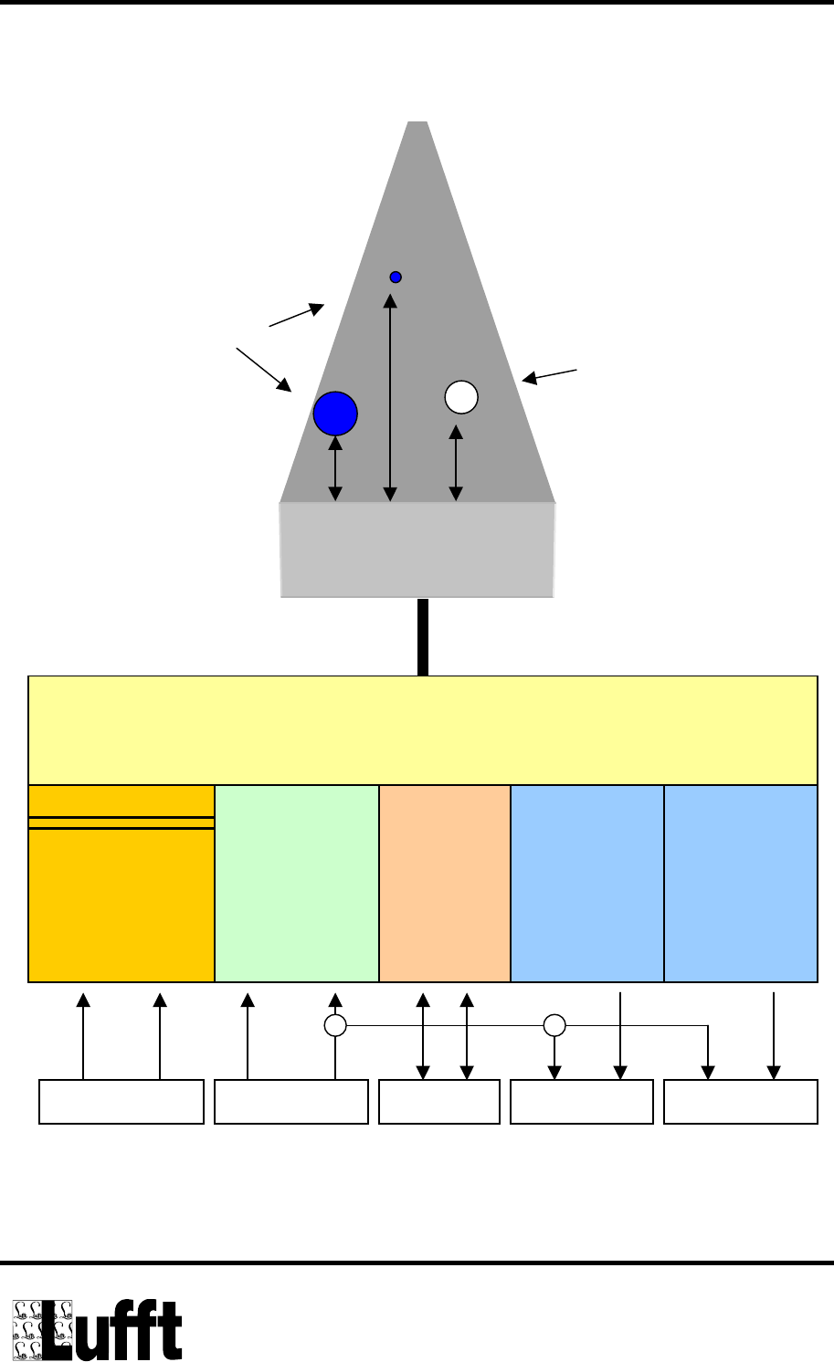
2 Block diagram
Rain
24GHz Radar
Controller
heating
(electrically isolated)
A_heat B_heat
power supply
V+ GND
12V DC
output 2
Uout_2
output 1
Uout_1
RS485 Uout_1 Uout_2
RS485
A B
24V DC
Snow
Page 4 of 19
Manual R²S
3 Outputs Uout_1 and Uout_2
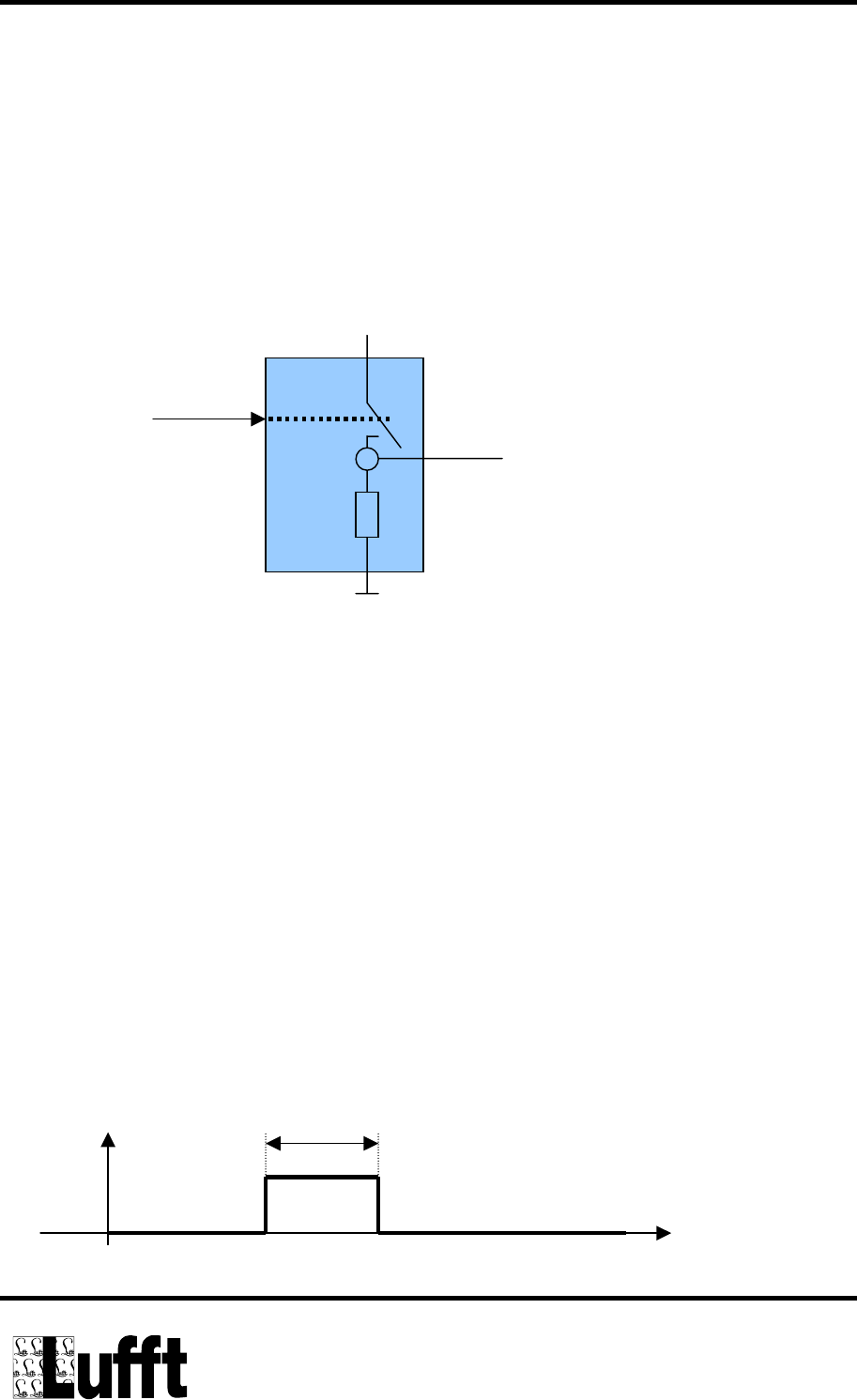
The digital outputs Uout1 and Uout2 are short-circuit protected High Side switches
with integrated pull down resitors.
UB (~ V+)
Controller
Uout_1/2
10k
Fig.: Output Uout_1/2
The functions of the outputs are configured through software.
Possible configurations for Uout1 are:
• Output compatible to IRSS88 (POUT)
• Tipping bucket simulation with a resolution of 1mm
• Tipping bucket simulation with a resolution of 0,1mm (default setting)
• Tipping bucket simulation with a resolution of 0,01mm
The output impuls of the tipping bucket simulation has a length of typically 50ms
50ms
t
Uout_1
Page 5 of 19

Manual R²S
Possible configurations for Uout2 are:
• Output compatible to IRSS88 (SACT)
• State 1:
rain, snowfall = HIGH
no precipitation = LOW.
Every time the accumulated precipitation quantity amounts to 0,01mm, the
output is set to HIGH for 2 minutes. If no precipitation has been detected
for more than two minutes, the output is set to LOW.
• State 2:
In this configuration, output 2 provides a frequency signal so that a
distinction between between rain and snow can be made in an evaluating
unit (e.g. data loggers).
No precipitation = Low
Rain: aprox. 10 Hz
Snow: aprox. 20Hz (default settings).
Important: Changing the configuration can only be done with the
corresponding hard and software (obtainable from Lufft)!
Page 6 of 19

Manual R²S
4 Commissioning the R²S
In the standard version, the R²S is delivered with 10m of lead cable (8 wires)
The following table shows the wire colours, the identification and their meaning:
Identification Colour Meaning
A_Heiz Orange heating, positive, +24V DC/30VA
B_Heiz Brown heating, negative, ground
V+ Red power supply, positive, +12V DC
GND Black power supply, negative, ground
A Yellow RS485, A
B Green RS485, B
Uout_1 Blue output 1, reference potential is GND
Uout_2 Purple output 2, reference potential is GND
Table: R²S cable connection configuration
Connecting the heating element is optional, however necessary if precipitation has to
be measured at temperatures below 5ºC (41ºF). The heating element and power
supply are electrically isolated. All supply lines are protected in case of reversed
polarity. All outpouts are short-circuit protected against the supply voltage.
Page 7 of 19
Manual R²S
Included with the R²S is an angle bracket for a mast/pole mounting. The angle
bracket can be used on masts with diameters from 40mm to 80mm.
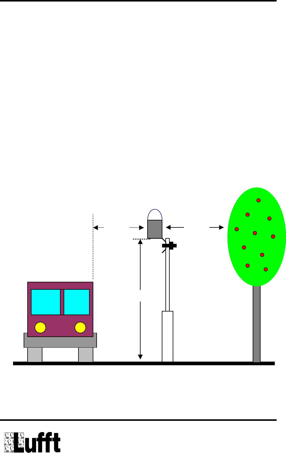
In order to have the R²S function properly, the following mounting conditions must be
fulfilled:
• The R²S should always be mounted on top of the mast in order to avoid
wrong results through shadowing effects.
• No moving objects (trees, bushes, cars etc.) at a distance of 10m around the
sensor.
• Height of the sensor installation >5m.
• Distance to light sources (neon lights, gas discharge lamps, etc.) > 10m.
> 10 m
> 5 m
> 10 m
Page 8 of 19
Manual R²S
5 Changing the configuration
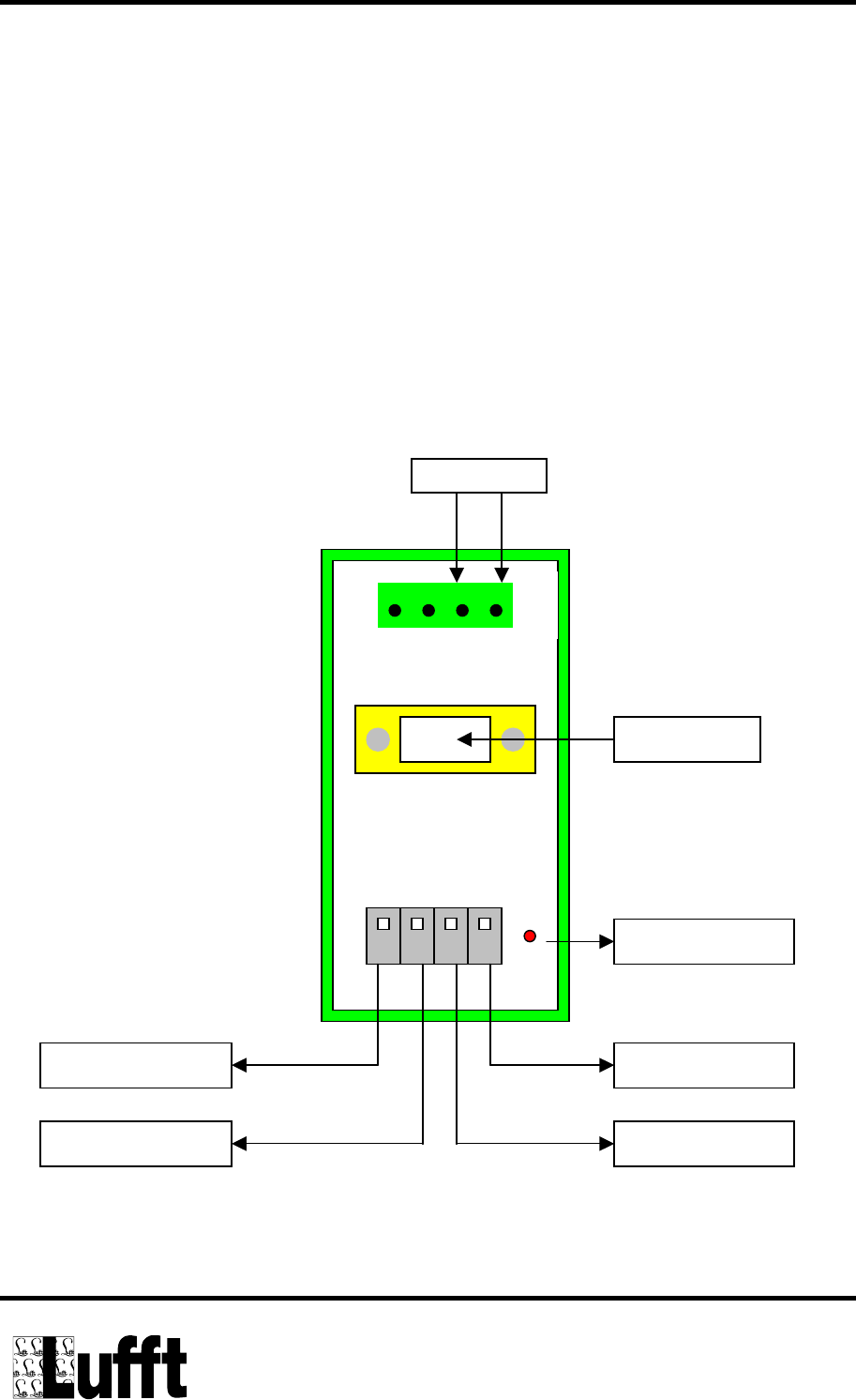
The configuration can be changed through the RS485 interface of the R²S by using a
special software together with a RS232<->RS485 converter.
First connect the R²S to the converter (see illustration). Then link the PC to the
converter with the included RS232 cable. The 12V power supply for the R²S must be
connected to the green plug "POWER". Special must be taken while connecting the
wires (polarity)!
LED
B, green
GND, black A, yellow
V+, red
RS232 to PC
12V DC
Power
-+
Illlustration: Connecting the RS232<->RS485 converter
Page 9 of 19
Manual R²S
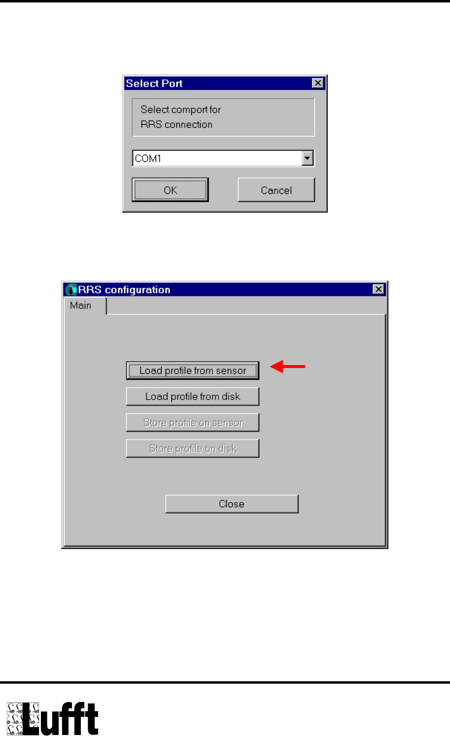
Install the software on your PC and start the program for configuring the R²S.
First, select the serial interface in Configuration -> Communication
Select the RRS configuration in the menu Configuration.
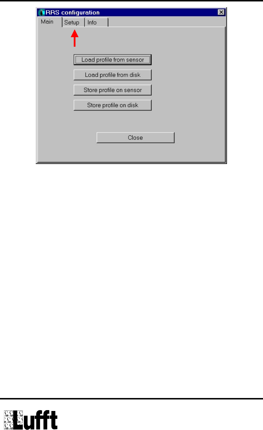
Choose: Load profile from Sensor. The PC will now read the sensor configuration.
The LED on the converter has to light up during this process. After the configuration
has been read successfully, the form on the screen will change and the menu Setup
is presented.
Page 10 of 19
Manual R²S
In case of problems, please check the following points:
• Check the supply voltage on the POWER plug of the converter
• Is the RS232 interface set correctly? (try as well on a different PC, if available)
• Check wire connection of the R²S
Page 11 of 19
Manual R²S
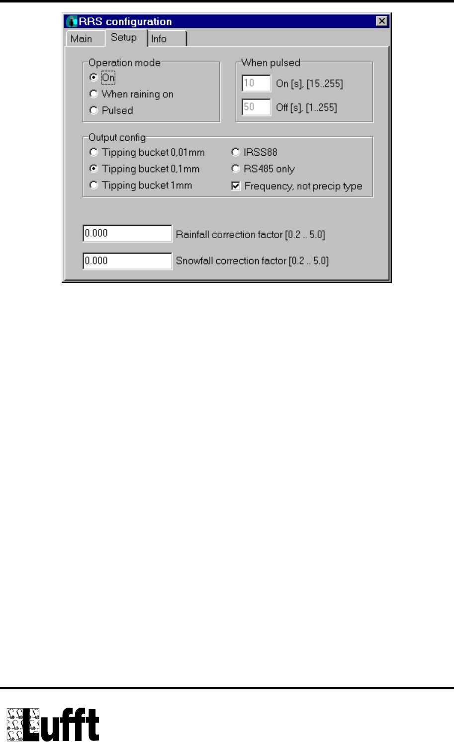
Operation mode:
Apart from the operation mode ON (always on) the R²S supports two further
operation modes which make sense mainly for systems which require low power
consumption (solar systems).
Page 12 of 19
Manual R²S
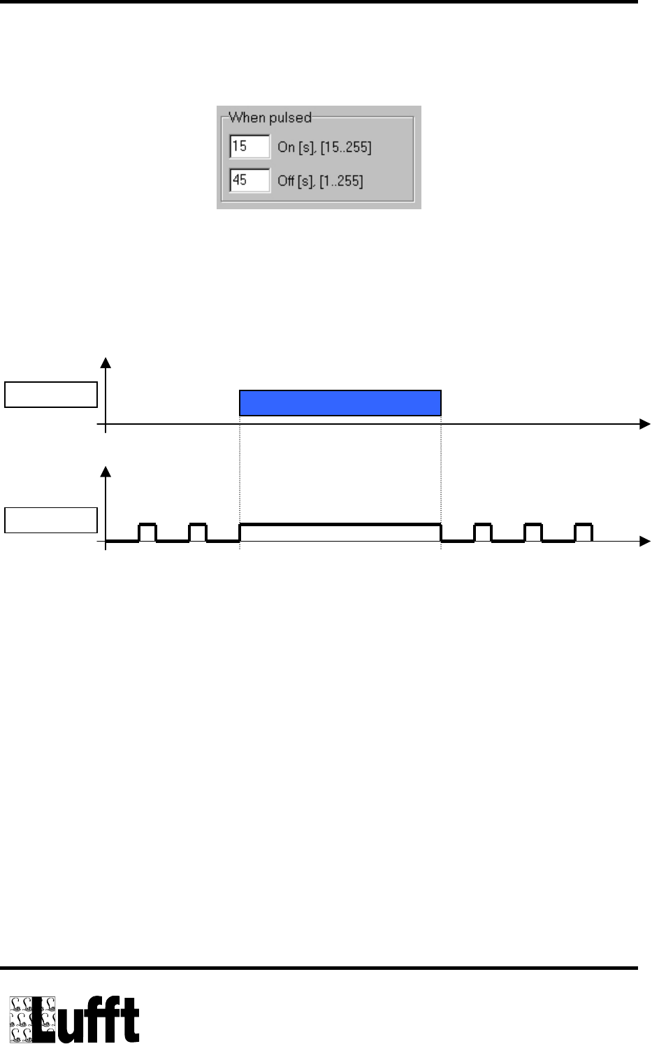
The operation mode „When raining on“ switches the radar sensor on and off for the
duration of the selected intervals in ON and OFF.
If there is any precipitation detected during the regular ON period, the sensor will
remain switched on continuously. When the precipitation ends, the sensor will
automatically return to clock based service. The precipitation quantity which appears
on the output covers the complete ON period.
Precipitation
ON/OFF-R²S t
t
Illustration: Timing Diagram in the “When raining on” mode
Page 13 of 19
Manual R²S
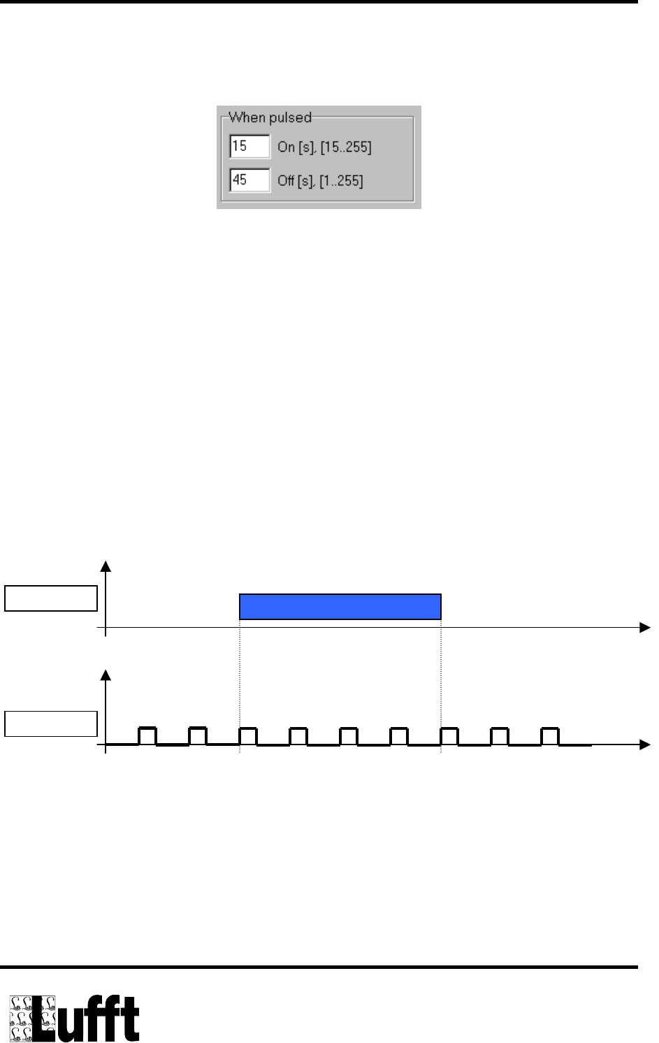
The operation mode „Pulsed“ switches the radar sensor on and off for the duration
of the selected intervals in ON and OFF.
This clock based operation mode works independently from any precipitation
occurring or not. The quantity of precipitation which appears on the output is the
quantity which has been measured during the ON period multiplied with the factor (1+
OFF period / ON period)
Example:
0,2mm are measured during the ON period. The On period lasts 15 seconds, the
OFF period amounts to 45 seconds.
The value on the output is therefore:
0,2mm x (1 + 45s/15s) = 0,8mm
Precipitation
ON/OFF-R²S t
t
Fig.: Timing Diagram in mode “Pulsed”
Page 14 of 19
Manual R²S
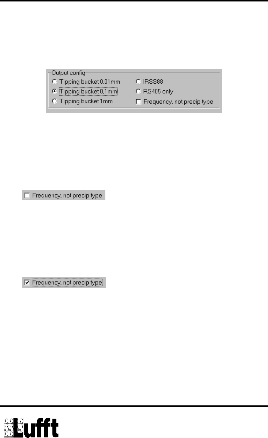
The function of the outputs Uout_1 and Uout_2 is set in the menu „OUTPUT
config“.
For the resolution of the precipitation quantity there are 3 different options availabe
(1.0mm, 0.1mm, and 0,01mm). The quantity will always be output on Uout_1. The
pulse length is aprox. 10ms.
If one of the three possible resolutions is selected, output Uout_2 can assume one of
the following functions:
1.
Uout_2 = LOW corresponds to no precipitation
Uout_2 = HIGH corresponds to rain or snowfall
Every time, the quantity of precipitation reaches 0,01 mm the output is set to
HIGH for 2 minutes. If no precipitation has been detected for more than 2
minutes, the output is set to LOW.
2.
Uout_2 = LOW corresponds to no precipitation.
Uout_2 = Frequency of 10 Hz corresponds to rain
Uout_2 = Frequency of 20 Hz corresponds to snowfall
The frequency signal on the output allows to distinguish between rain and
snow with a corresponding evaluation unit.
When the R²S is used in the IRSS88 mode the function POUT of the IRSS88 is
emulated on the output Uout_1 and the function SACT on the output Uout_2.
Page 15 of 19

Manual R²S
In the operation mode „RS485 only“ both outputs Uout_1 and Uout_2 are set to
LOW. The data can only be read out over the RS485 interface.
Important: The output configuration "RS485 only" will only work in
combination with the operation mode "ON" but does not support the power
saving conditions „When raining on“ or „Pulsed“!
Page 16 of 19

Manual R²S
6 RS485 Protocol
6.1 Telegram setup
descending byte series:
Byte number Meaning Abbr. range
1 Telegram start STX 0x02
2 Identification ID 0 ... 250
3 Length CNT 1 ... 255
4 Command CMD 0 ... 255
5 ... n additional data D0 ... Dn 0 ... 254 Bytes
n + 1
n + 2
Block check CRC_L
CRC_H
16 Bit CRC check sum
from ID until the last Data byte
n + 3 End of telegram ETX 0x03
6.2 Physical conditions
RS485 – 2 wire (half duplex)
Data bits: 8
Stop bits: 1
Parity: none
Baudrate : 19200 Baud (Default setting)
Check sum: 16 Bit CRC from Ident. byte (ID) until the last data byte
CRC-Polynomial: x16 + x12 + x5 + 1 (LSB first) mode
Timeout: Answer from the slave must be available max. 0.5 Sec. after request from
the master
In case of timeout or erroneous answer from the RRS the request from the supplied
PC program is repeated twice max.
Page 17 of 19

Manual R²S
6.3 Query of sensor data as a block (CMD = 0x03)
Master: STX, ID, CNT = 1, CMD = 0x03, CRC_L, CRC_H, ETX
Slave: STX, ID, CNT = x, CMD = 0x03, D0 ... Dn (see table below), CRC_L,
CRC_H, ETX
Slave D0 ... Dn Meaning
D0, D1 Precipitation quantity 0..655,35 mm -> 0..65535
D2 Type of precipitation 0/1/2
D3 Internal use only 0..255
Type of precipitation:
Precipitation quantity = 0mm and D2=0 => no precipitation
Precipitation quantity > 0mm and D2=1 => Rain
Precipitation quantity > 0mm und D2=2 => Snow
Important: On request CMD = 0x03, the sensor provides the accumulated
precipitation quantity, evaluated between the actual and previous request.
Page 18 of 19

Manual R²S
7 Declaration of Conformity
Declaration of EEC Conformity
For the following product
R²S, Order Reference 8367.xx
it is hereby confirmed that they comply with the principal safety requirement which
are set out in the guidelines of the council for the unification of legal regulations of the
member states concerning electromagnetic compatibility (89/336/EEC) and
1999/5/EG.
This declaration is valid for all specimens which are manufactured according to the
current production drawings – which are the component of this declaration.
The manufacturer is responsible for this declaration
Issued by
G.LUFFT
Mess- u. Regeltechnik GmbH
Gutenbergstraße 20
D-70736 Fellbach
Postfach 4252
D-70719 Fellbach
Fellbach-Schmiden, 14.6.2002 Klaus Hirzel
Page 19 of 19

Manual R²S
Declaration of Conformity for USA
This device complies with Part 15 of the FCC Rules. Operation is subject
to the following two conditions:
(1) This device may not cause harmful interference, and
(2) this device must accept any interference received, including
interference that may cause undesired operation.
Usually this is followed by the following FCC caution:
Any changes or modifications not expressly approved by the party
responsible for compliance could void the user's authority to operate this
equipment.
Declaration of Conformity for CANADA
Operation is subject to the following two conditions:
(1) this device may not cause interference, and (2) this device must accept any
interference, including interference that may cause undesired operation of the device.
Usually this is followed by the following RSS caution:
Any changes or modifications not expressly approved by the party
responsible for compliance could void the user's authority to operate this
equipment
Page 20 of 19
Version 6.0 IPM-137 page 1 of 3
2007-05-07
DATA SHEET
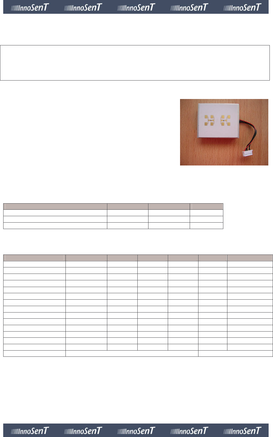
Product Family: K-Band Transceivers
K-Band Transceiver
with two integrated patch antennas, RF- and IF-pre-amplifier
IPM-137 (and variant IPM-137_US)
Description:
-
radar-based motion detector
-
available in different frequency ranges:
IPM-137; ETSI-compliant frequency
IPM-137_US; FCC-compliant frequency
-
advanced PHEMT-oscillator with low current consumption
-
RF-pre-amplifier for lowest noise operation
-
split transmit and receive path for maximum gain
-
mono (single channel) operation
-
IF-pre-amplifier, bandwidth limited for lowest noise
performance
-
compact outline dimensions
Absolute Maximum Ratings:
Parameter Symbol Rating Units
supply voltage V
CC
5.5 V
operating temperature (out of spec) T
OP
- 40 / + 85 °C
storage temperature T
STG
+ 90 °C
Electrical Characteristics:
Parameter Symbol min. typ. max. units comment
transmit frequency f
IPM-137
24.000 24.125 24.250 GHz
f
IPM-137_US
24.075 24.125 24.175 GHz
output power (EIRP) P
out
18 dBm
temperature drift ∆f - 500 kHz/°C
antenna pattern horizontal 65 ° azimuth
vertical 40 ° elevation
side lobe suppression horizontal 15 dB azimuth
vertical 15 dB elevation
IF output voltage offset V
CC
/2 V
IF-amplifier gain 46 dB
bandwidth 50 – 1.5k Hz
supply voltage V
CC
4.75 5.0 5.25 V
supply current I
CC
60 mA IF-amp included
operating temperature T
OP
- 20 + 60 °C
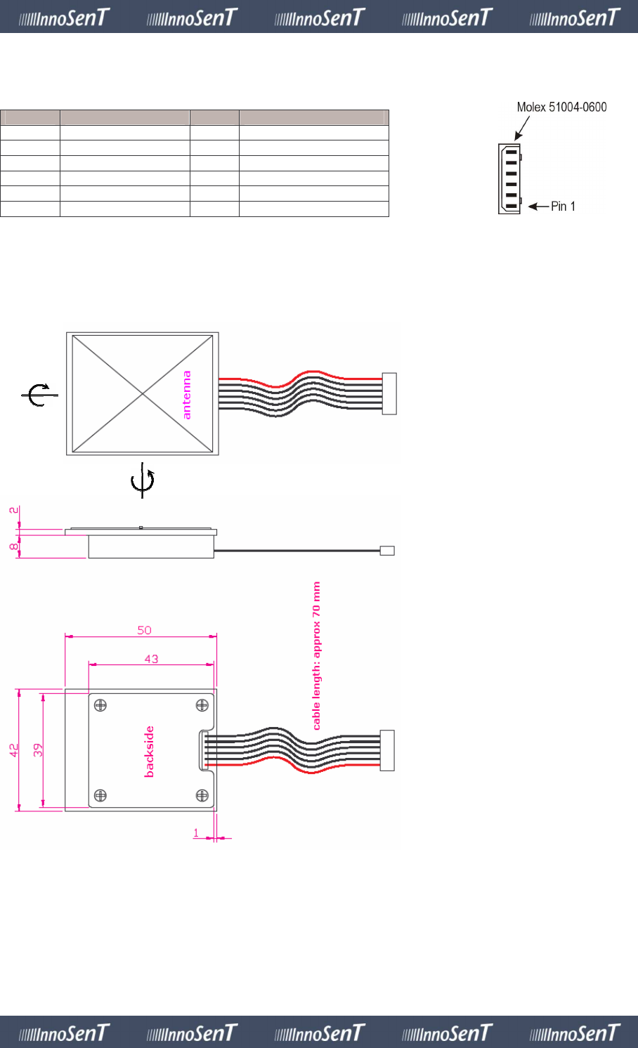
outline dimensions ~ 42 x 50 x 11 compare drawing
Version 6.0 IPM-137 page 2 of 3
2007-05-07
Interface:
The sensor provides a 2 mm pitch 6 pin connector Molex P/N 51004-0600.
Pin # Description In/Out Comment
1 not connected
2 V
CC
input supply voltage (+5 V)
3 GND input analog ground
4 IF1 output signal output
5 not connected
6 not connected
mates with: Molex P/N 53014, 53015 and 53025
Mechanical Outlines:
(dimensions in mm)
azimuth
elevation
Version 6.0 IPM-137 page 3 of 3
2007-05-07
Certification and environment protection:
InnoSenT GmbH has established and applies a quality system for:
Development, production and sales of radar sensors for commercial and
industrial sensors
An audit was performed, Report No. 010350 Proof has been furnished that
the requirements according to DIN EN ISO 9001:2000 are fulfilled.
This InnoSenT product is compliant to the restriction of hazardous substances
(RoHs – European Union directive 2002/95/EG).
InnoSenT Approval
This data sheet contains the technical specifications of the described product.
The technical specifications of this data sheet are approved:
InnoSenT GmbH
Am Roedertor 30
97497 Donnersdorf
GERMANY
Customer Approval
This data sheet contains the technical specifications of the described product. Changes of the specifications must
be in written form. All previous versions of this data sheets are no longer valid.
The technical specifications of this data sheet are approved:
G. Lufft Mess- und Regeltechnik GmbH
Gutenbergstr. 20
70736 Fellbach
____________________________________________
Signature(s)
____________________________________________ company stamp
Name(s)
Contact Information:
InnoSenT GmbH
Am Roedertor 30
97499 Donnersdorf
Germany
Phone: +49 (0) 9528-9518-0
Fax: +49 (0) 9528-9518-99 E-Mail: info@InnoSenT.de
Web: www.InnoSenT.de