G Way Solutions CELLAB25W90 Bi-Directional Booster User Manual FCC ID OIW CBDAESMR1W60
G-Way Microwave / G-Wave Bi-Directional Booster FCC ID OIW CBDAESMR1W60
User Manual
INSTALLATION
AND
OPERATING MANUAL
FOR
BDA-CELLAB-2/25W-90-OA
INDOOR REPEATER

TABLE OF CONTENTS
PARAGRAPH PAGE NO
BDA OVERVIEW 3
BDA BLOCK DIAGRAM DESCRIPTION 3
OPTIONAL EQUIPMENT OVERVIEW 3
BDA BLOCK DIAGRAM DRAWING (Figure 1) 4
ELECTRICAL SPECIFICATIONS 5
MECHANICAL SPECIFICATIONS 6
ENVIRONMENTAL CONDITIONS 6
BDA CONNECTIONS 6
OPTIONAL EQUIPMENT OVERVIEW 7
MECHANICAL OUTLINE DRAWING (Figure 2 & 2a) 8
OPTIONAL BATTERY BACK-UP CONFIGUATION
(Figure 3) 9
BDA INSTALLATION 10
RF EXPOSURE WARNING 10
BDA OPERATION 11
INTERNAL VIEW (Figure 4) 12
CONTROL PANEL ADJUSTMENT (Figure 5) 13
DIAGNOSTICS GUIDE 14
Page 2

BDA OVERVIEW:
The BDA assembly extends the coverage area of radio communications in buildings and RF
shielded environments.
The unit features low noise figure and wide dynamic range. It is based on a duplexed path
configuration with sharp out of band attenuation allowing improved isolation between the
receiving and transmitting paths.
The BDA supports modulation types CDMA and GSM.
BDA CIRCUIT DESCRIPTION:
Refer to figure 1 for the following discussion.
The BDA Downlink path receives RF signals from the base station and amplifies and
transmits them to the subscriber. The BDA Uplink path receives RF signals from the
subscriber and amplifies and transmits them to the base station. The Uplink and Downlink
occupy two distinct frequency bands. For example, the CELLAB frequency bands are as
follows: 824-849 MHz for the Uplink and 869-894 MHz for the Downlink. Two diplexers
isolate the paths and route each signal to the proper amplifying channel.
A selectable Automatic Level Control (ALC) allows for output power limiting. A Manual
Gain Control (MGC) provides continuous control of amplifier gain. The use of these controls
is covered in the “OPERATION” section, later in this document.
Page 3
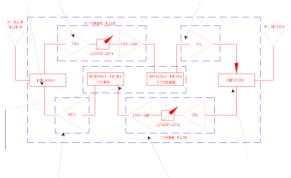
Figure 1
1. 2. 3.
6.
7.
4. 5.
BDA Block Diagram
1. Uplink Diplexer - has low bandpass insertion loss and high selectivity
2. Downlink Pre-amp - is a low noise amplifier that drives the Downlink PA and
offers 46dB Gain
3. Downlink PA – is a power amplifier with an ALC circuit which offers 43dB Gain
4. Uplink MPA – is a medium power amplifier with an ALC circuit which offers 43dB
Gain
5. Uplink Pre-amp - is a low noise amplifier that drives the Uplink MPA and offers
46dB Gain
6. Filters used on High-Gain Repeaters (90dB) to provide better isolation between
Tx & Rx frequencies and to aid the diplexer rejection.
7. Downlink Tx filter is enhanced for High Power applications, preventing arching
when the power amplifier approaches the 1dB compression point.
Page 4

ELECTRICAL SPECIFICATIONS:
Frequency Range
Uplink : 824-849 MHz
Downlink : 869-894 MHz
Pass Band Gain @ min attenuation : 95 dB (Typ.)
Variable Step Attenuator Range : 0-30 dB
(2-dB steps)
Pass band Ripple : ±1.5 dB (typ)
20 dB Bandwidth : 30 MHz (Max.)
Noise Figure @+25°C at max gain : 4.0 dB max.
3rd Order Intercept point
Uplink : +47 dBm (typ)
Downlink : +55 dBm (typ)
Output Power @ 1dB Compression
Uplink : +34 dBm (typ)
Downlink : +44 dBm (typ)
ALC Factory Set Point
Uplink : +27 dBm composite*
Downlink : +37 dBm composite*
*Single carrier CDMA or GSM modulation types
Isolation between Up/Down Link : 110 dB min.
Input/ Output Impedance : 50 Ohms
VSWR (Input/Output) : 1.5: 1 max.
Power Supply : 110VAC/1.4 Amp
: 240VAC/0.7 Amp
: 50 to 60 Hz
*The Manufacturer's rated output power of this equipment is for single carrier operation. For
situations when multiple carrier signals are present, the rating would have to be reduced by
3.5 dB, especially where the output signal is re-radiated and can cause interference to
adjacent band users. This power reduction is to be by means of input power or gain
reduction and not by an attenuator at the output of the device.
Page 5

MECHANICAL SPECIFICATIONS:
Size : 16.0 x 12.0 x 8.75 inch
(406 x 305 x 222 mm)
Weight : 35 Lbs. (16.0kg.) approx.
ENVIRONMENTAL CONDITIONS:
The unit is designed for indoor applications:
Operating temperature: -30°C to + 65°C
Storage temperature: - 50°C to + 90°C
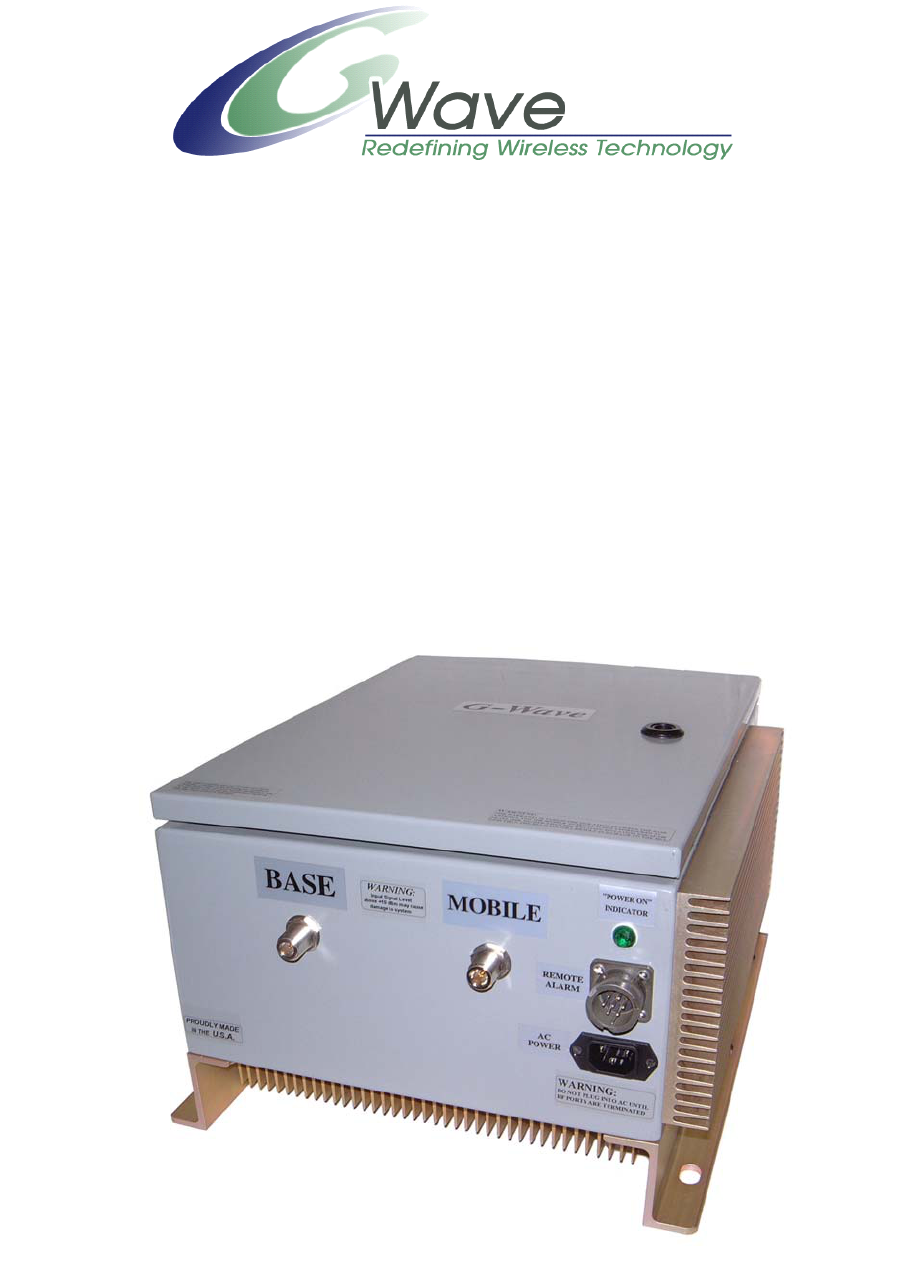
BDA CONNECTIONS
The BDA AC power is accepted through a 3-wire male plug with phase, neutral and ground
leads. The AC power is wired to a high efficiency DC switching power supply which is CE
and UL approved. The power supply runs the amplifiers and the Power On lamp. The metal
enclosure of the BDA is connected to ground.
A 7-pin circular connector provides failure alarm output contacts (see diagrams on page 9) as
well as a 12 VDC (250mA) auxiliary output.
For S1 Option: The BDA is equipped with both AC and DC voltage inputs for power
operation. This gives the flexibility of powering the BDA with either an AC or DC source. If
both sources are connected, the BDA will automatically select the stronger source for power.
NOTE: (To insure that the DC source will be selected when both sources are connected, DC
input voltage must be at least 27 VDC.)
The RF connections are made via two type “N” female connectors. The RF connector labeled
“BASE” must be connected to the antenna pointing towards the base station. The RF
connection labeled “MOBILE” must be connected to the antenna facing the area to be
covered by the BDA.
The RF connections must be made through cables with characteristic impedance of 50 ohms.
The isolation between the base station antenna and the mobile antenna should be at
least 12 dB higher than the BDA gain. Isolation less than this value can cause gain
ripple across the band. Isolation equal to or less than the BDA gain will give rise to
oscillations which will saturate the amplifiers and possibly cause damage to the BDA.
Page 6

OPTIONAL EQUIPMENT OVERVIEW:
a.) Uninterruptible Power System (UPS) Option
An optional UPS is offered for systems that need emergency back-up power. The system can
easily be connected to a battery for uninterruptible operation. Not only does the power supply
power the load, but it also charges the battery. If the AC power fails, the battery will uphold
the load. Batteries can be supplied upon request or a conventional battery configuration can
be used (See Figure 3).
b.) DC Input Power Option (S1)
The BDA is equipped with both AC and DC voltage inputs for power operation. This gives
the flexibility of powering the BDA with either an AC or DC source. If both sources are
connected, the BDA will automatically select the stronger source for power.
Page 7
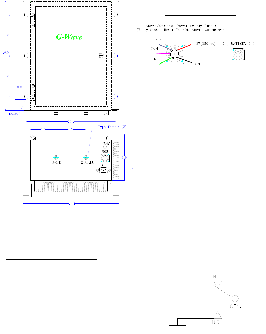
Figure 2
Optional Connectors
BDA Mechanical Outline
Figure 2a
The alarm monitors current of both uplink and downlink
amplifiers. An alarm condition will occur if either uplink or
downlink amplifiers are over or under its current tolerance or if
there is no DC power present.
Optional Alarm Conditions (Relay Shown in Non-Alarm Condition)
Page 8
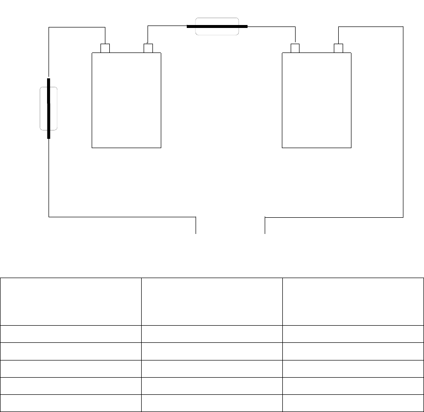
Figure 3
Optional Battery Back-Up Configuration
15 Amp
-
12 Volt
Lead-Acid
Battery
12 Volt
Lead-Acid
Battery
-
+
-
-
+ Battery of
BDA
+
15 Amp Fuse
Battery
Back-Up Time Recommend Battery
Rated Capacity
(20 Hour Rate)
Typical Current Rating
for BDA-XXXX-
1/25W-88
1 Hour 7.2 Amp Hours 3.5 Amps
2 Hours 12 Amp Hours 3.5 Amps
3 Hours 17 Amp Hours 3.5 Amps
5 Hours 28 Amp Hours 3.5 Amps
7 Hours 42 Amp Hours 3.5 Amps
Note: We do not guarantee specifications under Battery Back-Up power.
Page 9

BDA INSTALLATION PROCEDURE
IMPORTANT: DO NOT APPLY A.C. OR DC POWER TO THE BDA
UNTIL CABLES ARE CONNECTED TO BOTH PORTS OF THE BDA
AND THE ANTENNAS.
1. Mount the BDA on the structure with the RF connectors pointing DOWN. Using
appropriate screws and anchors, attach the BDA to the structure using the six mounting holes
on the side flanges.
2. Ensure that the isolation between the donor antenna and the service antenna is at least 12
dB greater than the BDA gain. (Use the higher of the Uplink and Downlink gains
reported on the BDA test data sheet).
3. Connect the cable from the donor antenna to the BDA connector labeled “BASE” and the
cable from the service antennas to the BDA connector labeled “MOBILE”.
4. Open the access door on the BDA and verify that the Uplink and Downlink ALC switches
are in their factory preset “ON” positions and attenuation is positioned to its maximum
setting.
5. Connect the AC power cord to the BDA and then to the power source. Turn the power
switch to its “ON” position. Verify that the “Power On” indicator is lit. Close the access
door.
Installation of the BDA is now complete. To adjust the gain controls to suit the specific
signal environment, refer to “BDA Operation”.
Note: For repeat installations of existing equipment, make sure the ALC switches are in
the “ON” position and attenuation is positioned to its maximum setting (30 dB). After
verification of ALC switches and attenuation, follow the above steps starting with step 1.
RF EXPOSURE WARNING
The antenna used for this transmitter must be fixed-mounted on outdoor permanent
structures. In order to satisfy the FCC RF exposure requirements, the BDA/antenna
installation must comply with the following:
The downlink indoor antenna (Omni type or similar directional antenna) must be installed so
as to provide a minimum separation distance of 0.35 meters (35 cm) between the antenna and
persons within the area. (This assumes a typical antenna with maximum gain of [2 dBi,
VSWR >?> 1.5:1, Zo= 50 ohms, and a cable attenuation of between 2-10 dB)
The uplink outdoor antenna (Yagi type or similar directional antenna) must be installed so as
to provide a minimum separation distance of 0.35 meters (35 cm) between the antenna and
persons within the area. (This assumes a typical antenna with maximum gain of [13 dBi,
VSWR >?> 1.5:1, Zo= 50 ohms, and a cable attenuation of between 2-10 dB).
Page 10
BDA OPERATION
Variable Step Attenuator
BDA gain can be reduced by up to 30 dB in 2 dB steps using the variable step attenuator
(Figure 3). Gain adjustment is made with rotary switches accessible via the access door on
the BDA enclosure. Arrows on the shafts of these switches point to the value of attenuation
selected. BDA gain can be determined by subtracting the attenuation value from the gain
reported on the BDA Test Data Sheet for that side of the unit. The attenuators are labeled for
Uplink and Downlink.
ALC (Automatic Level Control)
To minimize intermodulation products, the Uplink amplifier in the BDA contains an ALC
feedback loop (Figure 4). The ALC circuit senses the output power and limits it to the factory
preset level of +27 dBm on the Uplink and +37 dBm on the Downlink.
ALC function is located within each power amplifier. A red indicator lamp located on each
amplifier illuminates when output power meets or exceeds the ALC set point.
To establish proper operating gain on the Uplink and Downlink sides, start with the
Downlink. Observe the red indicator lamp on the Control Panel. Units are shipping with
maximum attenuation. Decrease attenuation one step at a time until the lamp is lit. Then,
using the Uplink step attenuator, increase the attenuation until the lamp goes off. Repeat the
process for the Uplink. The level indicator is accurate to +/- 0.4 dB of the ALC set point.
Note: Long term operation of the BDA in an alarm condition will void the warranty, and
output power should be immediately reduced using the variable step attenuator.
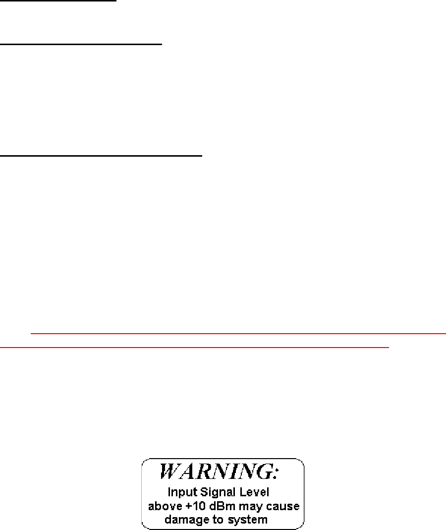
Operation of BDA-CELLAB-2/25W-90-OA at maximum gain with greater than -55
dBm average power incident on the MOBILE port or greater than -45 dBm average
power incident on the BASE port can cause damage to the BDA.
Page 11
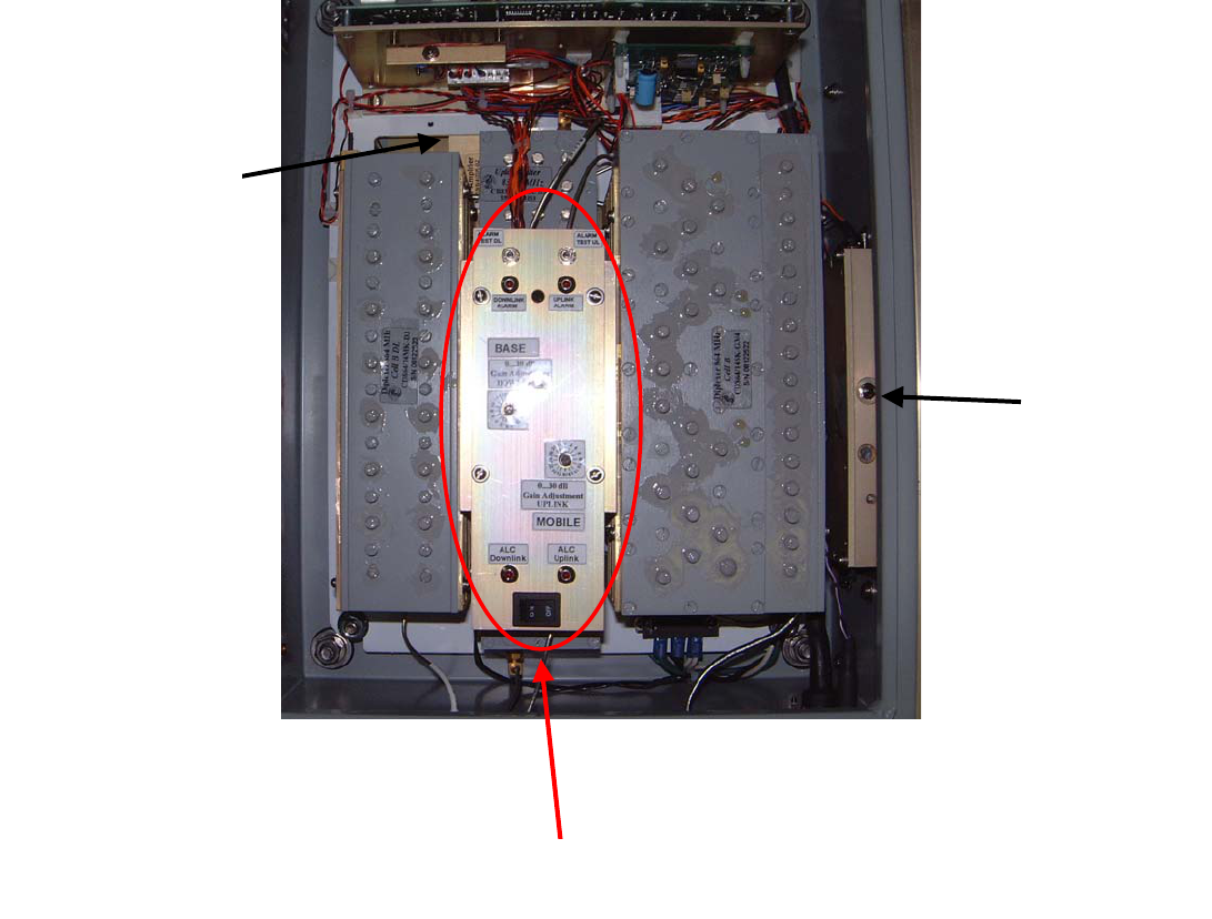
Figure 4
Internal View
Down-Link HPA
Protected for Temperature
Protected for Overload
ALC circuit inside
Up-Link MPA
ALC circuit inside
Control Panel
(See Figure 5)
Page 12
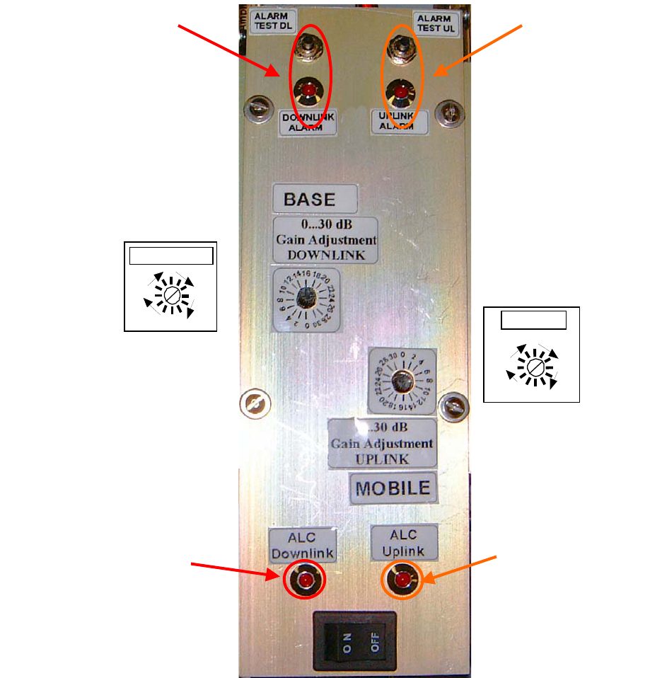
Figure 5
Control Panel Access
Page 13
Uplink ALC LED
Uplink Test
Switch & LED
Downlink Test
Switch & LED
0
D O W NLI NK
0
UPLINK
Downlink ALC LED

DIAGNOSTICS GUIDE
The BDA provides long term, care-free operation and requires no periodic maintenance.
There are no user-serviceable components inside the BDA.
This section covers possible problems that may be related to the installation or operating
environment.
a. Gain Reduction
Possible causes: Bad RF cables and RF connections to antennas, Damaged antennas.
b. Excessive Intermodulation or Spurious
Possible causes:
Amplifier oscillation caused by insufficient isolation. The isolation between two antennas is
given by the equation:
Isolation = 92.5 + 20 Log (F x D) – Gt – Gr
Where:
F = frequency (GHz)
D = separation (Km)
Gt = transmit antenna gain (in the direction of the receive antenna).
Gr = receive antenna gain (in the direction of the transmit antenna).
For example, at the CELLAB frequencies, the antenna isolation at 100 m separation is about
71 dB for omni-directional antennas (0 dB gain). To increase isolation, the antennas should
have higher directivity and must be pointed away from each other.
c. Occasional Drop-out of some Channels
Possible causes: One channel with very strong power dominates the RF output of the
amplifier.
38 Leuning Street
South Hackensack, NJ 07606
Tel. 201-343-3140 Fax 201-343-6390
sales@gwaverf.com
www.gwaverf.com
Page 14