G Way Solutions CELLPCS2W80N RigBooster PRO, Dual Band Outdoor BDA User Manual Manual
G-Way Microwave / G-Wave RigBooster PRO, Dual Band Outdoor BDA Manual
Manual
Installationand
OperatingManual
RigBoosterPRO,DualBandOutdoorBDA
BDA‐CELLAB/PCSF‐2/2W‐80‐OCA1
Page | 2
TABLE OF CONTENTS
PARAGRAPH PAGE NO
BDA OVERVIEW 3
BDA BLOCK DIAGRAM DESCRIPTION 3
OPTIONAL EQUIPMENT OVERVIEW 3
BDA BLOCK DIAGRAM DRAWING (Figure 1) 4
ELECTRICAL SPECIFICATIONS 5
FREQUENCY RANGES (Table 1) 6
MECHANICAL SPECIFICATIONS 7
ENVIRONMENTAL CONDITIONS 7
RF EXPOSURE WARNING 7
BDA CONNECTIONS 8
MECHANICAL OUTLINE DRAWING (Figure 3) 9
CONTROL PANEL CONFIGURATION (Figure 4) 10
BDA OPERATION 11
BDA INSTALLATION 12
DIAGNOSTICS GUIDE 13
Page | 3
BDA OVERVIEW:
The BDA assembly enhances the coverage area of radio communications in buildings
and RF shielded environments.
The unit features low noise figure and wide dynamic range. It is a multi-block system,
based on a dual-duplexed (quadruplexer) path configuration with sharp out of band
attenuation allowing improved isolation between the receiving and transmitting paths,
plus Cellular and PCS paths.
BDA CIRCUIT DESCRIPTION:
Refer to Figure 1 for the following discussion.
The BDA-CELLAB/PCSF-2/2W-80-OCA1 Downlink path receives RF signals from the
base station, amplifies the signal and transmits the signal, without changing the
frequency, into a Distributed Antenna System at the direction of the mobiles. The
signal travels over a DAS medium that then dissipates the signal to the Mobile
subscribers. The BDA-CELLAB/PCSF-2/2W-80-OCA1Uplink path receives RF signals
at the Mobile side from the DAS system, then amplifies it, and transmits the amplified
signal (without changing the without changing the frequency) to the base station. This
Dual Band BDA supports two Uplink and two Downlink, CELL AB and PSC Full
occupy distinct dedicated frequency bands.
For CELL AB Band, the frequency allocations are as follows:
Uplink: 824-849 MHz
Downlink: 869-894 MHz
For PCS Full Band, the frequency allocations are as follows:
Uplink: 1850-1910 MHz
Downlink: 1930-1990 MHz
The Quad-duplexer isolates the paths and route each signal to the proper amplifying
channel.
An Automatic Level Control (ALC) allows for output power limiting. A variable step
attenuator gives 0 – 30 dB of attenuation in 2 dB steps. The use of these controls is
covered in the “OPERATION” section, later in this document..
OPTIONAL OSCILLATION DETECTS INDICATION:
For an added precaution against oscillations from insignificant antenna separation; a
LED indication is inserted into the BDA’s path. This indication will warn the user to
insert additional manual attenuation to eliminate the oscillation.
Page | 4
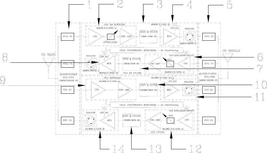
Figure 1
BDA BLOCK DIAGRAM
1. Input Base Quadruplexer – Features low insertion loss and separates UL from DL paths for
CELL and PCS bands.
2. Downlink CELL LNA/Pre-Amp – Low noise figure amplifier with high linearity
3. Selector Filter CELL DL – Features high selectivity and provides required isolation at
maximum gain.
4. Linear Power Amplifier CELL DL – includes ALC circuitry .
5. Output Mobile Quadruplexer – Features low insertion loss and separates UL from DL paths for
CELL and PCS bands.
6. Uplink CELL LNA/Pre-Amp – Low noise figure amplifier with high linearity
7. Selector Filter CELL UL – Features high selectivity and provides required isolation at
maximum gain.
8. Linear Power Amplifier CELL UL – includes ALC circuitry .
9. Downlink PCS LNA/Pre-Amp – Low noise figure amplifier with high linearity
10. Selector Filter PCS DL – Features high selectivity and provides required isolation at maximum
gain.
11. Linear Power Amplifier PCS DL – includes ALC circuitry.
12. Uplink PCS LNA/Pre-Amp – Low noise figure amplifier with high linearity
13. Selector Filter PCS UL – Features high selectivity and provides required isolation at maximum
gain.
14. Linear Power Amplifier PCS UL – includes ALC circuitry.
Page | 5
ELECTRICAL SPECIFICATIONS:
Frequency Range : UL CELL AB 824-849 MHz
: UL PCS 1850-1910 MHz
: DL CELL AB 869-894 MHz
: DL PCS 1930-1990 MHz
Pass Band Gain @ normal operation : 80 dB (Min.)
Variable Step Attenuator Range : 0-30 dB
(2-dB steps)
Pass band Ripple : ±1.5 dB (Typ.)
Noise Figure @+25ºC at max gain : 5.0 dB (Max.)
3rd Order Intercept point
Uplink : +46 dBm (Typ.)
Downlink : +46 dBm (Typ.)
Output Power @ 1dB Compression
Uplink : +34 dBm (Typ.)
Downlink : +34 dBm (Typ.)
Output Power ALC Set Point
Uplink : +27 dBm ±1 dB
Downlink : +27 dBm ±1 dB
Isolation between Up/Down Link : 100 dB (Min.)
Input/ Output Impedance : 50 Ohms
VSWR (Input/Output) : 1.5: 1 (Max.).
Power Supply : 110VAC/0.8 Amp
: 240VAC/0.4 Amp
: 50 to 60 Hz

Page | 6
By adding an additional filter this BDA can support the following bands:
Table 1
Frequency
Band Downlink Frequency
Ranges Uplink Frequency
Ranges
CELL AB 869-894 MHz 824-869 MHz
CELL A 869-880 MHz 824-835 MHz
CELL B 880-894 MHz 835-849 MHz
PCS FULL 1930-1990 MHz 1850-1910 MHz
PCS A 1930-1945 MHz 1850-1865 MHz
PCS B 1950-1965 MHz 1870-1885 MHz
PCS C 1975-1990 MHz 1895-1910 MHz
PCS C-1 1982.5-1990 MHz 1902.5-1910 MHz
PCS C-2 1975-1982.5 MHz 1895-1902.5 MHz
PCS C-3 1975-1980 MHz 1895-1900 MHz
PCS C-4 1980-1985 MHz 1900-1905 MHz
PCS C-5 1985-1990 MHz 1905-1910 MHZ
PCS D 1945-1950 MHz 1865-1870 MHz
PCS E 1965-1970 MHz 1885-1890 MHz
PCS F 1970-1975 MHz 1890-1895 MHz
Page | 7
MECHANICAL SPECIFICATIONS:
Size : 16.0 x 16.0 x 11.2 inch
(406 x 406 x 284.5 mm)
Weight : 35 Lbs. (16.0kg.) approx.
ENVIRONMENTAL CONDITIONS:
The unit is designed for outdoor applications:
Operating temperature: -45ºC to +60ºC
Storage temperature: -50ºC to +90ºC
FCC NOTE:
The Federal Communications Commission (FCC) has tested this product and found it to
comply with their RF Exposure Requirements, pursuant to FCC Part 22 and 24.
IC NOTE:
The Industry Canada (IC) has tested this product and found it to comply with their RF
Exposure Requirements, pursuant to IC RSS-131.
NOTE:
The Manufacturer’s rated output power of this equipment is for single carrier
operation. For situations when multiple carrier signals are present, the rating would
have to be reduced by 3.5 dB, especially where the output signal is re-radiated and
can cause interference to adjacent band users. This power reduction is to be by
means of input power or gain reduction and not by an attenuator at the output of the
device.
RF EXPOSURE WARNING
In order to comply with the FCC RF exposure requirements, the BDA-CELLAB/PCSF-
2/2W-80-OCA1 antenna installation must comply with the following:
Yagi type or similar directional antenna must be installed so as to provide a minimum
separation distance of 30cm (~12 inches) between the antenna and persons within the
area. (This assumes an antenna with gain of 11 dBi, VSWR ≤ 1.5:1, Zo= 50 ohms)
The Omni directional (or leaky cable ) must be installed so as to provide a minimum
separation distance of at least 20cm (~7.9 inches) between the indoor antenna
connected to the RF booster and the human user’s body within the area. (This
assumes an antenna with gain of 0-2 dBi, VSWR ≤ 2:1, Zo= 50 ohms).
BDA CONNECTIONS
The BDA AC power is accepted through a standard 3-wire male plug (IEC-320) with
phase, neutral and ground leads. The AC power is wired to a high efficiency DC switching
power supply, which is CE and UL approved. The power supply runs the amplifiers and
the “Power On” lamp. The metal enclosure of the BDA is connected to ground.
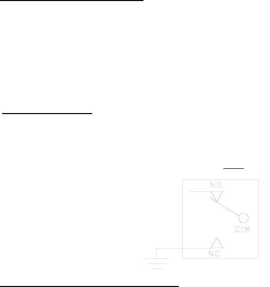
A 7-pin reverse bayonet connector provides failure alarm output contacts (see diagrams
on page 8) as well as a 12 VDC (250mA) auxiliary output.
For S1 Option: The BDA is equipped with both AC and DC voltage inputs for power
operation. This gives the flexibility of powering the BDA with either an AC or DC source. If
both sources are connected, the BDA will automatically select the stronger source for
power. NOTE: (To insure that the DC source will be selected when both sources are
connected, DC input voltage must be at least 27 VDC.)
The RF connections are made via two type “N” female connectors. The RF connector
labeled “BASE” must be connected to the antenna pointing towards the base station. The
RF connection labeled “MOBILE” must be connected to the antenna facing the area to be
covered by the BDA. (Four additional “N” female connectors are included with the
External filter option.)
The RF connections must be made through cables with characteristic impedance of 50
ohms.
The isolation between the base station antenna and the mobile antenna should be
at least 12 dB higher than the BDA gain. Isolation less than this value can cause
gain ripple across the band. Isolation equal to or less than the BDA gain will give
rise to oscillations which will saturate the amplifiers and possibly cause damage to
the BDA.
Page | 8
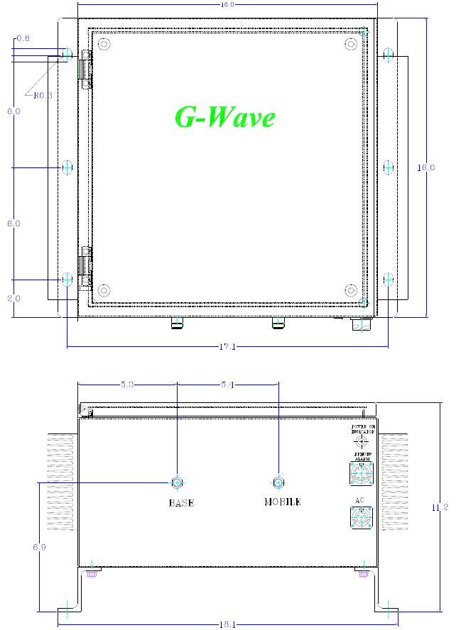
BDA Mechanical Outline
Figure 3
Page | 9
OUTDOOR REPEATER
Cell AB/PCS1900 Full Band
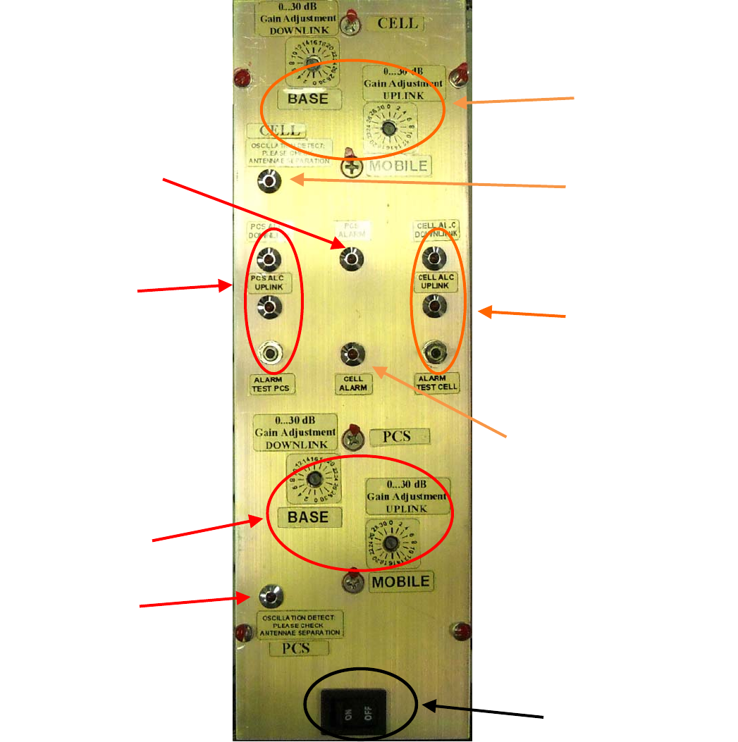
Figure 4
Control Panel
The BDA has two momentary test switches to verify the alarm function. When the
CELL or PCS test switch is depressed the control panel’s CELL or PCS failure LED
will illuminate. The alarm monitors current of both uplink and downlink amplifiers. An
alarm condition will occur if either uplink or downlink amplifiers are over or under its
current tolerance; or if there is no AC present. Two Oscillation detect LED’s will warn
the user to insert additional manual attenuation to eliminate an oscillation. The use of
the ALC controls is covered in the “BDA OPERATION” section, on the next page.
Page | 10
Power Switch
CELL ALC
LED’s
PCS ALC
LED’s
Cellular Uplink &
Downlink Manual
Adjustment
Oscillation Detect
LED
ALARM
PCS
ALARM
CELL
PCS Uplink &
Downlink Manual
Adjustment
Oscillation Detect
LED
BDA OPERATION
Variable Step Attenuator
BDA gain can be reduced by up to 30 dB in 2 dB steps using the variable step
attenuator (Figure 4). Gain adjustment is made with rotary switches accessible via the
access door on the BDA enclosure. Arrows on the shafts of these switches point to
the value of attenuation selected. BDA gain can be determined by subtracting the
attenuation value from the gain reported on the BDA Test Data Sheet for that side of
the unit. The attenuators are labeled for Uplink and Downlink.
Alarm Function
The alarm monitors current of both uplink and downlink amplifiers in each path (PCS
and Cellular). An alarm condition will occur in each path if either the uplink or downlink
amplifiers are over or under its current tolerance or there is no supply power present.
(Relay Shown in Non-Alarm Condition)
ALC (Automatic Level Control)
To minimize intermodulation products, the Uplink and Downlink amplifiers in the BDA
contain an ALC feedback loop. The ALC circuit senses the output power and limits it
to the factory-preset level of +26 dBm. A red indicator lamp located on each the
control panel illuminates when output power meets or exceeds the ALC set point
(Figure 4).
Note: Depending on the BDA’s input signal, the red indicator lamp may not illuminate.
In this case, position the “BASE” antenna in the direction of the closest Base station.
To establish proper operating gain on the Uplink and Downlink sides, start with the
Downlink. Verify that the attenuator is set the maximum position of 30 dB. Observe the
red indicator lamp on the Downlink amplifier. Decrease attenuation one step at a time
until the lamp is lit. Then, using the Downlink step attenuator, increase the attenuation
until the lamp goes off. Repeat the process for the Uplink. The level indicator is
accurate to +/- 0.4 dB of the ALC set point. Note: The recommended operation of
the BDA is when the factory set ALC is turned on. Operation of the BDA in the
alarm condition will void the warranty, and output power should be immediately
reduced using the variable step attenuator.
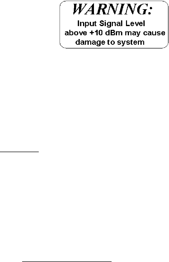
Operation of BDA-CELLAB/PCSF-2/2W-80-OCA1with greater than 0 dBm
average power incident on the MOBILE or BASE ports can cause damage to the
BDA.
Page | 11
Optional Features:
OCAG: Automatic Gain Reduction
When this option is selected, the part number will be changed to BDA-CELLAB/PCSF-
2/2W-80-OCAG. This option protects the BDA from oscillation due to service
upgrades. Should the input RF signal increase due to a service upgrade, the unit will
detect potential oscillation and automatically drop the system’s gain by 30 dB,
preventing interference until a service technician adjusts the system (antenna
separation, location etc.)
Lightning protector
When this option is selected, the part number will be changed to BDA-CELLAB/PCSF-
2/2W-80-OCA2. This option protects the BDA from lightning through the RF BASE
and MOBILE ports.
OUTDOOR BDA INSTALLATION PROCEDURE
Page | 12
IMPORTANT: DO NOT APPLY A.C. POWER TO THE BDA UNTIL CABLES ARE
CONNECTED TO BOTH PORTS OF THE BDA AND THE ANTENNAS.
1. Mount the BDA on the wall with the RF connectors pointing DOWN. Using appropriate
screws and anchors, attach the BDA to the wall at the six mounting holes on the side
flanges.
2. Ensure that the isolation between the donor antenna and the service antenna is at
least 12 dB greater than the BDA gain. (Use the higher of the Uplink and Downlink
gains reported on the BDA test data sheet).
3. Connect the cable from the donor antenna to the BDA connector labeled “BASE” and
the cable from the service antennas to the BDA connector labeled “MOBILE”.
4. Connect the AC power cord to the BDA and then to the power source. Turn the BDA’s
power switch to the “ON” position. Verify that the “Power On” indicator is lit.
*NOTE: Due to the inconsistency of generators in the field, G-Wave recommends
the use of a Power Line Conditioner on the AC source.
Installation of the BDA is now complete.
Page | 13
DIAGNOSTICS GUIDE
The BDA provides long term, carefree operation and requires no periodic maintenance.
There are no user-serviceable components inside the BDA.
This section covers possible problems that may be related to the installation or operating
environment.
a. Gain Reduction
Possible causes: Bad RF cables and RF connections to antennas, damaged antennas.
b. Excessive Intermodulation or Spurious
Possible causes:
Amplifier oscillation caused by insufficient isolation. The isolation between two antennas is
given by the equation:
Isolation = 92.5 + 20 Log (F x D) – Gt – Gr
Where:
F = frequency (GHz)
D = separation (Km)
Gt = transmit antenna gain (in the direction of the receive antenna).
Gr = receive antenna gain (in the direction of the transmit antenna).
For example, at the CELL B frequencies, the antenna isolation at 100 m separation is
about 71 dB for omni-directional antennas (0 dB gain). To increase isolation, the antennas
should have higher directivity and must be pointed away from each other.
c. Occasional Dropout of some Channels
Possible causes: One channel with very strong power dominates the RF output of the
amplifier.