G Way Solutions CELLPCS3380AB Dual Band Bi-Directional Amplifier User Manual
G-Way Microwave / G-Wave Dual Band Bi-Directional Amplifier Users Manual
Users Manual
Installationand
OperatingManual
BDA‐CELLAB/PCSF‐33/33‐80‐AB
DualBandBi‐DirectionalAmplifier
Page | 2
TABLE OF CONTENTS
PARAGRAPH PAGE NO
OVERVIEW 3
BLOCK DIAGRAM DESCRIPTION 3
BLOCK DIAGRAM DRAWING (Figure 1) 4
ELECTRICAL SPECIFICATIONS 5
MECHANICAL SPECIFICATIONS 7
ENVIRONMENTAL CONDITIONS 7
FCC and IC NOTES 7
RF EXPOSURE WARNING 7
CONNECTIONS 8
OPTIONAL FEATURES 8
MECHANICAL OUTLINE DRAWING (Figure 2) 10
INSTALLATION 11
OPERATION 12
FRONT PANEL (Figure 3)
BACK PANEL (Figure 4)
13
13
DIAGNOSTICS GUIDE 14
Page | 3
OVERVIEW:
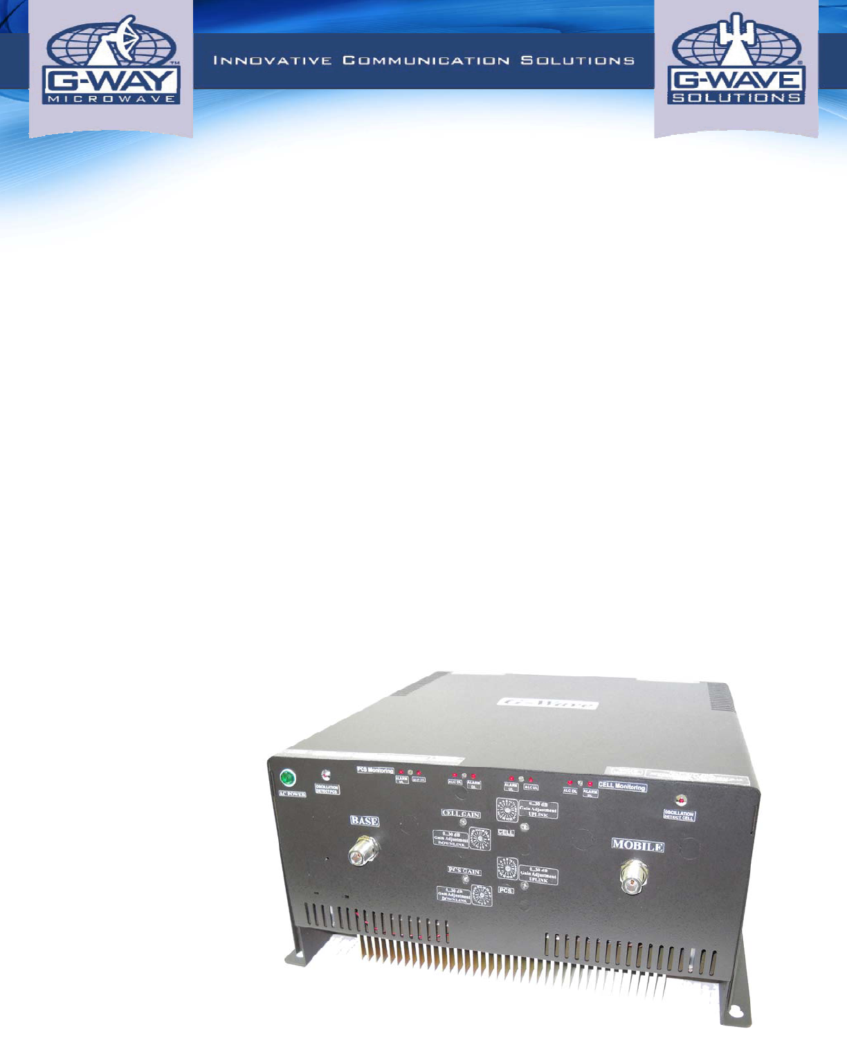
The BDA-CELLAB/PCSF-33/33-80-AB assembly enhances the coverage area of radio
communications in buildings and RF shielded environments.
The BDA-CELLAB/PCSF-33/33-80-AB has dual RF paths (Forward / Reverse) to
improve coverage in two distinct frequency bands.
The unit features low noise figure and wide dynamic range. It is based on a dual
duplexed path configuration with sharp out of band attenuation allowing improved
isolation between the receiving and transmitting paths.
BLOCK DIAGRAM DESCRIPTION:
Refer to Figure 1 for the following discussion.
The BDA-CELLAB/PCSF-33/33-80-AB Downlink path receives RF signals from the
base station, amplifies the signal and transmits the signal, without changing the
frequency, into a Distributed Antenna System at the direction of the mobiles. The
signal travels over a DAS medium that then dissipates the signal to the Mobile
subscribers. The BDA-CELLAB/PCSF-33/33-80-AB Uplink path receives RF signals at
the Mobile side from the DAS system, then amplifies it, and transmits the amplified
signal (without changing the without changing the frequency) to the base station. This
Dual Band BDA supports two Uplink and two Downlink, CELL AB and PSC Full
occupy distinct dedicated frequency bands.
For CELL AB Band, the frequency allocations are as follows:
Uplink: 824-849 MHz
Downlink: 869-894 MHz
For PCS Full Band, the frequency allocations are as follows:
Uplink: 1850-1910 MHz
Downlink: 1930-1990 MHz
The Quad-duplexer isolates the paths and route each signal to the proper amplifying
channel.
An Automatic Level Control (ALC) allows for output power limiting. A variable step
attenuator gives 0 – 30 dB of attenuation in 2 dB steps. The use of these controls is
covered in the “OPERATION” section, later in this document.
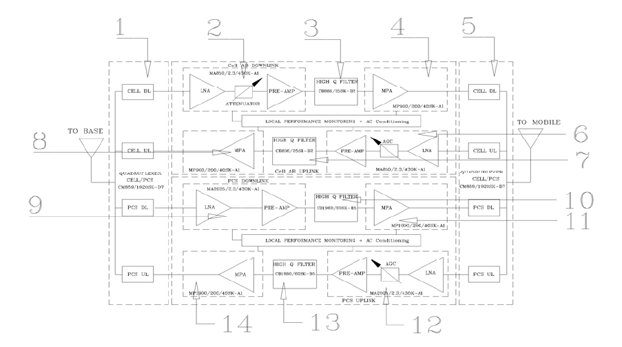
BLOCK DIAGRAM DRAWING:
(Figure 1)
Page | 4
1. Input Base Quadruplexer – Features low insertion loss and separates UL from DL paths for
CELL and PCS bands.
2. Downlink CELL LNA/Pre-Amp – Low noise figure amplifier with high linearity
3. Selector Filter CELL DL – Features high selectivity and provides required isolation at
maximum gain.
4. Linear Power Amplifier CELL DL – includes ALC circuitry and up to 50 dB Gain.
5. Output Mobile Quadruplexer – Features low insertion loss and separates UL from DL paths for
CELL and PCS bands.
6. Uplink CELL LNA/Pre-Amp – Low noise figure amplifier with high linearity
7. Selector Filter CELL UL – Features high selectivity and provides required isolation at
maximum gain.
8. Linear Power Amplifier CELL UL – includes ALC circuitry and up to 50 dB Gain.
9. Downlink PCS LNA/Pre-Amp – Low noise figure amplifier with high linearity
10. Selector Filter PCS DL – Features high selectivity and provides required isolation at maximum
gain.
11. Linear Power Amplifier PCS DL – includes ALC circuitry and up to 50 dB Gain.
12. Uplink PCS LNA/Pre-Amp – Low noise figure amplifier with high linearity
13. Selector Filter PCS UL – Features high selectivity and provides required isolation at maximum
gain.
14. Linear Power Amplifier PCS UL – includes ALC circuitry and up to 50 dB Gain.
Page | 5
ELECTRICAL SPECIFICATIONS:
Frequency Range : UL CELL AB 824-849 MHz
: UL PCS 1850-1910 MHz
: DL CELL AB 869-894 MHz
: DL PCS 1930-1990 MHz
Pass band Gain @ min attenuation : 80 dB (Min.)
Variable Step Attenuator Range : 0-30 dB
(2-dB steps)
Gain Flatness : ±1.5 dB (Typ.)
Noise Figure @+25C at max gain : 5.0 dB (Typ.)
Composite Output Power
Downlink : +33 dBm (Typ.)
Uplink : +33 dBm (Typ.)
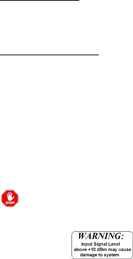
Maximum Input Signal Level :+10 dBm
Input/ Output Impedance : 50 Ohms
VSWR (Input/Output) : <1.5: 1
Power Supply : 110VAC/1.6Amps
: 220VAC/0.8Amps
: 50 to 60 Hz

Page | 6
By additional filtering this BDA can support the following bands:
Table 1
Frequency
Band Downlink Frequency
Ranges Uplink Frequency
Ranges
CELL AB 869-894 MHz 824-869 MHz
CELL A 869-880 MHz 824-835 MHz
CELL B 880-894 MHz 835-849 MHz
PCS FULL 1930-1990 MHz 1850-1910 MHz
PCS A 1930-1945 MHz 1850-1865 MHz
PCS B 1950-1965 MHz 1870-1885 MHz
PCS C 1975-1990 MHz 1895-1910 MHz
PCS C-1 1982.5-1990 MHz 1902.5-1910 MHz
PCS C-2 1975-1982.5 MHz 1895-1902.5 MHz
PCS C-3 1975-1980 MHz 1895-1900 MHz
PCS C-4 1980-1985 MHz 1900-1905 MHz
PCS C-5 1985-1990 MHz 1905-1910 MHZ
PCS D 1945-1950 MHz 1865-1870 MHz
PCS E 1965-1970 MHz 1885-1890 MHz
PCS F 1970-1975 MHz 1890-1895 MHz

Page | 7
MECHANICAL SPECIFICATIONS:
Size : 18.1x 13.2 x 16 inch
RF Connectors : N-Type Female
Weight : 65 Lb. (28.5 kg) approx.
ENVIRONMENTAL CONDITIONS:
The unit is designed for indoor applications:
Operating temperature: - 20°C to + 50°C
Storage temperature: - 50°C to + 90°C
FCC NOTE:
The product has been tested and found to comply with the Federal Communications
Commission (FCC) RF Exposure Requirements, pursuant to FCC Part 22 and 24.
IC NOTE:
The product has been tested and found to comply with the Industry Canada (IC) RF
Exposure Requirements, pursuant to IC RSS-131.
NOTE:
The Manufacturer’s rated output power of this equipment is for single carrier
operation. For situations when multiple carrier signals are present, the rating would
have to be reduced by 3.5 dB, especially where the output signal is re-radiated and
can cause interference to adjacent band users. This power reduction is to be by
means of input power or gain reduction and not by an attenuator at the output of the
device.
RF EXPOSURE WARNING:
In order to comply with the FCC RF exposure requirements, the BDA-CELLAB/PCSF-
33/33-80-AB antenna installation must comply with the following:
Yagi type or similar directional antenna must be installed so as to provide a minimum
separation distance of 60cm (~24 inches) between the antenna and persons within the
area. (This assumes an antenna with gain of 11 dBi, VSWR ≤ 1.5:1, Zo= 50 ohms)
The Omni directional (or leaky cable ) must be installed so as to provide a minimum
separation distance of at least 25cm (~10 inches) between the indoor antenna
connected to the RF booster and the human user’s body within the area. (This
assumes an antenna with gain of 0-2 dBi, VSWR ≤ 2:1, Zo= 50 ohms).

Page | 8
CONNECTIONS:
The BDA AC power is accepted through a standard 3-wire male plug (IEC-320) with
phase, neutral and ground leads. The AC power is wired to a high efficiency DC switching
power supply which is CE and UL approved. The power supply runs the amplifiers and
the LED indicators. The metal enclosure of the BDA is connected to ground.
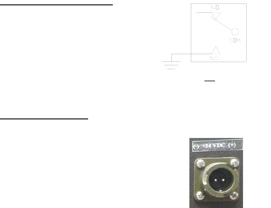
A 9-pin circular connector provides failure and Oscillation Detect alarms output dry
contacts, Normally Open and Normally Closed (see diagrams on page 8).
The RF connections are made via two type “N” female connectors. The RF connector
labeled “BASE” must be connected to the antenna pointing towards the base station.
The RF connection labeled “MOBILE” must be connected to the antenna / passive
DAS facing the area to be covered by the BDA.
The RF connections must be made through cables with characteristic impedance of
50 ohms.
The isolation between the base station antenna and the mobile antenna should
be at least 12 dB higher than the BDA gain. Isolation less than this value can
cause gain ripple across the band. Isolation equal to or less than the BDA gain
will give rise to oscillations which will saturate the amplifiers and possibly
cause damage to the BDA.
Optional Features:
OCAG: Automatic Gain Reduction
This option protects the BDA from oscillation due to service upgrades. Should the
input RF signal increase due to a service upgrade, the unit will detect potential
oscillation and automatically drop the system’s gain by 30 dB, preventing interference
until a service technician adjusts the system (antenna separation, location etc.)
ODSC / ODSCRM7
To minimize interference with other RF systems, this unit includes an Oscillation
detection module that continuously monitors the BDA operation, in a case of
Oscillation detection inside the BDA, the detector will shut down all the amplifiers to
avoid RF interference with other systems in the area, when the Oscillation condition
passes or is resolved, the ODSC operation will turn on all the amplifiers, returning to
regular operation. The ODSCRM7 module will allow Oscillation detect / display &
shutdown of all amplifiers with remote monitoring via 9-Pin connector. A red LED
located on the front panel (see figure 3) illuminates when OSC is detected.
OPTIONAL ALARM CONDITIONS: OPTIONAL ALARM CONDITIONS:
Page | 9
The alarm monitors current of both uplink and
downlink amplifiers. An alarm condition will
occur if either uplink or downlink amplifiers are
over or under its current tolerance. Also
Oscillation detect Alarm would be provided on
the other pair dry contacts.
Option for Battery Backup
An optional connector to connect an external +28 VDC
(Relay Shown in Non-Alarm Condition)
for BDA back-up .
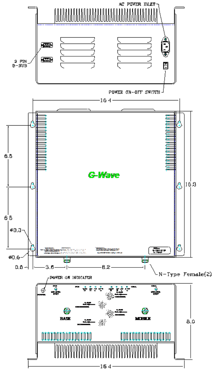
Mechanical Outline (Figure 2):
Page | 10
INSTALLATION:
DO NOT APPLY A.C. POWER TO THE RHBDA UNTIL CABLES ARE
CONNECTED TO BOTH PORTS OF THE RHBDA AND THE
ANTENNAS.
1. Set the BDA Rack on the floor or mount on a wall (where applicable). Using
appropriate screws and anchors, attach the BDA to the wall at the four mounting holes
on the side flanges. (Special version not shown in this manual).
2.
Ensure that the isolation between the donor antenna and the service antenna is at
least 12 dB greater than the BDA gain. (Use the higher of the Uplink and Downlink
gains reported on the BDA test data sheet).
3. Connect the cable from the donor antenna to the BDA connector labeled “BASE”
and the cable from the service antennas to the BDA connector labeled “MOBILE”.
4. See main Panel of the BDA and verify that both of the Uplink and Downlink
attenuation is set to 30 dB via dial Attenuator.
5. Connect the AC power cord to the BDA and then to the power source. Verify that
the “Power ON” lamp is illuminated.
Installation of the BDA is now complete. To adjust the gain controls to suit the specific
signal environment, refer to the next section of the manual.
Note:
For repeat installations of existing equipment, make sure the attenuation
is positioned to its maximum setting (30 dB). After verification attenuation,
follow the above steps starting with step 1.
Page | 11
OPERATION:
Refer to Figure 3 & 4 for adjustment access location, connectors and labels.
Variable Step Attenuator
BDA gain can be reduced by up to 30 dB in 2 dB steps using the variable step
attenuator. Gain adjustment is made with rotary switches located on the front panel of
the BDA enclosure. Arrows on the shafts of these switches point to the value of
attenuation selected. BDA gain can be determined by subtracting the attenuation
value from the gain reported on the BDA Test Data Sheet for that side of the unit. The
attenuators are labeled for Uplink and Downlink of each band (CELL and PCS).
ALC (Automatic Level Control)
To minimize intermodulation products, each amplifier in the BDA contains an ALC
feedback loop. The ALC circuit senses the output power and limits it to the factory
preset level of +33 dBm UL and +33 dBm DL.
ALC function is located in each power amplifier. A red LED indicator located on the
Front main panel (see figure 3) illuminates when output power meets or exceeds the
ALC preset point.
To establish proper operating gain on the Uplink and Downlink sides, start with the
Downlink. Observe the red LED indicator on the Downlink amplifier. Units are shipping
with maximum attenuation. Decrease attenuation one step at a time until the red LED
is lit. Then, using the Downlink step attenuator, increase the attenuation until the red
LED goes off. Repeat the process for the Uplink, and then repeat the process for the
second band. This setup should be done under RF signal transmit for either path the
level indicator is accurate to +/- 0.4 dB of the ALC set point.
Note: Operation of BDA-CELLAB/PCSF-33/33-80-AB at maximum gain
with greater than -40 dBm average power incidents on the MOBILE or BASE
ports could cause damage to the BDA.
Page | 12
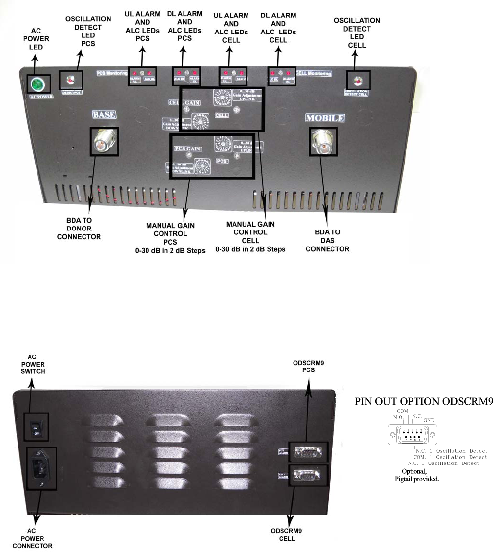
Variable Gain Adjustment and LED Indicators
Figure 3
Figure 4
Back Panel Connections
Page | 13
Page | 14
DIAGNOSTICS GUIDE
The BDA provides long term, care-free operation and requires no periodic
maintenance. There are no user-serviceable components inside the BDA.
This section covers possible problems that may be related to the installation or
operating environment.
Gain Reduction
Possible causes: Defective RF cables and RF connections to antennas, damaged
antenna or Leaky cable.
Excessive Intermodulation or Spurious
Possible causes: Amplifier oscillation caused by insufficient isolation. The isolation
between two antennae is given by the equation:
Isolation = 92.5 + 20 Log (F x D) – Gt – Gr
Where:
F = frequency (GHz)
D = separation (Km)
Gt = transmit antenna gain (in the direction of the receive antenna).
Gr = receive antenna gain (in the direction of the transmit antenna).
Occasional Drop-out of some Channels
Possible causes: One channel with very strong power dominates the RF output of the
amplifier.