G Way Solutions PS7PS82W80 DUAL BAND RF BI-DIRECTIONAL AMPLIFIER User Manual USERS MANUAL

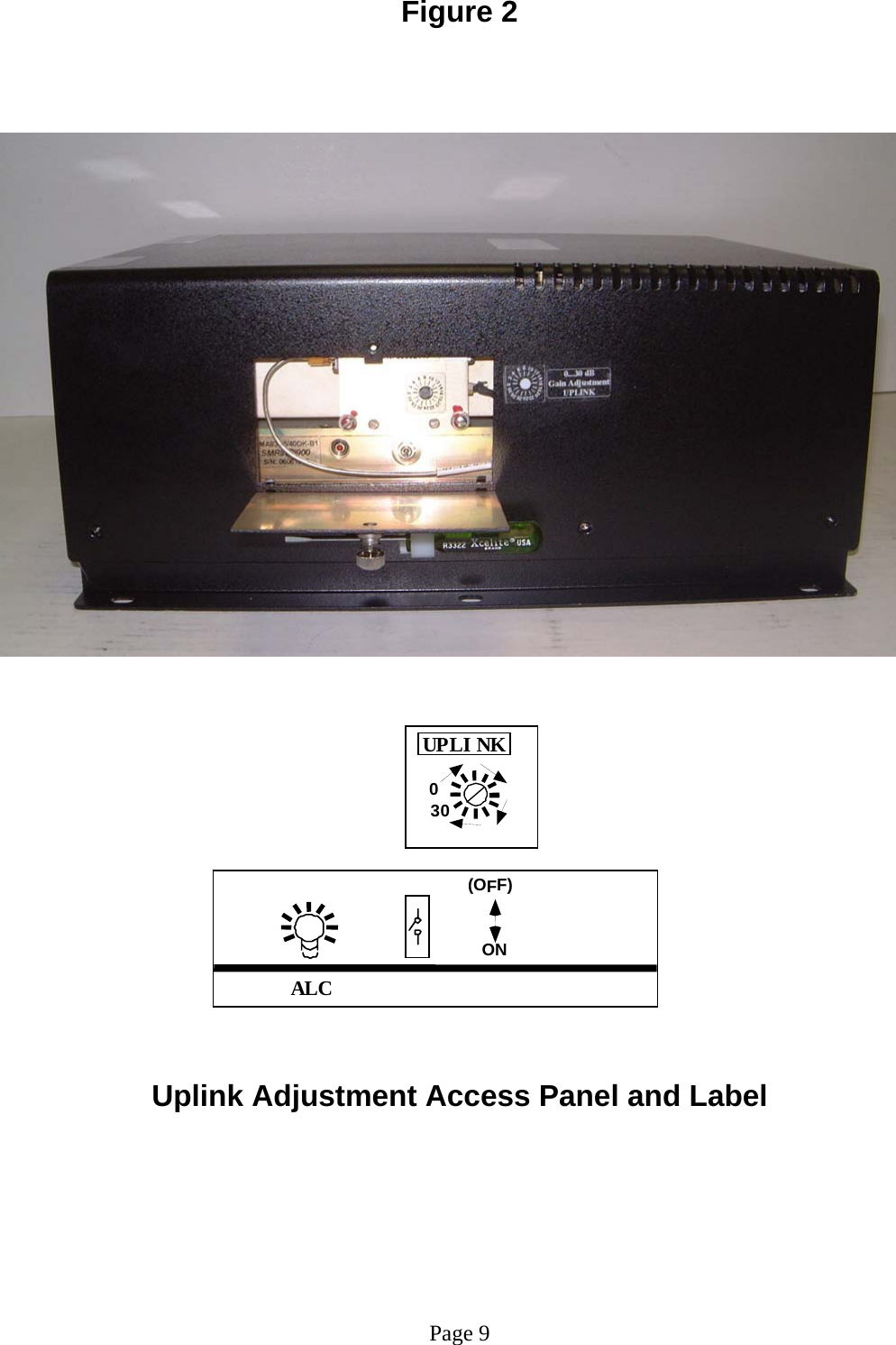
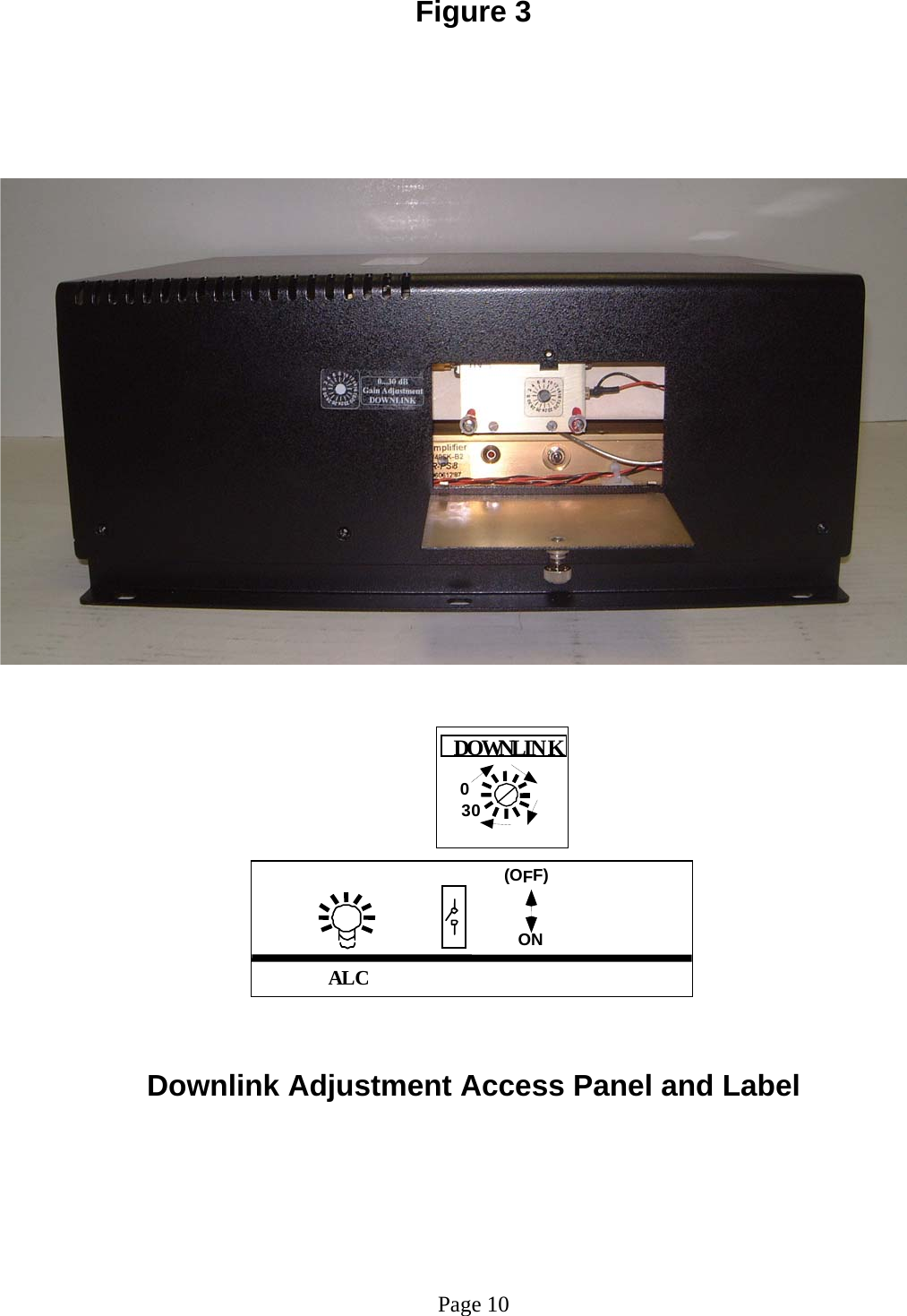
G-Way Microwave / G-Wave DUAL BAND RF BI-DIRECTIONAL AMPLIFIER USERS MANUAL

USERS MANUAL

     INSTALLATION AND OPERATING MANUAL  BDA-PS7/PS8-2/2W-80-A  DUAL BAND BI-DIRECTIONAL AMPLIFIER
TABLE OF CONTENTS   PARAGRAPH PAGE NO BDA OVERVIEW   3 BDA BLOCK DIAGRAM DESCRIPTION 3 ELECTRICAL SPECIFICATIONS   4 MECHANICAL SPECIFICATIONS   5  ENVIRONMENTAL CONDITIONS   5  BDA CONNECTIONS    5  MECHANICAL OUTLINE DRAWING (Figure 1 & 1a)  6  BDA INSTALLATION  7 BDA OPERATION 8  UPLINK MECHANICAL OUTLINE- ADJUSTMENT (Figure 2)  9  DOWNLINK MECHANICAL OUTLINE- ADJUSTMENT (Figure 3)  10 RF EXPOSURE WARNING   11 DIAGNOSTICS GUIDE  11                            Page 2
   BDA OVERVIEW:  The BDA assembly extends the coverage area of radio communications in buildings and RF shielded environments. The BDA has dual RF paths to extend coverage in two distinct frequency bands.     The unit features low noise figure and wide dynamic range. It is based on a duplexed path configuration with sharp out of band attenuation allowing improved isolation between the receiving and transmitting paths.     BDA DESCRIPTION:  The BDA Downlink path receives RF signals from the base station and amplifies and transmits them to the subscriber. The BDA Uplink path receives RF signals from the subscriber and amplifies and transmits them to the base station. The Uplink and Downlink occupy three distinct frequency bands. The frequency bands are as follows: 794-824 MHz for the Uplink and 764-776 MHz & 851-869 MHz for the Downlink. Two triplexers isolate the paths and route each signal to the proper amplifying channel.  An Automatic Level Control (ALC) allows for output power limiting. A variable step attenuator gives 0 – 30 dB of attenuation in 2 dB steps. The use of these controls is covered in the “OPERATION” section, later in this document.                        Page 3
ELECTRICAL SPECIFICATIONS:  Frequency Range         Downlink      : 764-776 and 851-869 MHz  Uplink       : 794-824 MHz  Pass band Gain @ min attenuation     : 80 dB minimum  Variable Step Attenuator Range      : 0-30 dB  (2-dB steps)  Pass band Ripple      : ±1.5 dB (typ)  Noise Figure @+25°C at max gain     : 5.5 dB max  3rd Order Intercept point          Uplink                                     : +46 dBm (typ)     Downlink                                      : +46 dBm (typ)   *Output Power @ 1dB Compression    Uplink       : +33 dBm (typ) Downlink      : +33 dBm (typ)  *ALC Factory Set Point  Uplink       : +26 dBm  Downlink      : +26 dBm   Isolation between Up/Down Link       : 100 dB min  Input/ Output Impedance    : 50 Ohms  VSWR (Input/Output)        : 1.5: 1 max  Pass band Gain @ min attenuation     : 80 dB minimum  Power Supply      : 110VAC/1.42Amp  : 240VAC/0.71 Amp : 50 to 60 Hz    *The Manufacturer's rated output power of this equipment is for single carrier operation. For situations when multiple carrier signals are present, the rating would have to be reduced by 3.5 dB, especially where the output signal is re-radiated and can cause interference to adjacent band users. This power reduction is to be by means of input power or gain reduction and not by an attenuator at the output of the device.     Page 4
 MECHANICAL SPECIFICATIONS:  Size        : 13.5 x 12.5 x 5.6 inch : (343 x 317.5 x 142.3 mm)  RF Connectors      : N-type Female  Weight       : 20.9 Lbs. (9.5kg.) approx.  ENVIRONMENTAL CONDITIONS:  The unit is designed for indoor applications:  Operating temperature: - 20°C to + 50°C  Storage temperature: - 50°C to + 90°C  BDA CONNECTIONS  The BDA AC power is accepted through a standard 3-wire male plug (IEC-320) with phase, neutral and ground leads. The AC power is wired to a high efficiency DC switching power supply which is CE and UL approved. The power supply runs the amplifiers and the Power On lamp. The metal enclosure of the BDA is connected to ground.   A 9-pin D-Sub connector provides failure alarm output contacts (see diagram next page) as well as an optional 12 VDC (250mA) auxiliary output.     The RF connections are made via two type “N” female connectors. The RF connector labeled “BASE” must be connected to the antenna pointing towards the base station. The RF connection labeled “MOBILE” must be connected to the antenna facing the area to be covered by the BDA.  The RF connections must be made through cables with characteristic impedance of 50 ohms.  The isolation between the base station antenna and the mobile antenna should be at least 12 dB higher than the BDA gain. Isolation less than this value can cause gain ripple across the band. Isolation equal to or less than the BDA gain will give rise to oscillations which will saturate the amplifiers and possibly cause damage to the BDA.          Page 5
             N.O.                                                          COM.                         N.C. IN BUILDING REPEATERFigure 1           BDA Mechanical Outline   Figure 1a    (Relay Shown in         Non-Alarm Condition) The alarm monitors current of both uplink and downlink amplifiers. An alarm condition                                                             will occur if either uplink or downlink amplifiers                                               are over or under its current tolerance.                                                                                             Page 6 Conditions for Optional Alarm
BDA INSTALLATION  DO NOT APPLY A.C. POWER TO THE BDA UNTIL CABLES ARE CONNECTED TO BOTH PORTS OF THE BDA AND THE ANTENNAS.    1. Mount the BDA on the wall with the RF connectors pointing DOWN. Using appropriate screws and anchors, attach the BDA to the wall at the four mounting holes on the side flanges.   2. Ensure that the isolation between the donor antenna and the service antenna is at least 12 dB greater than the BDA gain. (Use the higher of the Uplink and Downlink gains reported on the BDA test data sheet).   3. Connect the cable from the donor antenna to the BDA connector labeled “BASE” and the cable from the service antennas to the BDA connector labeled “MOBILE”.   4. Open the adjustment access panels on the sides of the BDA and verify that both of the attenuator’s are positioned to its maximum setting (30 dB). Close the panels.   5.  Connect the AC power cord to the BDA and then to the power source. Verify that the “Power ON” lamp is illuminated.    Installation of the BDA is now complete. To adjust the gain controls to suit the specific signal environment, refer to the next section of the manual.  Note: For repeat installations of existing equipment, make sure the attenuation is positioned to its maximum setting (30 dB). After verification of the attenuation, follow the above steps starting with step 1.                 Page 7
BDA OPERATION  Refer to Figure 2 & 3 for adjustment access location and label.   Variable Step Attenuator BDA gain can be reduced by up to 30 dB in 2 dB steps using the variable step attenuator. Gain adjustment is made with rotary switches accessible via the access door on the BDA enclosure. Arrows on the shafts of these switches point to the value of attenuation selected. BDA gain can be determined by subtracting the attenuation value from the gain reported on the BDA Test Data Sheet for that side of the unit.  The attenuators are labeled for Uplink and Downlink.   ALC (Automatic Level Control)  To minimize intermodulation products, each amplifier in the BDA contains an ALC feedback loop. The ALC circuit senses the output power and limits it to the factory preset level of +26 dBm.   ALC function is located on each amplifier and accessible via the access door on the BDA enclosure. A red indicator lamp located on each amplifier illuminates when output power meets or exceeds the ALC set point. The indicator is functional regardless of the position of the ALC momentary switch.  To establish proper operating gain on the Uplink and Downlink sides, start with the Downlink. Observe the red indicator lamp on the Downlink amplifier. Units are shipping with maximum attenuation. Decrease attenuation one step at a time until the lamp is lit. Then, using the Downlink step attenuator, increase the attenuation until the lamp goes off. Repeat the process for the Uplink. The level indicator is accurate to +/- 0.4 dB of the ALC set point.    Operation of BDA-PS7/PS8-2/2W-80-A at maximum gain with greater than -43 dBm average power incident on the MOBILE or BASE ports can cause damage to the BDA.                 Page 8
Figure 2                                                          Uplink Adjustment Access Panel and Label         Page 9  (OFF)ONA L C030UPLI NK
Figure 3                                                          Downlink Adjustment Access Panel and Label       Page 10 030DOWNLINK (OFF)ONALC
RF EXPOSURE WARNING  The antenna used for this transmitter must be fixed-mounted on outdoor permanent structures. In order to satisfy the FCC RF exposure requirements, the BDA/antenna installation must comply with the following:  The downlink indoor antenna (Omni type or similar directional antenna) must be installed so as to provide a minimum separation distance of 0.35 meters (35 cm) between the antenna and persons within the area. (This assumes a typical antenna with maximum gain of [2 dBi, VSWR >?> 1.5:1, Zo= 50 ohms, and a cable attenuation of between 2-10 dB)  The uplink outdoor antenna (Yagi type or similar directional antenna) must be installed so as to provide a minimum separation distance of 0.35 meters (35 cm) between the antenna and persons within the area. (This assumes a typical antenna with maximum gain of [13 dBi, VSWR >?> 1.5:1, Zo= 50 ohms, and a cable attenuation of between 2-10 dB).  DIAGNOSTICS GUIDE  The BDA provides long term, care-free operation and requires no periodic maintenance. There are no user-serviceable components inside the BDA. This section covers possible problems that may be related to the installation or operating environment.  a. Gain Reduction Possible causes: Bad RF cables and RF connections to antennas, damaged antennas.  b. Excessive Intermodulation or Spurious Possible causes: Amplifier oscillation caused by insufficient isolation. The isolation between two antennas is given by the equation: Isolation = 92.5 + 20 Log (F x D) – Gt – Gr Where: F = frequency (GHz)       Gt = transmit antenna gain (in the direction of the receive antenna) D = separation (Km)       Gr = receive antenna gain (in the direction of the transmit antenna)  For example, at the SMR frequencies, the antenna isolation at 100 m separation is about 71 dB for omni-directional antennas (0 dB gain). To increase isolation, the antennas should have higher directivity and must be pointed away from each other.  c. Occasional Drop-out of some Channels Possible causes: One channel with very strong power dominates the RF output of the amplifier.     38 Leuning Street South Hackensack, NJ 07606 Tel. 201-343-3140   Fax 201-343-6390 sales@gwaverf.com www.gwaverf.com   Page 11

Navigation menu