G Way Solutions VHF2W80 VHF Booster User Manual BDA VHF 33 33 80 20U18 revA
G-Way Microwave / G-Wave VHF Booster BDA VHF 33 33 80 20U18 revA
UserManual.wiki
>
G Way Solutions
>
VHF2W80 User Manual
Users Manual
Navigation menu
Upload a User Manual
Namespaces
Wiki Guide
HTML
PDF
Info
Views
User Manual
Discussion / Help
Navigation
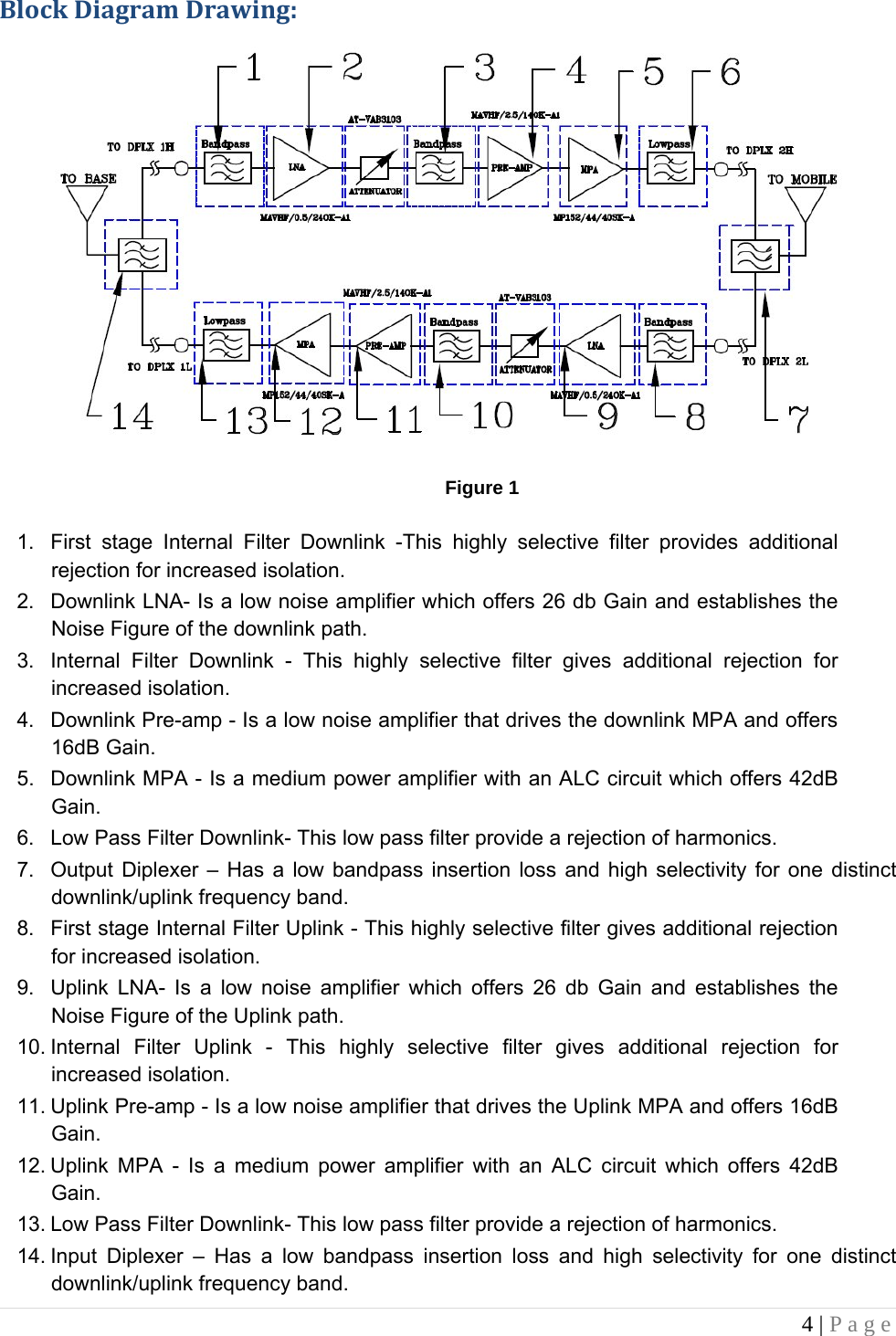
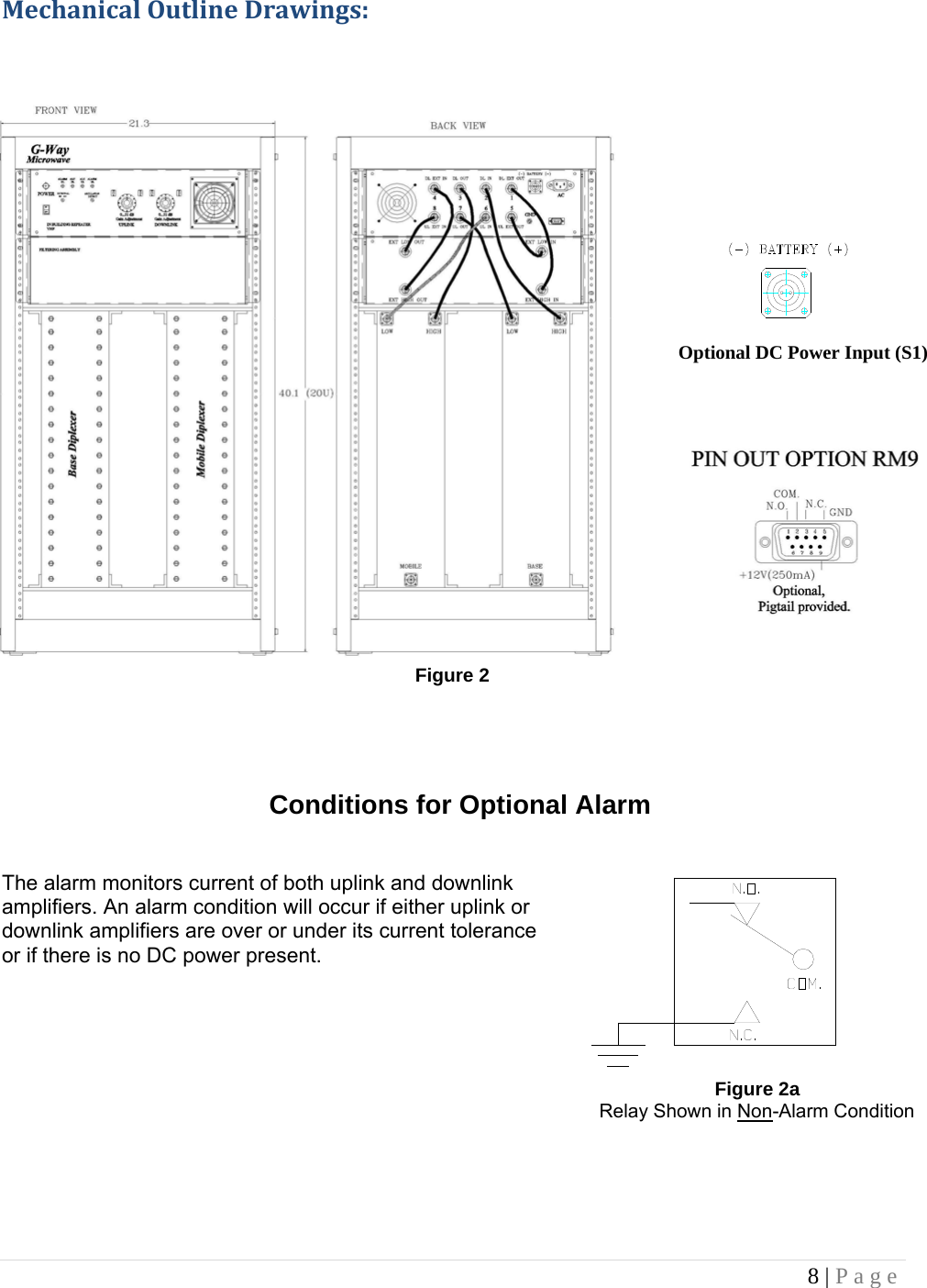
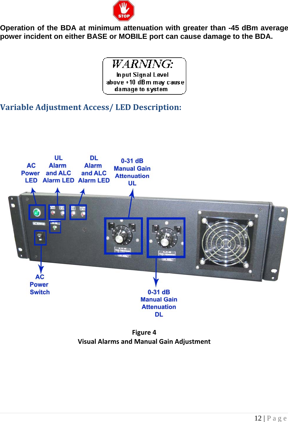
![3 | Page BDAOVERVIEW: The BDA assembly extends the coverage area of radio communications in buildings and RF shielded environments. The unit features low noise figure and wide dynamic range. It is based on a duplexed path configuration with sharp out of band attenuation allowing improved isolation between the receiving and transmitting paths. Due to significant size of the diplexers and/or High “Q” filters needed to achieve specified gain, the system is built as Amplifier 19” Drawer and external filters, assembled into a 19”, 20U cabinet. VHFPartNumberDescription:BDA-V(XXX)/(YYY) – 33/ 33-80-(ZZZ) V(XXX)(YYY)333380(ZZZ)BDA High Band Center Frequency [MHZ] Low Band Center Frequency [MHZ] UL Composite Power [dbm] DL Composite Power [dbm]Gain Enclosure Table 1 BDABlockDiagramDescription: Refer to Figure 1, on page 4 for the following discussion. The BDA Downlink path receives RF signals from the base station and amplifies and transmits them to the subscriber. The BDA Uplink path receives RF signals from the subscriber and amplifies and transmits them to the base station. The Uplink and Downlink occupy two distinct frequency bands. For example, a sample frequency band in VHF is as follows: 158-159 MHz for the Uplink and 154-156 MHz for the Downlink. Two diplexers isolate the paths and route each signal to the proper amplifying channel. An Automatic Level Control (ALC) allows for output power limiting. A variable step attenuator gives 0 – 31 dB of attenuation in 1 dB steps. The use of these controls is covered in the “OPERATION” section, page 10. OptionalEquipmentOverview:a) Visual Alarms All G-Wave BDAs feature visual alarms as a standard. LEDs are provided for UL and DL alarms, ALC UL and DL alarms as well as Power indicator. b) DC Input Power Option (S1) The BDA is equipped with both AC and DC voltage inputs for power operation. This gives the flexibility of powering the BDA with either an AC or DC source. If both sources are connected, the BDA will automatically select the stronger source for power. c) Remote Monitoring via 9-Pin Dry Contact Connector (RM9) A 9-Pin dry contact will be provided to hard wire into a building’s alarm system. Dry contact will provide alarms for ALC and amplifier failure.](https://usermanual.wiki/G-Way-Solutions/VHF2W80/User-Guide-2440126-Page-3.png)