G4S Technology S884B S884B Proximity Reader User Manual manual
G4S Technology Limited S884B Proximity Reader manual
manual
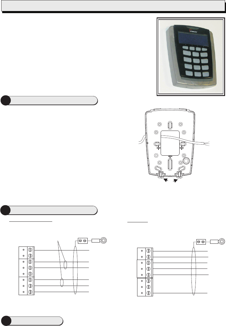
Mount the backplate using countersunk headed screws
adjacent to the opening edge of the door and at a
convenient height (recommended height is 5' (1.5m) to top
of unit).
If fixing hole ’A’ is used then the breakout must be removed
and the screw must not protrude.
Feed the required cables through the backplate:
·The cable from the controller.
·A cable from a External Reader (Optional).
·General Purpose Input / Output cable (Optional)
If wall tamper function is to be used then breakout ‘B’ must
be removed and an appropriate wall screw fitted through
the hole to actuate the tamper lever.
2
1Mount the Backplate
Reader Connections
The S884 is a
and keypad. The reader can be set to use Wiegand or
The S884 reader will read smartMAX encoded MIFARE cards
and card serial numbers from most ISO 14443A smart cards
which have a 4-byte UID (User Identification). The reader may
be configured to read other card types by presenting a
programming card to the reader during start up.
contactless smart-card reader, with Graphic LCD
20mA
current loop communications.
The securing screws ‘C’ are integral to the backplate and are unscrewed via the small holes in the
enclosure so that the screw heads locate in the counterbored holes on the inside of the
enclosure.
You should find that
the backplate has
holes for connection
to most standard
electrical backboxes.
C
AB
Installation and User Instructions for S884 Readers
0V
RX+
RX-
TX+
TX-
12V
Controller
0V
TX+
TX-
RX+
RX-
+V
Reader
TB1
20mA current loop
0V
Green
Data 0
Red
Data 1
12V
Controller
0V
GRN
0
+V
Use Belden
9537 Cable
Wiegand
RED
1
Reader
TB1
Connect shield at
controller end
only.
Connect shield
at controller end
only.
Twisted pairs (use
Belden 9503 Cables)
Note: Use LK2 to select the communications mode (See Step 3).
Set LK2 (COMMS) across the center and W pin for Wiegand communications, or across the center and C
pin for 20mA current loop communications. Set LK3 (USER Keypad audio feedback) to 1 for sound on, or
0 for sound off. Set LK4 (EXT RDR) across the center and W pin for Wiegand communications, or across
the center and M pin for Magstripe Reader communications.
3Reader Links
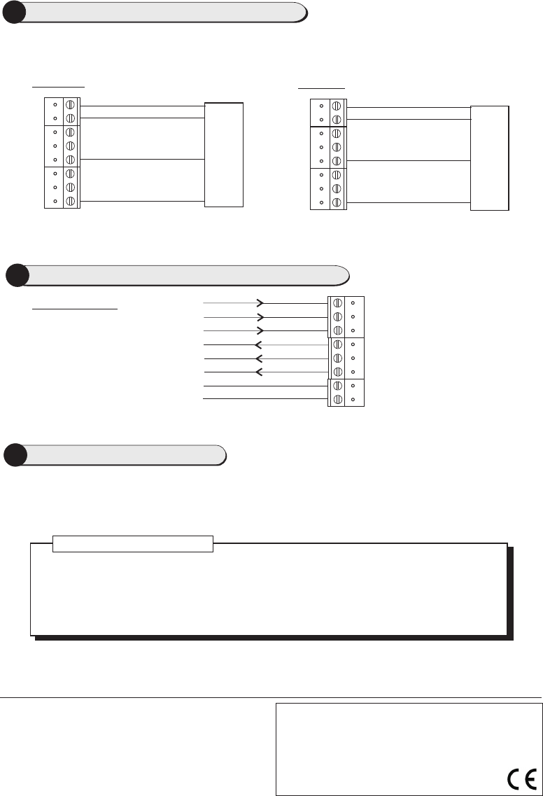
4External Reader Connections (Optional)
0V
0/CK
1/DA
+V
Reader
TB1
Magstripe
0V
0/CK
1/DA
+V
Reader
TB1
Wiegand
Wiegand Reader
Magstripe Reader
IN 1
IN 2
C
SPKR
Reader
TB2
I/O Connections
5General Purpose Inputs & Outputs (Optional)
COM
NC
NO
SPKR
Present the card face-on to the reader until you hear a "bleep". Cards can be presented in rapid succession;
there is no need, for example, to wait for "UNLOCKED" to disappear before presenting another.
If the reader has been enabled for user-code mode at the controller, you can gain access by pressing the O
key, entering your card number, then pressing the P key.
A Setup menu can be displayed by pressing the O and P keys simultaneously while power is applied. You
can use the menu to change the contrast and language used for the LCD (default English). Use the four
function keys to navigate around the menu.
9600-0537. Installation and User Instructions for S884 Readers,
Issue 1.0 11th March 2010. G4S Technology, 2010.
FCC Notice: This device complies with Part 15 of the FCC Rules.
Operation is subject to the following two conditions: (1) This device
may not cause harmful interference, and (2) this device must accept
any interference received, including interference that may cause
undesired operation.
Any unauthorized modification to this device may void the authority of
the user to operate it. All trademarks acknowledged.
©
LED Status Indicator
GREEN – The lock is released and you may open the door.
RED – You do not have access rights to gain entry, or the reader did not read your card
properly (in this case, present it again).
YELLOW – Enter your PIN. If you make a mistake, the message INVALID PIN is momentarily
displayed, followed by ENTER PIN, to prompt you to try again.
Specifications
Input voltage: 9-14Vdc.
Input current: 200mA @ nom. 12Vdc.
Operating temperature: 14 to 131°F (-10 to 55°C)
Operating humidity: 15 to 90%, non-condensing.
Maximum read range: 4" (100mm).
Approvals: EN50133, EN302291, EN301489
6Using the Reader
Note: Use LK4 to select the External Reader type (See Step 3).
The reader is connected to the controller using the 20mA current loop scheme shown in section 2 and, in
addition, the external reader is connected as shown below.
0V
Clock
Data
12V
0V
0s
1s
12V