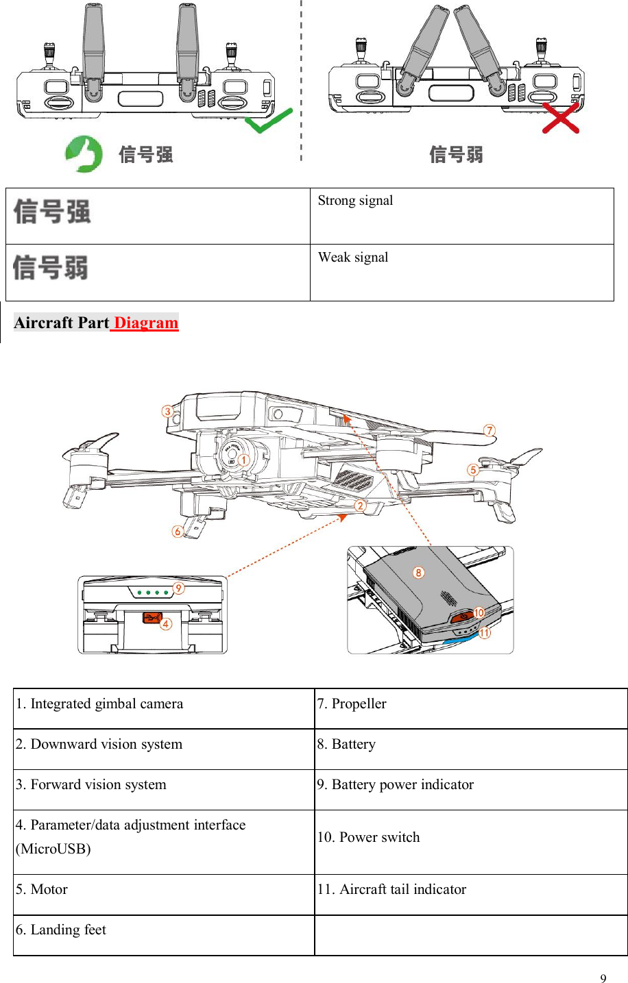
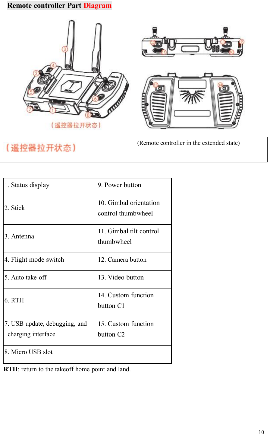
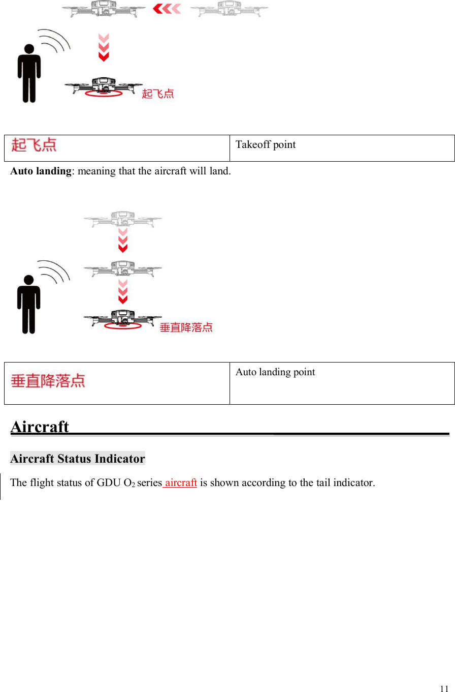
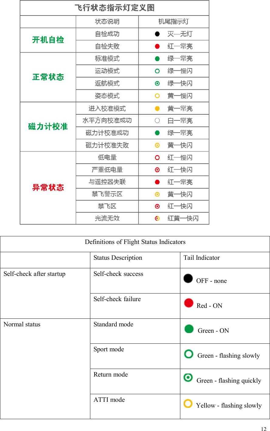
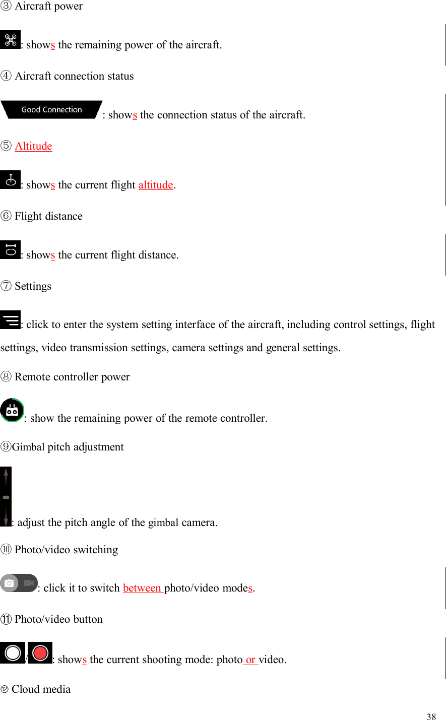
GDU Tech PD-O2-PLUS GDU O2 PLUS User Manual
Prodrone Technology (Shenzhen) Co., Ltd GDU O2 PLUS
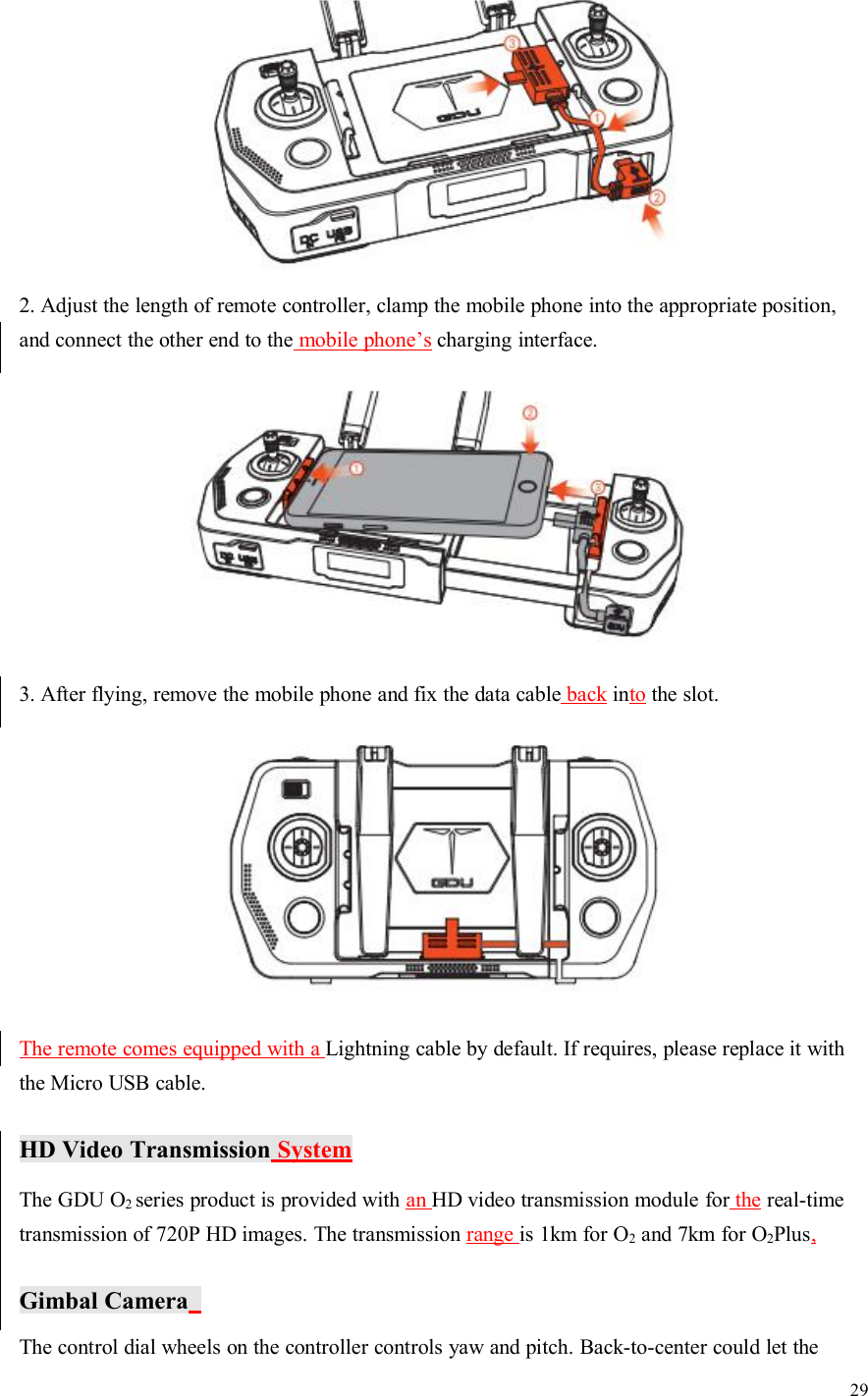
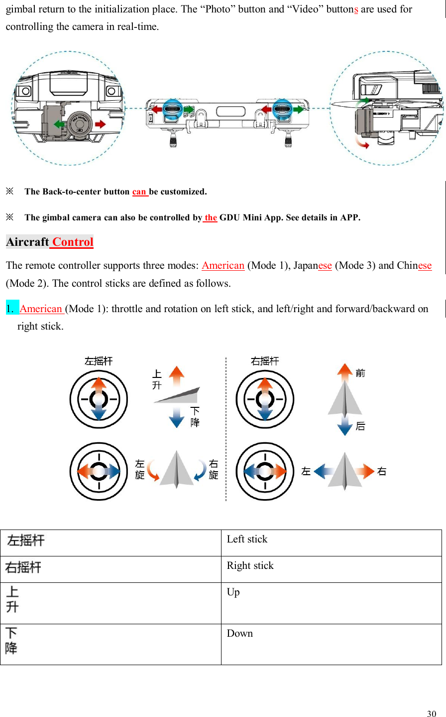
UserManual.wiki
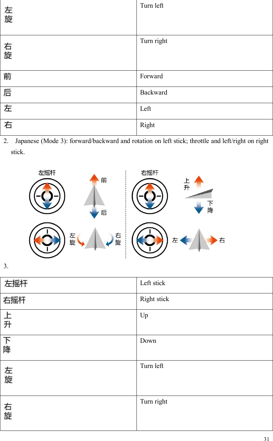
>
GDU Tech
>
PD O2 PLUS User Manual
User Manual
Navigation menu
Upload a User Manual
Namespaces
Wiki Guide
HTML
PDF
Info
Views
User Manual
Discussion / Help
Navigation