GDU Tech PD-RC03-PLUS GDU Remote controller User Manual
Prodrone Technology (Shenzhen) Co., Ltd GDU Remote controller
GDU Tech >
user manual
User Manual V1.0
Contents
Features.............................................................................................................................................. 3
Slide Arm technology....................................................................................................................3

2
Stabilized Video and Photo Camera System...............................................................................4
HD Video Transmission................................................................................................................4
Vision position System................................................................................................................. 5
User Instructions................................................................................................................................5
Warning.......................................................................................................................................... 5
Get To Know O2............................................................................................................................ 5
GDU Mini App Download........................................................................................................... 6
Product Registration......................................................................................................................6
UAV Legal Registration............................................................................................................... 6
Safety Overview................................................................................................................................. 6
Product Overview............................................................................................................................ 7
Aircraft and Remote controller Preparation................................................................................7
Aircraft Part Diagram....................................................................................................................9
Remote controller Part Diagram................................................................................................ 10
Aircraft..............................................................................................................................................11
Aircraft Status Indicator..............................................................................................................11
Flight Mode..................................................................................................................................13
Automatic Return Home.............................................................................................................14
Vision Position System...............................................................................................................15
Smart Flight Function................................................................................................................. 17
Propellers......................................................................................................................................22
Battery.......................................................................................................................................... 24
Remote controller............................................................................................................................27
Prepare the Remote controller....................................................................................................27
Mobile Phone Installation...........................................................................................................28
HD Video Transmission System................................................................................................29
Gimbal Camera............................................................................................................................29
Aircraft Control........................................................................................................................... 30
Frequency Matching....................................................................................................................33
Flight Mode Selection.................................................................................................................33

3
Upgrading the Remote controller...............................................................................................34
Gimbal Camera................................................................................................................................ 34
Camera Overview........................................................................................................................34
Gimbal Overview........................................................................................................................ 35
GDU Mini App.................................................................................................................................. 35
Drone............................................................................................................................................ 36
Media............................................................................................................................................42
Explore......................................................................................................................................... 44
Me................................................................................................................................................. 46
Flight................................................................................................................................................. 46
Preflight Check............................................................................................................................46
Magnetometer Calibration..........................................................................................................47
General Flight Operations...........................................................................................................50
Technical Parameters......................................................................................................................52
Certification Information................................................................................................................ 54
Features
Slide Arm technology
The aircraft’s slided armsand folding landing pad and blade are designed to form a functional and
4
portable structure without sacrificing strength or flexibility.
Stabilized Video and Photo Camera System
Using new integrated control algorithmsand ahigh-precision three-axis stabilization design, 4K
ultra-high-definition videosand 13,000,000-pixel photos can be taken on a stable platform,
offering excellent photographic effects and recording experiences.
HD Video Transmission
The aircraft is equipped with aHD transmission module for real-time transmission of HD videos
and photography. The transmission range is 1km for O2products and 7km for O2Plus products
Smart Lock Prop
In order to fully protect your safety, the propeller of the GDU O2series enjoys dual protection.
Designed with 2 small set screws and a second proprietary locking mechanism, the props on the
O2 will ensure they stay secured during flight.
5
Vision position System
Our advanced forward and downward is onboard the GDU 02 series, thus achieving intelligent
obstacle avoidance, follow me, vision circle, and gesture shot. With the powerful vision system,
the aircraft is made more intelligent.
User Instructions
Warning
Thank you for using this GDU product. Improper operation of any special electronic productsmay
result in damages, personal injury,and even death, and the user should bear the legal
consequences of these actions. The product must not be used by juveniles under the age of 18. In
order to ensure a positive operating experience and to protect your personal safety, please
carefully read the following documents before use.
“Disclaimer”
“List of Items”
“User Manual”
“Quick OperationsGuide”
“Battery Safety Guide”
“Daily Maintenance Manual”
※The parameters in the documents only represent the delivery status. The actual parameters will prevail.
Get To Know O2
In addition to this document, GDU also provides a basic instructional video.
You can log in to the official website at http://www.gdu-tech.com/cn/ or by scanning the QR code
below to access and view the teaching video, which will give you an intuitive understanding of
how to use the product. It is recommended to watch the teaching video in aWIFI-supported
6
environment.
GDU Mini App Download
For an optimal operating experience, please download the GDU Mini App by logging on the
official website www.gdu-tech.com or by scanning the QR code below, and then install the GDU
Mini App.
※Please either use the iOS8.0 or the Android5.0 OS or above to install the GDU Mini APP.
Product Registration
To ensure complete after-sales services, please log on to the official website www.gdu-tech.com
and register your product. Registration will not affect your normal use of the product, but it is
recommended to promptly complete registration to become a GDU member. You can obtain the
latest official event information and occasional promotional information as recommended by
GDU.
UAV Legal Registration
As per the Provisions on Real-time Registration Management of Civil Unmanned Aerial Vehicles
of the Civil Aviation Administration of China, all UAV ownersmust register their real name and
fill any related information at time of purchasing their UAV in the official government UAV
registration system (http://uas.caac.gov.cn), and paste the registration mark on the hull of the
UAV.
※The personal information of the user will be kept strictly confidential after registration.
Safety Overview
1. Environmental Requirements
• Do not use the aircraft under severe weather conditions such as rain, lightning, heavy winds,
heavy fog, dust,and extreme cold.

7
• Signals will be blocked by buildings, trees, and other environmental obstructions resulting in
possible GPS positioning failure or control disconnection. Please only use the product in open
spaces.
• Please use the product only within your own visual range, and avoid any obstacles, people, water,
etc.
• Do not use the product in proximity to high-voltage communications towers,in order to prevent
interference with remote controller signals.
• Be careful when using the product at altitudesof 4000m, or as performance is greatly reduced
and aircraft could be dangerous to operate.
• Please only use the product in legally permitted areas.
2. Operating Instructions
• Do not call or answer the phone while product is in flight. Pay close attention to the GDU
Mini App interface to ensure a safe flight.
•After receiving a low power alert signal, please return and land as soon as possible.
• The aircraft will be forced to return upon receiving an emergency low power alert.Please
control the aircraft to allow it to land into a safe place.
• After landing, first turn off the aircraft’s power supply, then conduct any other operations.
• Do not stop the motor in mid-flight except in case of emergency, in order to prevent any
injuries caused by the falling aircraft.
• The propellers are dangerous when rotating at high speed. Please keep a safe distance from
the aircraft in order to ensure your safety.
3. Maintenance
•Please replace the battery promptly in the case the battery exhibits damage, bulging,or leakage.
•If the motors produce abnormal sounds, this may be caused by bearing wear. Please replace
the motor by contacting Customer Support.
•Promptly replace any deformed or damaged propeller blades.
•Keep the gimnal camera lens clean. Only use the special cleaning kit to wipe it.
Product Overview
Aircraft and Remote controller Preparation
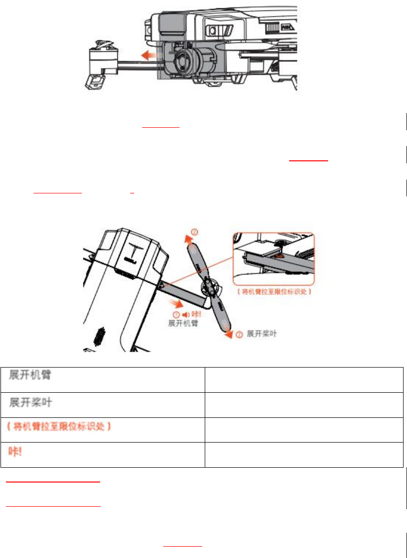
1. Remove the cover from the aircraft.
8
※The cover is used for protecting the equipped gimbal camera. Confirm that the holder cover has been
removed before using the aircraft.
※It is recommended to install the holder cover to protect the gimbal camera whenever the aircraft is not
in use.
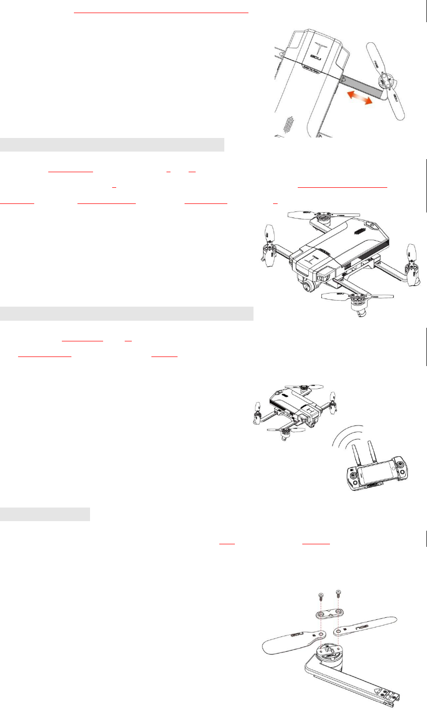
2. Pull out each of the aircraft armsto the limit mark, and fully unfold the propellers and landing
feet to completely.
Extend the propeller
Extend the blade
(Pull the arm to the limit mark)
Click!
※While extending the arm, Be sure to pull firmly and carefully and do not extend past limit marks.
※While retracting the arm, Firmly push the arm back to the proper position, while being sure to guide
props into their grooves, until the clicking sound is heard.
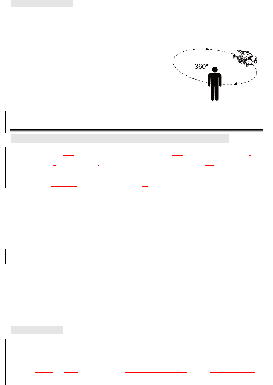
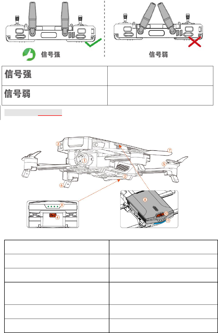
3. Correctly position the remote controller antennae.
9
Strong signal
Weak signal
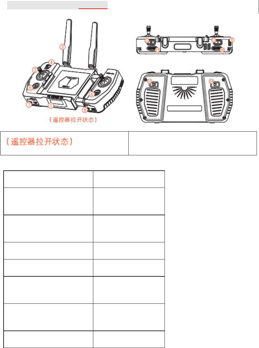
Aircraft Part Diagram
1. Integrated gimbal camera
7. Propeller
2. Downward vision system
8. Battery
3. Forward vision system
9. Battery power indicator
4. Parameter/data adjustment interface
(MicroUSB)
10. Power switch
5. Motor
11. Aircraft tail indicator
6. Landing feet
10
Remote controller Part Diagram
(Remote controller in the extended state)
1. Status display
9. Power button
2. Stick
10. Gimbal orientation
control thumbwheel
3. Antenna
11. Gimbal tilt control
thumbwheel
4. Flight mode switch
12. Camera button
5. Auto take-off
13. Video button
6. RTH
14. Custom function
button C1
7. USB update, debugging, and
charging interface
15. Custom function
button C2
8. Micro USB slot
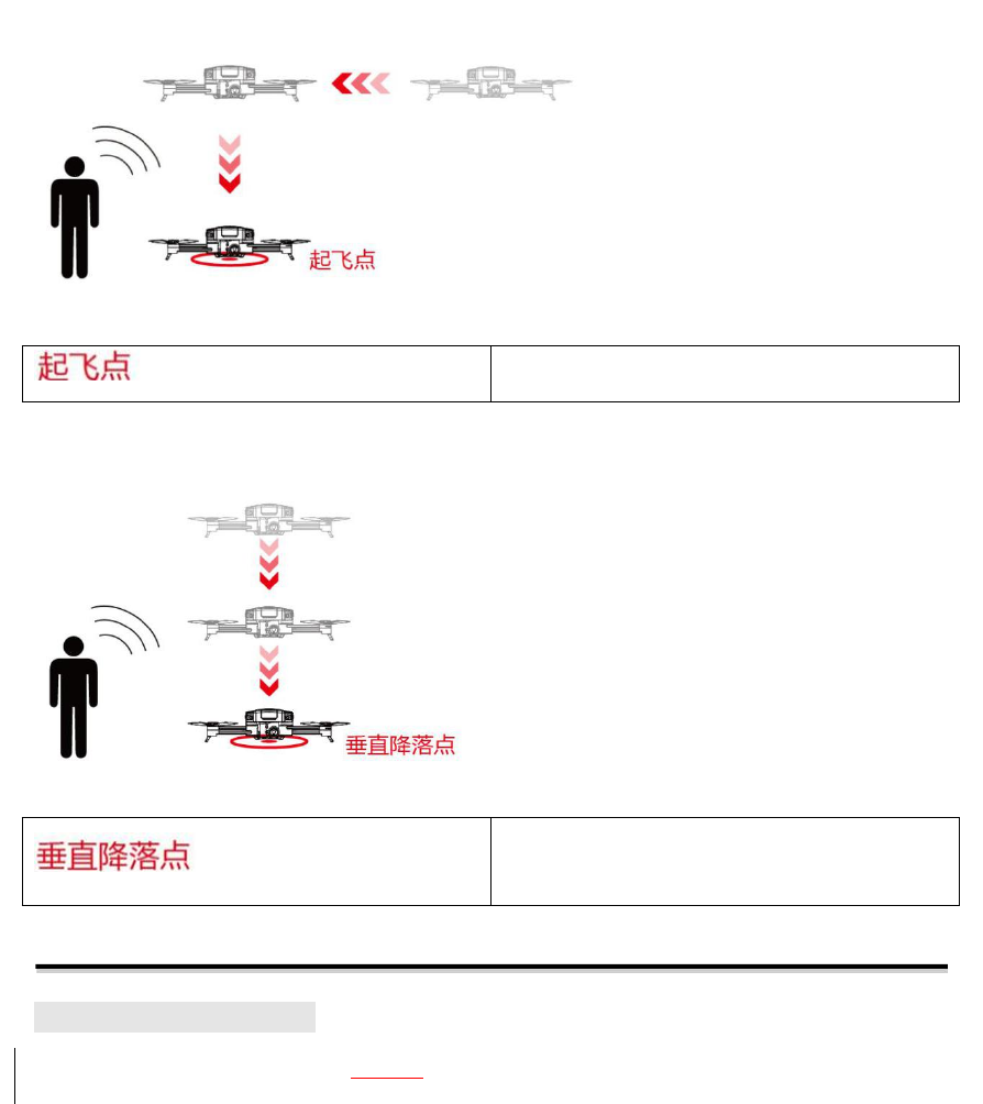
RTH: return to the takeoff home point and land.
11
Takeoff point
Auto landing: meaning that the aircraft will land.
Auto landing point
Aircraft
Aircraft Status Indicator
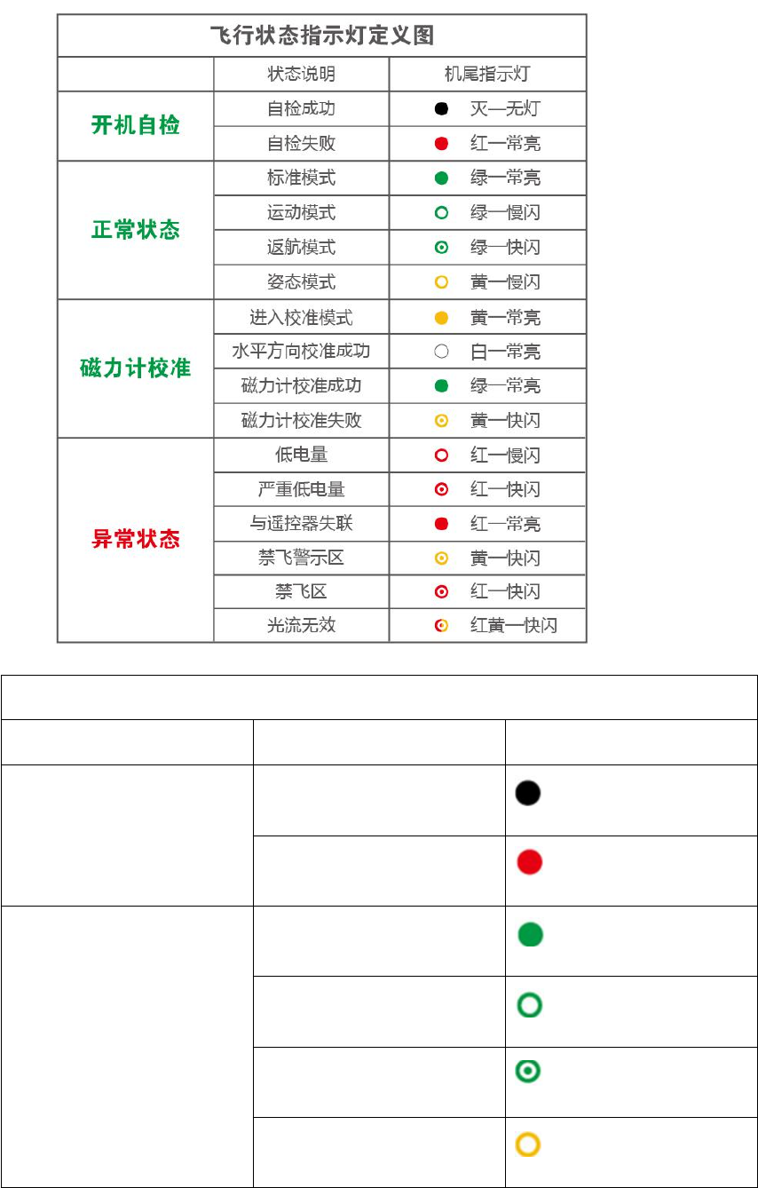
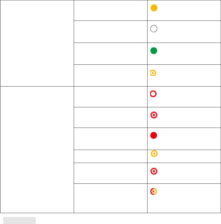
The flight status of GDU O2series aircraft is shown according to the tail indicator.
12
Definitions of Flight Status Indicators
Status Description
Tail Indicator
Self-check after startup
Self-check success
OFF - none
Self-check failure
Red - ON
Normal status
Standard mode
Green - ON
Sport mode
Green - flashing slowly
Return mode
Green - flashing quickly
ATTI mode
Yellow - flashing slowly
13
Magnetometer calibration
Calibration start
Yellow - ON
Calibration success in
horizontal direction
White - ON
Success of magnetometer
calibration
Green - ON
Failure of magnetometer
calibration
Yellow - flashing quickly
Abnormal status
Low power
Red - flashing slowly
Severe low power
Red - flashing quickly
Loss of connection with
remote controller
Red - ON
Close to NFZ (No Fly Zone)
Yellow - flashing quickly
NFZ (No Fly Zone)
Red - flashing quickly
Vision position ineffective
Red/yellow - flashing
quickly
Flight Mode
The GDU O2series product supports two flight modes:
1. Standard mode (maximum flight speed: 5m/s)
Accurate hovering and smart flight can be achieved through the use of the GPS module and vision
position system.
If the GPS signal is strong, the aircraft will be positioned through GPS;
If the GPS signal is too weak, and the light levels meet the needs of the vision position system,
then the aircraft will be positioned through the vision position system;
If the GPS signal is weak and the light condition do not meet the needs of the vision position
system, the aircraft will not hover accurately, and the GDU Mini App will prompt the user to land.
2. Sport mode (maximum flight speed: 15m/s)
The aircraft will hover accurately using the GPS module. The maximum flight speed can be
14
increased by adjusting the aircraft control sensitivity.
Attention! If the sport mode is selected during the flight process, the forward vision system will
automatically shut down, and the aircraft will cease actively braking and avoiding obstacles. The
user must pay attention to the surrounding environment and control the aircraft to avoid obstacles
along the flight route.
Attention! The flight speed and landing speed of the aircraft will be higher in sport mode than in
standard mode, so the braking distance will significantly increase. In a windless environment, the
user should reserve a braking distance of 30m at least to ensure flight safety.
Attention! The control sensitivity of the aircraft will be significantly improved in sport mode. The
aircraft will respond strongly and fly far in response to even minor operations of the remote
controller. In actual flight situations, the user should ensure sufficient flying space to ensure flight
safety.
Automatic Return Home
The GDU O2series product has the function of automatic return home in three modes, i.e.
“Automatic return home”, “Low power return” and “Communication loss return.”
If a return point has been recorded successfully before takeoff, the aircraft will automatically
return and land in the takeoff area once the user triggers automatic return home mode, low power
return mode, or communication (between the remote controller and aircraft) loss control mode.
The return point, also known as the HOME point, is defined as the valid GPS coordinates recorded
at the time of takeoff or when flight conditions enjoy strong GPS signals. A return point is valid
only for the current flight.
If automatic return is triggered, the aircraft will return at the current height if the distance between
the aircraft and return point is less than 20m. Otherwise, the aircraft will rise to the preset height
(if the current height is above the set height, the aircraft will fly at the current height), fly to
directly above the return point, and then slowly land.
※Please set the return height in the flight setting interface of the GDU Mini App.
1. Automatic return home
Automatic return can be triggered during the flight process by pressing the “Return” button on the
remote controller or by clicking “ ” in the GDU Mini App interface. During the return process,
the user can press the “Return” button or click “ ” in the GDU Mini App interface to exit the
return cycle and regain active control.
2. Low power return

15
Three mechanisms are provided:low power alarm, low power return,and emergency low power
landing.
Low power alert
If the remaining power is 30% or less of total power, the low power alert will be triggered, the red
indicator will flash slowly, and the GDU Mini App will remind the user of the low power levels.
Low power return
If the remaining power is 20% or less of total power, the aircraft will be forced to return
automatically. During the return process, the aircraft can be controlled by remote controller
(assuming standard signal levels).
Emergency low power landing
If the remaining power is 8% or less of total power, this will constitute a power emergency, and
the aircraft will be forced to land vertically.
※The throttle lever can be adjusted to position the aircraft into a more appropriate position before
landing.
※If the battery power is too low for the aircraft to return, the user should immediately land the aircraft.
3. Communication loss return
If the GPS signal is strong, and the compass is operating normally, then a return point will be
successfully recorded by the aircraft. If the remote controller’s signal is interrupted, the aircraft
will remain hovering. If the duration of signal interruption exceeds 3s, the aircraft will
automatically return. Under WIFI control, if the duration of APP signal interruption exceeds 30s,
the aircraft will then also return automatically. If normal signal conditions are recovered during
the return process, the aircraft will continue returning, but the user can press the “Return” button
on the remote controller or click “ ” on the GDU Mini App interface to exit the return
process.
※WIFI control is only applicable to GDU O2.
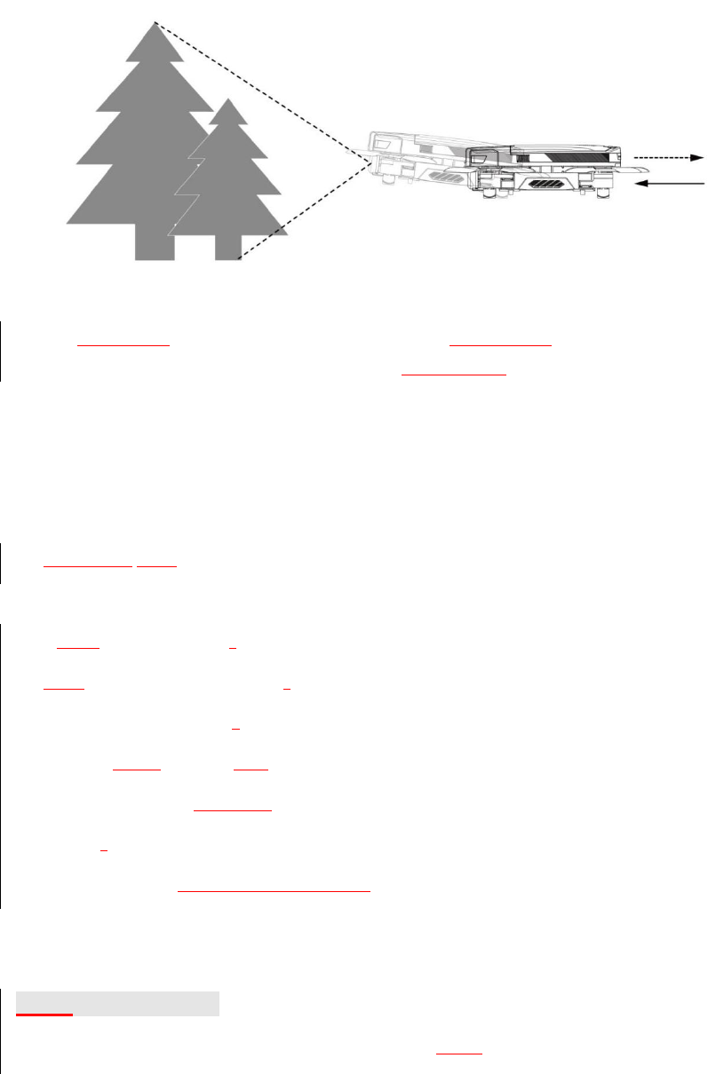
Vision Position System
The vision position system includes the forward vision system and the downward vision system.
The forward vision system on two sides of the nose includes two lenses, and used for sensing
obstacles by visual distance identification. The downward vision system at the bottom of the
aircraft includes optical and ultrasonic sensors, and used to obtain the location information of the
aircraft with optical sensor to provide the location reference along the horizontal axis. The current
flight height can be judged through ultrasonic sensor, thus providing a vertical height reference
and allowing flight at a fixed height.
16
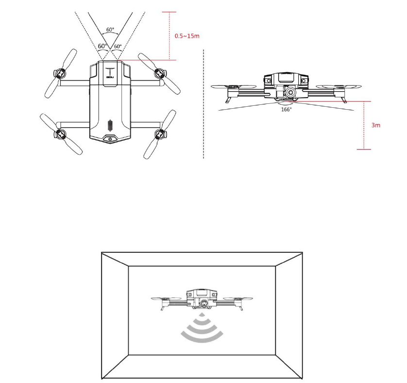
Observation Range
See the figure below for the observation ranges of the forward vision system and downward vision
system. If obstacles exist outside these ranges, the aircraft cannot effectively avoid them; please
fly carefully.
Downward Vision System Application Scenario
The downward vision system is effective with height less than 3m, in poor GPS signal conditions.
It is particularly applicable to indoor flight.
Operating Steps
1. Use the remote controller to switch the flight mode into standard mode.
2. Turn on the aircraft’s power supply. Wait until the flight status indicator is a steady green ON.
3. Engage the sticks to start the aircraft. The downward vision system will work automatically
without requiring manual activation.
Forward Vision System Application Scenario
17
The forward vision system is available in standard mode under well-lit conditions, and can be used
for observing and avoiding clear obstacles during flight.
The accuracy of the vision position system is likely to be influenced by light intensity and
surface of obstacles, and ultrasonic positioning may be inaccurate if the drone flies close to
sound-absorbing materials. Therefore, be careful not to rely on the vision position system in
the following conditions:
Light intensity: less than 10lux or more than 10,000lux.
Operating temperature: below -10℃or above 55℃.
Flight altitude: more than 4,000m.
Excessively flight speed.
Pure color surfaces (such as pure black, pure red, pure white and pure green).
Highly reflective surfaces.
Near water or transparent objects.
Surface of moving objects.
Strong or rapid changing light.
Surface with strong ultrasonic absorbing objects.
Surfaceswith no clear textures.
Surface with highly repetitive or patterned textures.
Surface sloped at more than 30 degrees.
Small obstacles (area: less than 1m2).
Smart Flight Function
Pay attention to the following items before enabling the smart flight function:
1. Ensure good light conditions.

18
2. Ensure that the cameras of the forward and downward vision systems are clean and free of
blemishes.
3. Ensure that the aircraft is fully charged and in standard mode.
4. Ensure that the power-on self-check results of the GDU Mini App comply with the preflight
requirements.
5. The aircraft should fly more than 3m above the ground after the Follow/Around function is
enabled.
6. Always pay attention to surrounding objects along the aircraft’s Follow/Around route, and be
ready to switch to manual control or click “STOP” on the GDU Mini APP to avoid collision in
case of emergency.
7. Pedestrians should be kept more than 5m away from aircraft in Follow/Around mode.
8. Be careful when enabling the Follow/Around function if the target is moving significantly or is
beyond visual range.
9. Communication may be interrupted in the complex outdoor electromagnetic environment. In
case of communication interruption, then safely approach the aircraft. If possible, click
“Automatic return home” to prevent the aircraft from losing control as a result of the ensuing
communication loss.
10. Please observe the local laws and regulations regarding privacy while using the Follow
function.
11. If the gesture shot function is enabled, the aircraft should be hovered at about 3m away
from the main user and at aheight of less than 1.5 times the height of the main user.
Obstacle Avoidance
This function is used for high-precision and rapid detection and avoidance of obstacles, so that the
aircraft will automatically avoid obstacles during flight.
Operating steps:
19
1. Enable the obstacle avoidance mode.
Click “Start shooting” to enter the flight interface. Enable “Vision-based obstacle avoidance” and
“Display radar map” by clicking “Settings” - “Flight setting”. The obstacle avoidance mode will
then be enabled.
2. After obstacle avoidance mode is enabled:
1) The GDU Mini App will display the distance of frontward obstacles.Obstacles detected by the
vision system will be displayed at a range of up to 8m. The radar map display on the GDU Mini
APP will turn green, yellow,and red according to distance.
2) The aircraft will stop at 1.5m away from any obstacle, and Forward commands on the stick will
be rendered invalid. If the obstacle moves towards the aircraft, the aircraft will move backwards
and maintain a safe distance of at least 1.5m from the obstacle.
Follow Me
Operating steps:
1. Click the smart function button “ ”, and select “Follow Me” in the pop-up interface to
enter Follow me mode. A target selection prompt will appear.
2. Select the target by one of two means:
A. Double-click: double-click the face or pedestrian icon on the screen to detect the target. After
the target is selected, agreen cursor prompt will appear on the screen.
B. Box selection: press your finger on the screen and drag abox until the selected area fully
covers the target outline. After the target is selected, agreen cursor prompt will appear on the
screen.
Once the target is selected, the aircraft will track the object using the gimbal camera, and follow
the target at a certain distance.
3. Stop Follow Me mode or reselect the target.
20
The “STOP” button is located on the left of the GDU Mini APP flight interface. Click it to cancel
the current follow me command. Then “EXIT” will appear, and the aircraft will hover. Follow me
mode can be enabled again by double-clicking or box selection as described above. Then “EXIT”
will change to “STOP”, and the aircraft will switch to Follow me mode.
4. If “EXIT” is clicked, the aircraft will exit Follow me mode and hover in its current position.
Vision Circle
Operating steps:
1. Click the smart function button “ ”, and select “Vision circle” in the pop-up interface to
enter Vision circle mode. The prompt for the user to select the target will then appear.
2. Select the target by means of double-clicking or box selection. The aircraft will then fly around
the target.
The direction and speed of flight around the target can be adjusted through the slide bar on the
GDU Mini APP interface.
3. Stop the Vision circle mode or reselect target.
1) The “STOP” button is located on the left of the GDU Mini App flight interface. Click it to exit
Vision circle mode. Then “EXIT” will appear, and the aircraft will hover. Vision circle mode can
be re-enabled by double-clicking or box selection. Then “EXIT” will change to “STOP”, and the
aircraft will fly in Vision circle mode.
4. If “EXIT” is clicked, the aircraft will exit Vision circle mode and hover in its current position.
Gesture Shot
Operating steps:
1. Click the smart function button “ ” in the GDU Mini App flight interface. Select
“Gesture Shot” in the pop-up interface to enter Gesture shot mode. This mode supports two
functions: photo and video.
21
1) Photo
Make a V ( ) gesture in front of the gimbal camera. After this gesture is recognized
successfully, the GDU Mini APP will commence a 3 second countdown. The user should pose
during this time. The photo will be taken at the end of the countdown.
2) Video
Make a palm ( ) gesture in front of the gimbal camera. After this gesture is recognized
successfully, release the gesture. Video recording will commence.
Make the palm ( ) gesture again. After this gesture is recognized successfully, the GDU Mini
APP will prompt you to stop recording. Release the gesture, and video recording will be stopped.
2. If “EXIT” is clicked, the aircraft will exit Gesture Shot mode and hover in its current position.
Point of Interest
Operating step:
1. Click the smart function button “ ” in the GDU Mini App flight interface. Select “Point
of Interest” in the pop-up interface to enter Point of Interest mode.
2. Position the aircraft above the interest point. Set a radius around this point, and click “Start
circling.” The aircraft will fly around this point clockwise at 2m/s at its current height within a
certain radius.
3. If “EXIT” is clicked, the aircraft will exit Point of Interest mode and hover in its current
position.
Dronie
Operating steps:
1. Click the smart function button “ ” in the GDU Mini App flight interface. Select
“Dronie” in the pop-up interface to enter Dronie Shooting mode.
22
2. Dragging a box around the target. The user should set the flight distance, select either video or
photo mode along with the control mode, and then click “Start flight”. The aircraft will rise while
flying backwards. At the same time, photos will be taken. After shooting, the aircraft will return
and hover in place, as per the established settings.
3. If “EXIT” is clicked, the aircraft will exit the Droniemode and hover in its current position.
Rocket
Operating steps:
1. Click the smart function button “ ” in the GDU Mini App flight interface. Select
“Rocket” in the pop-up interface to enter the Rocket mode.
2. The user should set the flight distance, select video or photo mode along with the control mode,
and then click “Start flight”. The aircraft will rise vertically, and the target will be shot vertically.
After shooting, the aircraft will return and hover in place, as per the settings.
3. If “EXIT” is clicked, the aircraft will exit Rocket mode and hover in its current position.
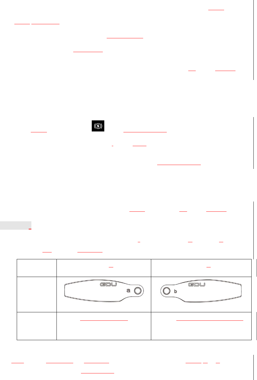
Propellers
The GDU O2system is provided with folding propellersdivided into Type Aand Type B,
corresponding to the different rotational directions of the motor.
Propeller
Type A
Type B
Schematic
Diagram
Installation
location
On the clockwise rotating motor
shaft
On the counterclockwise rotating
motor shaft
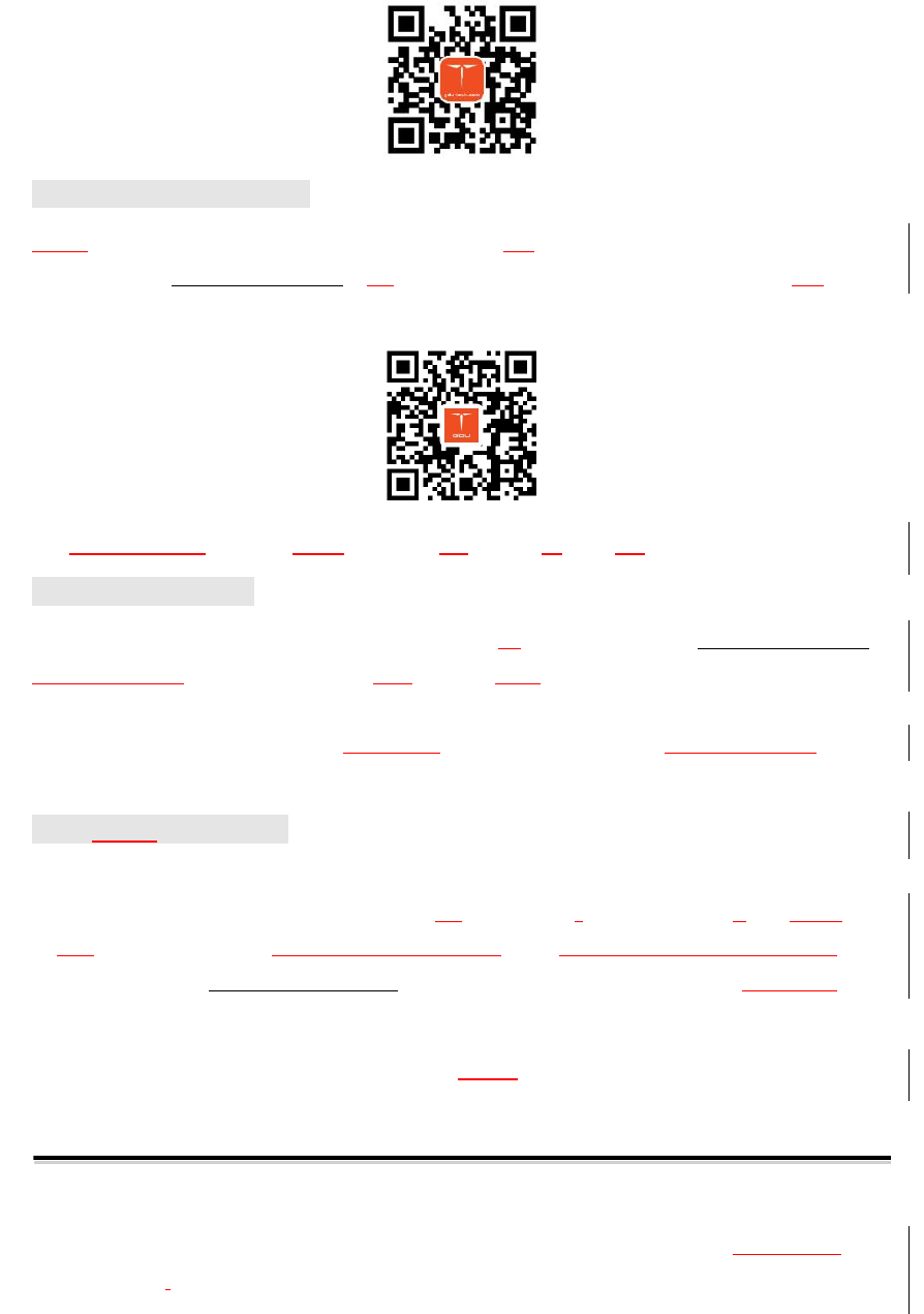
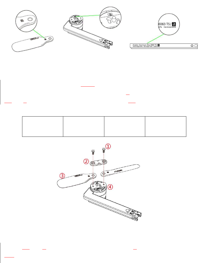
Propeller Disassembly
The base of blade, the motor, and the arm’s inner surface are marked with either A or B. The
letters on these three parts must match during the installation process.
23
The process of propeller installation is as follows. First, select the same type of propeller as per
the letter on the motor. With the letter facing upwards, press the blade into the clamp. Then press
the clamp into the slot of the motor shaft, and turn the Type Apropeller leftwards 45 degrees and
the Type Bpropeller rightwards 45 degrees, until the holes at the two ends are aligned with the
stop pins. Finally, tighten the screws.
Screw
Clamp
Blade
④Motor shaft
slot
The process of propeller disassembly is as follows. First, remove the screws. Then rotate the
clamp of the Type Apropeller rightwards or the clamp of Type Bpropeller leftwards 45 degrees,
then remove the clamp. Finally, remove the propeller.
24
Anti-Shooting Propellers
The anti-shooting propellers provide a safety guarantee in addition to screw locking. Even if the
screws are loose, the anti-shooting propellers prevent the propellers from being released. The hook
of the propeller clamp fits with the slot of the motor shaft. The motor shaft cannot be removed
until the clamp is rotated to a proper angle.
Battery
The product is provided with a high-performance smart lithium battery (4000mAh and 11.4V).
Power On and Off
Press the power switch once and hold for 2 seconds to power on/off the aircraft.
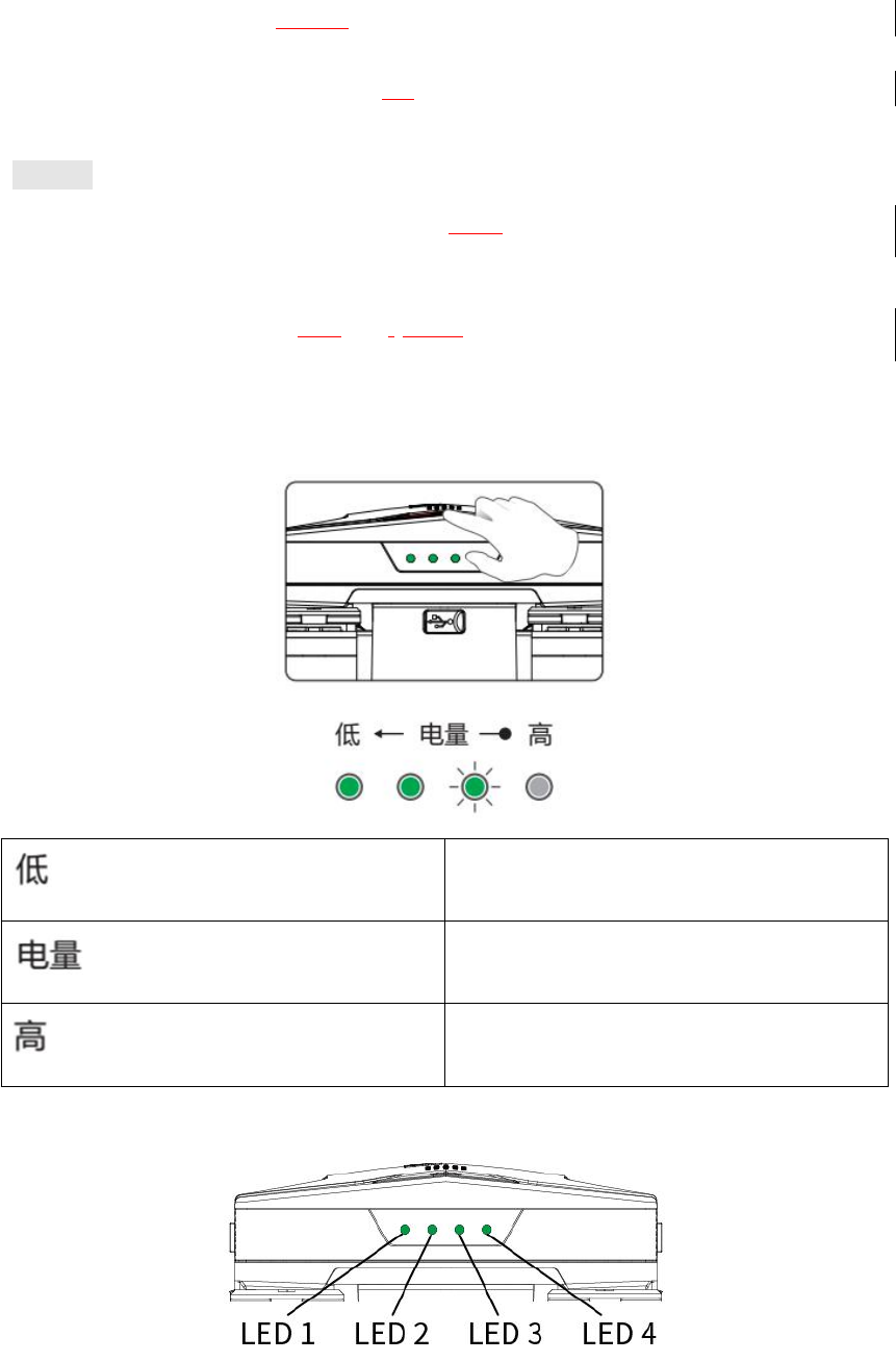
Power Check
Press the power switch once to check the remaining power when the aircraft is OFF.
Low
Power
High
Power Indicator
25
LED1
LED2
LED3
LED4
Current Power
Flashing
fast
None
None
None
0-5%
Flashing
None
None
None
6%-25%
ON
Flashing
None
None
26%-50%
ON
ON
Flashing
None
51%-75%
ON
ON
ON
Flashing
76%-100%
ON
ON
ON
ON
100%
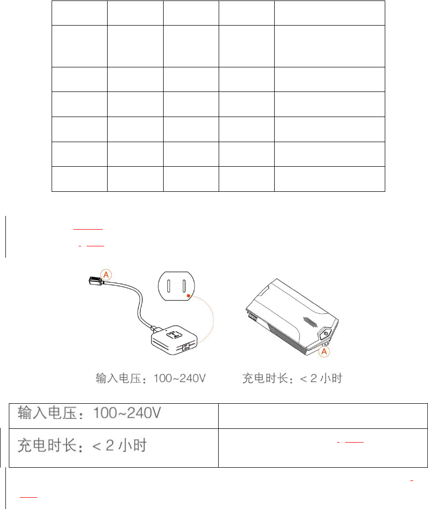
Charging
Power off the aircraft. Remove the battery and charge with a designated charger. The charging
time is within 2 hours.
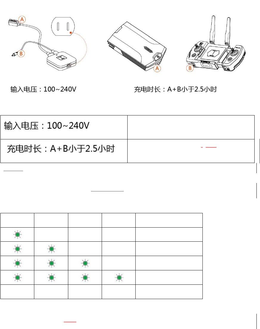
Input voltage: 100-240V
Charging time: less than 2 hours
If the battery and remote controller are charged at the same time, the charging time is within 2.5
hours.
26
Input voltage: 100-240V
Charging time: less than 2.5 hours (A+B)
During the charging process, the charger indicator will flash. If the indicators flash green, it means
that the battery is being charged. If the indicator is OFF, it means that the battery has been fully
charged, and the charger should be immediately disconnected.
Charging Indicator
LED1
LED2
LED3
LED4
Current Power
Ο
Ο
Ο
0%-25%
Ο
Ο
25%-50%
Ο
50%-75%
75%-100%
Ο
Ο
Ο
Ο
Full
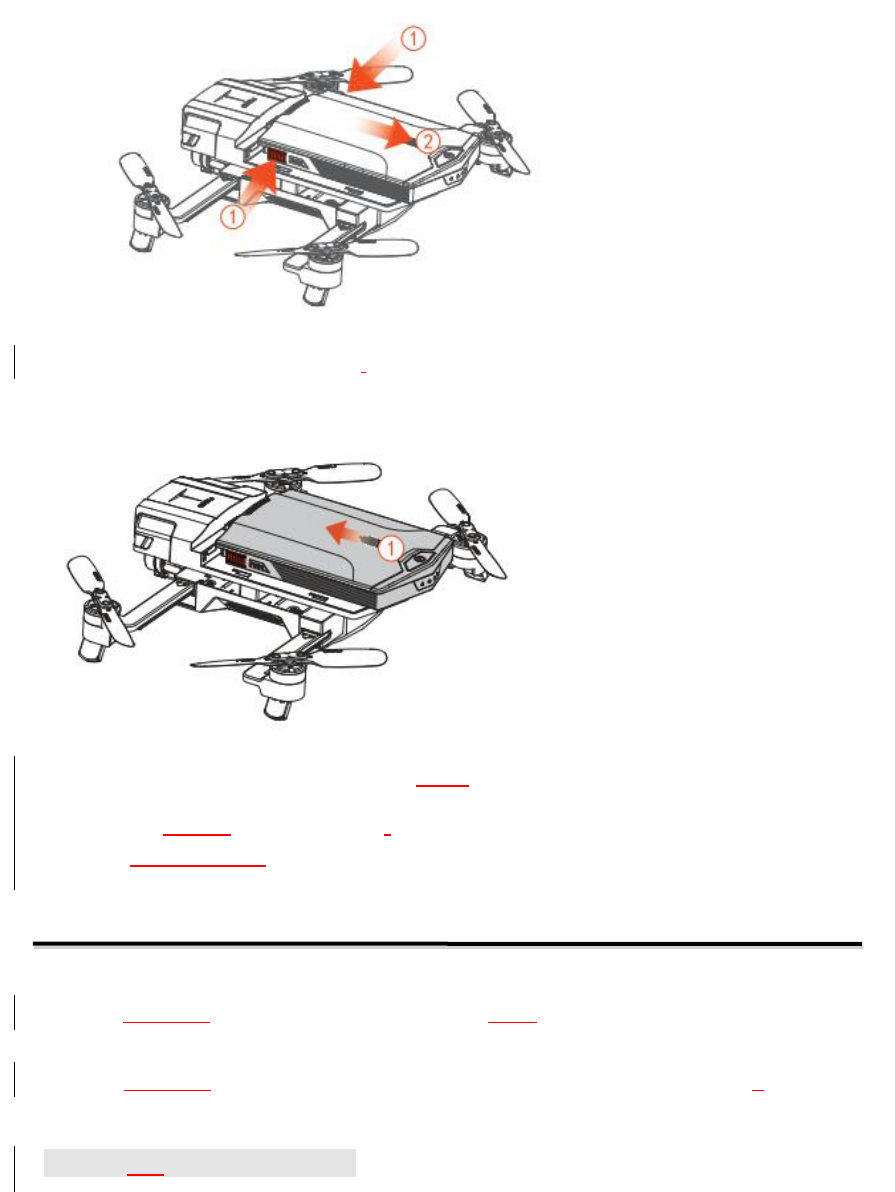
Battery Removal
(i) Press the buttons on both sides at the same time. (ii) Remove the battery by pulling backwards.
27
Align the battery with the locking slot of the body, and insert the battery by pushing
forwards.
※Insert or remove the battery with the aircraft powered OFF. After flight, remove the battery.
※The battery contains hazardous chemicals. Prior to use, please carefully read the Battery Safety Guide
and the warnings written on the battery.
Remote controller
The remote controller of GDU O2product is equipped with the advanced automatic
frequency-switching wireless communication system. Your mobile phone can be easily inserted
on the remote controller. The wireless HD video transmission system is integrated in the remote
controller. Using the GDU Mini App, the user can watch HD real-time footage on their mobile
phone. The parameters of the aircraft can be fully displayed on the screen.
Prepare the Remote controller
Power on and off
Press the remote controller until you heard the prompt tone to power on/off the aircraft.
Power Check

28
Press the remote controller for 1 second in the OFF state, and check its power on the left side of
the screen. If the aircraft is connected to the remote controller, check the power of the aircraft on
the right side of the screen.
Description of Remote controller Screen
Connection of Remote controller and Aircraft
Charging of Remote controller
Only charge the remote controller in its OFF state. Check whether the remote controller is fully
charged according to the charger’s indicator light color. If the power indicator flashes in red, it
means that the remote controller is being charged. If the power indicator shows a steady ON in
green, it means that the remote controller has been fully charged. The charging duration is
generally within 2 hours.Afully charged remote controller can be used for about 1.5 hours.
※Please use designated chargers to charge battery and remote controller. GDU will not be responsible
for any damages or faultscaused by not using original accessories.
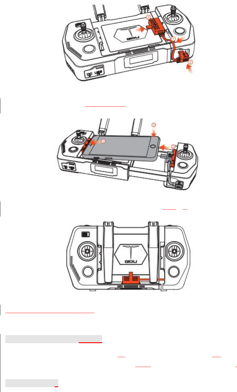
Mobile Phone Installation
1. Use the appropriate data cable with micro USB side inserted into the slot.
29
2. Adjust the length of remote controller, clamp the mobile phone into the appropriate position,
and connect the other end to the mobile phone’s charging interface.
3. After flying, remove the mobile phone and fix the data cable back into the slot.
The remote comes equipped with a Lightning cable by default. If requires, please replace it with
the Micro USB cable.
HD Video Transmission System
The GDU O2series product is provided with an HD video transmission module for the real-time
transmission of 720P HD images. The transmission range is 1km for O2and 7km for O2Plus,
Gimbal Camera
The control dial wheels on the controller controls yaw and pitch. Back-to-center could let the
30
gimbal return to the initialization place. The “Photo” button and “Video” buttonsare used for
controlling the camera in real-time.
※The Back-to-center button can be customized.
※The gimbal camera can also be controlled by the GDU Mini App. See details in APP.
Aircraft Control
The remote controller supports three modes: American (Mode 1), Japanese (Mode 3) and Chinese
(Mode 2). The control sticks are defined as follows.
1. American (Mode 1): throttle and rotation on left stick, and left/right and forward/backward on
right stick.
Left stick
Right stick
Up
Down
31
Turn left
Turn right
Forward
Backward
Left
Right
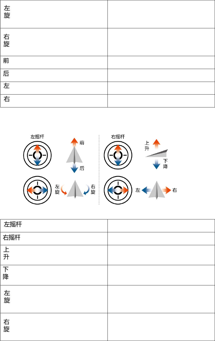
2. Japanese (Mode 3): forward/backward and rotation on left stick; throttle and left/right on right
stick.
3.
Left stick
Right stick
Up
Down
Turn left
Turn right
32
Forward
Backward
Left
Right
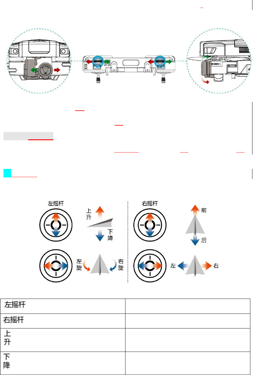
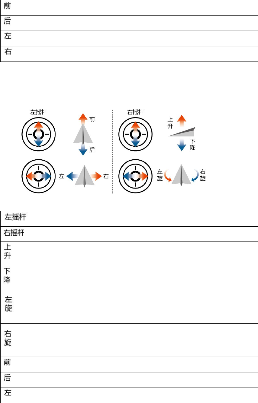
4. Chinese (Mode 2): forward/backward and left/right on left stick; throttle and rotation on right
stick.
5.
Left stick
Right stick
Up
Down
Turn left
Turn right
Forward
Backward
Left
33
Right
The default mode is American (Mode 1). You can change the operating mode of the remote
controller in the Control settings interface of the GDU Mini App.
Frequency Matching
Frequency matching of the remote controller and built-in receiver has been performed before
delivery, so the user can directly access the remote controller. If the aircraft or remote controller is
replaced, frequency matching should be redone. It is not necessary to connect the mobile phone to
the remote controller during frequency matching.
Frequency matching steps:
1. With the remote controller OFF, press the Return button and power switch at the same time.
The remote controller will utter aprompt sound and “MATCHING...” will appear on the screen.
2. Turn on the power supply of the aircraft.
3. Connect the mobile phone to the aircraft. WIFI network: GDU-02-A-xxx; password: 12345678.
4. Run the GDU Mini App and click “Start shooting” to enter the flight interface.
5. Click “Settings” in the upper right corner. Then click “Remote controller matching” in the
“Control settings” interface.
6. If matching succeeds, “MATCH SUCCESS” will appear on the remote controller screen.
7. If matching fails, repeat the above steps.
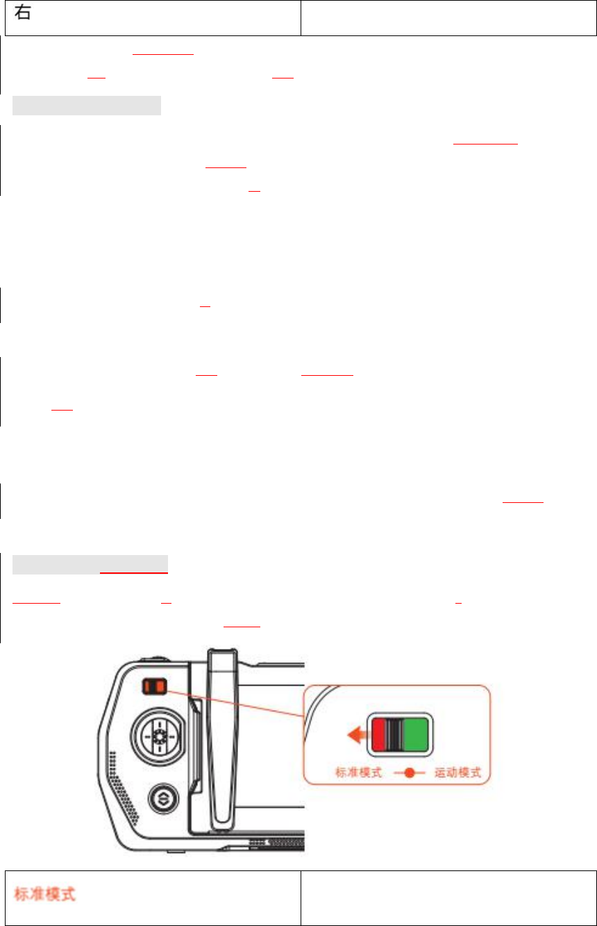
Flight Mode Selection
Use the remote controller’s flight mode switch to switch among flight modes. Push the switch to
the left to enable standard mode and to the right to enable sport mode.
Standard mode
34
Sport mode
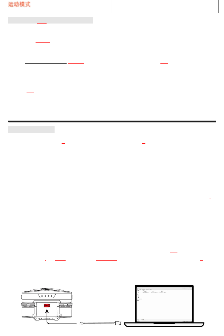
Upgrading the Remote controller
Upgrading the remote controller includes upgrading of both the operation system and the video
transmission system.
Operation system upgrading: download “O2remote controller upgrade software” from the official
website www.gdu-tech.com to your PC, connect the remote controller to the PC, open the
software,and click “Upgrade”.
Video transmission upgrading: once the information of the WIFI video transmission version is
detected, the GDU Mini APP will automatically remind the user to upgrade the version. The user
can upgrade the video transmission version by following the prompts.
Gimbal Camera
Camera Overview
GDU O2is equipped with aSony 1/3 inch CMOS camera, with aresolution up to 13,000,000
pixels. With alow-distortion wide-angle lens of 25.5mm equivalent focal length, premium
images can be captured.
The camera supports 4K video recording at 30 fps and photographs of amaximum of 13M
pixels. Using the advanced image processing technology, high-quality videos and photos can
be provided. The camera also supports various shooting modes, including single shooting
(12MP), time-lapse shooting, continuous shooting (12MP/5 photos/second), timed shooting,
and zoom shooting.
HD videos can be previewed in real-time through the GDU mini App.
Memory
The capacity of the built-in memory is 16G for the O2and 32G for the O2Plus. The videos and
photos in the memory can be copied by connecting one end the USB cable to the PC and the other
end to the aircraft,and then turning on the aircraft’s power. The user can also download their
videos and photos from the media interface of the GDU Mini APP.
35
※In order to ensure camera stability, the duration of any single recording should be less
than 20min
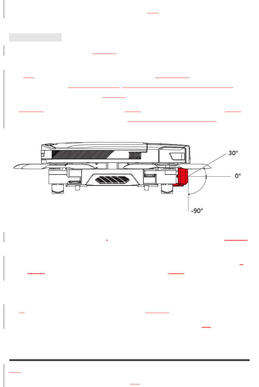
Gimbal Overview
The three-axis stabilized gimbal provides a stable platform for the camera, so as to shoot high
quality images during high-speed flight.
With this high-precision three-axis anti-shake gimbal, the variations in accuracy will be 0.05°
or less. Even in case of heavy maneuvering,photography will remain accurate to within 0.1°
or less, thus preventing shaking and enabling HD video recording and image acquisition.
The aircraft’s orientation angle and roll angle range are -30° to +30°, and pitch angle range is
-90° to +30°, which ensures shooting stability regardless of the aircraft’s motions.
※Before takeoff, keep the aircraft on flat,broad ground and prevent the gimbal camera from coming in
contact with any object.
※If the aircraft is kept on uneven ground or grass and the gimbal camera is subject to collision against
any foreign object or large external force, motor stalling and other errors may occur.
※Flight in fog or clouds may result in condensation or damage the aircraft and camera. In this case, dry
the gimbal camera and drone immediately.
※Ashort vibration prompt after startup is normal. Do not physically turn the gimbal camera.
※Before flight, check whether the lens is clean. Do not touch the lens by hand. Wipe any stains with
scratch free, lint free cloth.
GDU Mini App
The GDU Mini APP is application software designed by GDU for O2series products. The
user can use the software to control the aircraft, the gimbal camera and its gimbal, thus
36
enabling the functions of flight control, shooting/recording, course planning, parameter
settings,media sharing, etc.
The GDU Mini APP is composed of four modules: Drone, Media, Explore and Me.
※The interfaces and functions of the app will be regularly upgraded. Please refer to the latest APP
version.
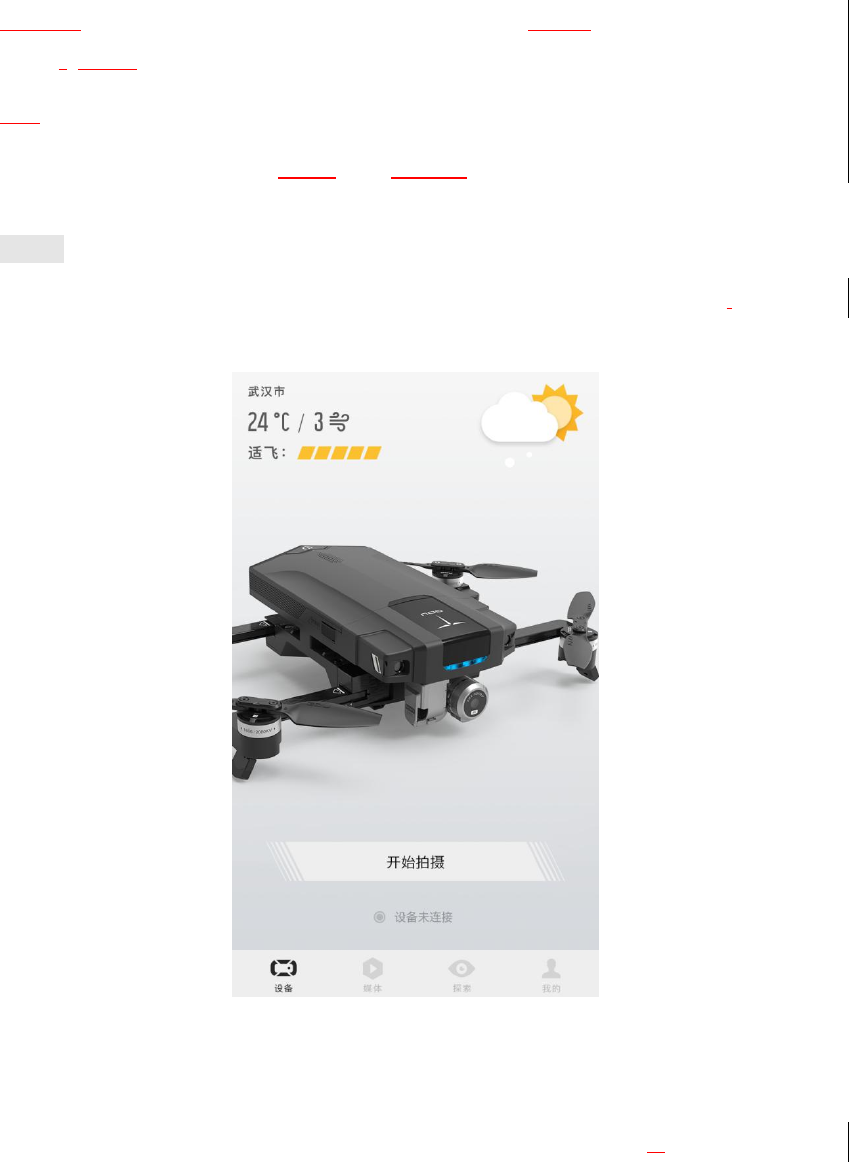
Drone
The Drone page includes: real-time weather, flight index view, aircraft appearance,and
aircraft connection status. Click “Start” to enter the flight interface.
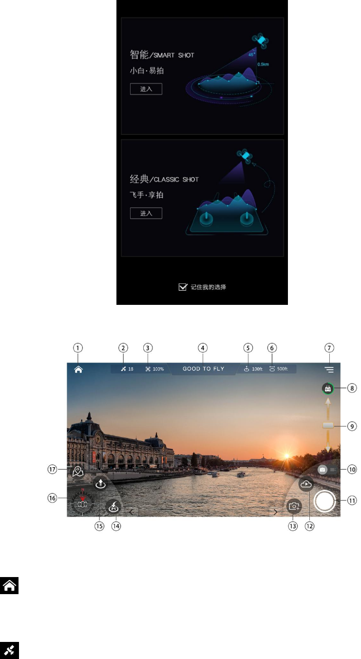
Flight Interface
Before entering the flight interface, select Smart shot or Classic shot. These are provided for
different users, and their functional interfaces are difference.
37
Classic Shot Mode
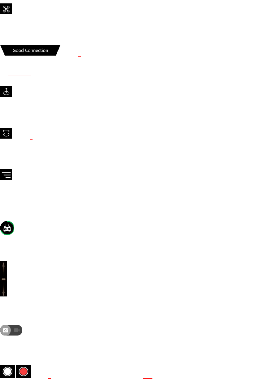
①Home
: click to return to the Home page of APP.
②GPS status
: shows the number of GPS.
38
③Aircraft power
: showsthe remaining power of the aircraft.
④Aircraft connection status
: showsthe connection status of the aircraft.
⑤Altitude
: showsthe current flight altitude.
⑥Flight distance
: showsthe current flight distance.
⑦Settings
: click to enter the system setting interface of the aircraft, including control settings, flight
settings, video transmission settings, camera settings and general settings.
⑧Remote controller power
: show the remaining power of the remote controller.
⑨Gimbal pitch adjustment
: adjust the pitch angle of the gimbal camera.
⑩Photo/video switching
: click it to switch between photo/video modes.
⑪Photo/video button
/ : showsthe current shooting mode: photo or video.
⑫Cloud media
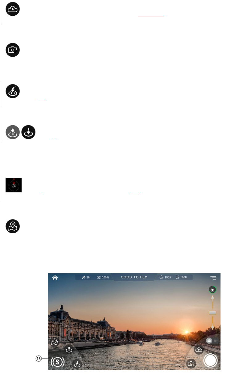
39
: view the media files in the memory of the currently connected aircraft.
⑬Camera settings
: click to open the camera function parameters, which can be adjusted.
⑭RTH
: click to return and land.
⑮Auto take-off/Vertical landing button
/ : showsthe takeoff button before takeoff ; shows vertical landing button after
takeoff.
⑯Compass
: showsthe current orientation and heading.
⑰Switch to map
: click to switch to the map interface.
Smart Shot Mode
⑱Smart function
40
: main functions of the flight interface in smart shot mode include: Follow Me, Vision
circle, Point of Interest, Gesture Shot, Dronie, Rocket, etc.
※See the smart flight function for specific operations.
※The smart functionswill be upgraded continuously. Please refer to the latest APP version.
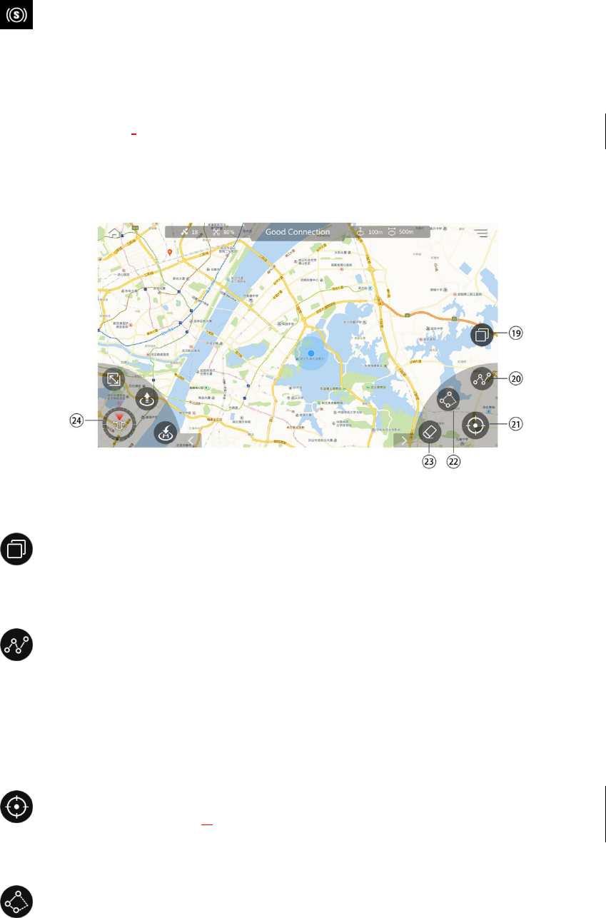
Map interface:
⑲Map switching 切换地图
: click to change the map display among 2D map, satellite map and hybrid map.
⑳Waypoint
: click to activate the waypoint function, where you can set and upload flying mark
points that the aircraft will follow.
㉑Positioning
: click to locate the aircraft’s current position.
㉒Electronic fence
: the aircraft will fly safely within the set electronic fence.
㉓Clear
41
: click to clear any non-uploaded waypointsor electronic fencesin the map interface.
㉔Switch to flight interface
: click to return to the flight interface.
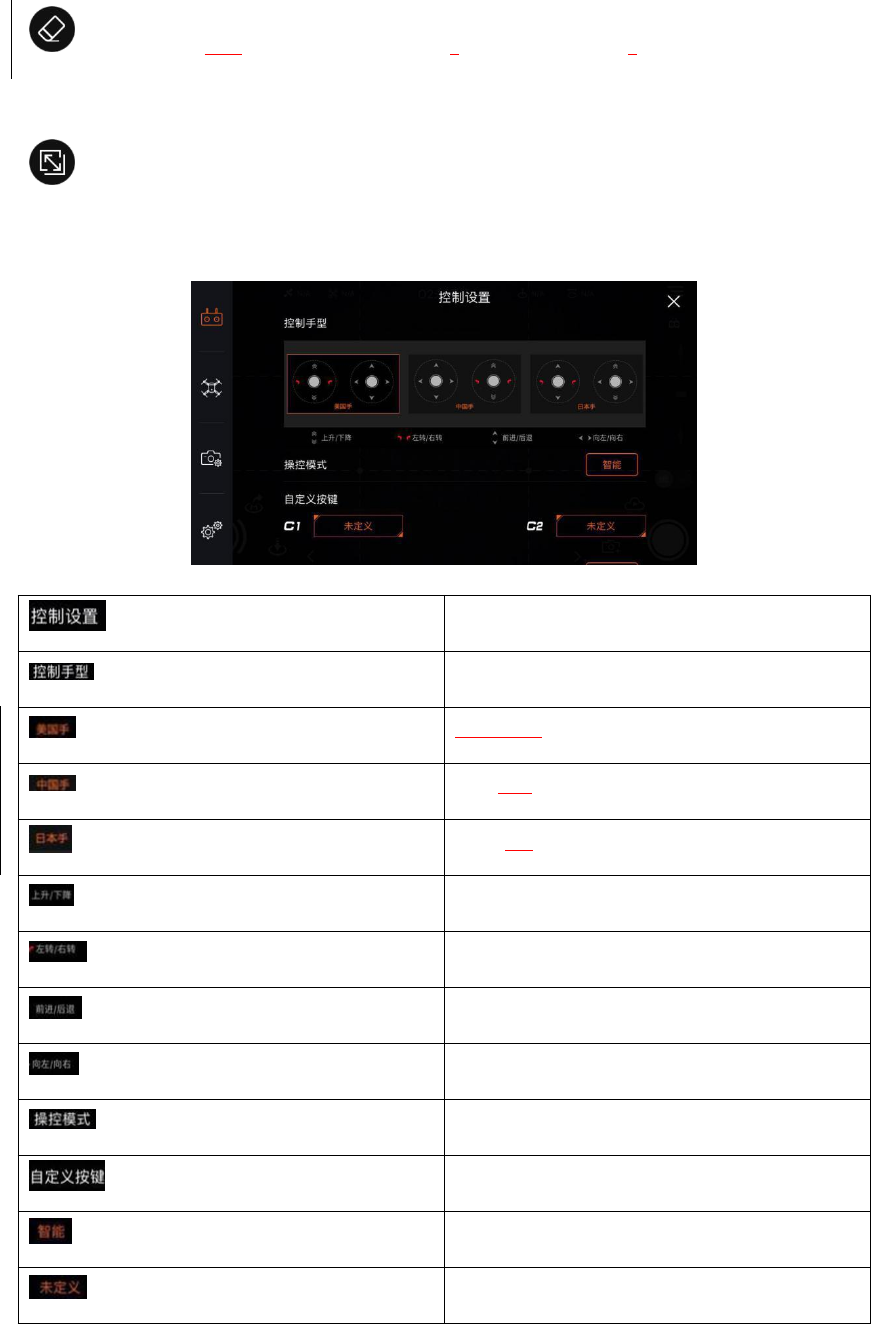
Settings:
Control Settings
Control mode
American (Mode 1)
Chinese (Mode 2)
Japanese (Mode 3)
Up/Down
Turn Left/Right
Forwards/Backwards
Left/Right
Flight mode
Customizable buttons
Smart
Undefined
㉕Control settings
42
Switch the control mode, customize C1\C2 buttons and match RC with drone.
㉖Flight settings
Set altitude/distance limit, return altitude and visual obstacle avoidance.
㉗Camera settings
Set preview resolution ratio, video resolution ratio, photo resolution ratio and storage.
㉘General settings
Set the grid, sound, param units, magnetometer, calibrate map coordinates and view drone
information.
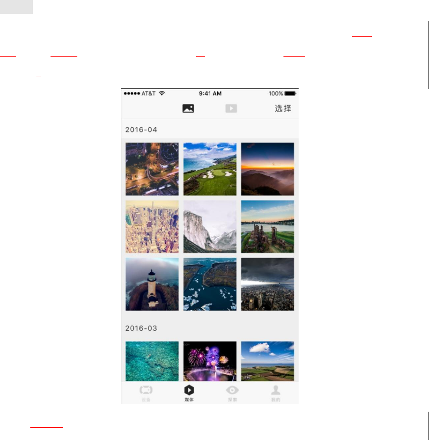
Media
The user can view downloaded photos and videos through the media center, or edit photos
and videos using the appropriate editor. These edited works can then be shared to social
networks.
Photo editing:
Retouch and Color Correction
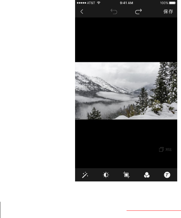
43
11.5
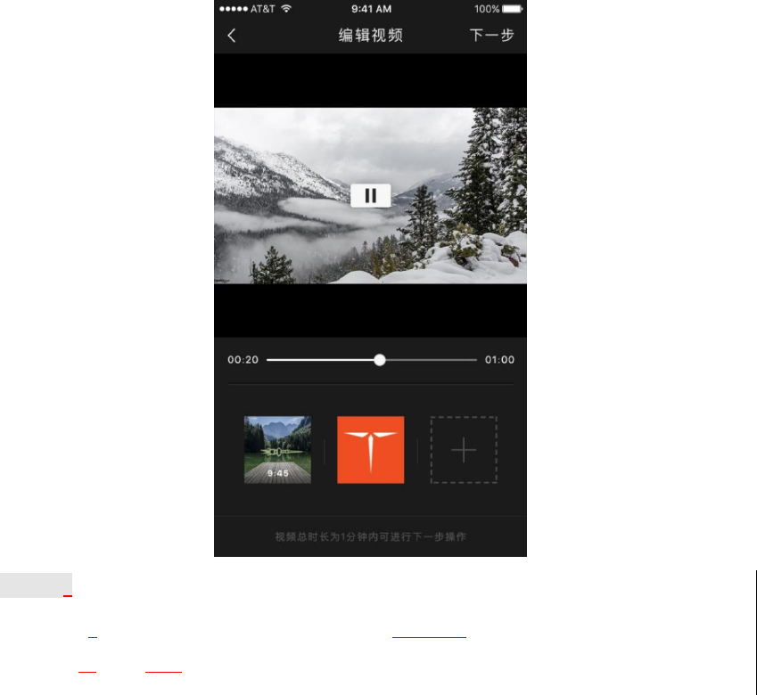
Video editing:
Single-video editing, multi-video stitching, and adding video themes (filter + music)
44
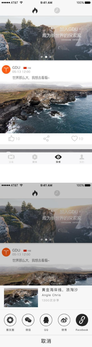
Explore
The Exploreinterface shows the wonderful aerial artworks uploaded by the user. After
uploading is successful, the works will be synchronously shared on social media platforms.
45
Sharing:
46
※The supported third-party platforms will be added continuously as the app is upgraded. Please refer to
the latest APP vision.
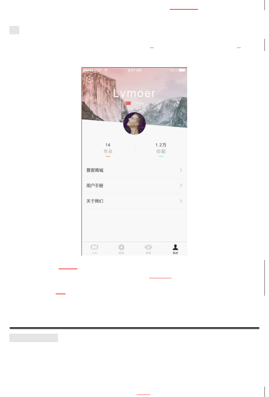
Me
In the GDU Personal Center, the user can modify their personal information, view their
published works and collected favorites and visit the Official GDU Store.
※The language of the app interface should be the same as the system language of the mobile device.
Change the system language of the mobile device before changing the interface language.
※At present, the app interface only supports Chinese Simplified and English. The language package will
be added later, and please refer to the latest APP version.
Flight
Preflight Check
Check all parts of the aircraft before each flight. If there is any damage, please repair/replace
before trying to fly the aircraft
Check whether the aircraft battery, remote control and mobile phone have sufficient power.
Ensure that the arm and landing pad have been fully extended in place and the propeller has
been installed securely.
47
Check whether the remote controller is properly connected to the aircraft.
Always operate with the latest firmware. And check whether the GDU Mini APP and the
remote controller are connected normally.
Check whether the motor and gimbal camera work normally after the aircraft is started.
Magnetometer Calibration
Calibrate the magnetometer according to the following procedures in an open space. For more
information, watch the related teaching video.
Steps:
1. Power on the remote control and then the aircraft, then connect the mobile phone to the
remote controller. At this time, the aircraft will begin its self-check, accompanied by a beeping
sound.
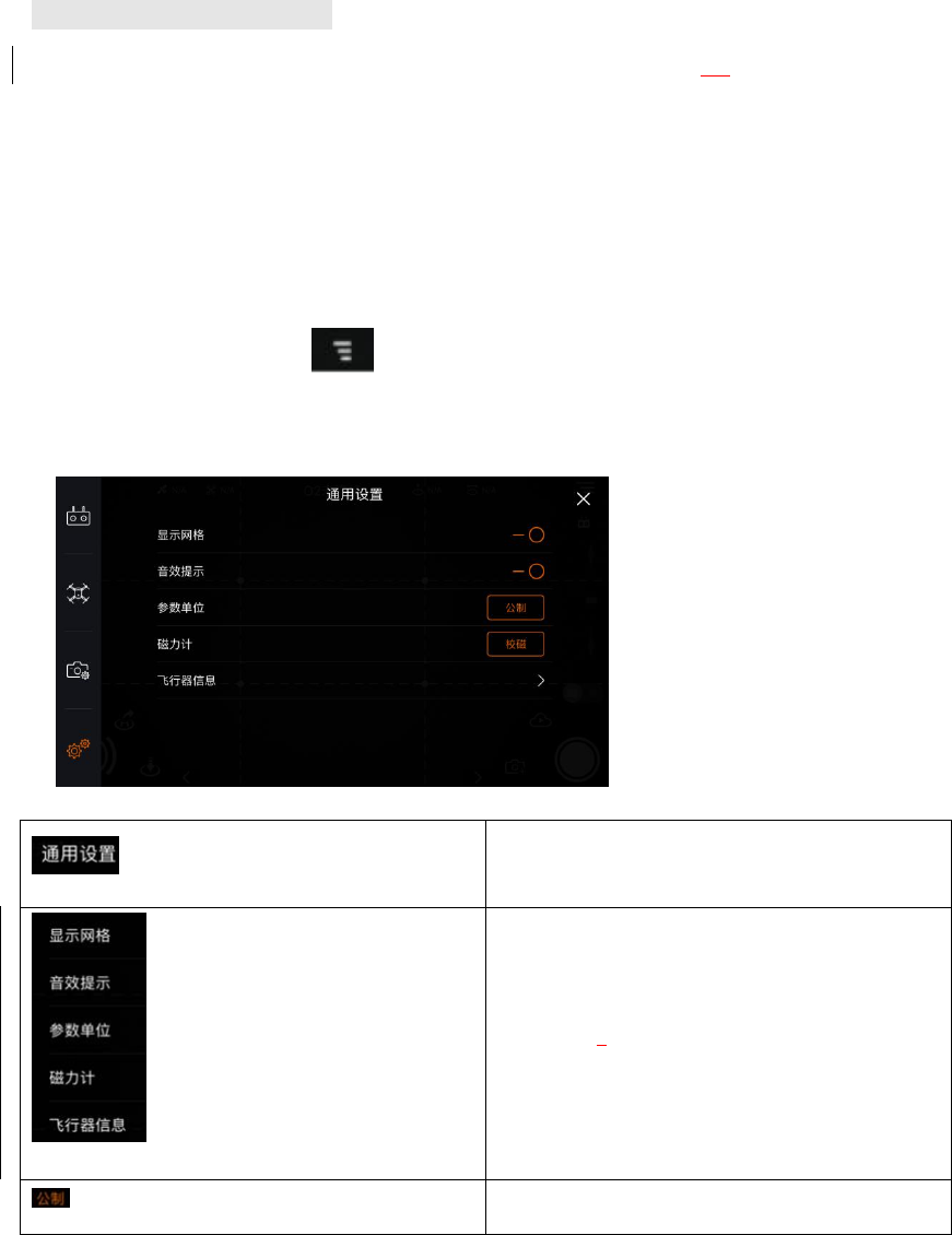
2. After the beep stops, click on APP, and select page of “General Settings”; click
“Calibrate” on the right; it enters into mode of compass calibration when the yellow light keeps
on, the magnetometer calibration mode is enabled.
General Settings
Grid
Sound
Param units
Magnetometer
Drone information
Metric/Imperial
48
Calibrate
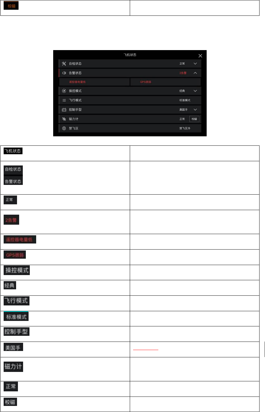
Drone Status
Self-check status
Warmings
Normal
2 alarm
Low controller battery
Weak GPS signal
Flight mode
Classic
Flight mode
Standard mode
Control Mode
American (Mode 1)
Magnetometer
Normal
Calibrate
49
NFZ (No Fly Zone)
Outside of the NFZ (No Fly Zone)
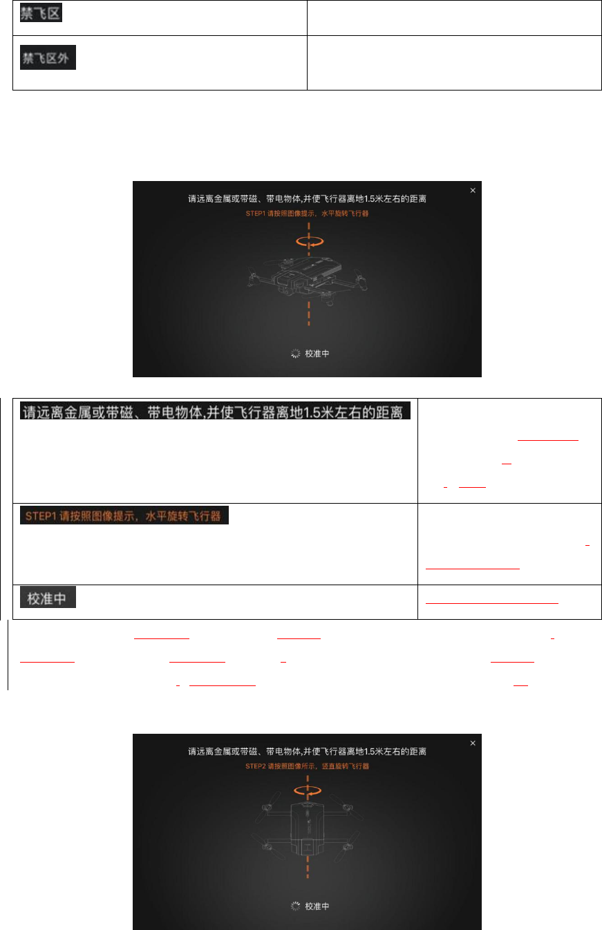
3. Start magnetometer calibration. Hold the aircraft and rotate it clock-wisely and
horizontally. Observe the color of the LED indicator light in the aircraft and go to the next
step when the LED indicator turns solid white light. Otherwise, please return to the step 2.
Keep the aircraft away from
metal, magnetic materials,
or live objects, and at about
1.5 meters above the ground.
STEP 1: horizontally rotate
the aircraft according to the
displayed image prompts.
Calibration in progress
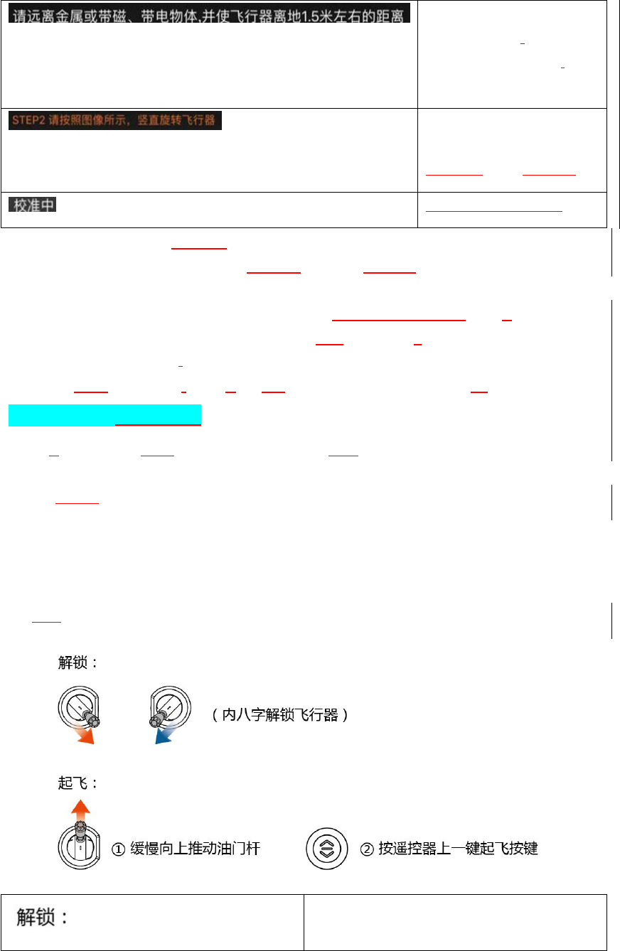
4. Hold the aircraft carefully. With the nose facing downward, rotate the aircraft clockwise
vertically and observe the aircraft’s indicators. If the tail indicator is solid green, vertical
magnetometer calibration is successful. Otherwise, magnetometer calibration failed, please
return to Step 2.
50
Keep the aircraft away from
metal, magnetic,or live
object and at about 1.5 m
above the ground.
STEP 2: vertically rotate the
aircraft according to the
displayed image prompts.
Calibration in progress
※Do not move the aircraft while it is inself-check.
※Calibrate the magnetometer before the aircraft’s first use or after any significant change in flight area.
Otherwise, the aircraft will not be unlocked for flight.
※Calibrate the magnetometer in cases of serious drift or if the aircraft fails to fly along astraight line.
※Do not calibrate the magnetometer indoors or near large metal objects, or in the place with strong
electric and magnetic fields.
※Do not touch mobile phones, watches, keys, or other metal objects while calibrating the magnetometer.
General Flight Operations
Select aflat and open space, and turn on the power of both the remote controller and aircraft. After
the magnetometer is calibrated successfully, the indicator of the aircraft will become green. The
aircraft should be kept horizontal, and the user should face the tail of the aircraft.
Manual Take-off/Landing
Unlock the aircraft by pushing the sticks down inward. After the motor is started, release two
sticks at the same time, and slowly push the throttle up or press the Takeoff button. The aircraft
will then take off.
Unlock:
51
(Unlock the aircraft by pushing the sticks down
inward)
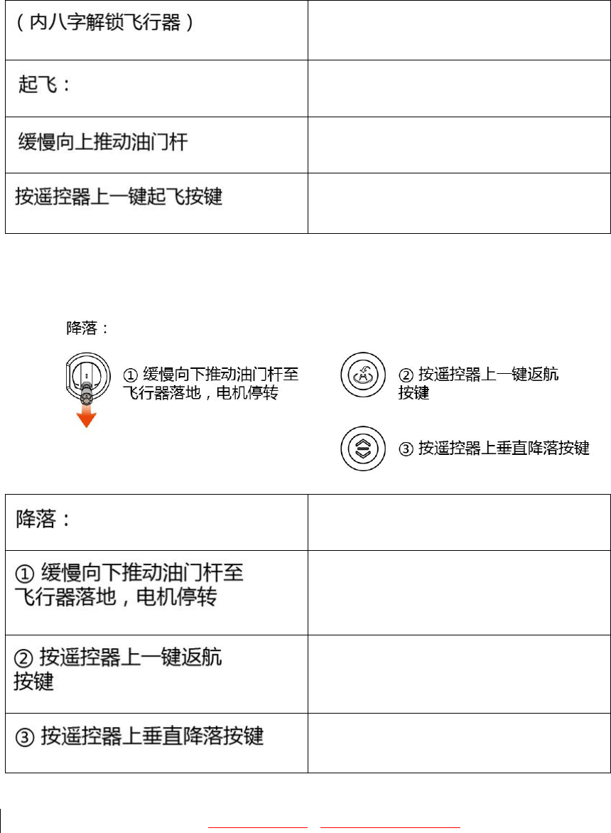
Takeoff:
slowly push the throttle up
Press the Takeoff button on the remote
controller
During the flight, push the throttle downward slowly and the aircraft will land slowly. At this time,
push the throttle to its lowest place and hold for two seconds. The motor will stop and then loosen
the throttle to lock the aircraft.
Landing:
(i) Slowly push the throttle down until the
aircraft lands onto the ground and the motor
stops running.
(ii) Press the RTH button on the remote
controller.
(iii) Press the Vertical Landing button on the
remote controller.
Automatic Take-off/Landing
The aircraft must fly within 80m of the controller if being piloted using the GDU Mini APP.
Operating steps:
1. Power on the aircraft, and connect the mobile phone to aircraft. WIFI: GDU-02-A-xxx;
password: 12345678.
2. Run GDU Mini APP. Click “Start” to enter the flight interface.
52
3. Conduct pre-flight check according to the prompts.
4. Press the Takeoff button and confirm that the safety takeoff conditions have been met.
The aircraft will hover at 1.5 meters above the ground. At the same time, the virtual sticks will
appear in the interface.
Landing
1. Click the RTH or Vertical Landing button and confirm that the safety landing conditions
have been met before landing.
2. The user can click “Ⓧ” in the screen to exit landing.
3. The aircraft will land on the ground, and the motor will automatically stop running.
4. Power off the aircraft.
※In case of emergency in the air, the stick can issue an emergency stop, which will result in the aircraft
falling to the ground.
※If flight is controlled by the controller, it can be connected to a mobile phone for real-time viewing of
the flight interface.
※The GDU Mini APP is only applicable to O2 products.
※Before the flight, please put the head of the aircraft forward and keep over 10 feet away from the
aircraft.
※Do not unlock the aircraft on steep slopes or hillsides.
Technical Parameters
●Aircraft
Takeoff weight (excluding hood) 730g
Takeoff weight (including hood) 846g
Maximum ascend speed 5m/s (sport mode)
Maximum descend speed 3m/s
Maximum horizontal speed 15m/s (sport mode, in windless condition above
sea level)
Maximum flight altitude 3500m
Maximum hovering time 20min (in windless condition)
Operating temperature 0℃to 40℃
Satellite positioning module GPS/GLONASS, dual-mode
●Gimbal camera

53
Controllable angle range Pitch: -90° to 30°
Roll: -30° to 30°
Yaw: -30° to 30°
●Forward vision system
Sensing range 0.5-15m
Operating condition Obstacleswith clear texture and adequate lighting
conditions (>15lux)
● Downward vision system
Speed measurement range Flight speed: ≤10m/S (at 2m height, with adequate
light)
Height measurement range 0.3-3 m
Accurate hovering range 0.3-13 m
Operating environment Clear texture on the ground and adequate lighting
conditions (>15lux)
● Camera
Image sensor 1/3-inch CMOS with 13M effective pixels
Lens FOV 79.8°equivalent focal length 25.5 mm F/2.2
Distortion <1.5%
ISO range Auto 100 - 1600
Electronic shutter speed Auto
Maximum photo resolution 4208*3120
Video resolution 4K: 3840×2160 @ 25 fps
1080P: 1920×1080 @ 30fps
720P: 1280×720 @ 30fps
Image format JPG
Video format MP4
Built-in memory: 16G (O2)or 32G (O2Plus)
● Remote controller
Operating frequency 5.8GHz (O2)or 2.4GHz (O2Plus and O2X)
Video transmission distance 1km (O2) or 7km (O2Plus)

Operating temperature 0 to 40℃
Battery 1200mAh
Operating voltage 7.6V
USB type Lightning, Micro USB and Type C
● Charger
Voltage 13.05 V
Rated power 39.15 W
● Battery
Capacity 4000mAh
Voltage 11.4 V
Type LiPo 3S
Energy 45.6Wh
Overall weight About 283g
Maximum charging power 78W
FCC STATEMENT :
This device complies with Part 15 of the FCC Rules. Operation is subject to the following
two conditions:
(1) This device may not cause harmful interference, and
(2) This device must accept any interference received, including interference that may
cause undesired operation.
Warning: Changes or modifications not expressly approved by the party responsible for
compliance could void the user's authority to operate the equipment.
NOTE: This equipment has been tested and found to comply with the limits for a Class B
digital device, pursuant to Part 15 of the FCC Rules. These limits are designed to provide
reasonable protection against harmful interference in a residential installation. This
equipment generates uses and can radiate radio frequency energy and, if not installed
and used in accordance with the instructions, may cause harmful interference to radio
communications. However, there is no guarantee that interference will not occur in a
particular installation. If this equipment does cause harmful interference to radio or
television reception, which can be determined by turning the equipment off and on, the
user is encouraged to try to correct the interference by one or more of the following
measures:
Reorient or relocate the receiving an tenna.
Increase the separation between the equipment and receiver.
Connect the equipment into an outlet on a circuit different from that to which the
receiver is connected.
Consult the dealer or an experienced radio/TV technician for help.
This device comply with FCC SAR requirements. The highest reported 1g-SAR for body is 1.051 W / Kg