GE Harris Aviation Information Solutions GDL-002 Radio Module and external Power Amplifier User Manual
GE Harris Aviation Information Solutions, LLC Radio Module and external Power Amplifier Users Manual
User Manual
E
D
O
C
E
G
A
C
O
N
G
W
D
VE
R
HS
5
4
2
7
7
NONE
7
5
2
4
0
0
7
7004257
1of33
77245
AEROSPACE
SYSTEMS DIVISION
MELBOURNE, FLORIDA 32902
+ + +
SYS ENGR
APPROVAL - DFTG
RELIABILITY
PROJ ENGR
ENGR
DRAWN BY
CONTRACT NO.
APPROVAL
CONFIGURATION
QA
MFG ENGR
ELEC ENGR
CHK BY
UNLESS OTHERWISE SPECIFIED
DIMENSIONS ARE IN INCHES
AND INCLUDE APPLIED FINISH
TOLERANCES
2 PLACE 3 PLACE ANGLES
SCALE
TITLE
SIZE
A
CAGE CODE DWG NO. REV
E+
SHEET
REVISION
INDEX
THIS DRAWING IS
PREPARED IN
ACCORDANCE WITH
MIL-STD-100
DESCRIPTION
DATE APPROVEDREVUSED ON
NEXT ASSY
DASH NO.
APPLICATION REVISIONS
GROUND DATA LINK SYSTEM
B757 INSTALLATION
US AIRWAYS TRIAL PROGRAM
Rev E+
CHNG BY CHK BY ECO NO.
ºService Bulletin
Ground Data Link - B757
E
D
O
C
E
G
A
C
ON
G
W
D
H
S
VE
R
2
NONE
7
5
2
4
0
0
7
7004257
77245
HARRIS CORPORATION
GOVERNMENT AEROSPACE SYSTEMS DIVISION
MELBOURNE, FLORIDA 32902
REV
E+
SIZE
A
CAGE CODE DWG NO.
SCALE SHEET
54
27
7
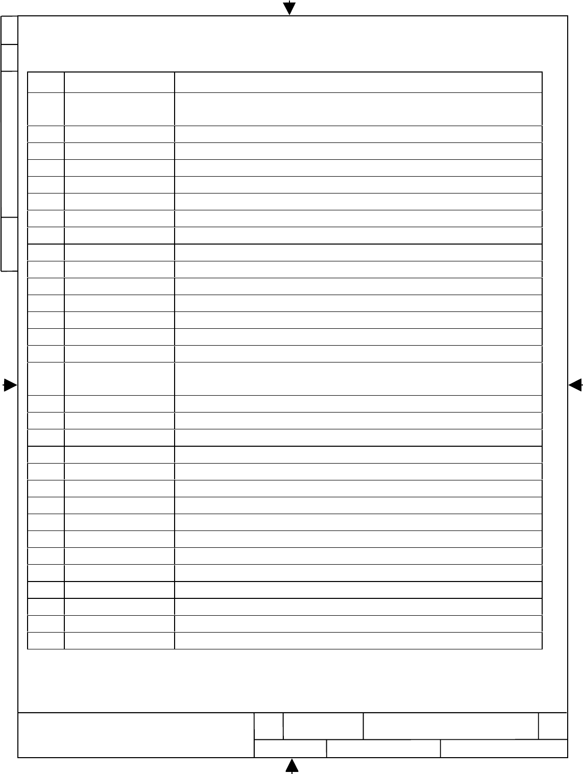
Revisions Record
Rev. Paragraph Change
A7.f, 7.k, 7.l, 7.m, 11 Change rivet from NAS1097AD5-5 and NAS1097AD5-6 to MS14218E4-4 and
MS14218E4-5
AFigures 7.1 Change rivet installation notes and rivet type
A12, drawing 3032703 Replace rev ‘-“ with rev “A”
B4.e Change P/N XXXXX to P/N 3032724-001
BGeneral Change “Route wire” to “Route wire using existing wire-runs where possible”
C2.c Change “P/N 3032707-101” to “3032707-001”
C11 Delete 3032721-101 and duplicate part no 3032724-001 from Installation Kit List
C11 Correct typo, Change from “BACC47CN!” to “BACC47CN1”
CGeneral Change “3032712-101” to “3032712-appropriate dash no.”
DFig 7.1 Change MS14218E4-5 and E4-4 rivet to BACR15BB5D-4
DFig 7.2 Change Ms24693-C30 to MS24693-C31
DFig 7.3 Change S-2L to S-2R
DFig 7.4 Change from sta 440 to 460 and sta 460 to 480
E2.e Add #8 screws
E2.f Change quantity from 8 to 4, and “bottom” to “top”
E2.g Change screw to MS24693-C50, washer to NAS1149DN832J and nut to BACN10JC08CD.
Add “Remove three plugs at location labeled A.”
E2.j Change from “D11” to “D11A”
E2.k Add adapter plate BACA14BH22A
EFig 2.1, 2.2 and 2.3 Update figure
E4.e Change too from AD91-10-8 to M22520/1-01
E4.g , 4.f and 4 h Change “1-320551” to “1-320551-1”, add jumper wire BACJ40K5A5A6
EFig 5.1 Update figure
ETable 5.1 Update table
E5.i change from Pin A2 to Pin C2, BACC47ER1 to BACC47J1
E5.k change from Pin A3 to Pin C3, BACC47ER1 to BACC47J1
E5.m Change from TB160 to YA25
EFigure 8.1, 8.2 and 8.3 Update figures
E8.a , 8.c and 8.f Change sta 440 and sta 460 to sta 460 and sta 480
E8.d and 8.h Add pin rivet BACB30FM6-3 and collar BACC30M6 as alternate parts
E11 Update installation kit list
E12 Update drawing list
E
D
O
C
E
G
A
C
ON
G
W
D
H
S
VE
R
3
NONE
7
5
2
4
0
0
7
7004257
77245
HARRIS CORPORATION
GOVERNMENT AEROSPACE SYSTEMS DIVISION
MELBOURNE, FLORIDA 32902
REV
E+
SIZE
A
CAGE CODE DWG NO.
SCALE SHEET
54
27
7
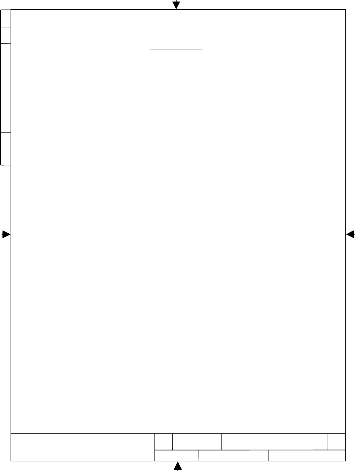
Table of Contents
1. Safety Information, Conformity Statement, and User Warnings.....................................................4
2. Remove E3-3 Shelf from the aircraft..........................................................................................5
3. Modify E3-3 Shelf ...................................................................................................................6
4. Re-install E3-3 Shelf ..............................................................................................................10
5. Install GDL Circuit Breaker and Placard in Cockpit...................................................................11
6. Install GDL Wiring in E/E Compartment..................................................................................13
7. Install Coaxial Cable Between E/E Compartment and RF Assembly............................................18
8. Install GDL Antenna Doubler Plate and GDL Antenna...............................................................21
9. Install GDL RF Assembly.......................................................................................................25
10. Install GDL Airborne Unit in GDL Tray...................................................................................28
11. Perform GDL System Checkout...............................................................................................29
12. GDL Installation Kit List ........................................................................................................31
13. Drawing List .........................................................................................................................33
E
D
O
C
E
G
A
C
ON
G
W
D
H
S
VE
R
4
NONE
7
5
2
4
0
0
7
7004257
77245
HARRIS CORPORATION
GOVERNMENT AEROSPACE SYSTEMS DIVISION
MELBOURNE, FLORIDA 32902
REV
E+
SIZE
A
CAGE CODE DWG NO.
SCALE SHEET
54
27
7
1. Safety Information, Conformity Statement, and User Warnings
a.
Safety
The FCC with its action in ET Docket 96-8 has adopted a safety standard for human exposure to radiated
frequency (RF) electromagnetic energy emitted by FCC certified equipment. This GE Harris equipment meets
the general population/uncontrolled environmental limits for Maximum Permissible Exposure (MPE) found in
FCC Bulletin OET-65 and OET-65, Supplement C. Proper installation and operation of this system according to
the instructions found in this Service Bulletin will result in human exposure substantially below the FCC
recommended limits.
To assure safe operation:
• Do not operate the system when nearby persons are within 20 cm (8 in) of the antenna
• Do not operate the system in an explosive environment
• To avoid damaging system components, do not operate the system unless the antenna(s) are connected
b.
Manufacturer’s Federal Communication Commission Declaration of Conformity Statement
This device complies with Part 15 rules. Operation is subject to the following two conditions:
1) This device may not cause harmful interference, and
2) this device must accept any interference received, including interference that may cause undesired
operation.
c.
User Warning
This Part 15 radio device operates on a non-interference basis with other devices operating at this frequency.
Any changes or modifications to said product not expressly approved by GE Harris could void the user’s
authority to operate the equipment.
d.
Professional Installation
The FCC’s certification of this system is contingent upon the system being professionally installed in accordance
with the instructions contained within this Service Bulletin. GE Harris provides an installation kit that contains
special accessories that are necessary to assure compliance with FCC emission limits. It is the responsibility of
the installer to use these accessories and perform the installation in accordance with the instructions contained
herein. Any deviation from these instructions could void the user’s authority to operate the equipment.
E
D
O
C
E
G
A
C
ON
G
W
D
H
S
VE
R
5
NONE
7
5
2
4
0
0
7
7004257
77245
HARRIS CORPORATION
GOVERNMENT AEROSPACE SYSTEMS DIVISION
MELBOURNE, FLORIDA 32902
REV
E+
SIZE
A
CAGE CODE DWG NO.
SCALE SHEET
54
27
7
2. Remove E3-3 Shelf from the aircraft
a. Remove Electrical Power from the aircraft.
b. Gain access to the E3-3 shelf which is located in the E & E Compartment. Remove all equipment
from this shelf. Tag equipment as required and retain for re-installation.
c. Remove the E3-3 shelf from the aircraft. Bag and retain all hardware for re-installation.
d. Route E3-3 shelf to rework shop for GDL Modification in accordance with Part 2 of this
Service Bulletin.
E
D
O
C
E
G
A
C
ON
G
W
D
H
S
VE
R
6
NONE
7
5
2
4
0
0
7
7004257
77245
HARRIS CORPORATION
GOVERNMENT AEROSPACE SYSTEMS DIVISION
MELBOURNE, FLORIDA 32902
REV
E+
SIZE
A
CAGE CODE DWG NO.
SCALE SHEET
54
27
7
3. Modify E3-3 Shelf
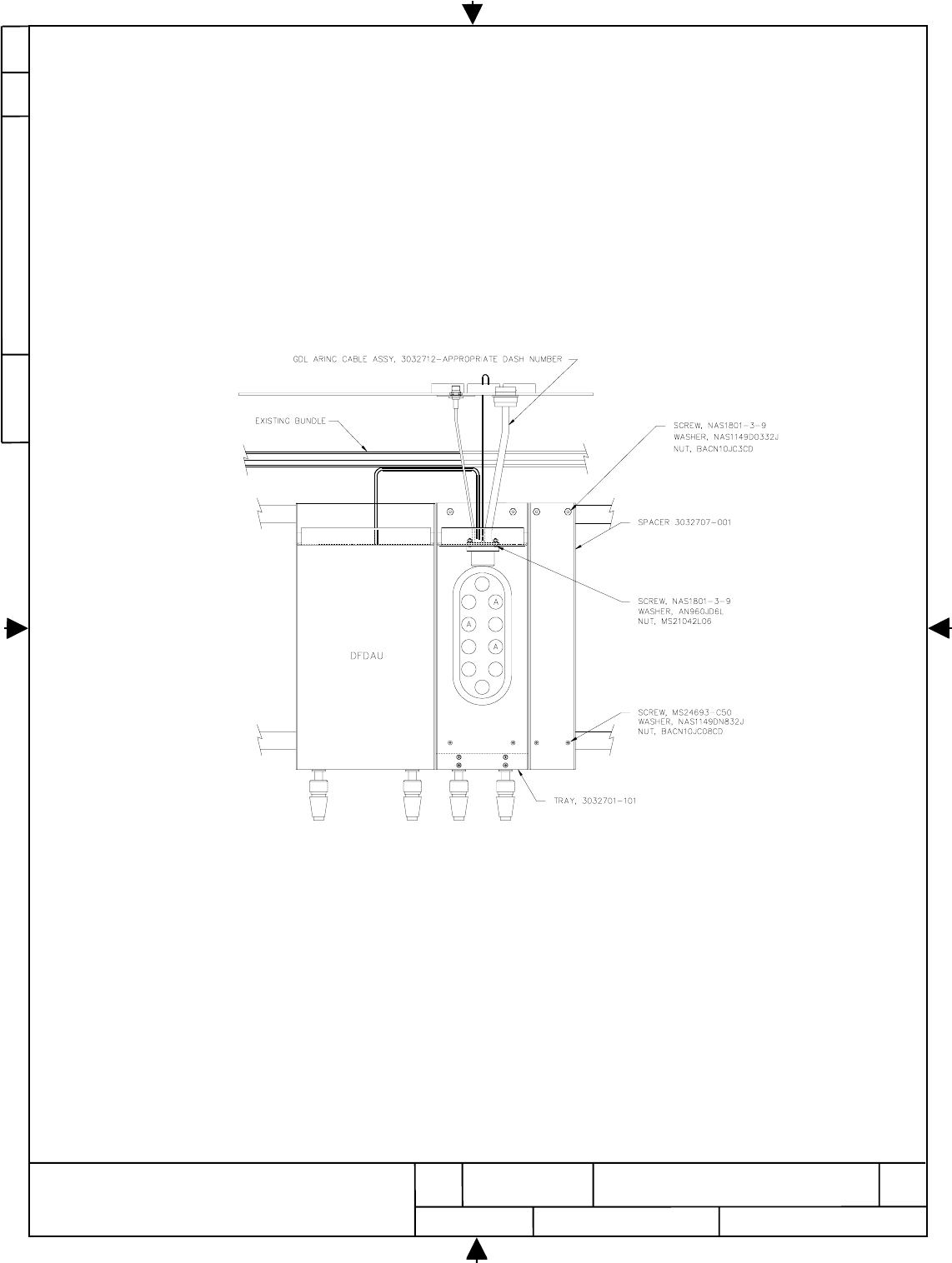
a. Remove existing 6 MCU blank shelf cover plate from the E3-3 shelf on the right side of DFDAU
Tray (M138).
b. Obtain the GDL Tray Assembly P/N 3032701-101 from the GDL Installation Kit.
c. Temporarily install GDL Tray P/N 3032701-101 in the vacant shelf space next to the DFDAU
and also install the spacer plate P/N 3032707-001 next to the GDL Tray
d. Reference Figure 2.1 GDL Tray Assembly and Drawing No. 3032715 E3-3 Shelf Assembly
Installation.
Figure 2.1
GDL Tray Assembly
E
D
O
C
E
G
A
C
ON
G
W
D
H
S
VE
R
7
NONE
7
5
2
4
0
0
7
7004257
77245
HARRIS CORPORATION
GOVERNMENT AEROSPACE SYSTEMS DIVISION
MELBOURNE, FLORIDA 32902
REV
E+
SIZE
A
CAGE CODE DWG NO.
SCALE SHEET
54
27
7
e. Match-drill screw holes for #8 and #10 screws thru the GDL Tray P/N 3032701-101 and the
spacer plate P/N 3032707-001. Deburr the drilled holes.
f. Obtain GDL Connector Assembly 3032712-(appropriate dash no.) from the GDL Installation
Kit. Install connector in GDL Tray using 4 each screws P/N NAS1801-06-6, 4 each washers P/N
AN960JD6L and 4 each nuts P/N MS21042L06 as illustrated in E3-3 Shelf Installation Drawing
3032715. Note: The connector must be pushed against the top of the tray prior to installing the
screws.
g. Insure “Forced Air Cooling” and ventilation integrity by applying a (C/C 188-0329) seal
between GDL Tray P/N 3032701-101, the spacer plate P/N 3032707-001 and the shelf.
h. Install the GDL Tray P/N 3032701-101 and the spacer plate P/N 3032707-001 using screws
MS24693-C50, flat washers NAS1149DN832J and nuts BACN10JC08CD in the forward section
of the shelf and screws NAS1801-3-9, flat washers NAS1149D0332J and nuts BACN10JC3CD
in the back of the shelf per standard Boeing practices. Remove three plugs at locations labeled
“A”.
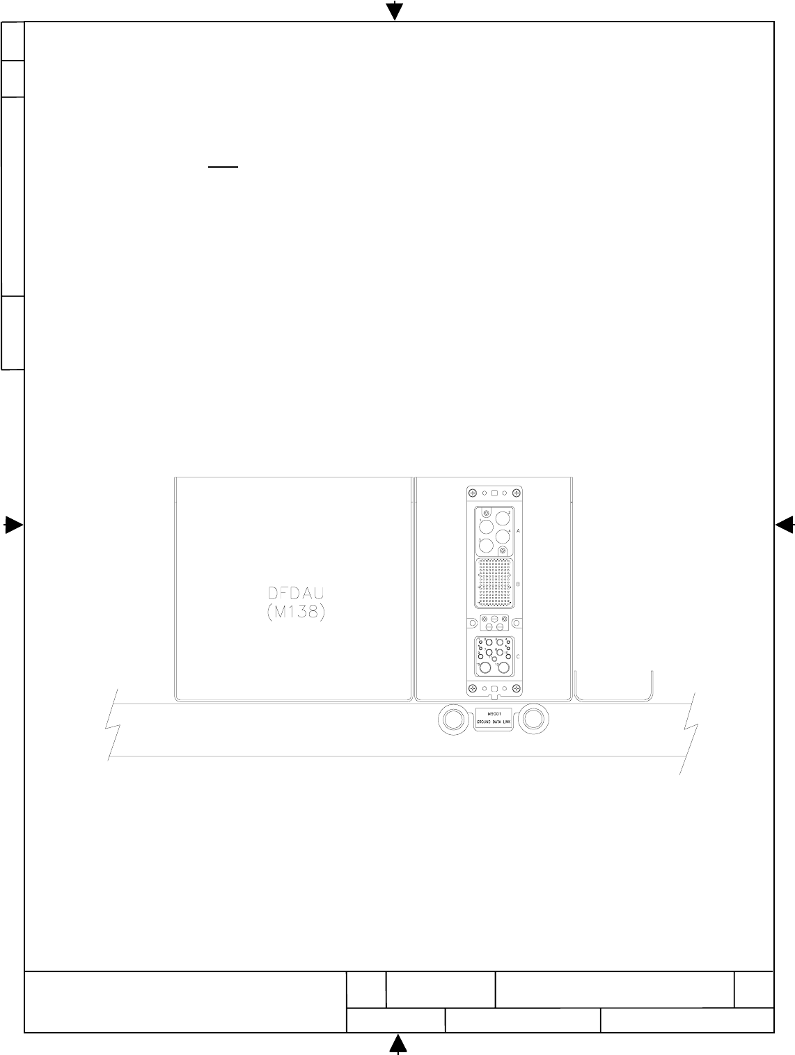
i. Reference Figure 2.2 GDL Tray Assembly - Front View.
Figure 2.2
GDL Tray Assembly - Front View
E
D
O
C
E
G
A
C
ON
G
W
D
H
S
VE
R
8
NONE
7
5
2
4
0
0
7
7004257
77245
HARRIS CORPORATION
GOVERNMENT AEROSPACE SYSTEMS DIVISION
MELBOURNE, FLORIDA 32902
REV
E+
SIZE
A
CAGE CODE DWG NO.
SCALE SHEET
54
27
7
j. Install the following two wires between the GDL ARINC connector J1B to the existing DFDAU
D11A connector as illustrated GDL Wiring Installation Drawing 3032716.
Note: These wires are provided as part of the GDL Connector Assembly 3032712-(appropriate
dash no.) with pins to directly install wires into the existing DFDAU Tray Connector (M138).
1. Connect Wire W9500-003-22W to DFDAU (M138) Connector D11A Pin 9F
2. Connect Wire W9500-004-22W/BLU DFDAU (M138) Connector D11A Pin 9E
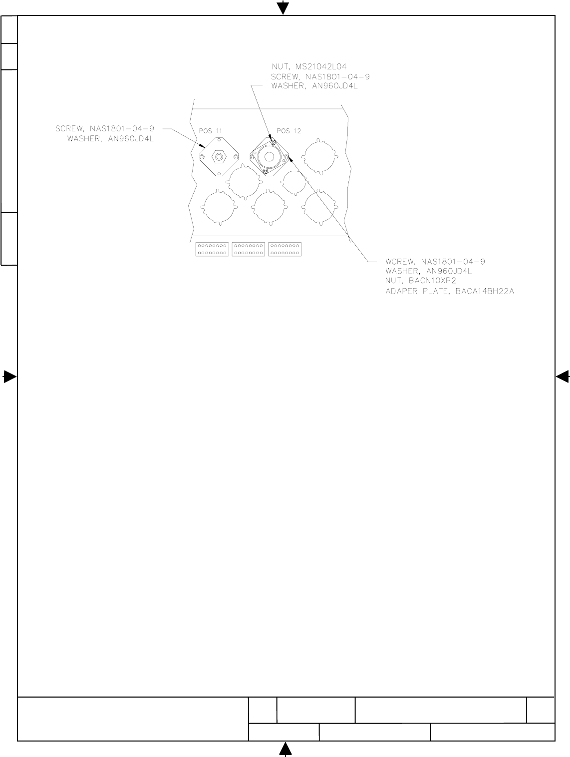
k. Install the D9001J connector from ARINC cable assembly 3032712-(appropriate dash no.) in
position 12 of E3-3 Shelf Disconnect using adapter plate BACA14BH22A, screws NAS1801-04-
9, flat washer AN960JD4L and clip nut BACN10XP2 as illustrated in Figure 2.3 and Drawing
No. 3032715 E3-3 Shelf Assembly Installation.
l. Install the D9000J connector from ARINC Cable Assembly 3032712-(appropriate dash no.) in
position 11 of E3-3 Shelf Disconnect using Screw NAS1801-04-9 and Washer AN960JD4L as
illustrated in Figure 2.3 and Drawing No. 3032715 E3-3 Shelf Assembly Installation.
m. Install the contact on wire W9600-003-20 from ARINC Cable Assembly 3032712-(appropriate
dash no.) in the Terminal Block GDX-1953. Routing and Clamping wire per standard Boeing
practices.
n. Tag E3-3 Shelf as “GDL Modified” and return shelf to aircraft for re-installation in accordance
with Part 3 of this Service Bulletin.
E
D
O
C
E
G
A
C
ON
G
W
D
H
S
VE
R
9
NONE
7
5
2
4
0
0
7
7004257
77245
HARRIS CORPORATION
GOVERNMENT AEROSPACE SYSTEMS DIVISION
MELBOURNE, FLORIDA 32902
REV
E+
SIZE
A
CAGE CODE DWG NO.
SCALE SHEET
54
27
7
Figure 2.3
GDL Tray Assembly - Disconnect
E
D
O
C
E
G
A
C
ON
G
W
D
H
S
VE
R
10
NONE
7
5
2
4
0
0
7
7004257
77245
HARRIS CORPORATION
GOVERNMENT AEROSPACE SYSTEMS DIVISION
MELBOURNE, FLORIDA 32902
REV
E+
SIZE
A
CAGE CODE DWG NO.
SCALE SHEET
54
27
7
4. Re-install E3-3 Shelf
a. Re-install the E3-3 shelf to the aircraft. Ensure proper connection of all connectors and bonding
straps. Perform bonding check per BAC5117. The resistance across any joint shall not exceed
.001 OHMS.
b. Re-install all equipment previously removed to the E3-3 shelf per MM as listed below.
ATC Transponder MM34-53-03
DME MM 34-55-01
Controller - Zone Temperature MM 21-61-00
Controller - Pack Temperature MM 21-51-14
Controller - STBY Pack Temperature MM 21-51-14
DFDAU MM 31-31-03
c. Test all equipment installed on the E3-3 shelf per MM ref. As listed below.
ATC Transponder MM34-53-00
DME MM 34-55-00
Controller - Zone Temperature MM 21-61-00
Controller - Pack Temperature MM 21-51-00
Controller - STBY Pack Temperature MM 21-51-00
DFDAU MM 31-31-00
E
D
O
C
E
G
A
C
ON
G
W
D
H
S
VE
R
11
NONE
7
5
2
4
0
0
7
7004257
77245
HARRIS CORPORATION
GOVERNMENT AEROSPACE SYSTEMS DIVISION
MELBOURNE, FLORIDA 32902
REV
E+
SIZE
A
CAGE CODE DWG NO.
SCALE SHEET
54
27
7
5. Install GDL Circuit Breaker and Placard in Cockpit
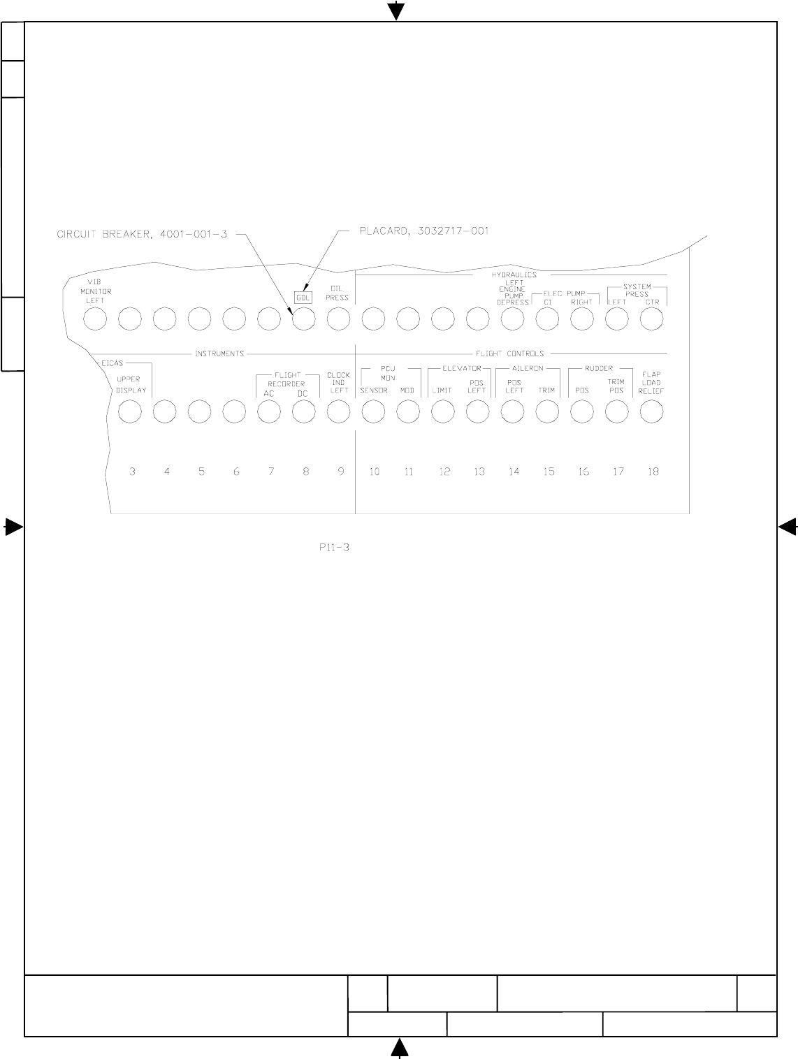
a. Obtain 3A Circuit Breaker P/N 4001-001-3 from GDL Installation Kit.
b. Install circuit breaker in P11-3 Panel Position K8 per standard Boeing Practice..
c. Reference Figure 4.1 GDL Circuit Breaker.
Figure 4.1
GDL Circuit Breaker
E
D
O
C
E
G
A
C
ON
G
W
D
H
S
VE
R
12
NONE
7
5
2
4
0
0
7
7004257
77245
HARRIS CORPORATION
GOVERNMENT AEROSPACE SYSTEMS DIVISION
MELBOURNE, FLORIDA 32902
REV
E+
SIZE
A
CAGE CODE DWG NO.
SCALE SHEET
54
27
7
d. Obtain GDL Circuit Breaker Placard, P/N 3032717-001 from GDL Installation Kit and attach
label on P11-3 panel above installed GDL Circuit Breaker.
e. Obtain wire M22759/11-20-9 from GDL Installation Kit. Label wire using permanent marking
direct on the wire or use pre-printed heat shrinking tubing P/N 3032724-001 from GDL
installation Kit to identify the wire with identification number W0126-9001-20. Install socket
contact P/N BACC47CPIS on wire using Crimp Tool M22520/1-01. Install contact in disconnect
D40610J position 49 as shown in GDL Instruments Wiring Installation Drawing No. 3032716.
f. Route wire W0126-9001-20 from disconnect D40610J to the GDL Circuit Breaker. Clamp, lace
tie along existing wire-runs as required following standard Boeing practices.
g. Install Terminal Lug P/N 1-320551-1 on W0126-9001-20 using Crimp Tool T2210 59824-1 or
equivalent. Connect wire to load side (top) of newly installed 3A GDL Circuit Breaker.
h. Use Boeing jumper wire BACJ40K5A5A6 or obtain wire M22759/11-16-9 from GDL
Installation Kit. Install Terminal Lugs P/N 1-320551 on both ends of wire using Crimp Tool
T2210 59824-1 or equivalent. Connect wire between buss side of newly installed 3A GDL
Circuit Breaker and the buss side of Flight Recorder DC breaker in position J8 of P11-3.
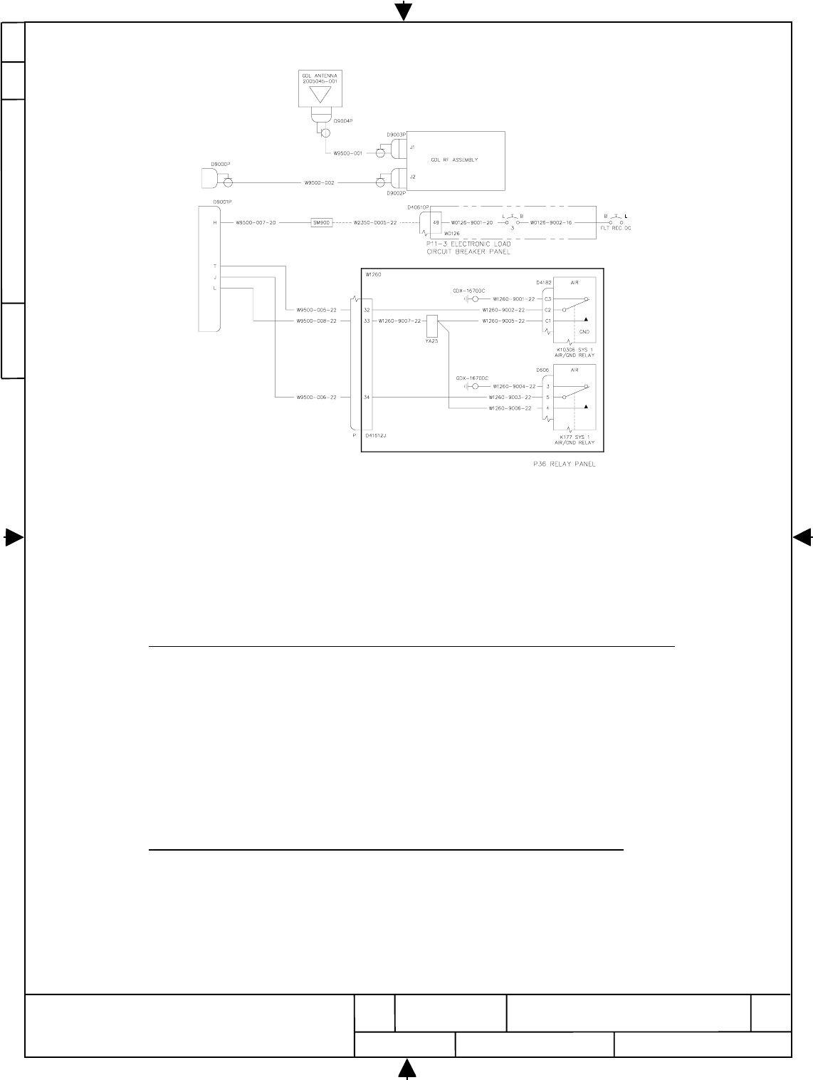
i. Reference GDL Instruments Wiring Installation Drawing No. 3032716.
E
D
O
C
E
G
A
C
ON
G
W
D
H
S
VE
R
13
NONE
7
5
2
4
0
0
7
7004257
77245
HARRIS CORPORATION
GOVERNMENT AEROSPACE SYSTEMS DIVISION
MELBOURNE, FLORIDA 32902
REV
E+
SIZE
A
CAGE CODE DWG NO.
SCALE SHEET
54
27
7
6. Install GDL Wiring in E/E Compartment
a. Gain access to the E/E Compartment E3 Shelf area. Rear shelf access will be required from the
No. 1 Cargo Bay.
b. Obtain three segments of wire M22759/11-22-9 from GDL Installation Kit. The wires are to be
routed from E3-3 shelf Disconnect Position 12 to P36 Relay Panel. Label wire using permanent
marking direct on the wire or use pre-printed heat shrinking tubing P/N 3032724-002, P/N
3032724-003 and P/N 3032724-005 from GDL installation Kit to identify the wire with
identification number W9500-005-22, W9500-006-22 and W9500-008-22 respectively. Install
socket contact P/N M39029/56-351 (part of connector P/N D38999/26WD18SN kit) on one ends
of the wires. Install contact BACC47CN1 on the other ends of the wires. Refer to the attached
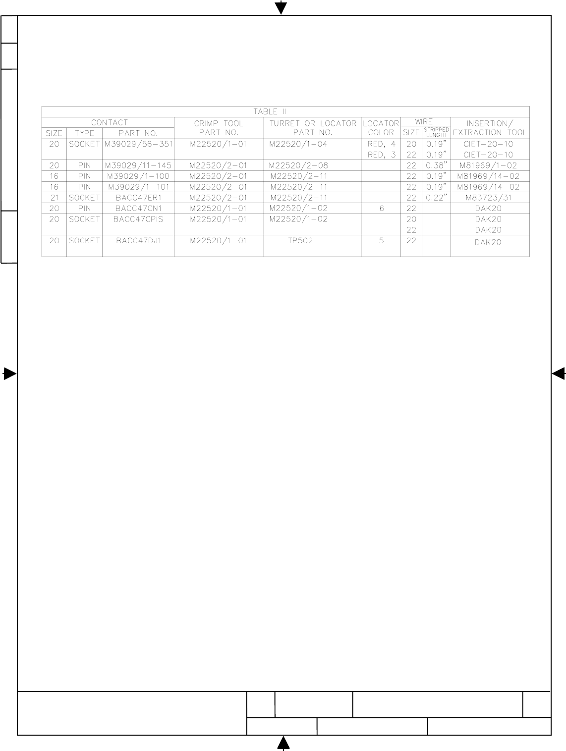
Table 5.1 for tooling information.
c. Locate E3-1 Shelf Disconnect D40676P and wire W2350-0005-22 connected to Pin 1. Note:
This is a spare wire which is routed to the P11 Circuit Breaker Panel.
d. Extract W2350-0005-22 from D40676P connector and cut off contact. Obtain wire M22759/11-
20-9 from GDL Installation Kit. The wires are to be routed from E3-3 shelf Disconnect Position
12 to D40676P position. Label wire using permanent marking direct on the wire or use pre-
printed heat shrinking tubing P/N 3032724-004 from GDL installation Kit to identify the wire
with identification number W9500-007-20. Install socket contact P/N M39029/56-351 on one
end of wire. Refer to the attached Table 5.1 for tooling information.
e. Splice other end of wire W9500-007-20 to W2350-0005-22 using solder splice D-110-41 from
GDL Installation Kit. Clamp, lace and tie as required following standard Boeing practices.
f. Obtain the connector D9001P (P/N D38999/26WD18SN) and Backshell P/N M85049/38S15W
from the GDL Installation Kit. Insert the contacts M39029/56-351 (part of connector P/N
D38999/26WD18SN kit) into D9001P as follows:
W9500-005-22 to D9001P Pin T
W9500-006-22 to D9001P Pin J
W9500-008-22 to D9001P Pin L
W9500-007-20 to D9001P Pin H
Install the backshell P/N M85049/38S15W to D9001P and install the connector to D9001J
which is located at position 12 of E3-3 Shelf Disconnect.
g. Route the remaining three wires (W9500-005-22, W9500-006-22 and W9500-008-22 ) to the
P36 Relay Panel area. Clamp, lace and tie along existing wire-runs as required following
standard practices.
h. Obtain access to the P36 Panel Disconnect D41612P. Using standard insertion/extraction tool,
insert the contacts BACC47CN1 into D41612P as follows:
W9500-005-22 to D41612P Pin 32
W9500-006-22 to D41612P Pin 34
W9500-008-22 to D41612P Pin 33
E
D
O
C
E
G
A
C
ON
G
W
D
H
S
VE
R
14
NONE
7
5
2
4
0
0
7
7004257
77245
HARRIS CORPORATION
GOVERNMENT AEROSPACE SYSTEMS DIVISION
MELBOURNE, FLORIDA 32902
REV
E+
SIZE
A
CAGE CODE DWG NO.
SCALE SHEET
54
27
7
Figure 5.1
GDL E/E Compartment Wiring
i. Obtain wire M22759/11-22, contact BACC47CP1S and BACC47DJ1. Using Crimping Tool
and Turret as listed in Table 5.1 to terminate the following AIR/GND wire within the P36
Relay Panel:
From Wire To______
D41612J Pin 32 W1260-9002-22 K10306 D4182 Pin C2
(Contact BACC47CPIS) (M22759/11-22-9) (Contact BACC47DJI)
Label wire using permanent marking direct on the wire or use pre-printed heat shrinking tubing
P/N 3032724-007 from GDL installation Kit to identify the wire with identification number
W1260-9002-22.
j. Obtain wire M22759/11-22, contact BACC47CP1S and BACC47ER1. Using Crimping Tool
and Turret as listed in Table 5.1 to terminate the following AIR/GND wire within the P36
Relay Panel:
From Wire To______
D41612J Pin 34 W1260-9003-22 K177 D606 Pin 5
(Contact BACC47CPIS) (M22759/11-22-9) (Contact BACC47ERI)
Label wire using permanent marking direct on the wire or use pre-printed heat shrinking tubing
P/N 3032724-008 from GDL installation Kit to identify the wire with identification number
W1260-9003-22.
E
D
O
C
E
G
A
C
ON
G
W
D
H
S
VE
R
15
NONE
7
5
2
4
0
0
7
7004257
77245
HARRIS CORPORATION
GOVERNMENT AEROSPACE SYSTEMS DIVISION
MELBOURNE, FLORIDA 32902
REV
E+
SIZE
A
CAGE CODE DWG NO.
SCALE SHEET
54
27
7
k. Obtain wire M22759/11-22, contact BACC47DE7 and BACC47DJ1. Using Crimping Tool and
Turret as listed in Table 5.1 to terminate the following GROUND wire within the P36 Relay
Panel:
From Wire To______
GDX-1670DC W1260-9001-22 K10306 D4182 Pin C3
(Contact BACC47DE7) (M22759/11-22-9) (Contact BACC47DJI)
Label wire using permanent marking direct on the wire or use pre-printed heat shrinking tubing
P/N 3032724-006 from GDL installation Kit to identify the wire with identification number
W1260-9001-22.
l. Obtain wire M22759/11-22, contact BACC47DE7 and BACC47ER1. Using Crimping Tool and
Turret as listed in Table 5.1 to terminate the following GROUND wire within the P36 Relay
Panel:
From Wire To______
GDX-1670DC W1260-9004-22 K177 D606 Pin 3
(Contact BACC47DE7) (M22759/11-22-9) (Contact BACC47ERI)
Label wire using permanent marking direct on the wire or use pre-printed heat shrinking tubing
P/N 3032724-009 from GDL installation Kit to identify the wire with identification number
W1260-9004-22.
m. Obtain wire M22759/11-22, contact BACC47CP1S, M39029/11-145, BACC47DJ1 and
BACC47ER1. Using Crimping Tool and Turret as listed in Table 5.1 to terminate the following
3 28VDC Discrete wires within the P36 Relay Panel:
From Wire To______
YA25 W1260-9005-22 K10306 D4182 Pin C1
(Contact M39029/11-145) (M22759/11-22-9) (Contact BACC47DJI)
YA25 W1260-9006-22 K177 D606 Pin 4
(Contact M39029/11-145) (M22759/11-22-9) (Contact BACC47ERI)
YA25 W1260-9007-22 D41612J Pin 33
(Contact M39029/11-145) (M22759/11-22-9) (Contact BACC47CPIS)
n. Label wires using permanent marking direct on the wires or use pre-printed heat shrinking
tubing P/N 3032724-010, P/N 3032724-011 and P/N 3032724-012 from GDL installation Kit to
identify the wires with identification number W1260-9005-22, W1260-9006-22 and W1260-
9007-22 respectively.
E
D
O
C
E
G
A
C
ON
G
W
D
H
S
VE
R
16
NONE
7
5
2
4
0
0
7
7004257
77245
HARRIS CORPORATION
GOVERNMENT AEROSPACE SYSTEMS DIVISION
MELBOURNE, FLORIDA 32902
REV
E+
SIZE
A
CAGE CODE DWG NO.
SCALE SHEET
54
27
7
Table 5.1 Tooling Information
E
D
O
C
E
G
A
C
ON
G
W
D
H
S
VE
R
17
NONE
7
5
2
4
0
0
7
7004257
77245
HARRIS CORPORATION
GOVERNMENT AEROSPACE SYSTEMS DIVISION
MELBOURNE, FLORIDA 32902
REV
E+
SIZE
A
CAGE CODE DWG NO.
SCALE SHEET
54
27
7
E
D
O
C
E
G
A
C
ON
G
W
D
H
S
VE
R
18
NONE
7
5
2
4
0
0
7
7004257
77245
HARRIS CORPORATION
GOVERNMENT AEROSPACE SYSTEMS DIVISION
MELBOURNE, FLORIDA 32902
REV
E+
SIZE
A
CAGE CODE DWG NO.
SCALE SHEET
54
27
7
7. Install Coaxial Cable Between E/E Compartment and RF Assembly
a. Obtain GDL RF Cable P/N 3032710-101 from the GDL Installation Kit. Note: The end with the
pre-installed connector labeled D9000P will be connected to the E3-3 Shelf Disconnect. The un-
terminated end will be routed up to the ceiling area in the passenger cabin and connects to the
GDL RF Assembly which will be installed in the overhead area at STA 470 between stringers S-
2R and S-3R.
E
D
O
C
E
G
A
C
ON
G
W
D
H
S
VE
R
19
NONE
7
5
2
4
0
0
7
7004257
77245
HARRIS CORPORATION
GOVERNMENT AEROSPACE SYSTEMS DIVISION
MELBOURNE, FLORIDA 32902
REV
E+
SIZE
A
CAGE CODE DWG NO.
SCALE SHEET
54
27
7
E
D
O
C
E
G
A
C
ON
G
W
D
H
S
VE
R
20
NONE
7
5
2
4
0
0
7
7004257
77245
HARRIS CORPORATION
GOVERNMENT AEROSPACE SYSTEMS DIVISION
MELBOURNE, FLORIDA 32902
REV
E+
SIZE
A
CAGE CODE DWG NO.
SCALE SHEET
54
27
7
GDL RF Cable
Figure 6.1
b. Connect D9000P to the Disconnect D9000J located at E3-3 Shelf Disconnect position 12.
c. Route the GDL RF Cable W9500-002 (P/N 3032710-101) from the E3-3 Shelf Disconnect area
to the GDL RF Assembly. The cable will be routed with existing cable run W2617 up to the
passenger cabin area along the forward side of STA 500 frame.
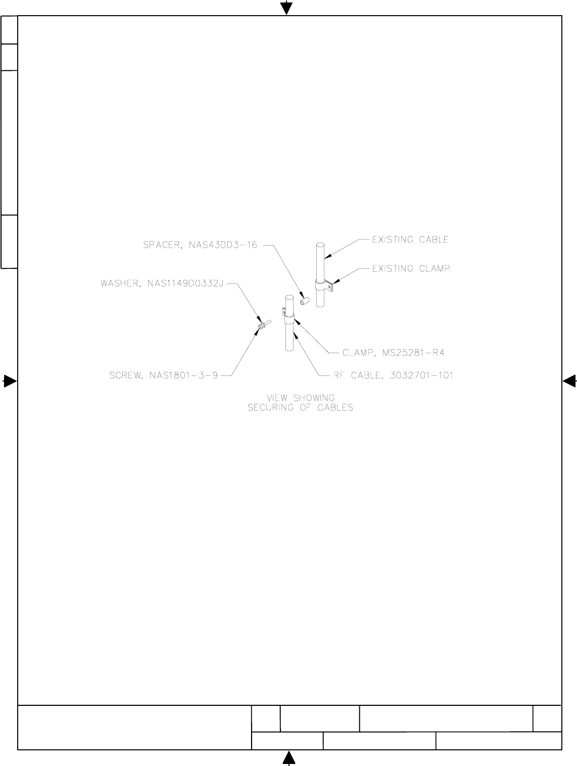
d. “Butterfly Clamp” GDL RF Cable W9500-002 (P/N 3032710-101) to the existing cable run as
shown in Figure 4.2 using spacer NAS43DD3-16, cable clamp MS25281-R4 ,screw NAS1801-3-
8 and washer NAS1149D0332J.
Figure 6.2
GDL RF Cable Installation
e. Complete routing of GDL RF cable from E3-3 shelf area to GDL RF Assembly at STA 470
between stringers S-2R and S-3R and temporarily retain at that location. Clamp, lace and tie as
required following standard Boeing practices.
E
D
O
C
E
G
A
C
ON
G
W
D
H
S
VE
R
21
NONE
7
5
2
4
0
0
7
7004257
77245
HARRIS CORPORATION
GOVERNMENT AEROSPACE SYSTEMS DIVISION
MELBOURNE, FLORIDA 32902
REV
E+
SIZE
A
CAGE CODE DWG NO.
SCALE SHEET
54
27
7
8. Install GDL Antenna Doubler Plate and GDL Antenna
a.
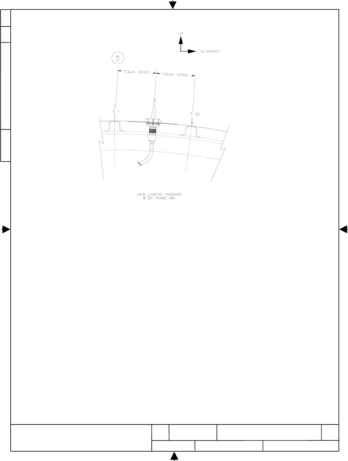
Remove insulation between STA 460 and STA 480, also between Stringers S-1 and S-2R per
standard Boeing practices.
b. Obtain the GDL Doubler Plate P/N 3032722-001 from the GDL Installation Kit.
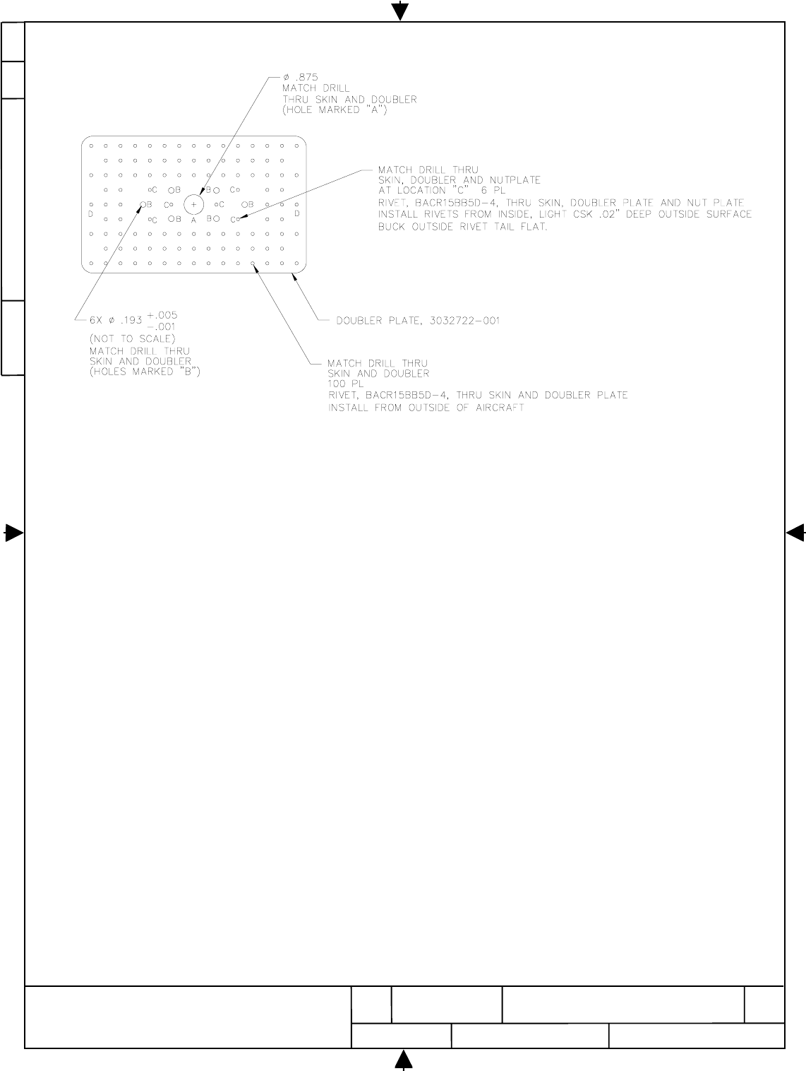
C. Locate center pilot hole labeled “a” at Doubler plate to the STA 470 midway between stringers
S-1 and S-2R. Locate most forward and most aft rivet holes labeled “d” at doubler plate.
D. Drill the three pilot holes .098” diameter (#40 drill) through aircraft skin and Cleco doubler plate
3032722-001 in place.
E. Use Doubler Plate P/N 3032722-001 as a template to locate and drill remaining pilot holes .098”
diameter (#40 drill) through aircraft skin.
F. Redrill outer aircraft skin on 98 unlabelled pilot holes, 2 labeled “d” and 6 labeled “c” pilot
holes for BACR15BB5D rivets I.A.W. B757 SRM Sec. 51-40-08, Fig. 2, Detail II.
G. Redrill 6 of the pilot holes labeled “b” to ∅.193 (#10 drill) for screw clearance.
H. Redrill center pilot holes to ∅.875 (7/8 drill) for antenna connector clearance.
I. Deburr all drilled holes prior to installation of Doubler Plate P/N 3032722-001 to aircraft skin.
J. Apply sealant P/N PR870 B1/2-semkit to the contact surface of Doubler Plate P/N 3032722-001
and rivets BACR15BB5D-4 (prior to installation) per Standard Boeing practices.
K. Install Doubler Plate P/N 3032722-001 in place using rivets BACR15BB5D per Standard Boeing
practices. Do not install rivets BACR15BB5D-4 into the location labeled “c”.
L. Apply sealant P/N PR870 B1/2-semkit to the contact surface of nut plate P/N 3032720-101 and
rivets BACR15BB5D-4 (prior to installation) per Standard Boeing practices.
M. Install nut plate P/N3032720-101 in place using rivets BACR15BB5D-4 through Doubler Plate
P/N 3032722-001 and aircraft skin from inside of the aircraft and light CSK .020”deep outside
surface. Buck outside rivet tail flat per Standard Boeing practices. Note: Avoid getting sealant
inside of self locking nuts.
N. Clean surface of aircraft, doubler plate and nut plate. Apply approved Corrosion inhibitor to
inside surface of aircraft skin, doubler plate and nut plate per Standard Boeing practices.
o. Refer to Figure 7.1 and GDL antenna installation - US Airways, B757-200 Drawing No.
3032703.
E
D
O
C
E
G
A
C
ON
G
W
D
H
S
VE
R
22
NONE
7
5
2
4
0
0
7
7004257
77245
HARRIS CORPORATION
GOVERNMENT AEROSPACE SYSTEMS DIVISION
MELBOURNE, FLORIDA 32902
REV
E+
SIZE
A
CAGE CODE DWG NO.
SCALE SHEET
54
27
7
Figure 7.1 GDL Doubler Plate Installation
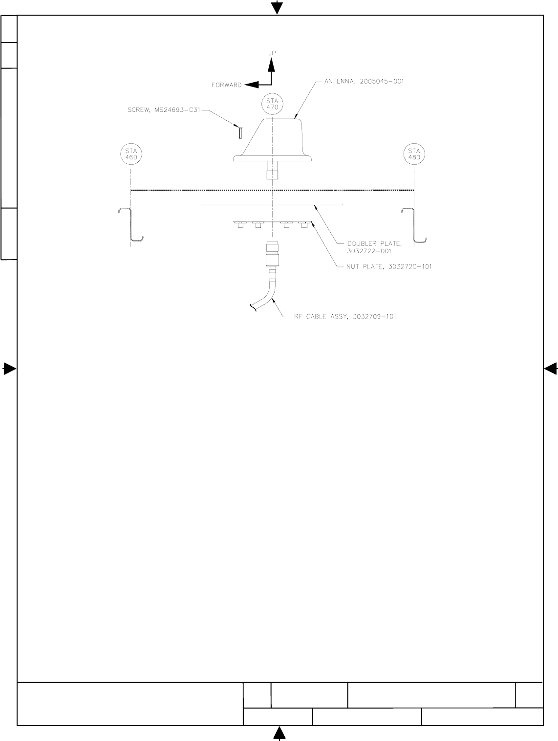
p. Obtain antenna P/N 2005045-001 and screws P/N MS24693-C30 from GDL Installation Kit
q. Remove tape holding gasket prior to installing antenna. Clean GDL Antenna P/N 2005045-001
base and mating aircraft fuselage skin areas with approved solvent per standard Boeing
practices.
r. Apply sealant PR870 B1/2-SEMKIT to the thread of screws P/N MS24693-C30 prior to
installation.
s. Ensure the gasket is retained on antenna prior to installing antenna. Place GDL Antenna P/N
2005045-001 in position and secure using the six MS24693-C30 screws. Fillet seal around the
GDL Antenna P/N 2005045-001 base and aircraft skin using sealant P/N PR870 B1/2-SEMKIT.
Remove excess adhesive.
t. Obtain the RF cable assembly P/N3032709-101 from GDL Installation Kit.
u. Install the connector labeled D9004P to S-Band Antenna’s connector.
v. Reinstall the insulation per standard Boeing Practice and Route the RF cable to the location
between STA 440 and STA 460, also between Stringer S-2R and S-3R below the insulation
material. Clamp, lace tie the cable to the existing wire bundle per standard Boeing practice.
E
D
O
C
E
G
A
C
ON
G
W
D
H
S
VE
R
23
NONE
7
5
2
4
0
0
7
7004257
77245
HARRIS CORPORATION
GOVERNMENT AEROSPACE SYSTEMS DIVISION
MELBOURNE, FLORIDA 32902
REV
E+
SIZE
A
CAGE CODE DWG NO.
SCALE SHEET
54
27
7
GDL Antenna Installation
Figure 7.2
E
D
O
C
E
G
A
C
ON
G
W
D
H
S
VE
R
24
NONE
7
5
2
4
0
0
7
7004257
77245
HARRIS CORPORATION
GOVERNMENT AEROSPACE SYSTEMS DIVISION
MELBOURNE, FLORIDA 32902
REV
E+
SIZE
A
CAGE CODE DWG NO.
SCALE SHEET
54
27
7
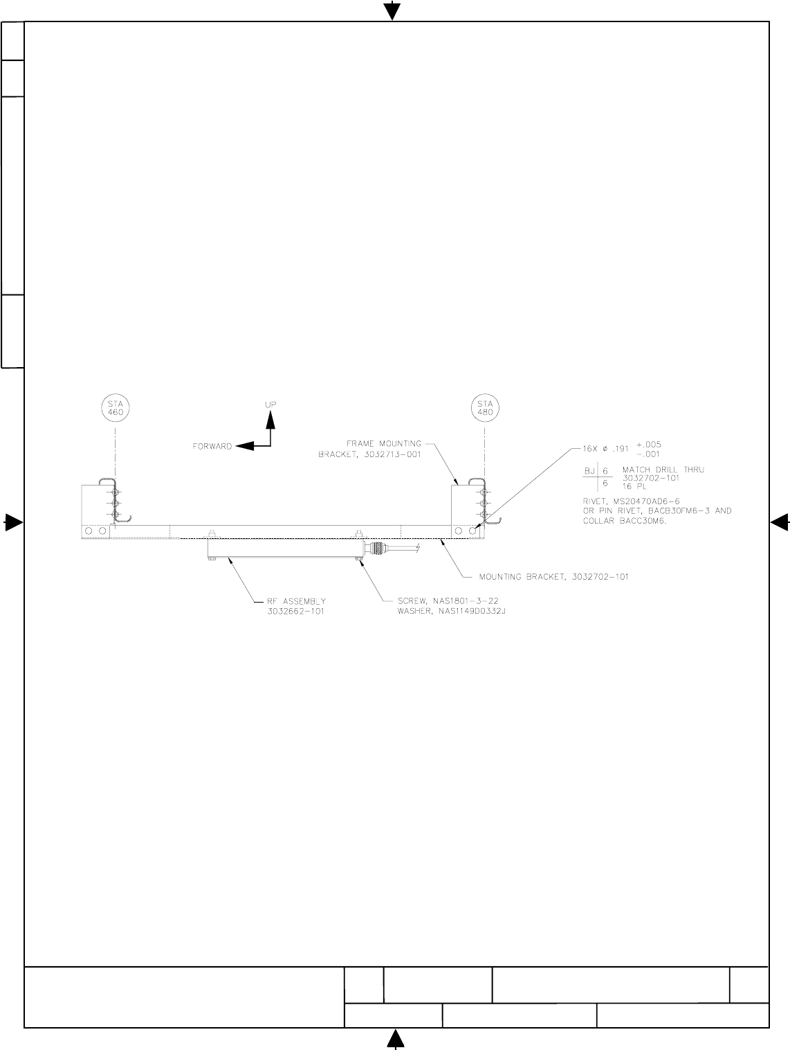
w. Temporary secure the RF cable for the later installation to RF assembly PN 3032662-101.
STA 470 GDL Antenna Installation
Figure 7.3
E
D
O
C
E
G
A
C
ON
G
W
D
H
S
VE
R
25
NONE
7
5
2
4
0
0
7
7004257
77245
HARRIS CORPORATION
GOVERNMENT AEROSPACE SYSTEMS DIVISION
MELBOURNE, FLORIDA 32902
REV
E+
SIZE
A
CAGE CODE DWG NO.
SCALE SHEET
54
27
7
9. Install GDL RF Assembly
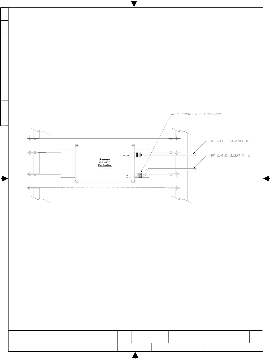
a. Perform installation of the RF assembly, P/N. 3032662-101 to aircraft frames using Drawing
No. 3032714, GDL RF Assembly Installation - US Airways, B757-200 and this procedure.
b. Gain access to and remove insulation covering the frames at STA 460 and STA 480 per B757-
200 Maintenance Manual.
c. Refer to Figure 8.1. Using the Mounting Bracket P/N 3032702-101 and the four Frame
Mounting Brackets P/N 3032713-001 as templates, match-drill the 12 rivet holes required for
rivets MS20470AD6-6 on the frames at STA 460 and STA 480.
RF Assembly Mounting Bracket Installation
Figure 8.1
d. Match drill the 16 rivet holes required for rivets MS20470AD6-6 or equivalent pin rivet
BACB30FM6 on the Mounting Bracket P/N 3032702-101 using the Frame Mounting Bracket
P/N 3032713-001 as a template.
e.
Deburr all drilled holes prior to installation of rivets.
E
D
O
C
E
G
A
C
ON
G
W
D
H
S
VE
R
26
NONE
7
5
2
4
0
0
7
7004257
77245
HARRIS CORPORATION
GOVERNMENT AEROSPACE SYSTEMS DIVISION
MELBOURNE, FLORIDA 32902
REV
E+
SIZE
A
CAGE CODE DWG NO.
SCALE SHEET
54
27
7
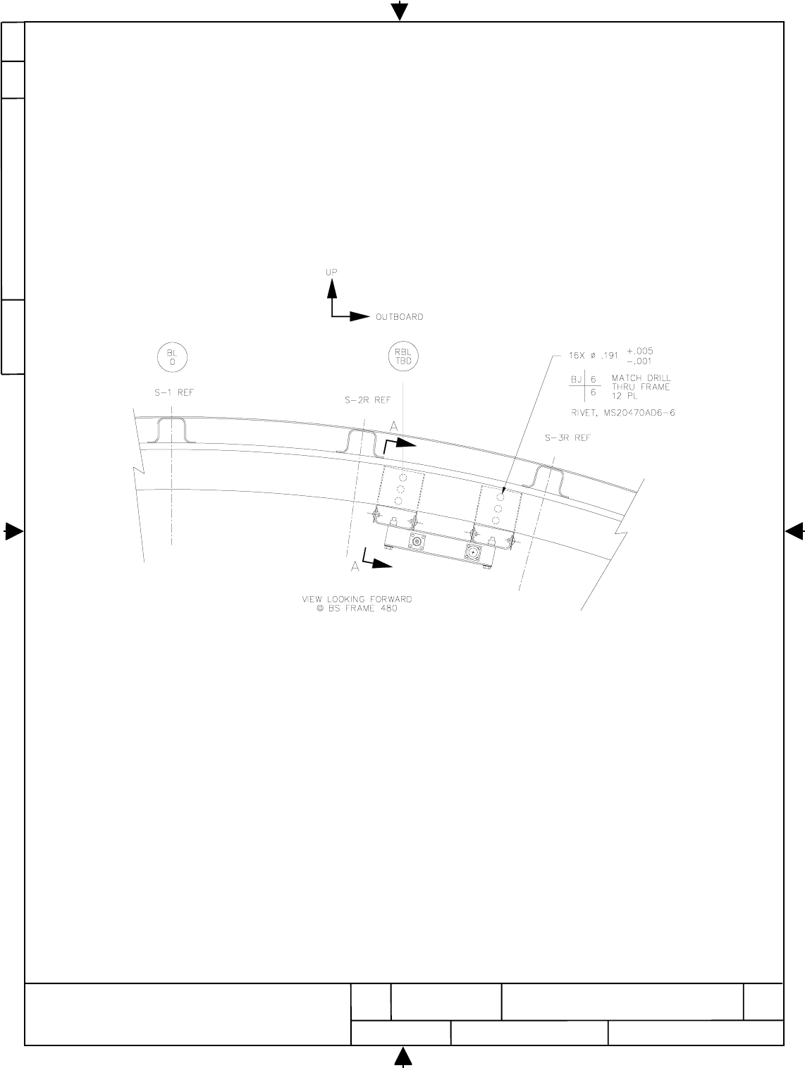
f. Install 12 rivets MS20470AD6-6 connecting the Frame Mounting Bracket P/N 3032713-001 to
the frames at STA 460 and STA 480 per US Airways Maintenance Manual procedures.
g. Re-install the frame insulation per B757-200 maintenance manual ensuring the lower ends of
the Frame Mounting brackets P/N 3032713-001 protrude through the insulation.
h. Install rivets MS20470AD6-6 or equivalent pin rivet BACB30FM6-3 and collar BACC30M6
connecting the Mounting Bracket P/N 3032702-101 to the Frame Mounting Bracket P/N
3032713-001 per standard Boeing procedures.
i. Install the RF Assembly P/N 3032662-101 to the Mounting Bracket P/N 3032702-101 using the
four hex head screws NAS1801-3-22 and the four flat washers NAS1149D0332J.
GDL RF Assembly Installation
Figure 8.2
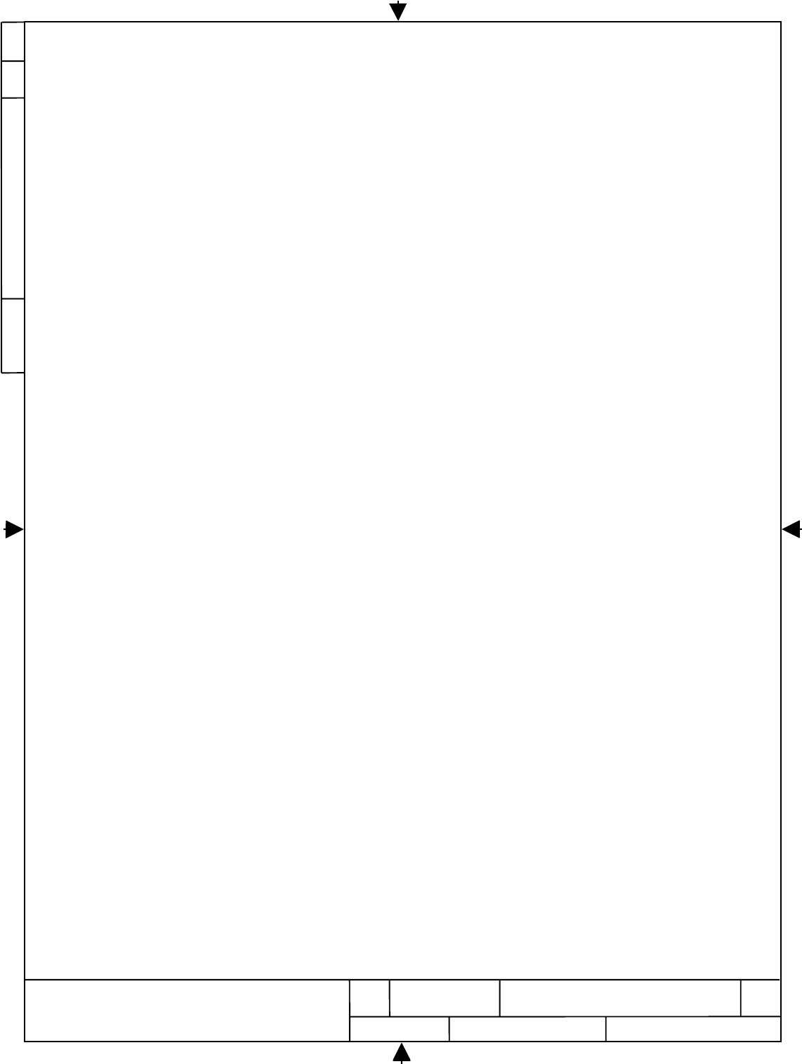
j. Install the connector D9003P of RF cable W9500-001 (P/N 3032709-101) previously installed to
S-band antenna to J1 Antenna connector of RF assembly P/N 3032662-101.
k. Obtain RF cable W9500-002 (P/N 3032710-101) previously routed from E3-3 Shelf Disconnect.
l. Obtain RF Connector P/N 1599-5025 from GDL Installation Kit
E
D
O
C
E
G
A
C
ON
G
W
D
H
S
VE
R
27
NONE
7
5
2
4
0
0
7
7004257
77245
HARRIS CORPORATION
GOVERNMENT AEROSPACE SYSTEMS DIVISION
MELBOURNE, FLORIDA 32902
REV
E+
SIZE
A
CAGE CODE DWG NO.
SCALE SHEET
54
27
7
m. Cut RF Cable W9500-002 (P/N 3032710-101) to length required to terminate cable to GDL RF
Assembly P/N 3032662-101 connector J2. Note: A small service loop of approximately 18”
should be included prior to cutting GDL RF Cable.
n. Terminate RF Cable W9500-002 (P/N 3032710-101) with M/ACOM RF Connector P/N 1599-
5025 using M/ACOM spreading tool T-15073-P4, spacer tool T-15075 and standard .324 hex
crimp die. Install connector in accordance with instructions outlined in M/ACOM Drawing
1599-5025 sheet 3 of 3 attached to this Service Bulletin
o. Connect the terminated connector to RF assembly P/N 3032662-101 connector labeled “ J2
INPUT”.
GDL RF Assembly Installation
Figure 8.3
E
D
O
C
E
G
A
C
ON
G
W
D
H
S
VE
R
28
NONE
7
5
2
4
0
0
7
7004257
77245
HARRIS CORPORATION
GOVERNMENT AEROSPACE SYSTEMS DIVISION
MELBOURNE, FLORIDA 32902
REV
E+
SIZE
A
CAGE CODE DWG NO.
SCALE SHEET
54
27
7
10. Install GDL Airborne Unit in GDL Tray
a. Obtain GDL airborne unit P/N 3026585-102. from GDL installation kit
b. Verify 28VDC at GDL tray ARINC connector pin C-1
.
c. Install the GDL airborne unit into the E3-3 shelf GDL tray per standard Boeing practices.
E
D
O
C
E
G
A
C
ON
G
W
D
H
S
VE
R
29
NONE
7
5
2
4
0
0
7
7004257
77245
HARRIS CORPORATION
GOVERNMENT AEROSPACE SYSTEMS DIVISION
MELBOURNE, FLORIDA 32902
REV
E+
SIZE
A
CAGE CODE DWG NO.
SCALE SHEET
54
27
7
11. Perform GDL System Checkout
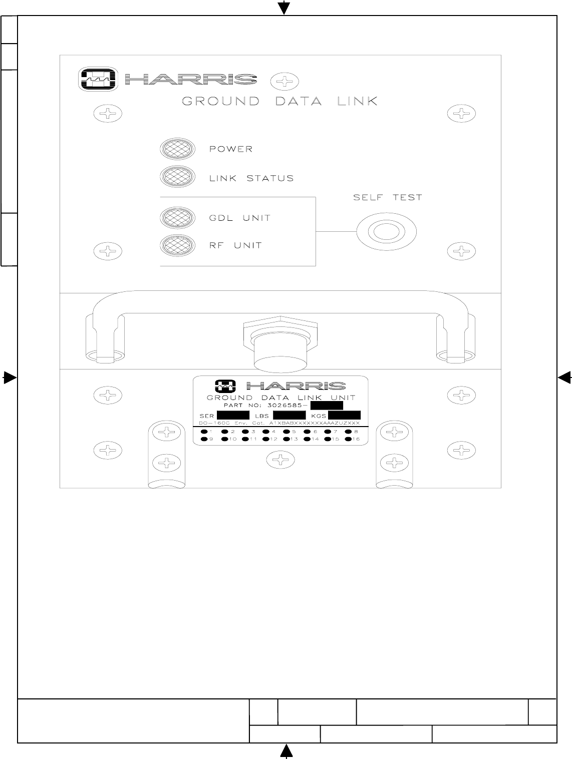
a. GDL UNIT ACTIVATION
1. Activate GDL Circuit Breaker and observe the following on the front panel of GDL Unit
located in E/E Compartment.
2. Verify green LED labeled “POWER” is illuminated.
3. Verify front panel green LED labeled “GDL UNIT” is illuminated within 60 seconds of
applying 28VDC power.
4. Verify that the front panel green LED labeled “LINK STATUS” blinks on and off
several times and continues to randomly blink a few times per minute.
b. GDL SELF TEST PROCEDURE
1. Press and release the “SELF TEST” on front panel.
2. Verify front panel green LED labeled “GDL UNIT” illuminates within 60 sec after the
“SELF TEST” button was pushed.
3. Verify front panel green LED labeled “RF UNIT” illuminates. Note that this step can
take several minutes and is dependent on the size of the flight file which was recorded
during the previous flight.
4. Verify “LINK STATUS” LED start to blinks “On and Off” several times. Also verify
that “GDL UNIT” and “RF UNIT” LEDs extinguish after several minutes.
5. Verify front panel green LED labeled “RF UNIT” illuminates almost at the same time as
the “GDL UNIT” LED.
E
D
O
C
E
G
A
C
ON
G
W
D
H
S
VE
R
30
NONE
7
5
2
4
0
0
7
7004257
77245
HARRIS CORPORATION
GOVERNMENT AEROSPACE SYSTEMS DIVISION
MELBOURNE, FLORIDA 32902
REV
E+
SIZE
A
CAGE CODE DWG NO.
SCALE SHEET
54
27
7
GDL Airborne Unit
Figure 10.1
E
D
O
C
E
G
A
C
ON
G
W
D
H
S
VE
R
31
NONE
7
5
2
4
0
0
7
7004257
77245
HARRIS CORPORATION
GOVERNMENT AEROSPACE SYSTEMS DIVISION
MELBOURNE, FLORIDA 32902
REV
E+
SIZE
A
CAGE CODE DWG NO.
SCALE SHEET
54
27
7
12. GDL Installation Kit List
QTY PART NUMBER SOURCE CLASS/CONTROL DESCRIPTION
41-320551-1 AMP Lug
11599-5025 M/A com Connector, RF
12005045-001 Harris Antenna, S Band
13026585-102 Harris GDL airborne Unit
13032662-101 Harris RF Assembly
13032701-101 Harris Tray
13032702-101 Harris Bracket, Mnt - RF Assy
13032707-001 Harris Plate, Spacer
13032709-101 Harris Cable Assy, RF/Antenna
13032710-101 Harris Cable Assy - GDL/RF
13032712-appropriate
dash no. Harris Cable Assy, ARINC Connector
43032713-001 Harris Bracket, Mtg, Frame
13032717-001 Harris Placard
13032720-101 Harris Plate, Nut
13032722-001 Harris Plate, Doubler - Antenna
33032724-001 Harris Marker, wire
33032724-002 Harris Marker, wire
33032724-003 Harris Marker, wire
33032724-004 Harris Marker, wire
33032724-005 Harris Marker, wire
33032724-006 Harris Marker, wire
33032724-007 Harris Marker, wire
33032724-008 Harris Marker, wire
33032724-009 Harris Marker, wire
33032724-010 Harris Marker, wire
33032724-011 Harris Marker, wire
33032724-012 Harris Marker, wire
14001-001-3 Air Technics Circuit Breaker
4AN960JD4L Various Washer
8AN960JD6L Various Washer
3BACC47CN1 Various Contact
4BACC47CP1S Various Contact
3BACC47ER1 Various Contact
16 BACC30M6 Various Collar
16 BACB30FM6-3 Various Pin Rivet
1BACA14BH22A Various Adapter plate assembly
3BACC47DJ1 Various Contact
4BACN10JC08CD Various Nut
8BACN10JC3CD Various Nut
2BACN10XP2 Various Nut, Clip
106 BACR15BB5D-4 Various Rivet
E
D
O
C
E
G
A
C
ON
G
W
D
H
S
VE
R
32
NONE
7
5
2
4
0
0
7
7004257
77245
HARRIS CORPORATION
GOVERNMENT AEROSPACE SYSTEMS DIVISION
MELBOURNE, FLORIDA 32902
REV
E+
SIZE
A
CAGE CODE DWG NO.
SCALE SHEET
54
27
7
1D-110-41 Raychem Solder Sleeving
1D38999/26WD18SN Various Connector
A/R M22759/11-16-9 Various Wire
A/R M22759/11-20-9 Various Wire
A/R M22759/11-22-9 Various Wire
2BACC47DE7 Various Contact
1M39029/1-101 Various Contact
3M39029/11-145 Various Contact
4M39029/56-351 Various Contact
1M85049/38S15W Various Backshell
28 MS20470AD6-6 Various Rivet
2MS21042L04 Various Nut
8MS21042L06 Various Nut
4MS24693-273 Various Screw
6MS24693-C31 Various Screw
4MS24693-C50 Various Screw
24 MS25281-R4 Various Clamp, Cable
36 NAS1149D0332J Various Washer
4NAS1149DN832J Various Washer
4NAS1801-04-9 Various Screw
8NAS1801-06-6 Various Screw
4NAS1801-3-22 Various Screw
27 NAS1801-3-9 Various Screw
24 NAS43DD3-16 Various Spacer
A/R PR870B1/2-SEMKIT Courtaulds Sealing compound
E
D
O
C
E
G
A
C
ON
G
W
D
H
S
VE
R
33
NONE
7
5
2
4
0
0
7
7004257
77245
HARRIS CORPORATION
GOVERNMENT AEROSPACE SYSTEMS DIVISION
MELBOURNE, FLORIDA 32902
REV
E+
SIZE
A
CAGE CODE DWG NO.
SCALE SHEET
54
27
7
13. Drawing List
Drawing Number Title
3032703 GDL Antenna Installation - US Airways, B757-200
3032715 E3-3 Shelf Assembly Installation - US Airways, B757-200
3032714 GDL RF Assembly Installation - US Airways, B757-200
3032726 GDL Circuit Breaker Installation - US Airways, B757-200
3032716 GDL Instruments Wiring Installation - US Airways, B757-200
1599-5025 (SH3) M/A-COM Connector Termination Instruction Sheet