GE Healthcare MINITEL2010 Mini Telemetry System Tx User Manual

GE Healthcare Mini Telemetry System Tx
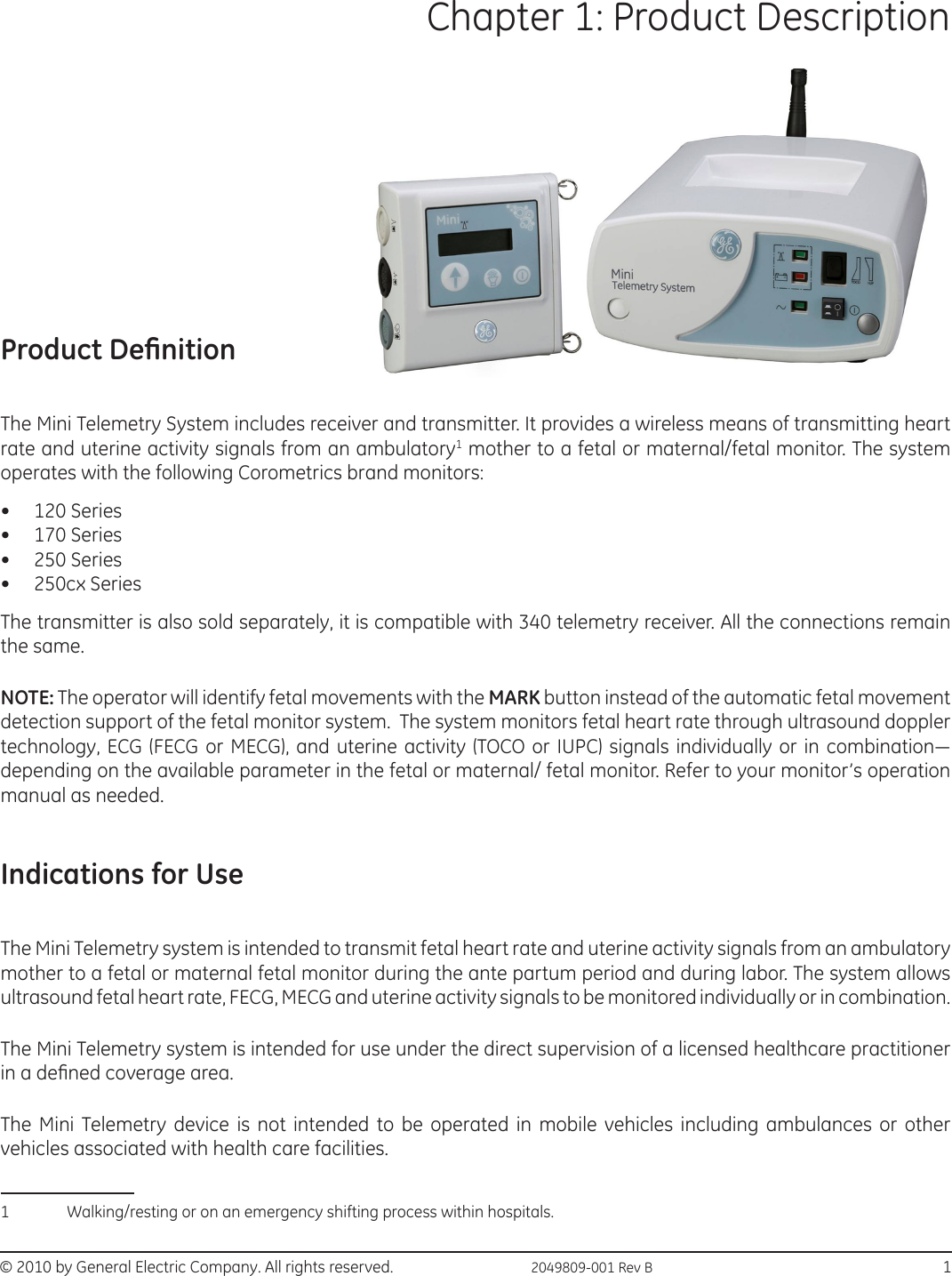
User Manual

Mini Telemetry Operation and Maintenance ManualGE HealthcareTo order this manual, please refer Appendix A for correct language listing.Copyright 2010 by General Electric Company.All rights reserved.2049809-001 Rev B.
All rights reserved. General Electric Company reserves the right to make changes in specications and features shown herein, or discontinue the product described at any time without notice or obligation. Contact your GE Representative for the most current information, Corometrics is a trade mark owned by GE Healthcare and GE monogram are trademarks of General Electric Company. All other company and product names mentioned may be trademarks of the companies with which they are associated.
©  2010 by General Electric Company. All rights reserved.  2049809-001 Rev B                                                                                                   iiiContentsAbout this Manual ........................................................................................................... viiUser Responsibility .................................................................................................................................................... viiConventions ................................................................................................................................................................. viiiDenition of Terms Used ....................................................................................................................................... viiiSymbol Denitions ...................................................................................................................................................... ixChapter 1: Product Description ...................................................................................... 1Product Denition ........................................................................................................................................................ 1Indications for Use .......................................................................................................................................................1Product Features .......................................................................................................................................................... 2Chapter 2: Safety ............................................................................................................... 3General Information  .................................................................................................................................................. 3General Use ....................................................................................................................................................................3Responsibility of the Manufacturer  ....................................................................................................................3Equipment Safety Information...............................................................................................................................4FCC Information (USA) ................................................................................................................................................8FCC Rules Compliance ......................................................................................................................................8FCC RF Exposure Compliance .......................................................................................................................8FCC Service Information .................................................................................................................................. 8Wireless Medical Telemetry Service (USA) ...............................................................................................8Industry Canada Information  ................................................................................................................................9Transmitter Antenna  ........................................................................................................................................ 9Interference  ..........................................................................................................................................................9Wireless Medical Telemetry Service  ..........................................................................................................9CE Marking Information Compliance ..................................................................................................................9R&TTE directive .......................................................................................................................................................... 10Chapter 3: Mini Telemetry Components .....................................................................11Transmitter  ................................................................................................................................................................. 11Oblique View ...................................................................................................................................................... 11Side View .............................................................................................................................................................. 13Battery Compartment.................................................................................................................................... 14Display GUI .......................................................................................................................................................... 15
iv                                                 2049809-001 Rev B    © 2010 by General Electric Company. All rights reserved.Table of ContentsDisplay Indications .......................................................................................................................................... 15Receiver ......................................................................................................................................................................... 16Receiver Front Panel ....................................................................................................................................... 16Receiver Rear Panel ........................................................................................................................................ 17Chapter 4: Installation and Setup ................................................................................19Connecting the Receiver and Monitor  ........................................................................................................... 19Setting up the Transmitter  ................................................................................................................................... 21Connecting Battery to Circuit Board ....................................................................................................... 21Connecting Power Adaptor ......................................................................................................................... 22Replacing the Plug Attachments .............................................................................................................. 23Attaching the Carrying Strap ...................................................................................................................... 23Performing a Functional Checkout  .................................................................................................................. 24Initial Conditions  .............................................................................................................................................. 24Testing the Radio Frequency ...................................................................................................................... 24Testing the Ultrasound Functions  ........................................................................................................... 25Testing the ECG Functions ........................................................................................................................... 26Testing the UA Functions .............................................................................................................................. 27Testing the Event Marker Function .......................................................................................................... 29Testing the Environment  ............................................................................................................................. 29Monitoring via Telemetry ....................................................................................................................................... 30Suggestions for Ambulatory Monitoring ............................................................................................... 30Monitoring Reminders ............................................................................................................................................ 31General ................................................................................................................................................................. 31Ultrasound  ......................................................................................................................................................... 32FECG  ...................................................................................................................................................................... 32Tocotransducer  ................................................................................................................................................ 32IUPC  ....................................................................................................................................................................... 32Chapter 5: Maintenance and Cleaning .......................................................................33Maintenance ............................................................................................................................................................... 33Storage ................................................................................................................................................................. 33General Cleaning Precautions ................................................................................................................... 33Cleaning the Transmitter and Receiver ................................................................................................. 33Shoulder Strap Cleaning ............................................................................................................................... 34Chapter 6: Troubleshooting ..........................................................................................35Problem Chart............................................................................................................................................................. 35
©  2010 by General Electric Company. All rights reserved.  2049809-001 Rev B                                                                                                   vTable of ContentsAppendix A: Supplies and Accessories ........................................................................41Appendix B: Technical Specications ..........................................................................43B.1 Transmitter ........................................................................................................................................................... 43B.2 Receiver ................................................................................................................................................................. 48Appendix C: Electromagnetic Compatibility ..............................................................51C.1 Electromagnetic compatibility (EMC) guidance................................................................................... 51C.2 Manufacturer’s guidance and declaration regarding electromagnetic immunity ............ 51Appendix D: Warranty ....................................................................................................55
vi                                                 2049809-001 Rev B    © 2010 by General Electric Company. All rights reserved.Table of ContentsThis page is left blank intentionally.
© 2010 by General Electric Company. All rights reserved.  2049809-001 Rev B                                                                       viiAbout this ManualBefore using the Mini Telemetry System with your Corometrics Fetal Monitor, read this entire manual. As with all medical equipment, attempting to use this device without a thorough understanding of its operation may result in patient or user injury. This device should only be operated by personnel trained in its operation and familiar with the risks and benets of this type of device. Additional precautions specic to certain procedures are found in the text of this manual.User ResponsibilityThis Product will perform in conformity with the description contained in this Operation and Maintenance manual and accompanying labels and/or inserts, when assembled, operated, maintained and repaired in accordance with the instructions provided. This Product must be checked periodically. A defective Product should not be used. Parts that are broken, missing, partially worn, distorted, or contaminated should be replaced immediately. Should such repair or replacement become necessary, GE Healthcare recommends that a telephonic or written request for service advice be made to the nearest GE Healthcare Regional Service Center. This Product or any of its parts should not be repaired other than in accordance with written instructions provided by GE Healthcare and by GE Healthcare trained personnel. The Product must not be altered without GE Healthcare’s prior written approval. The user of this Product shall have the sole responsibility for any malfunction that results from improper use, faulty maintenance, improper repair, damage, or alteration by anyone other than GE Healthcare. Do not use this product without prior site survey and awareness of the standard medical frequency bands that can be congured for this Telemetry system.GE Healthcare has declared that this product conforms with the European Council Directive 93/42/EEC Medical Device Directive when used in accordance with the instructions provided in this Operation and Maintenance Manual.U.S. Federal law restricts this device to sale by or on the order of a licensed medical practitioner.
viii                                                  2049809-001 Rev B   © 2010 by General Electric Company. All rights reserved.About this ManualConventionsVarious types of pictures or icons are used in this manual wherever they reinforce the printed message to alert you to potential safety hazards.The warnings and cautions in this section relate to the equipment in general and apply to all aspects of the equipment. Be sure to read the other chapters as they contain additional warnings and cautions that relate to specic features of the equipment.When grouped, warnings and cautions are listed alphabetically and do not imply any order of importance.WARNING:A  DANGER notice indicates an imminently hazardous situation which, if not avoided, will result in death or serious injury.CAUTION:A  CAUTION indicates a potentially hazardous situation which, if not avoided, may result in minor or moderate injury.  Cautions are also used to avoid damage to equipment.SENSITIVE TO ELECTROSTATIC DISCHARGE CAUTIONAn Electrostatic Discharge (ESD) Susceptibility symbol is displayed to alert service personnel that the part(s) are sensitive to electrostatic discharge and that ESD control guidelines must be followed to prevent damage to the equipment.NOTE: A Note provides important information about an item or a procedure. Information contained in Notes can often save you time or eort.Denition of Terms UsedThe denitions of terms used in this manual are listed in the following table:Term DenitionECG ElectrocardiogramMECG Maternal ElectrocardiogramFHR Fetal Heart RateUA Uterine ActivityTOCO Non invasive method of measuring uterine activity IUPC Intra-Uterine Pressure CatheterRF Radio FrequencyBPM Beats Per MinuteFECG Fetal ElectrocardiogramWMTS Wireless Medical Telemetry System
© 2010 by General Electric Company. All rights reserved.  2049809-001 Rev B                                                                       ixAbout this ManualTerm DenitionESD Electro Static DischargeBNC Bayonet Nut ConnectorSymbol DenitionsThis section identies the symbols that are displayed on the Mini Telemetry.Symbol DenitionRefer to instruction manual / booklet.Protective earth terminal        Alternating currentEuropean Union representativeSerial numberManufacturerEquipment shall be used only by qualied, trained medical personnelNon-sterileWaste of electrical and electronic equipment must not be disposed as unsorted municipal waste and must be collected separatelyGround Equalization Potential PostE CR E PSN
x                                                  2049809-001 Rev B   © 2010 by General Electric Company. All rights reserved.About this ManualSymbol DenitionBattery Runtime IndicatorIEC TYPE B EQUIPMENT. Type B equipment is suitable for intentional, external and internal application to the patient, excluding direct cardiac application.IEC TYPE BF EQUIPMENT. Type BF equipment is suitable for intentional external and internal application to the patient, excluding direct cardiac application. Type BF equipment has an F-type applied part.IEC  TYPE  CF  EQUIPMENT:  Type  CF  equipments  provide the  highest  degree of patient protection. This degree of protection is achieved by increased isolation from earthed parts and other accessible parts of the equipment, further limiting the  magnitude  of  possible  current ow through the patient.  Type CF applied parts are suitable for direct cardiac application.DEFIBRILLATOR-PROOF TYPE BF EQUIPMENT: Type BF equipment is suitable for intentional external and internal application to the patient, excluding direct cardiac appliction.  Type BF equipment is type B equipment with an F-type isolated (oating) part. The paddles indicate the equipment is debrillator proof.0POWER OFF: disconnection from the mains.IPOWER ON: connection to the mains.1.  Use Transducer in a watery environment only when connected to a telemetry system. Do not allow the telemetry system to get wet.2.  Do not use transducer in a watery environment when directly connected to a fetal/maternal monitor that is directly connected to AC line power.Date of Manufacture (in “YYYY-MM” format) Elevated, potentially hazardous levels of non-ionizing radiation.UltrasoundECG
© 2010 by General Electric Company. All rights reserved.  2049809-001 Rev B                                                                       xiAbout this ManualSymbol DenitionUterine ActivityClass II equipment according to IEC 61140.CE Mark for devices to be sold in the EU.Electrical equipment which is not suitable for a residential area (e.g. equipment which produces radio interference when in operation).Prescription Device Label for United States.Unique Identication number from FCC and Industry Canada.Medical EquipmentWith respect to electric shock, re and mechanical hazard only in accordance with UL.Direct Current for products to be powered from DC supply.Mark key symbol.Speaker Symbol ( IEC 5080 symbol).
xii                                                  2049809-001 Rev B   © 2010 by General Electric Company. All rights reserved.About this ManualTransmitter Power ON / OFF (IEC 5010 symbol).Audio head set  (IEC 5077 symbol).Fuse Symbol (IEC 5016 symbol).Antenna Symbol (IEC 5039 symbol).To identify a connector for a serial data connection.Named as  “ J2 “ on the Receiver back panel (IEC 5850 symbol).To identify an output terminal when it is necessary to distinguish between inputs and outputs.Named as “J1 “on the Receiver back panel (IEC 5035 symbol).Signal Strength Indicator on receiver front panel.Battery Symbol on Receiver front panel (ISO 0247 symbol).Temperature limitations in which the transport package has to be kept and handled.Humidity limitations in which the transport package has to be kept and handled.
© 2010 by General Electric Company. All rights reserved.  2049809-001 Rev B                                                                       xiiiAbout this ManualPressure limitations in which the transport package has to be kept and handled.NOTE: Mini-telemetry system is not made with natural rubber latex.
xiv                                                  2049809-001 Rev B   © 2010 by General Electric Company. All rights reserved.About this ManualThis page is left blank intentionally,
© 2010 by General Electric Company. All rights reserved.  2049809-001 Rev B                                                                           1Chapter 1: Product Description Product DenitionThe Mini Telemetry System includes receiver and transmitter. It provides a wireless means of transmitting heart rate and uterine activity signals from an ambulatory1 mother to a fetal or maternal/fetal monitor. The system operates with the following Corometrics brand monitors:•  120 Series•  170 Series•  250 Series•  250cx SeriesThe transmitter is also sold separately, it is compatible with 340 telemetry receiver. All the connections remain the same. NOTE: The operator will identify fetal movements with the MARK button instead of the automatic fetal movement detection support of the fetal monitor system.  The system monitors fetal heart rate through ultrasound doppler technology, ECG (FECG or MECG), and uterine activity (TOCO or  IUPC) signals individually or in combination— depending on the available parameter in the fetal or maternal/ fetal monitor. Refer to your monitor’s operation manual as needed.Indications for UseThe Mini Telemetry system is intended to transmit fetal heart rate and uterine activity signals from an ambulatory mother to a fetal or maternal fetal monitor during the ante partum period and during labor. The system allows ultrasound fetal heart rate, FECG, MECG and uterine activity signals to be monitored individually or in combination.The Mini Telemetry system is intended for use under the direct supervision of a licensed healthcare practitioner in a dened coverage area.The Mini Telemetry device is not intended to be operated in mobile vehicles including ambulances or other vehicles associated with health care facilities. 1 Walking/resting or on an emergency shifting process within hospitals.
2                                                  2049809-001 Rev B   © 2010 by General Electric Company. All rights reserved.Chapter 1: Product DescriptionProduct FeaturesThe Mini Telemetry oers the following features:•  Battery operated transmitter which provides up to 12 hours2  of continuous transmission when charged for a period of 4 hours.•  Low Battery indicator accompanied by an audio indicator which signals an impending low-battery condition.•  Transmitter  headset  which  allows  the  patient  or  sta  to  hear  the  heartbeats  detected  ultrasonically  for reassurance as well as to verify proper transducer placement.•  Signal strength indicator that veries the strength of the radio transmission signal.•  Interchangeable  Transducers:  Transducers  are  quickly  and  easily  interchangeable  amongst  the  Mini Telemetry System and Corometrics brand monitors. Following is the list of monitors:•  120 Series: Transducers are interchangeable.3•  170 Series: Transducers are interchangeable.•  250 Series: Transducers are interchangeable.3•  250cx Series: Transducers are interchangeable.3•  Simultaneous  monitoring  of  two  heart  rates  (twins)  when  used  with  a  monitor  supporting  parameters: Ultrasound FHR and FECG.•  Display to view the battery charge status, audio volume status and channel frequency.•  External power adaptor to charge the internal battery.•  Groove on the transmitter for cable management.•  In-built Mark key on the transmitter to transmit fetal movement information.•  Quick charge feature which provides up to 150 minutes of continuous transmission with just 30 minutes of charging.•  Can be used during laboring in water/showers.42  Use of the headset and the speakers will deplete the battery charge more rapidly.3            Round connector cables are compatible whereas ECG rectangular connector cables are not compatible.4  Refer to Warnings, Cautions and Notes section.
© 2010 by General Electric Company. All rights reserved.  2049809-001 Rev B                                                                                  3Chapter 2: SafetyThe information presented in this section is important for the safety of both the patient and operator and also serves to enhance equipment reliability.  This chapter describes how the terms Danger, Warning, Caution, Important and Note are used throughout the manual. In addition, standard equipment symbols are dened.General Information General UseIf any equipment is cold to the touch or below ambient temperature, allow it to stabilize to ambient temperature before use. To ensure patient safety, use only parts and accessories manufactured or recommended by GE Medical Systems Information Technologies. Parts and accessories used shall meet the requirements of IEC 60601-1. Disposable devices are intended for single use only. They should not be reused. Periodically and whenever the integrity of the equipment is in doubt, test all functions as indicated under the section “Chapter 4: Installation and Setup” on page 19. Refer to the “Maternal/Fetal Monitoring Operator’s Manual” for information concerning the limitations of internal and external fetal heart rate monitoring techniques. Responsibility of the Manufacturer GE Medical Systems Information Technologies (hereafter Information Technologies) is responsible for the eects on safety, reliability and performance if: •  Assembly  operations,  extensions,  readjustments,  modications,  or  repairs  are  carried  out  by  persons authorized by Information Technologies.•  The electrical installation of the relevant room complies with appropriate regulations.•  The equipment is used in accordance with the instructions for use.
4                                                 2049809-001 Rev B   © 2010 by General Electric Company. All rights reserved.Chapter 2: SafetyEquipment Safety InformationThe following table contains warnings for this manual. A Warning statement is used when the possibility of injury to the patient or the operator exists.WARNINGDo not place Mini-telemetry Transmitter on Receiver’s cavity while using Telemetry. There are chances of faulty/erratic parametric readings being displayed on the monitor.WARNINGPeriodically check for ECG QRS complex trace if the monitor has an option for displaying waveform. If random FHR / MHR / UA is observed on the strip chart paper /monitor display, please re-check the transducer position. If the base line noise of ECG trace is observed to be high, there are chances of faulty random FHR being displayed on the monitor.WARNINGACCIDENTAL SPILLS—In the event that  uids  are accidentally spilled  on  the  equipment,  take  the equipment out of operation and inspect for damage.WARNINGCONDUCTIVE CONNECTIONS—Avoid making any conductive connections to applied parts (patient connection) which are likely to degrade safety.WARNINGCONDUCTIVE  PARTS—Ensure  that  the  conductive  parts  of  the  lead  electrodes  and  associated connectors do not contact other conductive parts including earth.WARNINGDEFIBRILLATION—This equipment is not designed for use with debrillators.WARNINGELECTRICAL  SHOCK—To  reduce  the  risk  of  electrical  shock,  do  not  remove  equipment  covers.  Contact qualied personnel for servicing.WARNINGELECTROMAGNETIC  INTERFERENCE—Be  aware  that  strong  electromagnetic  elds  may  interfere with equipment operation.  Interference prevents the clear reception of signals by the device.  If the hospital is close to a strong transmitter such as TV, AM or FM radio, police or re stations, a HAM radio operator, an airport, pager or cellular phone, their signals could be picked up as signals by the equipment.  If you feel interference is aecting the equipment, contact your Service Representative to check the equipment in your environment.WARNINGELECTROSURGERY—The equipment is not designed for use with high-frequency surgical devices.  In addition, measurements may be aected in the presence of strong electromagnetic sources such as electrosurgery equipment.
© 2010 by General Electric Company. All rights reserved.  2049809-001 Rev B                                                                                  5Chapter 2: SafetyWARNINGEXPLOSION HAZARD—Do not use this equipment in the presence of ammable anesthetics or inside an oxygen tent.WARNINGFREQUENCY ALLOCATION- Frequencies of the receiver and transmitter have to be allocated. Refer to Service Manual for the  list of channel numbers.WARNINGINSTRUCTIONS—For continued and safe use of this equipment, it is necessary to follow all listed instructions.  However, the instructions provided in this manual in no way supersede established medical procedures concerning patient care.  The device does not replace observation and evaluation of the patient, at regular intervals, by a qualied care provider who will make diagnoses and decide on treatments and interventions.WARNINGINTERFACING  OTHER  EQUIPMENT—Monitoring  equipment  must  be  interfaced  with  other  types of  medical  equipment  by  qualied  biomedical  engineering  personnel.    Be  certain  to  consult manufacturers’ specications to maintain safe operation.WARNINGBATTERY- Check battery low audio alarm and timely recharge the battery.WARNINGACCESSORY- Use GE recommended accessories/power adaptor as listed in the accessory list.WARNINGRECEIVER PLACEMENT- Receiver has to be placed on at surface.WARNINGTRANSDUCER CABLES- Remove transducer cables while transmitter is placed on the receiver.WARNINGCLEANING AGENTS- Use recommended cleaning agents.WARNINGMONITORING THROUGH CENTRAL NURSING STATION - Periodic monitoring of the mother has to be done while monitoring through central nursing station.WARNINGINTENDED USE- Intended use of telemetry is for ambulating mother.WARNINGSPEAKER- Do not block speaker vents.WARNINGLINE  ISOLATION  MONITOR  TRANSIENTS—Line  isolation  monitor  transients  may  resemble  actual cardiac waveforms and thus cause incorrect heart rate determination and alarm activation (or inhibition).
6                                                 2049809-001 Rev B   © 2010 by General Electric Company. All rights reserved.Chapter 2: SafetyWARNINGMRI  USE—Do  not  use  the equipment  during  MRI    scanning,  conducted current could potentially cause burns.WARNINGDo not charge transmitter during shower/laboring in water.WARNINGSHOWER- Keep the transmitter away from water source.WARNINGLEAKAGE CURRENT TEST—The interconnection of auxiliary equipment with this device may increase the total leakage current. When interfacing with other equipment, a test for leakage current must be performed by qualied biomedical engineering personnel before using with patients.  Serious injury or death could result if the leakage current exceeds applicable standards. The use of accessory equipment not complying with the equivalent safety requirements of this equipment may lead to a reduced level of safety of the resulting system.  Consideration relating to the choice shall include: use of the accessory in the patient vicinity and evidence that the safety certication of the accessory has been performed in accordance with the appropriate IEC 60601-1 harmonized national standard.WARNINGPATIENT CABLES AND LEADWIRES—Do not use patient cables and electrode leads that permit direct connection to electrical sources.  Use only “safety” cables and lead wires . Use of non-safety patient cables and lead wires  creates risk of inappropriate electrical connection which may cause patient shock or death.WARNING PACEMAKER PATIENTS—Rate meters may continue to count the pacemaker rate during occurrences of cardiac arrest or some arrhythmias. Do not rely entirely upon rate meter alarms.  Keep pacemaker patients under close surveillance.  Refer to your monitor’s operation manual for disclosure of the pacemaker pulse rejection capability.WARNINGSIMULTANEOUS DEVICES—Do not simultaneously connect more than one device that uses electrodes to detect ECG and/or respiration to the same patient. Use of more than one device in this manner may cause improper operation of one or more of the devices.WARNINGSTRANGULATION—Make sure all patient cables, leadwires and tubing are positioned away from the patient’s head to minimize the risk of accidental strangulation.WARNINGNot suggested to connect the transducer to mother while transmitter is placed on receiver/and charging, as it may result in accidental drop of the transmitter from the receivers’ locationWARNINGLABORING IN WATER— Ensure that Mini Telemetry transmitter (excluding transducer) does not come in direct contact with water. Failure to do so may result in electrical shock hazard. WARNINGEQUIPMENT  MODIFICATION:  No  modication  of  this  equipment  is  allowed.  Do  not  modify  this equipment without authorization of the manufacturer. If  this equipment is modied, appropriate inspection and testing must be conducted to ensure continued safe use of the equipment.
© 2010 by General Electric Company. All rights reserved.  2049809-001 Rev B                                                                                  7Chapter 2: SafetyWARNINGRECEIVER CONNECTORS: Operator shall not touch the J1 and J2 connector at the back plate of the Receiver and the patient simultaneouslyWARNINGINTERFERENCE:  The use of TENS (Transcutaneous Electrical Nerve Stimulation) used for pain relief in labor can interfere with fetal/maternal monitoring with Coro monitors.WARNINGAPPLIED PARTS: Audio headset and the transducer cables can also come in contact with the patient other than the labeled applied parts. These are classied as Type B.WARNINGBATTERY: Only GE authorized / recommended battery pack shall be used to avoid wrong mounting of battery, dangers related to polarity reversal, short circuit or ames.The following table contains cautions for this manual. A Caution statement is used when the possibility of damage to the equipment exists.CAUTIONMini Telemetry services shall be done only by authorized service personnel.CAUTIONANNUAL SERVICING—For continued safety and performance of the equipment, it is recommended that the calibration, accuracy and electrical safety of the equipment be veried on an annual basis by an Information Technologies Service Representative.CAUTIONDAILY INSPECTION—It is essential that the equipment and accessories be inspected prior to every use.CAUTIONENVIRONMENT—The performance of the equipment has not been tested in certain areas, such as x-ray and imaging suites.  The equipment is not recommended for use in these environments.CAUTIONPERFORMANCE—Report  all  problems  experienced  with  the  equipment.  If  the  equipment  is  not working properly, contact your Service Representative for service. The equipment should not be used if it is not working properly.CAUTIONCheck the health of the line voltage. Few hospital sites may nd noise in FECG/MECG when used with power adaptor.CAUTIONPeriodic check needs to be done for mother’s parameter by the caregiver to ensure uninterrupted monitoring.CAUTIONAvoid over charging the battery or shorting the battery terminals.CAUTIONSTANDARD  MAINTENANCE:  Standard  maintenance  must  be  performed  by  authorized  service personnel for the lifetime of the product (7 years).CAUTIONULTRASOUND TRANSDUCER: Visually inspect the ultrasound transducer on a regular basis to ensure there are no cracks or damages around the transducer face, cable, strain relief and connector pins.
8                                                 2049809-001 Rev B   © 2010 by General Electric Company. All rights reserved.Chapter 2: SafetyFCC Information (USA)FCC Rules ComplianceTelemetry  FCC Rules ComplianceMini Telemetry System FCC 47 CFR Part 95This equipment complies with the FCC rules  shown in above Table. Operation is subject to the condition that this device does not cause harmful interference.FCC RF Exposure ComplianceImportant :  RF  EXPOSURE—To  comply  with  FCC  RF  exposure  compliance  requirements,  users  should  avoid grasping the antenna for any extended period of time while the device is in operation.FCC Service InformationServicing the radio frequency transmitter and receiver sections of the Mini Telemetry System requires an FCC General Radio Telephone License. Any changes or modications made to the Mini Telemetry System that are not expressly approved by Information Technologies, could void the user’s authority to operate this equipment. Wireless Medical Telemetry Service (USA)This section applies to Mini Telemetry Systems used in USA only. IMPORTANT: FREQUENCY COORDINATOR—Operation of a Mini Telemetry System requires prior coordination with a frequency coordinator designated by the FCC for the Wireless Medical Telemetry Service.In June 2000, the FCC allocated new spectrum and established rules for Wireless Medical Telemetry Service (WMTS) allowing potentially life-critical equipment to operate on an interference-protected basis. The frequency allocation for WMTS provides spectrum where the equipment can operate on a primary basis increasing the reliability of this important service. The FCC allocated 14 MHz of spectrum for use by medical telemetry equipment in the 608–614 MHz, 1395–1400 MHz and 1429–1432 MHz bands. This allocation was based on a needs assessment conducted by the American Hospital Association (AHA). The 608–614 MHz band, which corresponds to TV channel 37 had been reserved for radio astronomy uses, so this action elevates medical telemetry to a co-primary status with radio astronomy in this band. The 1395–1400 MHz and 1429–1432 MHz bands were government bands reallocated for non-government use. WMTS is designated as one of the Citizen’s Band Services in Part 95 of the rules and licensed by rule to eliminate the possible costs and delays to obtain individual operator’s licenses. The medical telemetry equipment is
© 2010 by General Electric Company. All rights reserved.  2049809-001 Rev B                                                                                  9Chapter 2: Safetyauthorized under the certication procedure in Part 2 of the rules. One or more frequency coordinators maintain a database of all equipment used in conjunction with WMTS. For more information visit http://www.fcc.govIndustry Canada Information The Mini Telemetry System complies with Industry Canada RSS-210 . Transmitter Antenna The Mini Telemetry Transmitter has been designed to operate with an antenna having a maximum gain of 6 dBi. Antenna having a higher gain is strictly prohibited as per regulations of Industry Canada. The required antenna impedance is 50 Ω. Interference Mini-telemetry System operation is subject to the following two conditions: 1.  This device may not cause interference.2.  This device must accept any interference, including interference that may cause undesired operation of the device. Wireless Medical Telemetry Service The Mini Telemetry System is only permitted for installation in hospitals and health care facilities. Devices shall not be operated in mobile vehicles (even ambulances and other vehicles associated with health care facilities). The installer/user of this device shall ensure that it is at least 80 km from the Penticton radio astronomy station (British Columbia latitude: 49° 19’ 12” N: longitude: 118° 59’ 56” W). For medical telemetry systems not meeting this 80 km separation (e.g. the Okinagan valley, British Columbia) the installer/user must coordinate with and obtain the written concurrence of the Director of the Penticton radio astronomy station before the equipment can be installed or operated. The Penticton contact  is Tel: 250-493-2277/fax: 250-493-7767. CE Marking Information ComplianceThe Mini Telemetry System bears CE mark CE-0459 indicating conformity with the provisions of the Council Directive 93/42/EEC concerning medical devices and fullls the essential requirements of Annex I of this directive. The product is radio-interference protection class A in accordance with EN 55011The country of manufacture can be found on the equipment labeling.
10                                                 2049809-001 Rev B   © 2010 by General Electric Company. All rights reserved.Chapter 2: SafetyThe product complies with the requirements of the standard EN 60601-1-2 “Medical Electrical Equipment - Part 1-2:  General  requirements for safety  -  Collateral  standard:  Electromagnetic compatibility  -  Requirement and tests.”The safety and eectiveness of this device has been veried against previously distributed devices. Although all standards applicable to presently marketed devices may not be appropriate for prior devices (i.e. electromagnetic compatibility  standards),this  device  will  not  impair  the  safe  and  eective  use  of  those  previously distributed devices.R&TTE directiveThe Mini Telemetry transmitter and receiver system conform to the R&TTE Directive 1999/5/EC.
© 2010 by General Electric Company. All rights reserved.  2049809-001 Rev B                                                                               11Chapter 3: Mini Telemetry ComponentsThis section describes all controls, indicators and connectors on a Mini Telemetry System.Transmitter Oblique ViewThe following table describes the components of the Transmitter front panel:Component Description1.  Display:A display to show the charge status of battery, volume, connectors connectivity, Channel number and mark key.2.  Mark Key: When the Mark key is pressed, one of the following mark prints (depending on the type and/or setting of the Corometrics monitor) on the strip chart paper of Corometrics monitor:•       :  The  event  marker  is  commonly  used  to record an “event.” This mark is available on all Corometrics brand monitors.•    : The fetal movement marker (default setting) is commonly used as an indication that the mother has perceived fetal movement. (Refer to your monitor’s operator’s manual to learn if your monitor supports this feature. Refer to your monitor’s service manual for information about enabling the option.)The event marker   is displayed on the transmitter display as long as the Mark key is pressed.NOTE: Mark key functionality will work only if atleast one transducer is connected to the transmitter.
12                                                  2049809-001 Rev B   © 2010 by General Electric Company. All rights reserved.Chapter 3:Mini Telemetry ComponentsComponent Description3.  Volume Key:If ultrasound transducer is connected, this key controls the  volume of fetal heartbeat, heard on the speaker/headphone. Multiple presses of this key will cycle the volume from mute to 5 volume levels. 4.  Power Key:Pressing the key once turns on the transmitter. Pressing the key for more than 2 seconds turns o the transmitter.5.  Ultrasound Input:Connect a Corometrics 5700 Series pulsed Doppler ultrasound transducer to this light grey receptacle. 6.  ECG Input: Connect an FECG cable/legplate or MECG cable plug to this grey receptacle. This connector is compatible with all round-connector FECG/MECG patient cables used with Corometrics-brand monitors.7.  UA Input:Connect a tocotransducer or IUPC transducer connector to this white receptacle. Contact your Sales Representative about compatibility.
© 2010 by General Electric Company. All rights reserved.  2049809-001 Rev B                                                                               13Chapter3 :Mini Telemetry ComponentsSide ViewThe following table describes the components of the Transmitter side panel:Component Description1.  O ring:Ring for attaching the carrying strap. 2.  DC in-let Connector:Connect the GE recommended power adaptor to this connector for charging the transmitter battery. WARNING:Always use only GE recommended power adaptor.3.  Headset Connector: Connect the headset to this receptacle to listen to the fetal heart rate derived from ultrasound. The transmitter has an option to wind transducer cables on the enclosure as a part of cable management.1.  A groove provided on the sides of transmitter to wind the long cables, especially used while mother is ambulating.
14                                                  2049809-001 Rev B   © 2010 by General Electric Company. All rights reserved.Chapter 3:Mini Telemetry ComponentsBattery CompartmentThe following table describes the components of the Transmitter battery compartment:Component DescriptionThe battery compartment holds 1 Lithium ion battery. Only authorized, trained personal shall open the battery compartment for any service related actions.CAUTION BATTERY STRENGTH—The transmitter emits an audible alarm when the transmitter battery is low. The onset of audio alarm indicates that, unless the transmitter battery is recharged, the transmitter will switch o    in  approximately  5  minutes.  If  the  transmitter battery is not recharged, the alarm continues until the transmitter switches o.WARNINGDo not block the speaker vents.
© 2010 by General Electric Company. All rights reserved.  2049809-001 Rev B                                                                               15Chapter3 :Mini Telemetry ComponentsDisplay GUIThe following table describes the Transmitter display GUI:Figure Description1.  Battery Charge Status: Indicates battery level and charge status. Indications continuously move while the battery is being charged.2.  Speaker Volume Status:5 levels of volume and mute are indicated. 3.  Mark Indicator:Arrow mark is visible for an additional second after the Mark key is released.4.  Channel Number:Channel number of the transmitter is displayed. Refer to the frequency chart in the service manual.5.  Transducer Connection Status:Indicates the connection status of the parametric connectors. Filled circle indicates connector plugged in, empty circle indicates connector not plugged in.Display IndicationsThe following table shows the transmitter display indications:Indication DescriptionIndicates speaker is mute.Indicates battery error.Indicates radio module error.
16                                                  2049809-001 Rev B   © 2010 by General Electric Company. All rights reserved.Chapter 3:Mini Telemetry ComponentsThe transmitter unit generates three distinct audio alerts in case of low battery conditions. A short beep alarm is generated when the battery charge goes below the low-charge limit. A long beep alarm is generated when the battery charge level is critical and immediate recharging is required. The alarm will be generated at a faster rate when the battery run-time left is about one minute until the battery is completely depleted and the unit automatically turns o. Alarm tones will be deactivated when the Mini Telemetry transmitter is connected to the external power adaptor for charging. ReceiverReceiver Front PanelThe following table describes the components of the Receiver front panel:Component Description1.  Signal Indicator The green Signal indicator lights continuously when the receiver is accepting radio frequency signals from the transmitter. The Signal indicator ashes if the signal strength is weak or marginal.2.  UA Mode Selector :This switch communicates the active uterine activity mode to the fetal or maternal/fetal monitor:•  When monitoring with a tocotransducer, set the switch to the TOCO position.•  When monitoring with an intrauterine pressure catheter, set the switch to the IUP position.3.  Low Battery IndicatorThe red battery indicator shows that the transmitter’s battery is low.4.  Power SwitchThe Power switch turns the receiver on (I) and o (O). When it is set to on, the green Power indicator illuminates.
© 2010 by General Electric Company. All rights reserved.  2049809-001 Rev B                                                                               17Chapter3 :Mini Telemetry ComponentsComponent Description5.  Channel Number: The channel number is the customer-designated frequency of the receiver. For each telemetry system, the channel number of the receiver must be identical to the channel number of the transmitter. Also, if you have more than one telemetry system, or other RF devices, each system must have a unique channel number.Receiver Rear PanelThe following table describes the components of the Receiver rear panel:Component Description1.  Equipotential Lug:Binding post terminal, which is directly connected to chassis, for use as an equipotentiality connector.2.  Transmitter Placeholder:Placeholder provided for the transmitter.3.  Antenna Connector:Twist-on connector for attaching the receiver antenna.4.  AC Line Connector and Fuseholder Module:This module houses the AC-line input connector and the main fuses for the receiver:•  100-120  VAC:  requires  two,  0.25  A  slow-blow fuses.•  220-240  VAC:  requires  two,  0.25  A  slow-blow fuses.
18                                                  2049809-001 Rev B   © 2010 by General Electric Company. All rights reserved.Chapter 3:Mini Telemetry ComponentsComponent Description5.  Power cord holder clamp:To hold the power cord.6.   Auxiliary Output ConnectorThis connector outputs the US, ECG, UA and Mark signals acquired by telemetry to a compatible fetal/fetal-maternal Monitor. See “Connecting the Receiver and Monitor” on page 19 for complete interconnection details. As soon as any telemetry mode is detected, the front panel of the compatible fetal/fetal-maternal monitor is disabled and all front panel inputs are ignored. In other words, telemetry and monitor modes cannot be mixed and matched, you must use either telemetry or direct monitoring only. For proper operation with 120, 170, 250 or 250cx Series monitors, disconnect all transducers from the front panel of the monitor.7.  Programming ConnectorThe channel number of receiver can be changed through the transmitter using programming connector. For more details, refer to Appendix B.2 of Mini-telemetry service manual.
© 2010 by General Electric Company. All rights reserved.  2049809-001 Rev B                                                                              19Chapter 4: Installation and SetupThis section contains step-by-step instructions for connecting and testing your Mini Telemetry System. IMPORTANT CHANNEL NUMBERS—Ensure that the receiver and transmitter are operating on the same frequency, the channel numbers must be identical. The channel number label is located on the top of the receiver and on the back panel of the transmitter. If you have more than one Telemetry system, make sure that each transmitter/receiver pair operates on a unique frequency.Connecting the Receiver and Monitor There is a single way of interconnection method between Telemetry receiver and fetal or maternal/fetal monitor. Check your monitor model number prior to making any connections. Models 126, 128, 129, 171, 172, 173, 174, 256, 259, 256cx, 259cxIMPORTANT: 120 SERIES COMMUNICATIONS OPTION — A 120 series monitor requires a communications Board in order to interface to a Mini Telemetry system. If your monitor does not have this option, an upgrade kit is available as cat. no. (REF) 1559BAO. Contact your service representative for more information. Perform the following steps to connect the receiver and monitor:Step InstructionsInstructions to position the Receiver:1.  Turn o both the monitor and the receiver.2.  Place the receiver on the cart, or on top of, or near, the monitor.Note: Model 250/250cx shown.
20                                                  2049809-001 Rev B  © 2010 by General Electric Company. All rights reserved.Chapter 4: Installation and SetupStep InstructionsInstructions to attach the Receiver Antenna:1.  Insert the receiver antenna into the antenna connector on the receiver rear panel as shown in  the  gure.  Rotate  the  attachment  collar  in  a clockwise direction until snug.NOTE:  A Remote Antenna Bracket, cat. no. (REF) 1441AAO, is  available for attaching the antenna when the receiver will be enclosed in a cart or cabinet. Refer to the Installation Instructions, part no. (REF) 14153AA, included with the bracket or contact your Biomedical Engineering Department for assistance. To attach the antenna to the BNC connector on the bracket, rotate the antenna attachment collar in a clockwise direction until snug. Instructions to attach the Monitor Interconnect Cable to a 120, 250 or 250cx Series Monitor:1.  Plug one end of the interconnection cable into the Auxiliary Output connector on the receiver rear panel. 2.  Plug the other end into J101 telemetry connector on the rear panel of the monitor.Instructions to attach the Monitor Interconnect Cable to a 170 Series Monitor:1.  Connect to the receptacle labeled Note: Use 1563AAO interconnect cable.
© 2010 by General Electric Company. All rights reserved.  2049809-001 Rev B                                                                              21Chapter4: Installation and SetupSetting up the Transmitter Connecting Battery to Circuit BoardNOTE: The battery of Mini-telemetry transmitter is shipped without being connected to the circuit board. Before using the telemetry transmitter, ensure that battery is connected to the circuit board. SENSITIVE TO ELECTROSTATIC DISCHARGE CAUTIONThis procedure involves handling of ESD sensitive parts. ESD control guidelines must be followed during this procedure to ensure that static charges are safely conducted to the ground and not through the sensitive device, to prevent damage to the equipment. Step InstructionsInstructions to connect battery to circuit board:1.  Use a T10 Torx screwdriver to remove the  battery compartment screw and washer.2.  Slide the battery cover out.
22                                                  2049809-001 Rev B  © 2010 by General Electric Company. All rights reserved.Chapter 4: Installation and SetupStep Instructions3.  Connect the battery to the Battery Connector on the circuit board. Perform step 2 and 1 in reverse order to complete the battery installation.Connecting Power AdaptorPerform the following steps to connect the power adaptor.Step InstructionsInstructions to connect the power adaptor:1.  Turn o the transmitter.2.   Locate the DC inlet jack and connect the DC adaptor and plug the adaptor to AC mains socket. 3.  Switch on the AC mains with specied AC voltage indicated in the specications. Charge the internal battery for 4hrs before using the Transmitter. Check for battery charge/full indication on the display.IMPORTANT : Power Adaptor —Use only the appropriate country specic plug attachments to the Adaptor. The Mini Telemetry system’s Adaptor comes with global plugin options.
© 2010 by General Electric Company. All rights reserved.  2049809-001 Rev B                                                                              23Chapter4: Installation and SetupReplacing the Plug AttachmentsPerform the following steps to replace the plug attachments.Step InstructionsInstructions to replace the plug attachment:1.  Press and hold the Release button as shown in  gure 1 and rotate  the  plug  attachment  anti-clockwise to release it from the adaptor.2.  Place the desired plug attachment on the adaptor. Press and hold the Release button as shown in gure 2 and rotate clockwise to attach the plug to the adaptor.Attaching the Carrying StrapPerform the following steps to attach the carrying strap.Step InstructionsInstructions to attach the carrying strap:1.  Secure the metal clips at each end of the carrying strap to the belt attachment loops on each side of the transmitter as shown in gures 1 and 2.2.  Adjust the strap length as per mother’s comfort for easy carrying.
24                                                  2049809-001 Rev B  © 2010 by General Electric Company. All rights reserved.Chapter 4: Installation and SetupPerforming a Functional Checkout Initial Conditions Step Instructions Connect the receiver to the monitor as described in “Connecting the Receiver and Monitor” section earlier in this chapter.Turn on the transmitter, receiver and monitor attached to the receiver.Testing the Radio FrequencyPerform the following steps to test the radio frequency.Step InstructionsInstructions to Test the Radio Frequency:1.  Check the status of the Signal indicator    on the receiver:•  Continuous Green: Indicates that the receiver is accepting the radio frequency signals from the transmitter and the signal strength is good.  •  Flashing Green: Indicates the signal strength is weak or marginal. 2.  Check the status of the Battery indicator    on the receiver: •  O  :  The  transmitter  battery  is  adequately charged. •  Blinking/Continuous Red: The transmitter battery is low and should be recharged before further patient use.
© 2010 by General Electric Company. All rights reserved.  2049809-001 Rev B                                                                              25Chapter4: Installation and SetupTesting the Ultrasound Functions NOTE: TRANSDUCER TYPE—Use only Corometrics 5700 Series Ultrasound Transducers with the Mini Telemetry System. Perform the following steps to test the ultrasound functions:Step InstructionsInstructions to Test Ultrasound Functions:1.  Plug an ultrasound transducer into the Ultrasound connector on the transmitter as shown in the gure.2.  Verify the following: •  Ultrasound transducer connector status indication  is  reected  on  the  transmitter display.•  FHR value on the monitor shows “– – –”. •  Telemetry connected symbol will be printed on the strip chart paper. Additionally, Telemetry symbol will be displayed on Corometrics 120, 250 and 250cx series monitor.If “_ _ _” is not displayed on the monitor, ensure that the  corresponding  interconnection  cable  is  rmly attached to both the monitor and the receiver. 3.  Use  your  nger  to  gently  rub  the  ultrasound transducer surface in a rhythmic manner to simulate a FHR. Try to maintain a steady rate and verify  the  following  on  the  monitor:  (Alternative method – place the transducer in  the palm of your hand and rhythmically tap the top of your hand to simulate heartbeat.)•  The corresponding FHR display value responds to the rubbing.•  The corresponding FHR heartbeat indicator   responds to the input.•  The ultrasound audio tones are synchronous with the transducer stroking.
26                                                  2049809-001 Rev B  © 2010 by General Electric Company. All rights reserved.Chapter 4: Installation and SetupStep Instructions4.  Plug the headset into the transmitter’s headset connector  5.  Rub the face of the ultrasound transducer. Verify that you hear ultrasound audio tones from both sides of the headset or in the internal speakers (if head set is not connected)Testing the ECG Functions Perform the following steps to test the ECG functions.Step InstructionsInstructions to test the ECG functions:1.  Plug an ECG transducer into the ECG connector on the transmitter as shown in the gure.2.  Verify the following on the monitor: •  ECG transducer connector status indication is reected on the transmitter display.•  Telemetry connected symbol will be printed on the strip chart paper. Additionally, Telemetry symbol will be displayed on Corometrics 120, 250 and 250cx series monitor.
© 2010 by General Electric Company. All rights reserved.  2049809-001 Rev B                                                                              27Chapter4: Installation and SetupTesting the UA FunctionsPerform the following steps to test the UA functions.Step InstructionsInstructions to test UA functions:1.  Place the receiver’s UA Mode Selector switch in the TOCO position. IMPORTANT :TRIMLINE  TOCOTRANSDUCERS—If  the  monitor  is on when you connect or re-connect a Trimline Tocotransducer to the UA connector, you must wait at least 10 seconds before pressing the UA Reference button. If the monitor is o, you must wait at least 10 seconds from the time the monitor is powered on. 2.  Plug a tocotransducer into the transmitter’s UA connector as shown in the gure. Verify that,  •  UA transducer connector status indication is reected on the transmitter display.•  Telemetry connected symbol will be printed on the strip chart paper. Additionally, Telemetry symbol will be displayed on Corometrics 120, 250 and 250cx series monitor.•  An arbitrary pressure value is displayed on the monitor. IMPORTANT:DEFAULT  REFERENCE  VALUE—Most  monitors  have a default UA reference of 10 relative units. Take into consideration that newer model monitor’s can be congured to store a custom default value. 3.  Press the monitor’s UA Reference button to set the UA value to 10 relative units. Verify that Toco value on the monitor display shows 10 relative units.
28                                                  2049809-001 Rev B  © 2010 by General Electric Company. All rights reserved.Chapter 4: Installation and SetupStep Instructions4.  Apply gentle pressure to the tocotransducer pressure sensing button and verify that the monitor (display or uterine activity trace) responds to the pressure input. Increasing force should produce an increasing value and vice versa. If no pressure changes are recorded, ensure that the corresponding interconnection cable is rmly attached to both the monitor and the receiver.NOTE: Refer  respective  operator  manual  of  the  fetal monitor.5.  This step applies to monitors which support IUP monitoring. Place the receiver’s UA Mode Selector switch in the IUP position. Verify the following on the monitor: •  Corometrics 120, 250, 250cx series monitor :   “IUP” will be displayed on the monitor as the UA mode. •  Corometrics 170 series monitor: Turn on the strip chart recorder and check that the “IUP” annotation is printed on the paper. NOTE: Place the UA Mode Selector switch back in the TOCO position unless you plan to monitor with an IUPC.
© 2010 by General Electric Company. All rights reserved.  2049809-001 Rev B                                                                              29Chapter4: Installation and SetupTesting the Event Marker FunctionPerform the following steps to test the event marker function.Step InstructionsInstructions to test the event marker function:1.  Connect any transducer to the Mini-telemetry transmitter. Turn on the monitor’s strip chart recorder. NOTE: Mark key functionality will work only if atleast one transducer is connected to the transmitter.2.  Press the  Mark key on the transmitter for at least one second. Verify that an appropriate mark is printed on the paper and    appears on the transmitter display. NOTE: The settings for the mark should to be done in the monitor.•  :  This  annotation  is  commonly  used  to record an event. This mark is available on all Corometrics-brand monitors. •  : This  annotation is commonly used  as  an indication that the mother has perceived fetal movement. (Refer to the operator’s manual for your monitor to learn if your monitor supports this feature. Refer to the service manual of your monitor for information about enabling the option.) Testing the Environment Decide on which areas of your facility will be used for ambulatory monitoring. Test each location separately to rule out rooms that are restricted due to solid concrete walls, metal structures blocking signal transmission. Biomedical engineer or installation team will identify and manage distance measurements to ensure optimal signal clarity.
30                                                  2049809-001 Rev B  © 2010 by General Electric Company. All rights reserved.Chapter 4: Installation and SetupMonitoring via TelemetryThis section provides a brief overview of telemetry monitoring procedures. Refer to the “Maternal/Fetal Monitoring Operator’s Manual” for patient application information. Also refer to your monitor’s operator manual.Suggestions for Ambulatory MonitoringIMPORTANT :DESIGNATED AREAS—Show the patient the areas that are within signal range and where signal reception is clear.  The designated area is determined at the time of installation.Following are the suggestions for ambulatory monitoring:1.  Instruct the patient to wear the transmitter with the enclosure faced towards the receiver when possible. 2.  Adjust the carrying strap to a comfortable length. 3.  Encourage the patient to walk in a smooth, gliding motion. It is preferable to slide feet instead of moving quickly which may cause bouncing and artifact. 4.  Instruct the patient, following each fetal movement, to listen via the headset or speaker, for continued “pickup” of fetal heart rate tones. NOTE: Transducers with short cables are available. Contact your Information Technologies Sales representativePerform the following precautionary measures during ambulatory monitoring:Illustration Description1.  Make sure the transducer cables are not hanging loosely, the patient is in danger of tripping over the cables.
© 2010 by General Electric Company. All rights reserved.  2049809-001 Rev B                                                                              31Chapter4: Installation and SetupIllustration Description2.  Shorten the length of the transducer cables by winding it around the transmitter as seen in the gure to avoid tripping. 3.  For additional transducer cable management use the velcro strips provided to arrest the transducer cables as shown in the gure.Monitoring RemindersGeneral•  Use the correct interconnection method according to your monitor model. See page 19.•  Remember to apply power to all three devices: monitor, receiver and transmitter. •  Check that each interconnection cable is rmly attached to both the receiver and the monitor. •  As soon as any telemetry mode is detected, the front panel of the 250 or 170 Series Monitor is disabled and all front panel inputs are ignored. In other words, telemetry and monitor modes cannot be “mixed and matched”, you must use telemetry only or direct monitoring only. IMPORTANT :170 SERIES—For proper operation with a 170 Series Monitor, disconnect all transducers from the front panel of the monitor.
32                                                  2049809-001 Rev B  © 2010 by General Electric Company. All rights reserved.Chapter 4: Installation and SetupUltrasound •  Use only Corometrics 5700 Series ultrasound transducers with a Mini Telemetry System. •  Remind the patient to use the headset / speaker to check for continual pickup of the fetal heart rate signal following each fetal movement. FECG •  You may need to tape the transducer cable to the patient to prevent excessive tension on the legplate or attachment pad. •  Though it is not suggested to use FECG during ambulation, the recommended position for the legplate is on top of the upper thigh instead of the inner thigh. This facilitates walking and minimizes uid contacting the legplate. Tocotransducer •  Remember to place the receiver’s UA Mode Selector switch in the TOCO position. •  When connecting or re-connecting a Corometrics Trimline Tocotransducer to the transmitter’s UA connector, you must wait at least 10 seconds before pressing the monitor’s UA Reference button. If any device (monitor, receiver, transmitter) is o, you must wait at least ten seconds from the time the last device is powered on. IUPC •  Remember to place the receiver’s UA Mode Selector switch in the IUP position.
© 2010 by General Electric Company. All rights reserved.  2049809-001 Rev B                                                                            33Chapter 5: Maintenance and CleaningMaintenanceThis section describes general care and cleaning instructions for the Mini Telemetry System.StoragePlace the transmitter on the placeholder of the receiver when it is not used. NOTE: The transmitter can be charged when placed on the receiver.CAUTION:Do not connect the transducer cables to the transmitter when it is placed on the receiver, this may cause the transmitter to fall o the receiver.  Use care while carrying the receiver and transmitter.General Cleaning PrecautionsNOTE: Refer to your monitor’s operator manual for cleaning instructions for the monitor and transducers.CAUTIONSHOCK—Unplug the fetal or maternal/fetal monitor and the receiver from the AC power source and detach all accessories. Do not immerse accessories in any liquid. Do not use abrasive cloth or cleaners on the monitor, the receiver, the transmitter, or any accessories. Do not spray cleaning solutions into the vents.Cleaning the Transmitter and Receiver1.  Wipe any uids from the surface of each unit. 2.  Dampen a soft cloth with cleaning solution and gently rub soiled area until clean. 3.  Dry with a soft, dry cloth.
34                                                  2049809-001 Rev B   © 2010 by General Electric Company. All rights reserved.Chapter 5: Maintenance and CleaningThe following table lists approved cleaning solutions.Generic Formulation Maximum concentration levelHydrogen peroxide 6 %Sodium hypochlorite 100 parts per million (ppm)CaviCide® 100 % spray (apply on equipment sprayed on cloth- not directly on equipment.Shoulder Strap Cleaning1.  Wipe any uids from the surface of the shoulder strap. 2.  Dampen a soft cloth with cleaning solution and gently clean the strap. 3.  Wipe with cotton cloth dipped in water to remove any traces of cleaning agent.4.  Dry with a soft, dry cloth.  The following table lists approved cleaning solutions.Generic Formulation Maximum concentration level Expected life of the belt Hydrogen peroxide 6 % Minimum 1000 cleaningsSodium hypochlorite 100 parts per million (ppm) Minimum 1000 cleaningsCaviWipes™ Not applicable for CaviWipes™ Minimum 300 cleanings
© 2010 by General Electric Company. All rights reserved.  2049809-001 Rev B                                                                       35Chapter 6: TroubleshootingThis section of the manual provides a troubleshooting guide for the Mini Telemetry System’s operational problems. If the  response  to  a specic question is not found, contact  service  department.    Refer  to contact details mentioned in the back cover. Problem Chart  TroubleshootingProblem Probable Cause SolutionReceiver Power indicator does not light when the receiver is turned on.•  Receiver not connected to AC receptacle.•  Connect to AC receptacle.•  Defective AC power cord. •  Replace AC power cord. •  Use a dierent AC outlet.Signal indicator ashes  with transmitter turned on.•  Transmitter antenna detached. •  Contact your Service Representative. (Reattach transmitter antenna as instructed in  Antenna Replacement Chapter of Service Manual). •  Receiver antenna not attached. •  Connect receiver antenna as instructed in Chapter 4: Installation and Setup on page 19.•  If problem persists, contact your Information Technologies Service Representative.
36                                                  2049809-001 Rev B   © 2010 by General Electric Company. All rights reserved.Chapter 6: Troubleshooting  TroubleshootingProblem Probable Cause SolutionSignal indicator flashes intermittently as patient ambulates.•  Mom is ambulating  at the edge of transmitter range.•  Instruct patient to stay within signal range and designated areas where reception is clear.•  Reduced range due to shielding eect of hospital infrastructure.  •  Install optional ceiling antenna system.•  Transmitter antenna detached. •  Contact your Service Representative. (Reattach transmitter antenna as instructed in  Antenna Replacement Chapter of Service Manual)•  If problem persists, contact your Information Technologies Service Representative. Signal and/or Low Battery indicators light with transmitter turned o.•  External source of radio frequency interference is present.•  Contact your Information Technologies Service Representative.•  Another transmitter with the same frequency is in use within the same facility.•  Reprogram the transmitter and/or receiver to a dierent frequency using the procedure listed in “Appendix C” after consultation with a frequency coordinator designated by FCC.•  Service required. •  Discontinue use of one of the transmitters. •  If problem persists, contact your Information Technologies Service Representative.Low Battery indicator on the receiver lights continuously and Low Battery indicator is displayed on the transmitter screen and audio alarm can be heard periodically.Battery is low Recharge battery by connecting to the GE recommended power adaptor.
© 2010 by General Electric Company. All rights reserved.  2049809-001 Rev B                                                                       37Chapter 6: Troubleshooting  TroubleshootingProblem Probable Cause SolutionErratic FHR/MHR/UA reading.•  Transducer not properly positioned on mother’s abdomen.•  Reposition transducer. •  Transducer not properly connected to transmitter.•  Ensure the transducer is securely attached to the transmitter. •  In case of erratic UA reading, check if TOCO/IUP switch on the receiver matches the UA transducer connected to transmitter.•  Ensure TOCO/IUP switch on the receiver matches the UA transducer connected to transmitter.•  Receiver interconnection cable(s) not properly attached. •  Ensure interconnection cable(s) is rmly attached to both monitor and receiver. •  Receiver interconnection cable(s) defective.•  Replace interconnection cable(s). •  Wrong interconnection cable(s) in use.•  Verify interconnection method. •  Radio frequency interference. •  Instruct patient to stay within signal range and designated areas where reception is clear. •  Another transmitter with the same frequency is in use within the same facility. •  Discontinue use of one of the transmitters. NOTE: Mini Telemetry can be re-programmed to an alternative frequency.  •  Exceeding transmission range.  •  Install optional ceiling antenna system.•  Shielding  eect  of  hospital structure. •  If problem persists, contact your Information Technologies Service Representative. •  Transmitter front-end circuitry not working.•  Faulty transducer. •  Contact your Information technologies service representative.FHR/MHR or UA values are not displayed on the corometrics monitor when transducers are plugged into transmitter.•  Transmitter and/or receiver o. •  Ensure all three devices are turned on. •  Receiver interconnection cable(s) not properly attached. •  Ensure  interconnection  cable(s)  rmly attached to both monitor and receiver. •  Receiver interconnection cable(s) defective. •  Replace interconnection cable(s). •  Wrong interconnection cable(s) in use. •  Verify interconnection method.•  Faulty transducer. •  Contact your Information Technologies Service Representative.
38                                                  2049809-001 Rev B   © 2010 by General Electric Company. All rights reserved.Chapter 6: Troubleshooting  TroubleshootingProblem Probable Cause SolutionNoisy FHR/MHR waveforms are displayed on the corometrics monitor.•  Mom is ambulating at the edge of the transmitter range.•  Instruct patient to stay within strong signal range and designated areas where reception is clear.No data received in the receiver even though both receiver and transmitter are ON•  Receiver interconnection cable(s) not properly attached. •  Ensure  interconnection  cable(s)  rmly attached to both monitor and receiver. •  Receiver interconnection cable(s) defective. •  Replace interconnection cable(s). •  Wrong interconnection cable(s) in use.  •  Verify interconnection method.•  Transmitter and receiver tuned to dierent frequencies.•  Program the transmitter and/or receiver to the required channel number using the procedure listed in Appendix B of Service Manual after consultation with a frequency coordinator designated by FCC.•  Transmitter antenna detached. •  Contact your Service Representative.  (Reattach transmitter antenna as instructed in  Antenna Replacement Chapter of Service Manual)•  If problem persists, contact your Information Technologies Service Representative.Mini Telemetry transmitter switches o automatically•  Battery is low. •  Recharge battery by connecting to the GE recommended power adaptor.•  Battery overheating •  Contact your Information Technologies Service Representative.“E1” is displayed on the transmitter screen on startupRAM error Contact your Information Technologies Service Representative.“E2” is displayed on the transmitter screen on startupFLASH error Contact your Information Technologies Service Representative.Mini Telemetry transmitter display is blank or shows junk data•  Defective display•  Software issue Contact your Information Technologies Service Representative.No audio beep is heard when EVENT or VOLUME key on the transmitter is pressed•  Audio hardware failure•  Software issue Contact your Information Technologies Service Representative.
© 2010 by General Electric Company. All rights reserved.  2049809-001 Rev B                                                                       39Chapter 6: Troubleshooting  TroubleshootingProblem Probable Cause SolutionRadio channel number does not appear in the normal user screen on transmitter display•  Currently  congured  radio channel number is outside the supported  range  as  specied in service manual.•  Communication between the system and the radio module is not established.•  Radio module is defective.Contact your Information Technologies Service Representative.Bad Radio Icon appears on the transmitter screen•  Transmitter frequency is outside the range of the radio module.•  Communication between the system and the radio module is not established.•  Radio module is defective.Contact your Information Technologies Service Representative.Bad battery icon appears on the transmitter screen•  Transmitter battery pack over discharged•  Connect the power adaptor to the transmitter and charge for 15 minutes. Disconnect the power adaptor and reconnect. Switch on the transmitter and check if bad battery symbol is replaced with the battery status.•  Disconnect the battery from the battery compartment. Refer to section 6.1.1 of Mini-telemetry service manual for battery replacement procedure. Reconnect the battery and repeat the previous step.•  Disconnect the battery from the battery compartment. Refer to section 6.1.1 of Mini-telemetry service manual for battery replacement procedure.  Using an external DC source (8.5V and current limited to 1000mA), charge the battery for 5 minutes.  Reconnect the battery and repeat the previous step.•  Defective battery•  Battery not able to charge •  Contact your Information Technologies Service Representative.•  Replace the battery
40                                                  2049809-001 Rev B   © 2010 by General Electric Company. All rights reserved.Chapter 6: TroubleshootingThis page is left blank intentionally,
© 2010 by General Electric Company. All rights reserved.  2049809-001 Rev B                                                                      41Appendix AAppendix A: Supplies and AccessoriesThis section provides an overall listing of supplies and accessories for use with a Corometrics Mini Telemetry System and with Corometrics Fetal or Maternal/Fetal Monitors.  To order any of the supplies and accessories listed in this manual, refer to the addresses listed in the back cover. General SuppliesItem Catalog Number (REF)TX Power Adaptor 2042491-001TX Adaptor kit 2050315-001Carrying strap 4426AAOTransmitter to Receiver PROG Cable ASSY 2049878-001Velcro strips 2051975-001Base Plate for Mini Telemetry Wall Mount 2051641-001Mini Telemetry Wall mount Assembly 2052779-001Headset for Mini Telemetry System 3316AAO System Interconnect Cable  1563AAORXR 425MHZ MINI ANTENNA  2052722-001RXR 435 MHz MINI ANTENNA 2049802-001RXR 445 MHz MINI ANTENNA 2049803-001RXR 611 MHz MINI ANTENNA 2049804-001Power cord -UK 2037674-001Power cord- EU 2037672-001Power cord- US 2037671-001Power cord- ANZ 2037673-001Power cord-Japan 405535-014Power cord-Italian 2037677-001Power cord- Swiss 401855-107Power cord- Indian 2037676-001Mini Telemetry Service manual-English 2049821-001Mini Telemetry Operation manual-English 2049809-001Mini Telemetry Operation manual-German 2049810-001Mini Telemetry Operation manual-Dutch 2049811-001Mini Telemetry Operation manual-Italian 2049812-001
42                                                  2049809-001 Rev B   © 2010 by General Electric Company. All rights reserved.Appendix AGeneral SuppliesItem Catalog Number (REF)Mini Telemetry Operation manual-Spanish 2049813-001Mini Telemetry Operation manual-Greek 2049814-001Mini Telemetry Operation manual-Polish 2049815-001Mini Telemetry Operation manual-Russian 2049816-001Mini Telemetry Operation manual-Japan 2049817-001Mini Telemetry Operation manual-Korean 2049818-001Mini Telemetry Operation manual-Portuguese 2049819-001Mini Telemetry Operation manual- French 2049820-001Quick Ref Guide – English 2049966-001Quick Ref Guide - German 2049967-001Quick Ref Guide – Dutch 2049968-001Quick Ref Guide – Italian 2049969-001Quick Ref Guide - Spanish 2049970-001Quick Ref Guide – Greek 2049971-001Quick Ref Guide – Polish 2049972-001Quick Ref Guide - Russian 2049973-001Quick Ref Guide – Japan 2049974-001Quick Ref Guide – Korean 2049975-001Quick Ref Guide - Portuguese 2049976-001Quick Ref Guide - French 2049977-001Please refer to operator manuals of respective monitors for part numbers of the transducers.
© 2010 by General Electric Company. All rights reserved.  2049809-001 Rev B                                                                    43Appendix B: Technical SpecicationsNOTE: Specications are subject to change without notice. This section contains a detailed list of the technical specications for the Mini Telemetry System.  B.1 TransmitterTransmitterCategory Technical Specications Power adaptor requirementsInput voltage range :  Line frequency Power consumption (maximum) During chargingMains isolation 100-240VAC50-60Hz 15W4000VAC, 5656VDC                                                                                   Primary-SecondaryPhysical Characteristics Height: Width: Depth:Weight:1.9” ( 4.7cm)4.7” (11.9cm)4.8” (12.1cm)1lb (0.45kg)Environmental Conditions Ambient Temperature: Relative Humidity:Atmospheric Pressure:Altitude:Storage and Transport14°F to 131°F (–10°C to 55°C)   5% to 95%, non-condensing 700–1060 mbar (525–795 mmHg)Operating50°F to 104°F (10°C to 40°C) 5% to 95%, non-condensing 700–1060 mbar (525–795 mmHg)Up to 3000m
44                                                 2049809-001 Rev B   © 2010 by General Electric Company. All rights reserved.Appendix BTransmitterCategory Technical Specications Certication and Compliance UL: FCC: Industry Canada:EN:   UL 60601-1 United States FCC 47 CFR Part 95 Canadian RSS-210 European EN 300-220-1Monitoring Modes Fetal Heart Rate: Uterine Activity: Maternal Heart Rate:Ultrasound (US) and FECGExternal Tocotransducer (TOCO) or Internal Intrauterine Pressure Catheter (IUPC) Maternal ECG (MECG)Ultrasound Mode Technique:  Pulsed Doppler with autocorrelation processingTransducer Type:  9-crystalLeakage Current: < 100 µA, isolated by transducer (TYPE BF)I(sata) at the transducer face 2.7 mW/cm2*Entrance beam dimensions (Aaprt)10.18 cm2Center frequency (fc)1.151 MHz ± 40 HzPulse duration 92.5 µsPulse repetition frequency 2 kHz ± 8 HzGlobal maximum value of total acoustic power (W0)27.5 mW*Spatial-average pulse-average intensity14.6 mW/cm2  <  20 mW/cm2    ( FDA limit)Measurement uncertainties        -         I(sata) ± 7%        -         Ultrasonic power (W0)± 7%        -         Center frequency (fc)±  5% *These parameters calculated as X + Ks where X is the mean value of the measurement, s  = the standard deviation of the measured values, and K = 4.258 (K chosen for 90% condence for 90% of the population for a sample size of 3).
© 2010 by General Electric Company. All rights reserved.  2049809-001 Rev B                                                                    45Appendix BTransmitterCategory Technical Specications ECG Mode Input Impedance: DC Tolerance: Common Mode Rejection Ratio: FECG Sensitivity: MECG Sensitivity:Leakage Current:>1 GΩ ±1 V >90 dB 30 µ V to 1 mV 0.5 mV to 5 mV< 10 µA (TYPE CF)TOCO Mode Type: Sensitivity: Range:Tocotransducer 20 µ V/relative unit 0 to +100 relative unitsIUPC Mode Type:SensitivityRange:Leakage Current:DC Strain Gauge20 µ V/mmHg 0 to +100 mmHg< 10 µA (TYPE CF)Antenna Type:  Internal , helical Control: Power KeyMark keySpeaker volume key (internal speaker and head set)
46                                                 2049809-001 Rev B   © 2010 by General Electric Company. All rights reserved.Appendix BTransmitterCategory Technical Specications BatteryTechnology:Capacity:Recharge time:Backup:Quick charge:Li-Ion battery pack (2 cells) 7.2 VDC nominal2600mAh4 hoursApproximately 12 hours when fully charged2.5 hours backup when recharged for 30 minAudio Indicator: Low BatteryAudio output:Internal speakerAudio head setAlarmsAudio alarm for every 1.6s if battery is LOWAudio alarm for every 0.8s if battery is critical.Display132x32 resolutions in pixels.Pixel 0.35x0.40mm
© 2010 by General Electric Company. All rights reserved.  2049809-001 Rev B                                                                    47Appendix BTransmitterCategory Technical Specications RF Section Power Output:Channel Bandwidth:Transmission Range:Frequency Band : Power Output 420.0500 - 429.7375 MHz:  1mW   432.0000 - 438.0000 MHz:  4mW   440.5625 - 449.6625 MHz:  1mW   608.0250 - 613.9750 MHz:  4mWFrequency Band : Channel Bandwidth 420.0500 - 429.7375 MHz : 12.5kHz  432.0000 - 438.0000 MHz : 25kHz  440.5625 - 449.6625 MHz : 12.5kHz  608.0250 - 613.9750 MHz : 25kHzFrequency Band : Distance Coverage   420.0500 - 429.7375 MHz : 100m   432.0000 - 438.0000 MHz : 500m   440.5625 - 449.6625 MHz : 100m   608.0250 - 613.9750 MHz : 500mConnectors: DC inlet for chargerAudio head set3 parametric connector ( US-FHR, UA, MECG/FECG )Classication Class IIb device under Rule 10 of Annex IX of the Council Directive 93/42/EEC                                                                                                                                        (Line of Sight*)* Un-obstructed path between transmitter and receiver antenna. Actual range may vary depending on the hospital infrastructure.
48                                                 2049809-001 Rev B   © 2010 by General Electric Company. All rights reserved.Appendix BB.2 ReceiverReceiverCategory  Technical Specications Power RequirementsNominal Line Voltage:Line Frequency:Power Consumption (maximum):Touch current:100-120VAC       220-240VACFuse 0.25A T      Fuse 0.25A T 50/60Hz 30 W <300µA Physical Characteristics Height: Width: Depth: Weight:4” (10.2cm)8.1” (20.6cm)11.9” ( 30.2cm)5.6 lbs (2.55kg)Environmental Conditions Ambient Temperature: Relative Humidity:Atmospheric Pressure:Altitude:Storage and Transport14°F to 131°F (–10°C to 55°C)   5% to 95%, non-condensing 700–1060 mbar (525–795 mmHg)Operating50°F to 104°F (10°C to 40°C) 5% to 95%, non-condensing 700–1060 mbar (525–795 mmHg)Up to 3000mCertication and ComplianceUL: FCC: Industry Canada: EN:UL 60601-1 United States FCC 47 CFR  part 95Canadian RSS-210European EN 300-220-1Output Signals:  US, FECG, MECG, TOCO, IUPC and Mark
© 2010 by General Electric Company. All rights reserved.  2049809-001 Rev B                                                                    49Appendix BReceiverCategory  Technical Specications RF Section Input Impedance: Input Sensitivity: 50 Ω  <0.4 µ V for 12 dB SINAD Antenna Type:  Flexible, detachable, BNC interconnect (Other factory-approved external antennas or antenna systems may be used. Contact your Information Technologies Service Representative for more information.)Controls:  Power Switch, UA Mode SwitchVisual Indicators: Power: Signal Strength: Transmitter Low/Depleted Battery: Green LED Green LED Red LEDConnectors: AC Line Input:  Auxiliary Output: 3-Prong, IEC-Style Use only with Series 250 and 170 Monitors. Classication Class IIb device under Rule 10 of Annex IX of the Council Directive 93/42/EECProduct CompatibilityThe system operates with the following Corometrics brand monitors. If your monitor is not listed, check with your salesperson or service representative for a more current list.•  120 Series•  170 Series•  250 Series•  250cx Series
50                                                 2049809-001 Rev B   © 2010 by General Electric Company. All rights reserved.Appendix BThis page is left blank intentionally.
© 2010 by General Electric Company. All rights reserved.  2049809-001 Rev B                                                                            51Appendix C: Electromagnetic CompatibilityC.1 Electromagnetic compatibility (EMC) guidanceSafety Standards: IEC 60601-1, IEC 60601-2-37, IEC 60601-2-49EMC Standards: IEC 60601-1-2WARNING:Medical Electrical Equipment needs special precautions regarding EMC and needs to be installed and put into service according to the EMC information provided below.WARNING:Portable and mobile RF communication equipment can aect Medical Electrical Equipment. Caution should be use when operating such devices around Medical Electrical EquipmentWARNING:This equipment/system is intended for use by healthcare professionals only. This equipment system may cause radio interference or may disrupt the operation of nearby equipment. It may be necessary to take mitigation measures, such as re-orienting or relocating the equipment/system or shielding the location.C.2 Manufacturer’s guidance and declaration regarding electromagnetic immunityThe unit is intended for use in the electronic environment specied below. The user of the unit should ensure that it is used in such an environment.Electromagnetic immunityImmunity Test  IEC 60601 Test Level  Compliance level  Electromagnetic environment guidance Electrostatic discharge (ESD) IEC 61000-4-2 ± 6kV contact                     ± 8kV air ± 6kV contact  ± 8kV air Floors should be wood, concrete or ceramic tile.  If  oors  are  covered  with  synthetic material the relative humidity should be at least 30%.
52                                                  2049809-001 Rev B   © 2010 by General Electric Company. All rights reserved.Appendix CElectromagnetic immunityImmunity Test  IEC 60601 Test Level  Compliance level  Electromagnetic environment guidance Electrical fast transient/burst IEC 61000-4-4 ± 2kV for power supply line.  ± 1kV for input/output line. ± 2kV for power supply line.  ± 1kV for input/output line. Mains power quality should be that of a typical commercial or hospital environment.Surge  IEC 61000-4-5 ± 1kV dierential Mode.  ± 2kV common mode line. ± 1kV dierential Mode.  ± 2kV common mode line. Mains power quality should be that of a typical commercial or hospital environment.Voltage dips, short interruptions and voltage variations on power supply input lines IEC 61000-4-11 <5 % Ut(>95 % dip in Ut) for 0.5 cycle40 %Ut (60 % dip in Ut) for 5 cycles 70 % Ut(30 % dip in Ut) for 25 cycles <5% Ut(>95% dip in Ut) for 5 sec. <5 % Ut(>95 % dip in Ut) for 0.5 cycle40 %Ut(60 % dip in Ut) for 5 cycles 70 % Ut (30 % dip in Ut) for 25 cycles<5% Ut (>95% dip in Ut) for 5 sec. Mains power quality should be that of a typical commercial or hospital environment. If the user of the unit requires continued operation during power mains interruptions, it is recommended that the unit be powered from an uninterruptible power supply or a battery. Power frequency (50/60 Hz) magnetic eld environment  IEC 61000-4-8 3 A/m  3 A/m Power frequency  magnetic  elds  should  be at levels characteristic of a typical location in a typical commercial or hospital.NOTE: Ut is the main voltage before application of the test level.
© 2010 by General Electric Company. All rights reserved.  2049809-001 Rev B                                                                            53Appendix CInternational Electrotechnical Commission (IEC) guidance and manufacturer’s declaration regarding electronic immunityThe unit is intended for use in the electronic environment specied below. The user of the unit should ensure that it is used in such an environment.Electromagnetic immunityImmunity Test IEC 60601 Test Level Compliance level  Electromagnetic environment guidance Portable and mobile RF communications equipment should be used no closer to any part of the unit, including cables, than the recommended separation distance calculated from the equation applicable for the frequency of the transmitter.Conducted RF  IEC 61000-4-63 Vrms150 KHz to 80 MHz3VRecommended separation distanceP2.1d =Radiated  RF  can  aect  the  accuracy  of  in-bed-scale  readings. However, the in-bed-scale is not critical to the performance of the unit (see Note 1, below).P2.1d == 26 MHz to 800 MHzP2.1d == 800 MHz to 2.5 GHzwhere P is the maximum output power rating of the transmitter in watts (W) according to the transmitter manufacturer and d is the recommended separation distance in meters (m).Field  strengths  for  xed  RF  transmitters  as  determined  by  an electromagnetic site survey (see Note a) should be less than the compliance level in each frequency range (see Note b on the following page).Interference may occur in the vicinity of equipment. Marked with the following symbol: Radiated RF IEC 61000-4-33 V/m 80 MHz to 6 GHz3 V/mIEC 60601-2-373 V/m 80 MHz to 6 GHz3V/mNOTE 1: Portable and mobile equipment can aect medical electronic equipment.NOTE 2: These guidelines may not  apply in all situations. Electromagnetic propagation is aected by absorption and reection from structures, objects and people.NOTE a: Field strengths from xed transmitters such  as base stations for  radio, cellular/cordless telephones and land mobile radios, amateur radios, AM and FM radio broadcasts and TV broadcasts cannot be predicted
54                                                  2049809-001 Rev B   © 2010 by General Electric Company. All rights reserved.Appendix Ctheoretically  with  accuracy.  To  assess  the  electromagnetic  environment  due  to  xed  RF  transmitters,  an electromagnetic site survey should be considered. If the measured eld strength in the location in which the unit is used exceeds the applicable RF compliance level above, the unit should be observed to verify normal operation. If abnormal performance is observed, additional measures may be necessary, such as re-orienting or relocating the unit.NOTE b: Over the frequency range 150 KHz to 80 MHz eld strengths should be less than 3 V/m. Recommended separation distance between portable and mobile RF communications equipment and the Mini TelemetryThe unit is intended for use in an electromagnetic environment in which radiated RF disturbances are controlled. The customer or the user of the unit can help prevent electromagnetic interference by maintaining a minimum distance between portable and mobile RF communica tions equipment (transmitters) and the unit as recommended below, according to the maximum output power of the communications equipment.Rated maximum output power of transmitter (W)Separation distance in meters (m) according to frequency of transmitter150 kHz to 80 MHz P2.1d =80 MHz to 800 MHz P2.1d =800 MHz to 2.5 GHz P2.1d =0.01  0.12  0.12  0.23 0.1  0.38  0.38  0.73 1.0  1.2  1.2  2.3 10.0  3.8  3.8  7.3 100.0  12.0  12.0  23.0 For transmitters rated at a maximum output power not listed above, the recommended separation distance (d) in meters (m) can be determined using the equation applicable to the frequency of the transmitter, where P is the maximum output power rating of the transmitter in watts (W) according to the transmitter manufacturer. NOTE: At 80 MHz and 800 MHz, the separation distance for the higher frequency range applies.NOTE: These guidelines may not apply in all situations. Electromagnetic propagation is aected by absorption and reection from structures, objects and people.
© 2010 by General Electric Company. All rights reserved.  2049809-001 Rev B                                                                          55Appendix D: WarrantyThis Product is sold by GE Healthcare under the warranties set forth in the following paragraphs.Such warranties are extended only with respect to the purchase of this Product directly from GE Healthcare or GE Healthcare’s Authorized Dealers as new merchandise and are extended to the Buyer thereof, other than for the purpose of resale. For a period of twelve (12) months for the product from the date of original delivery to Buyer or to Buyer’s order, but in no event for a period of more than two years from the date of original delivery by GE Healthcare to an GE Healthcare Authorized Dealer, this Product, other than its expendable parts, is warranted to be free from functional defects in materials and workmanship and to conform to the description of the Product contained in this operation manual and accompanying labels and/or inserts, provided that the same is properly operated under the conditions of normal use, that regular periodic maintenance and service is performed and that replacements and repairs are made in accordance with the instructions provided. This same warranty is made for a period of thirty (30) days with respect to expendable parts such as batteries. The foregoing warranties shall not apply if the Product has been repaired other than by GE Healthcare or in accordance with written instructions provided by GE Healthcare, or altered by anyone other than GE Healthcare, or if the Product has been subject to abuse, misuse, negligence, or accident. GE Healthcare’s sole and exclusive obligation and Buyer’s sole and exclusive remedy under the above warranties is limited to repairing or replacing, free of charge, at GE Healthcare’s option, a Product, which is telephonically reported to the nearest GE Healthcare Regional Service Oce and which, if so advised by GE Healthcare, is thereafter returned with a statement of the observed deciency, not later than seven (7) days after the expiration date of the applicable warranty, to the designated GE Healthcare Service Center during normal business hours, transportation charges prepaid and which, upon GE Healthcare’s examination, is found not to conform with above warranties.GE Healthcare shall not be otherwise liable for any damages including but not limited to incidental damages, consequential damages, or special damages. There are no express or implied warranties that extend beyond the warranties hereinabove set forth. GE Healthcare makes no warranty of merchantability or tness for a particular purpose with respect to the product or parts thereof.
56                                                  2049809-001 Rev B  © 2010 by General Electric Company. All rights reserved.Appendix DThis page is left blank intentionally.
E CR E PEC RepresentativeGE Medical SystemsInformation Technologies GmbHMunzingerstrasse 579111 FreiburgGermanyTel: +49 761 45 43 -0Fax:+49 761 45 43 -233Asia RepresentativeGE Medical SystemsInformation Technologies Asia GE (China) Co., LtdNo. 1 Huatuo RoadZhangjiang Hi-Tech Park PudongShanghai, People’s Republic of China 201203Tel: +86 21 5257 4650Fax: +86 21 5208 2008GE Medical Systems Information Technologies, Inc.8200 West Tower Avenue Milwaukee, WI 53223  USATel: + 1 414 355 50001 800 558 5120 (US Only) Fax:+ 1 414 355 3790Made in Indiawww.gehealthcare.com

Navigation menu