GE MDS DS-2710AC Point to Point/Multipoint Wireless Modem User Manual Manual
GE MDS LLC Point to Point/Multipoint Wireless Modem Manual
UserManual.wiki
>
GE MDS
>
DS 2710AC User Manual
Manual
Navigation menu
Upload a User Manual
Namespaces
Wiki Guide
HTML
PDF
Info
Views
User Manual
Discussion / Help
Navigation
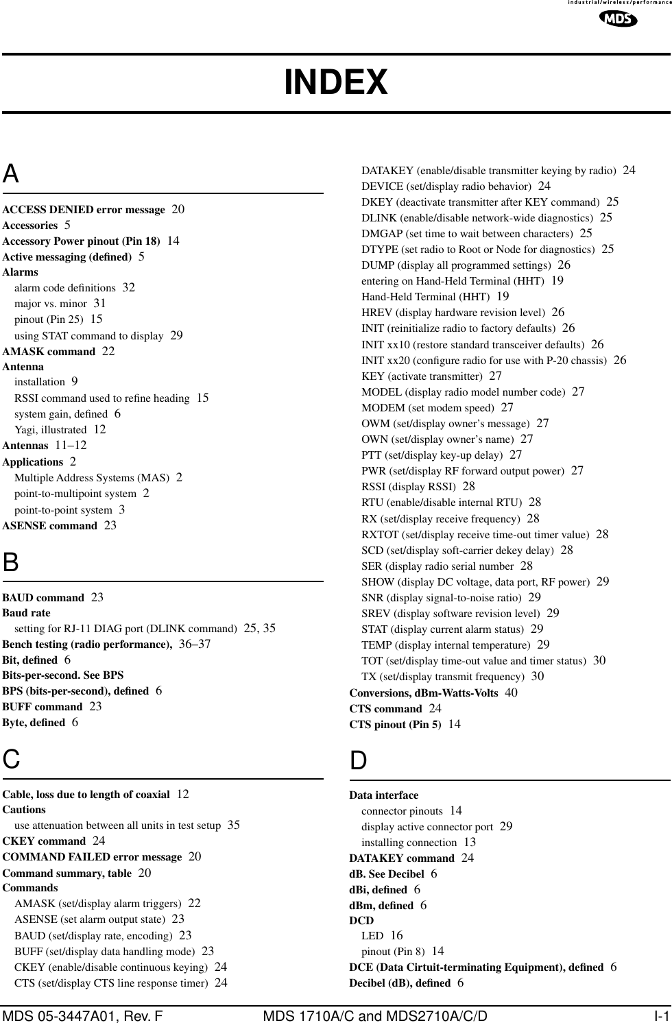
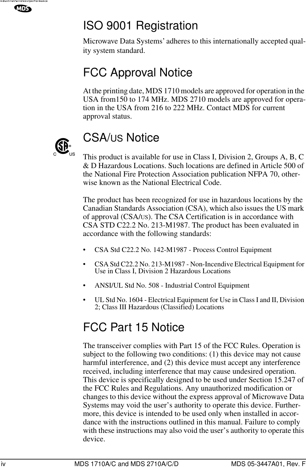
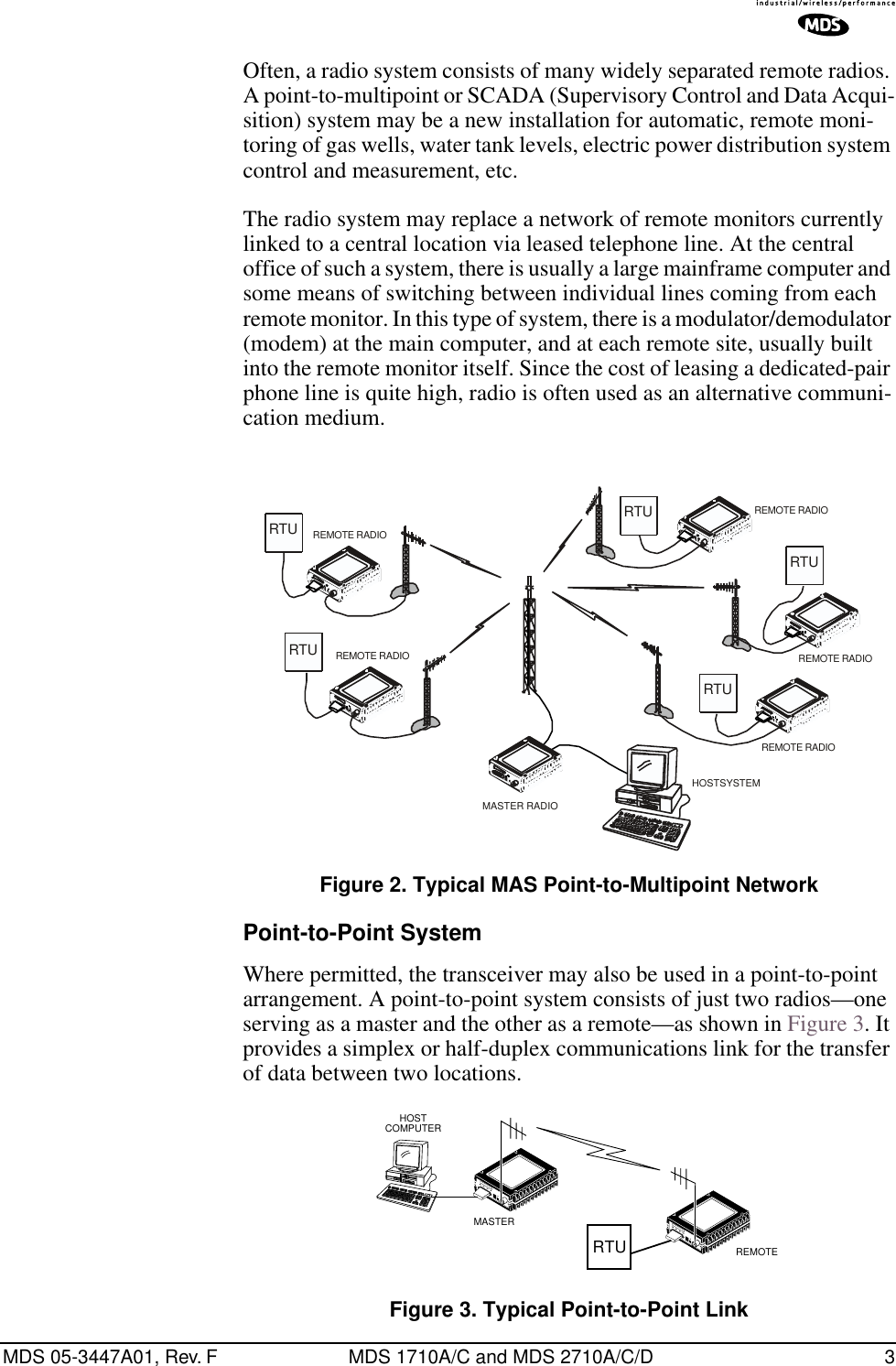
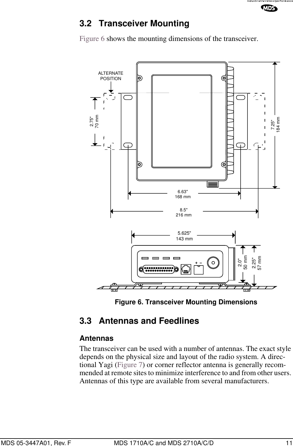
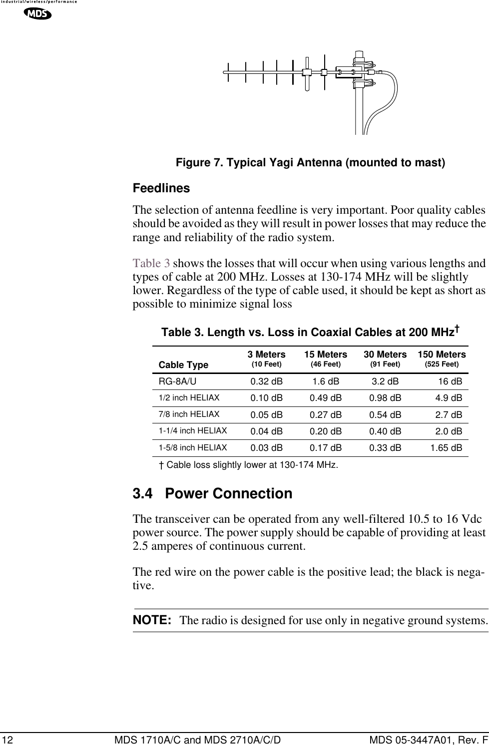
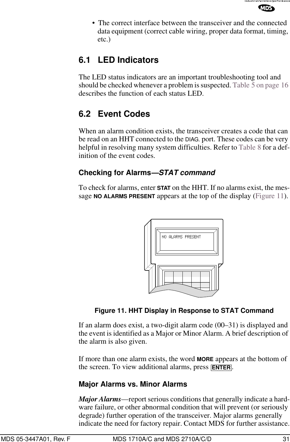
![MDS 05-3447A01, Rev. F MDS 1710A/C and MDS 2710A/C/D i TABLE OF CONTENTS 1.0 GENERAL.................................................................................... 1 1.1 Introduction ......................................................................................11.2 Differences Between Models ...........................................................21.3 Applications ......................................................................................2Point-to-Multipoint, Multiple Address Systems (MAS) ....................2Point-to-Point System .....................................................................3Continuously Keyed versus Switched Carrier Operation................4Single Frequency (Simplex) Operation...........................................41.4 Product Configurator Codes .............................................................41.5 Accessories ......................................................................................5 2.0 GLOSSARY OF TERMS.............................................................. 5 3.0 INSTALLATION............................................................................ 8 3.1 Installation Steps ..............................................................................93.2 Transceiver Mounting .....................................................................113.3 Antennas and Feedlines ................................................................11Feedlines ......................................................................................123.4 Power Connection ..........................................................................123.5 Data Interface Connections ............................................................133.6 Using the Radio’s Sleep Mode .......................................................13Sleep Mode Example ...................................................................13 4.0 OPERATION.............................................................................. 15 4.1 LED Indicators ................................................................................164.2 RSSI Measurement ........................................................................16 5.0 TRANSCEIVER PROGRAMMING ............................................ 17 5.1 Hand-Held Terminal Connection & Startup ....................................175.2 Hand-Held Terminal Setup .............................................................185.3 Keyboard Commands .....................................................................19Entering Commands.....................................................................19Error Messages ............................................................................195.4 Detailed Command Descriptions ...................................................22AMASK [0000 0000–FFFF FFFF] ................................................22ASENSE [HI/LO]...........................................................................23BAUD [xxxxx abc] .........................................................................23BUFF [ON, OFF]...........................................................................23CKEY [ON–OFF] ..........................................................................24CTS [0–255] .................................................................................24DATAKEY [ON, OFF] ....................................................................24DEVICE [DCE, CTS KEY] ............................................................24DKEY............................................................................................25](https://usermanual.wiki/GE-MDS/DS-2710AC/User-Guide-479003-Page-3.png)
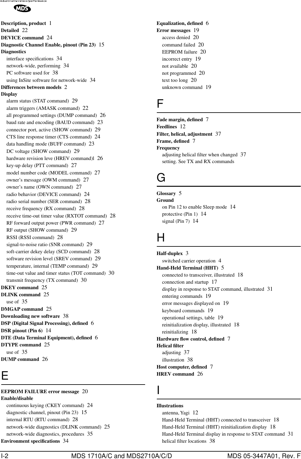
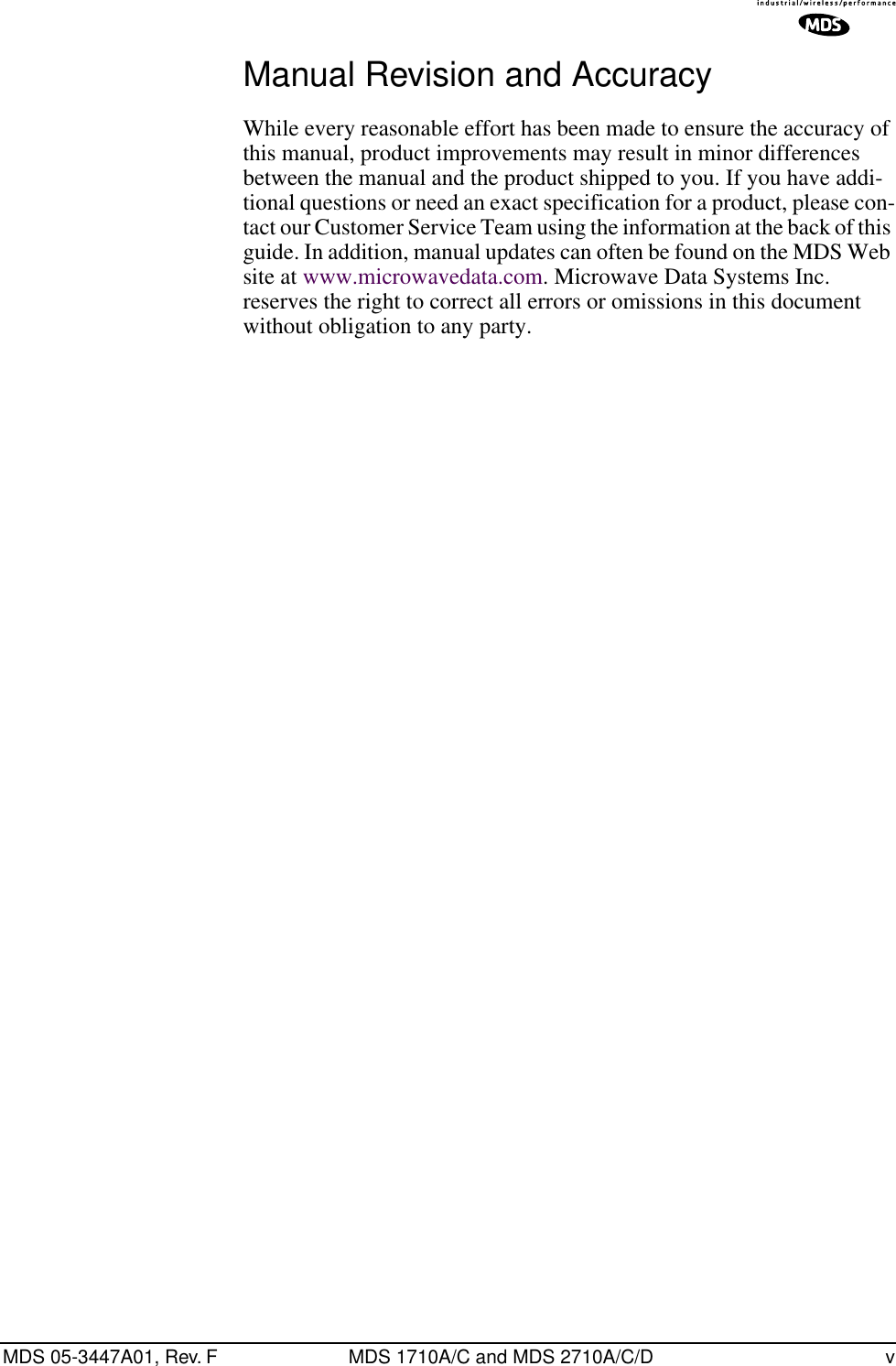
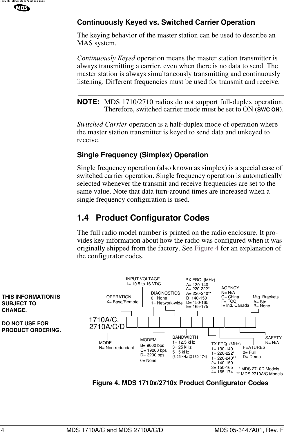
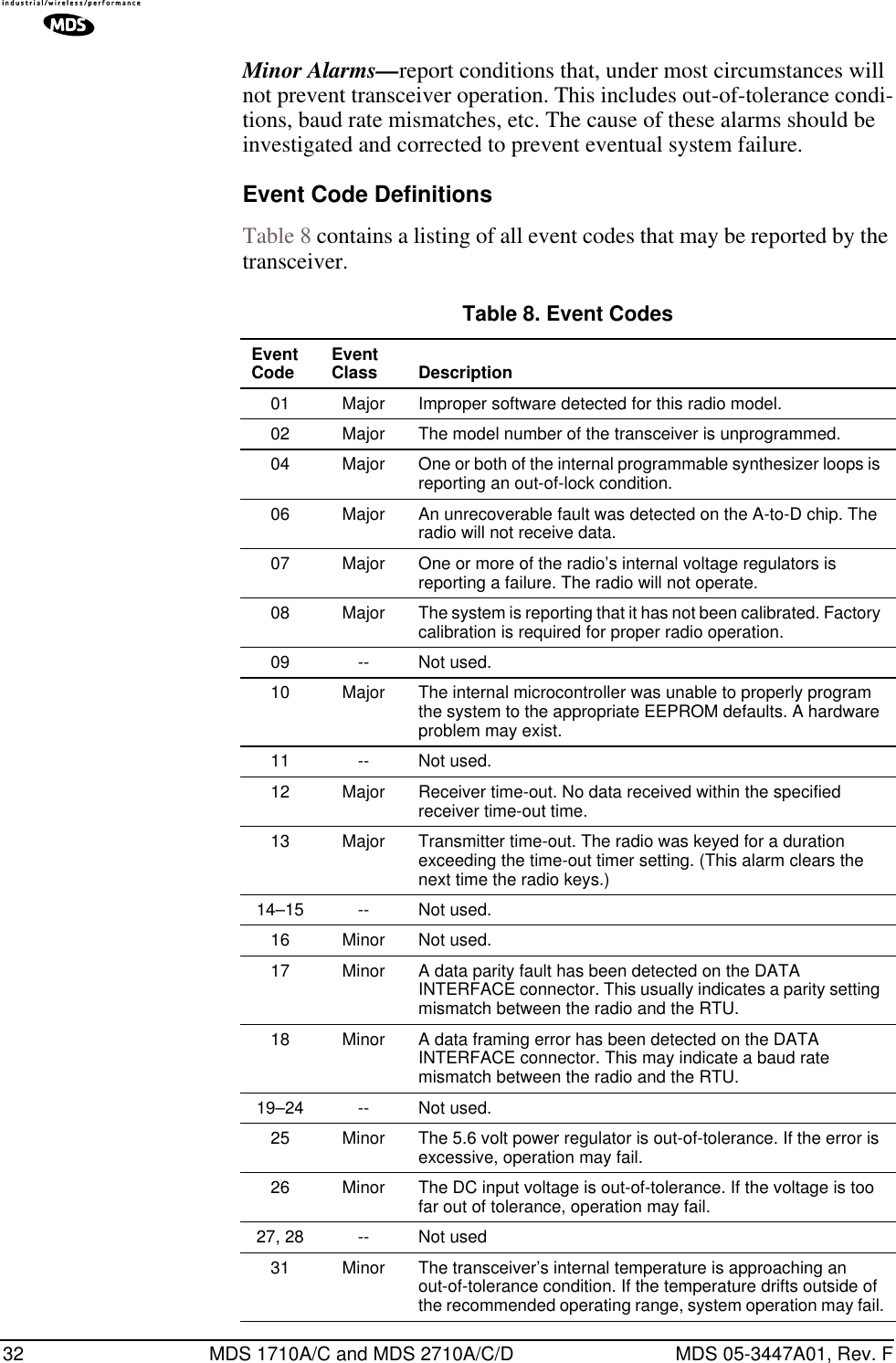
![ii MDS 1710A/C and MDS 2710A/C/D MDS 05-3447A01, Rev. FDLINK [ON/OFF/xxxx] ..................................................................25DMGAP [xx]..................................................................................25DTYPE [NODE/ROOT] .................................................................25DUMP ...........................................................................................26HREV............................................................................................26INIT...............................................................................................26INIT [2710]....................................................................................26INIT [2720]....................................................................................26KEY ..............................................................................................27MODEL.........................................................................................27MODEM [xxxx, NONE] .................................................................27OWM [XXX...] ...............................................................................27OWN [XXX...]................................................................................27PTT [0–255]..................................................................................27PWR [20–37] ................................................................................27RSSI .............................................................................................28RTU [ON/OFF/0-80]......................................................................28RX [xxx.xxxxx] ..............................................................................28RXTOT [NONE, 1-255] .................................................................28SCD [0-255]..................................................................................28SER ..............................................................................................28SHOW [DC, PORT, PWR].............................................................29SNR ..............................................................................................29SREV............................................................................................29STAT .............................................................................................29TEMP............................................................................................29TOT [1-255, ON, OFF]..................................................................30TX [xxx.xxxxx]...............................................................................30UNIT [10000...65000] ...................................................................30 6.0 TROUBLESHOOTING............................................................... 30 6.1 LED Indicators ................................................................................316.2 Event Codes ...................................................................................31Checking for Alarms—STAT command.........................................31Major Alarms vs. Minor Alarms.....................................................31Event Code Definitions .................................................................32 7.0 TECHNICAL REFERENCE ....................................................... 33 7.1 Transceiver Specifications ..............................................................337.2 Performing Network-Wide Remote Diagnostics .............................347.3 Bench Testing Setup ......................................................................367.4 Helical Filter Adjustment ................................................................377.5 Upgrading the Radio’s Software .....................................................38Using Radio Software Upgrade Diskette ......................................38Using Radio Configuration Software.............................................397.6 dBm-Watts-Volts Conversion Chart ................................................40](https://usermanual.wiki/GE-MDS/DS-2710AC/User-Guide-479003-Page-4.png)

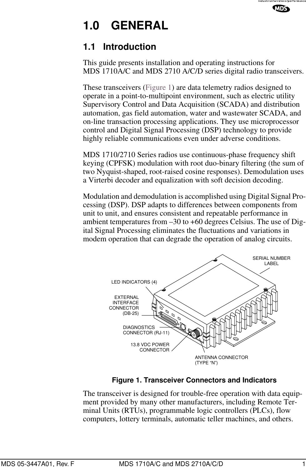
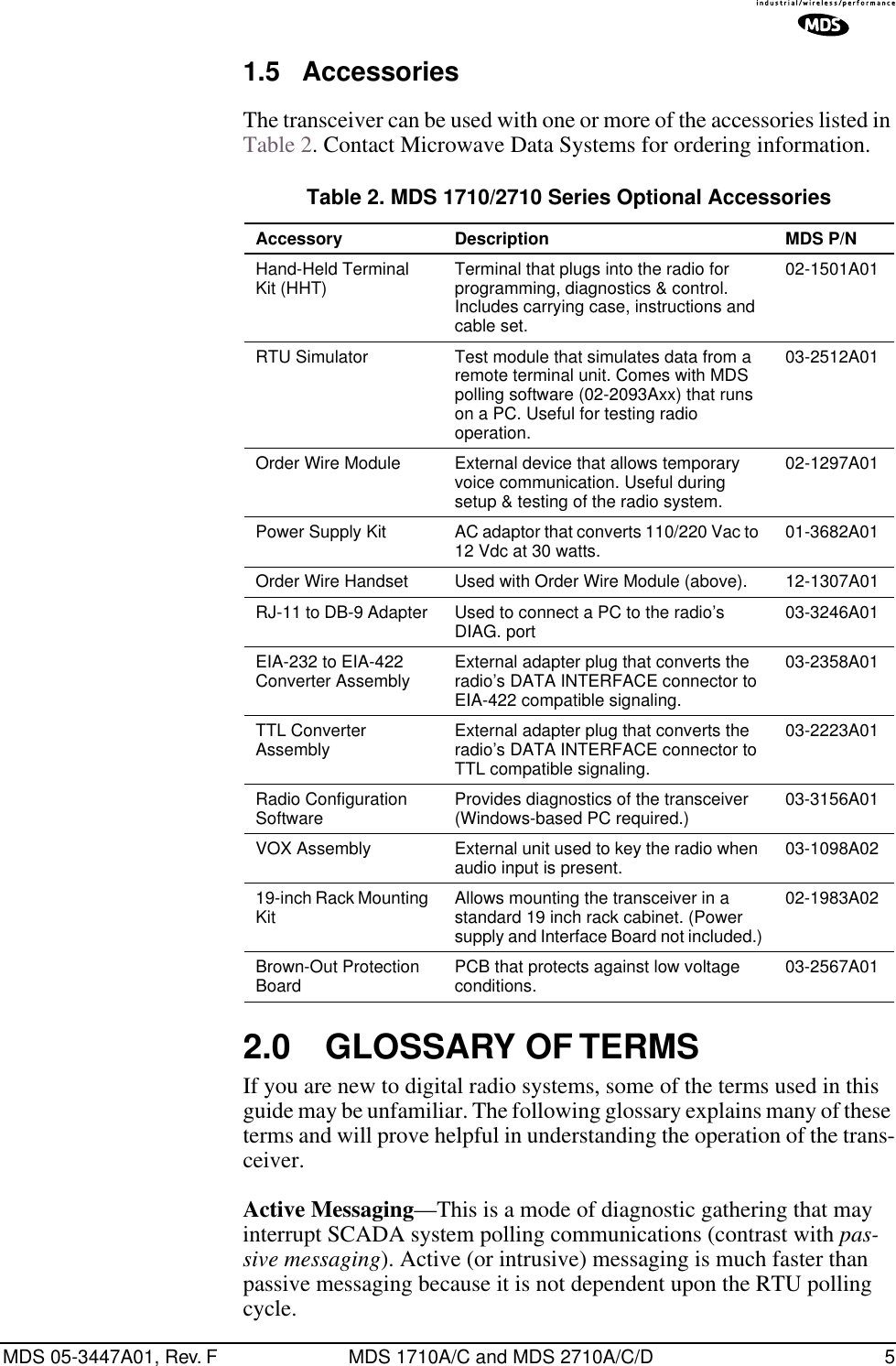
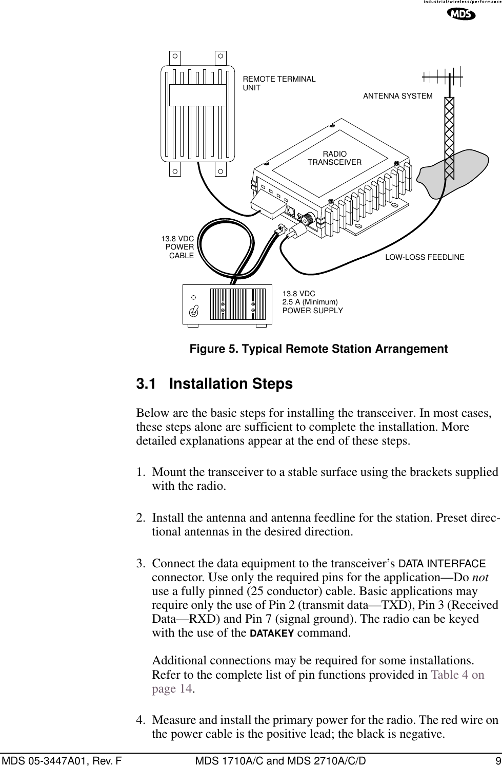
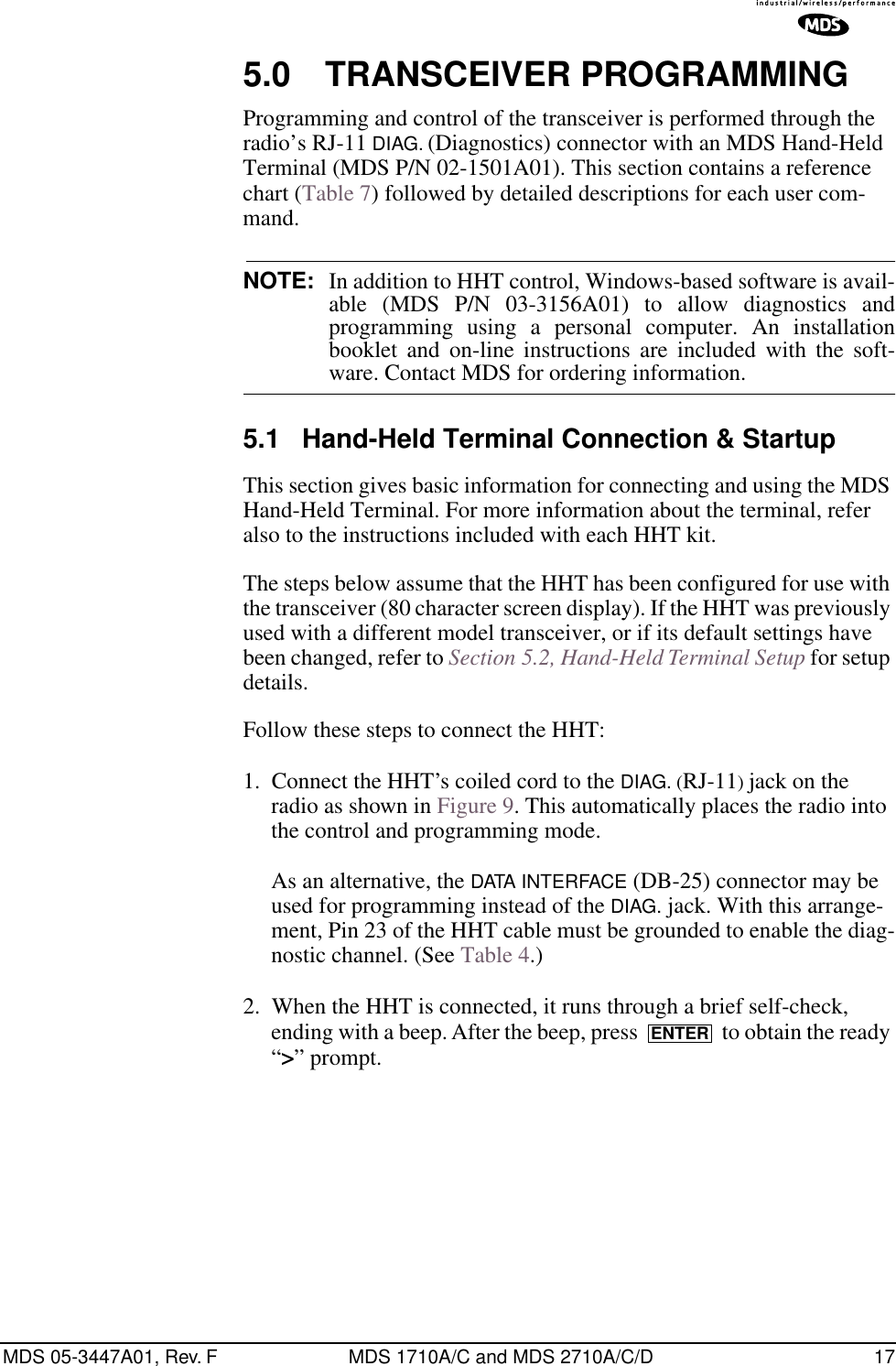
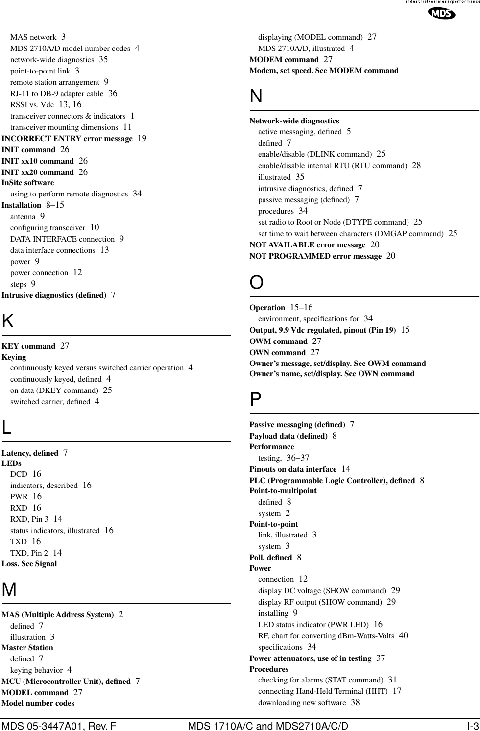
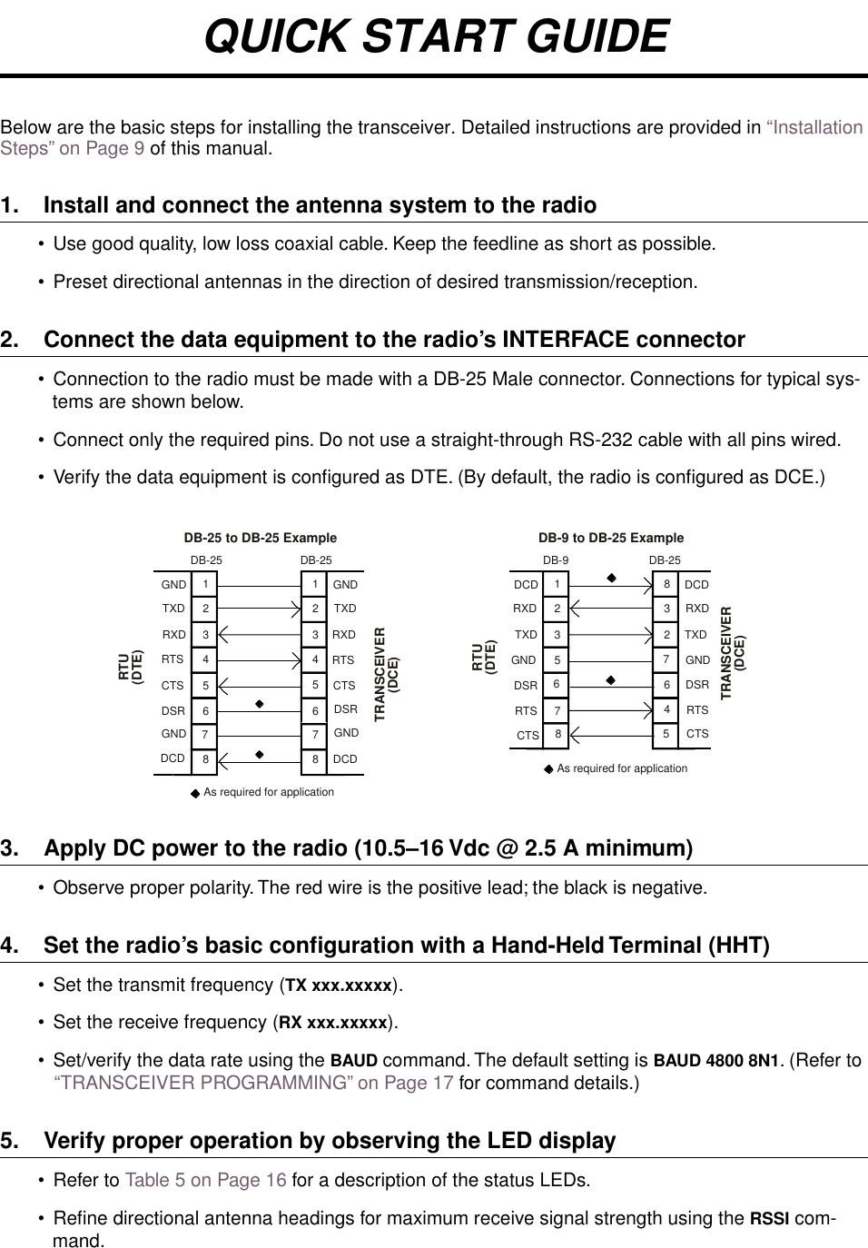
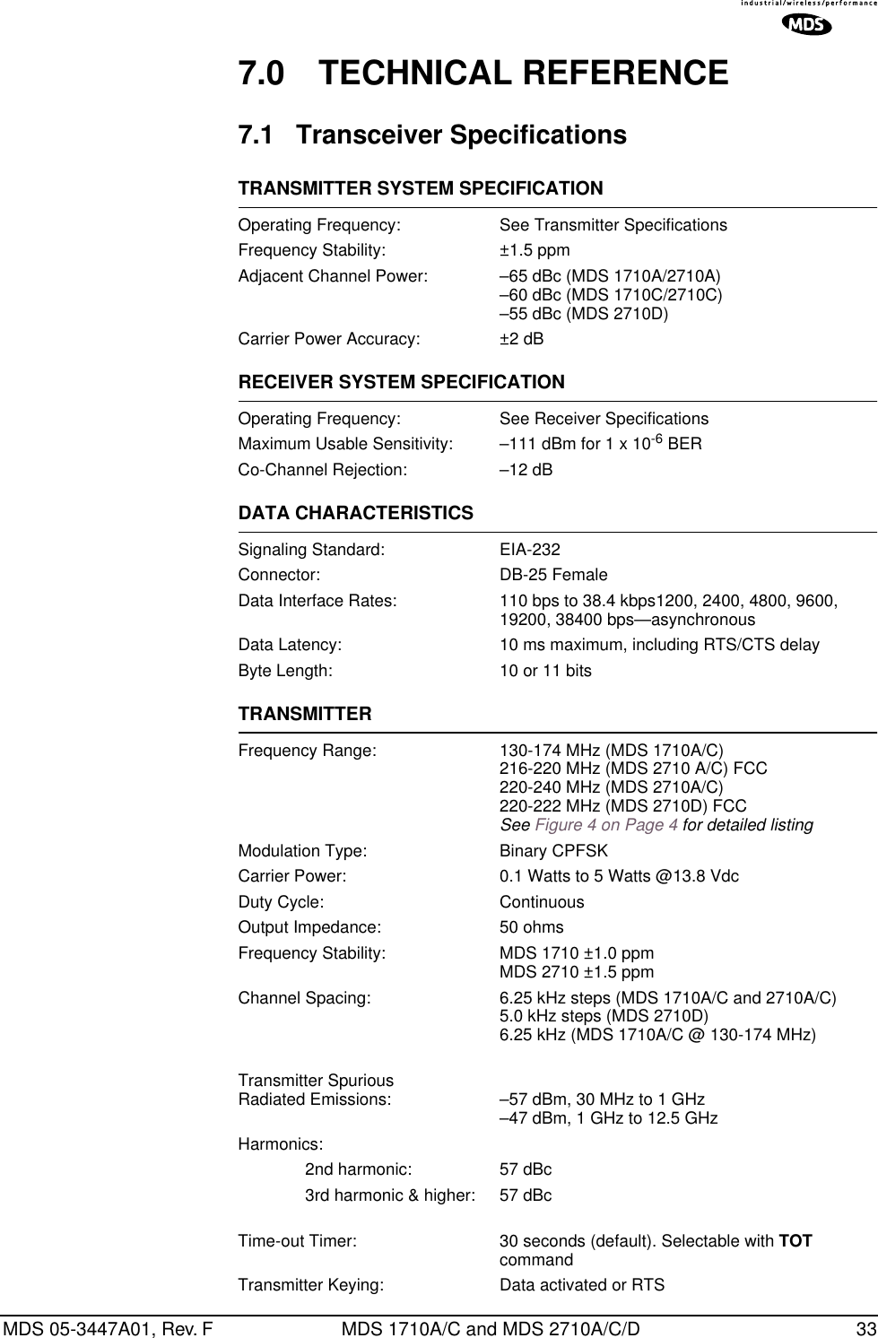
![MDS 05-3447A01, Rev. F MDS 1710A/C and MDS 2710A/C/D 193. Set up the HHT as listed in Table 6.5.3 Keyboard CommandsTable 7 is a reference chart of software commands for the transceiver. Programmable information is shown in brackets [ ] following the com-mand name. See Section 5.4, Detailed Command Descriptions for detailed command descriptions.Entering CommandsTo enter a command, type the command, followed by an key-stroke. For programming commands, the command is followed by and the appropriate information or values, then .Here are some additional points to remember when using the HHT:• Use the key to access numbers; press again to return to letter mode.• Use the key to edit information or commands entries.• The flashing square cursor ( ) indicates that letter mode is selected.• The flashing superscript rectangular cursor ( ) indicates that number mode is selected.Error MessagesListed below are some possible error messages that may be encountered when using the HHT:UNKNOWN COMMAND—The command was not recognized. Refer to the command description for command usage information.INCORRECT ENTRY—The command format or its associated values were not valid. Refer to the command description for command usage infor-mation.Table 6. HHT Operational Settings Parameter Setting Parameter SettingRe-init HT NO Scroll On 33rdBaud Rate 9600 Cursor ONComm bits 8,1,n CRLF for CR OFFParity Error OFF Self Test FASTKey Repeat OFF Key Beep ONEcho OFF Screen Size 80Shift Keys YES Menu Mode LONGCtl Chars PROCSENTERSPACE ENTERSHIFTESC/BKSP](https://usermanual.wiki/GE-MDS/DS-2710AC/User-Guide-479003-Page-27.png)
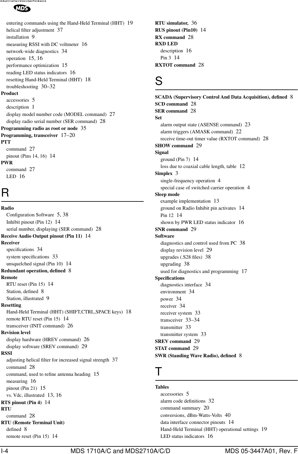
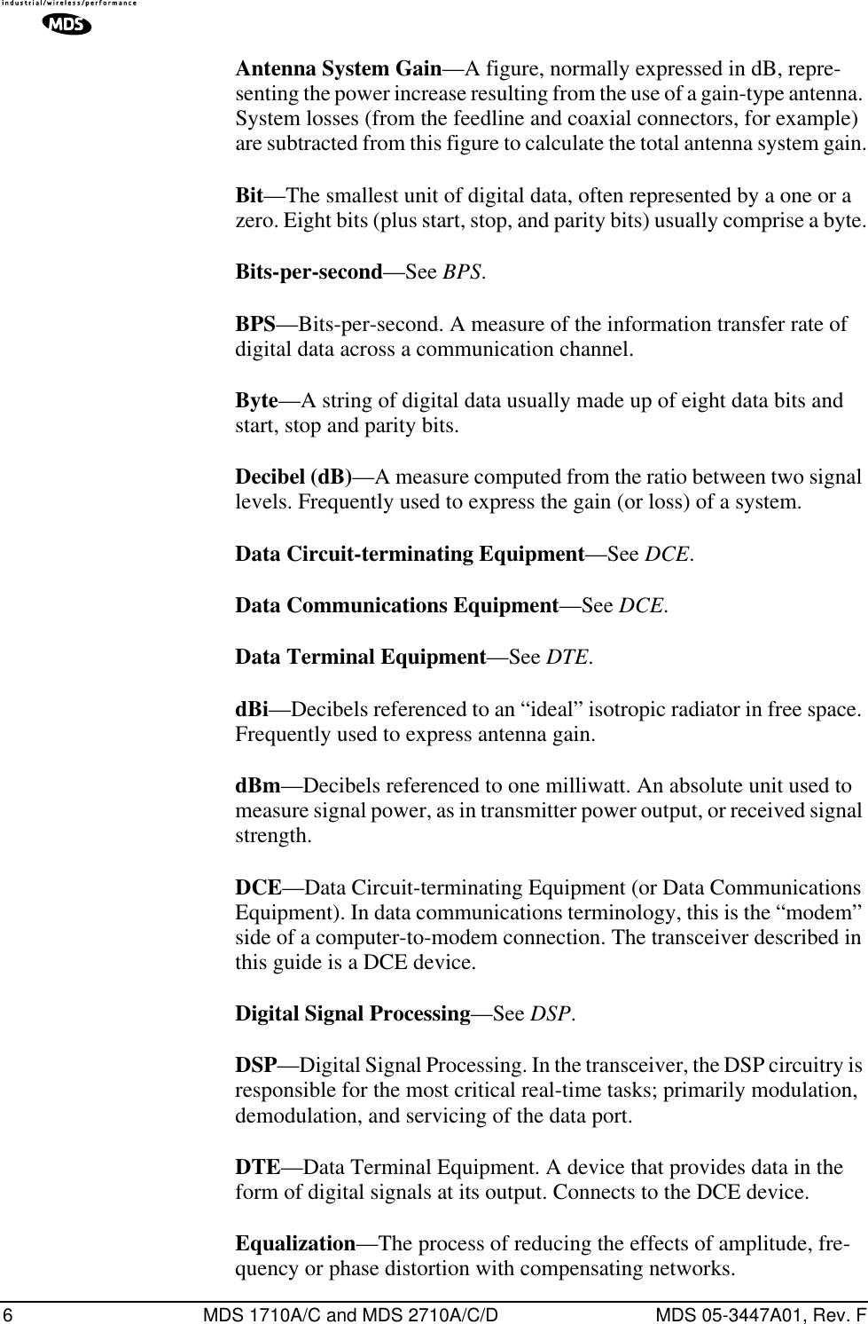
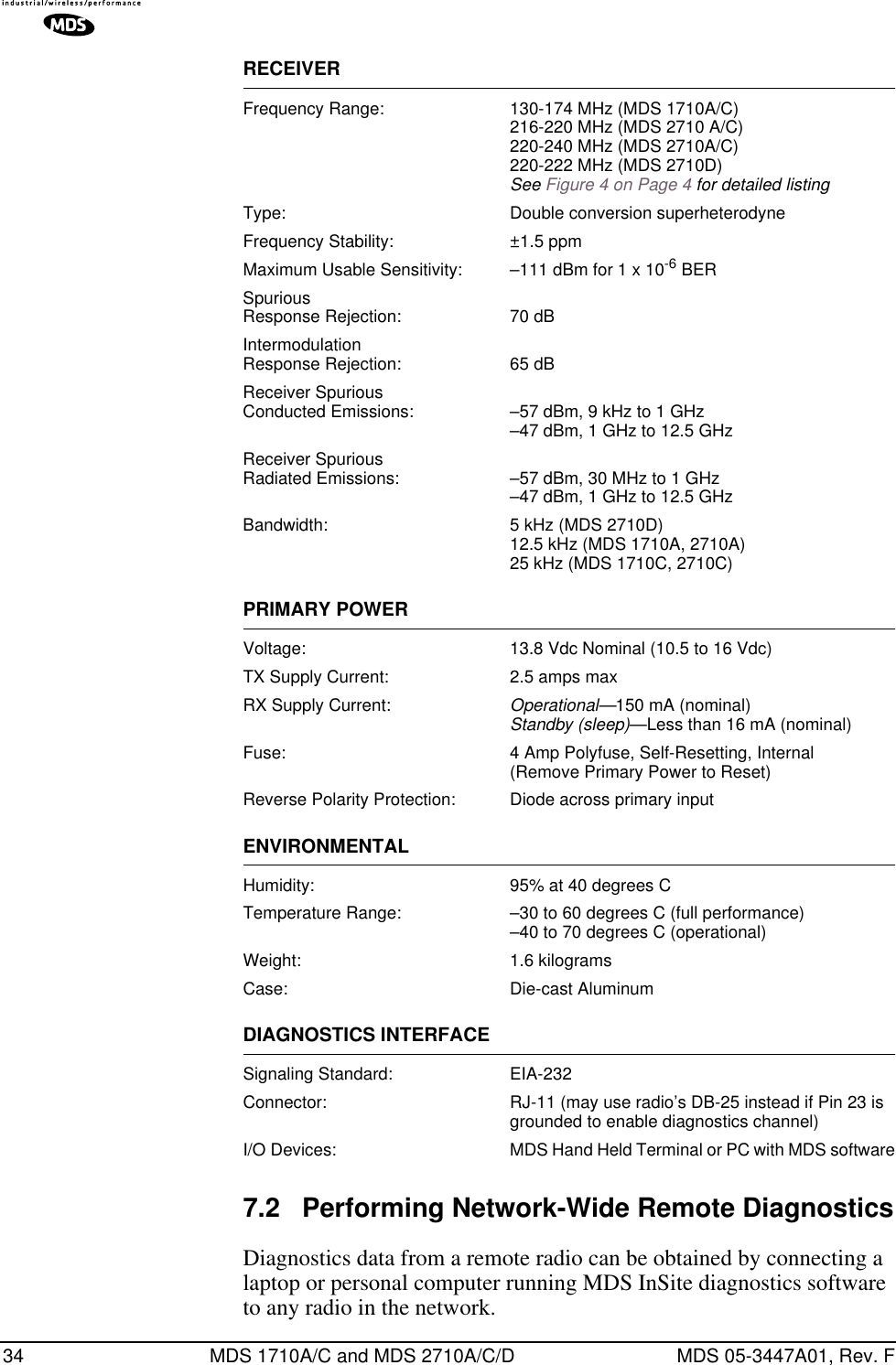
![20 MDS 1710A/C and MDS 2710A/C/D MDS 05-3447A01, Rev. FCOMMAND FAILED—The command was unable to successfully complete. This may indicate an internal software problem.NOT PROGRAMMED—Software was unable to program the internal radio memory or the requested item was not programmed.This is a serious internal radio error. Contact MDS for assistance.TEXT TOO LONG—Response to OWN or OWM command when too many characters have been entered. Refer to the command description for command usage information.NOT AVAILABLE—The entered command or parameter was valid, but it referred to a currently unavailable choice. Refer to the command description for command usage information.ACCESS DENIED—The command is unavailable to the user. Refer to the command descriptions for command information.EEPROM FAILURE— The INIT command was unable to write to EEPROM. This is a serious internal radio error. Contact MDS for assistance.Table 7. Command summary Command name Function AMASK [0000 0000–FFFF FFFF]Details page 22Set or display hex code identifying which events trigger an alarm. ASENSE [HI/LO]Details page 23 Set or display the state of the alarm output signal to ACTIVE HI or ACTIVE LO. BAUD [xxxxx abc]Details page 23 Set or display the DATA INTERFACE data rate and control bits. BUFF [ON, OFF]Details page 23 Enables or disables the internal radio data buffer. CTS [0–255]Details page 24 Set or display the Clear-to-Send delay in seconds. CKEY [ON–OFF]Details page 24 Enables or disables the continuously keyed mode. Note: Remotes cannot receive when keyed. DATAKEY [ON, OFF]Details page 24 Toggles between key-on-data and key-on-RTS. DKEYDetails page 25 Dekey the radio (transmitter OFF). This is generally a radio test command. DLINK [ON/OFF/xxxx]Details page 25 Configures local diagnostic link protocol. DMGAP [xx]Details page 25 (Diagnostics) Sets the amount of time to wait after the receipt of a character before interpreting the next received character as the start of a new message.](https://usermanual.wiki/GE-MDS/DS-2710AC/User-Guide-479003-Page-28.png)
![MDS 05-3447A01, Rev. F MDS 1710A/C and MDS 2710A/C/D 21 DTYPE [NODE/ROOT]Details page 25 (Diagnostics) Sets up a radio as a Root or Node radio. Associated commands are GATE and PEER. (See MDS’ Network-Wide Diagnostics System Handbook (MDS P/N 05-3467A01) for details.) DUMPDetails page 26 Display all programmable settings. HREVDetails page 26 Display the Hardware Revision level, if programmed. INITDetails page 26 Set radio parameters to factory defaults. INIT [2710]Details page 26 Restores certain transceiver defaults before using the INIT xx20 command. INIT [2720]Details page 26 Configure radio for use with an MDS model P-20 chassis. KEYDetails page 27 Key the radio (transmitter ON). This is generally used for radio testing. MODELDetails page 27 Display the model number of the radio. MODEM [xxxx, NONE]Details page 27 Set the modem characteristics of the radio. OWM [XXX...]Details page 27 Set or display the owner’s message. OWN [XXX...]Details page 27 Set or display the owner’s name. PTT [0–255]Details page 27 Set or display the Push-to-Talk delay in milliseconds. PWR [20–37]Details page 27 Set or display the transmit power setting. RSSIDetails page 28 Display the Received Signal Strength Indication. RTU [ON/OFF/0-80]Details page 28 Enables or disables the radio’s internal RTU simulator and sets the RTU address. RX [xxx.xxxxx]Details page 28 Set or display receiver frequency. RXTOT [NONE, 1-255]Details page 28 Set or display the value of the receive time-out timer. SCD [0-255]Details page 28 Set or display the Soft-carrier Dekey delay in milliseconds. SERDetails page 28 Display the radio serial number. SHOW [DC, PORT, PWR]Details page 29 Display the DC voltages, diagnostics port, and transmit power level. SREVDetails page 29 Display the Software Revision Level. STATDetails page 29 Display radio status and alarms.Table 7. Command summary (Continued)Command name Function](https://usermanual.wiki/GE-MDS/DS-2710AC/User-Guide-479003-Page-29.png)
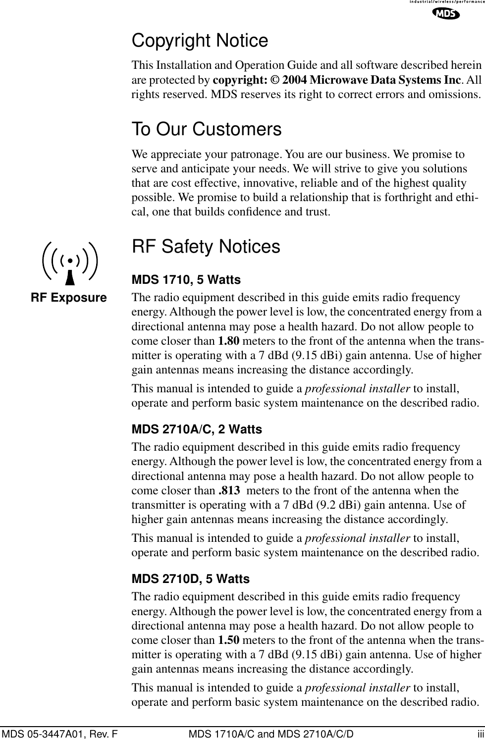
![22 MDS 1710A/C and MDS 2710A/C/D MDS 05-3447A01, Rev. F5.4 Detailed Command DescriptionsThe only critical commands for most applications are transmit and receive frequencies (RX xxx.xxxxx, TX xxx.xxxxx). However, proper use of the additional commands allows you to tailor the transceiver for a spe-cific use, or conduct basic diagnostics on the radio. This section gives more detailed information for the user commands previously listed in Table 7.In many cases, the commands shown here can be used in two ways. First, you can type only the command name to view the currently pro-grammed data. Secondly, you can set or change the existing data by typing the command, followed by a space, and then the desired entry. In the list below, allowable programming variables, if any, are shown in brackets following the command name.AMASK [0000 0000–FFFF FFFF]The AMASK (alarm mask) command displays or sets which events cause the alarm output signal to be active. Normally, the mask is FFFF FFFF, meaning that any of the 32 possible events will activate the alarm output signal. No special configuration is required for typical applications.Entering the AMASK command alone displays the current setting of alarm events in hexadecimal format.Entering the AMASK command followed by an eight-digit hexadecimal number reprograms the specified events to trigger an alarm.The eight-digit hexadecimal number used as the command parameter is used to classify up to 32 events as alarm triggers for the alarm output status line. (See Table 8 on page 32 for a list of event codes.) The hex value for the mask corresponds to the hex value for the STAT command (see the STAT command description). TEMPDetails page 29 Display the internal temperature of the radio in degrees Celsius. TOT [1-255, ON, OFF]Details page 30 Set or display the Time-out Timer delay in seconds. TX [xxx.xxxxx]Details page 30 Set or display the transmit frequency. UNIT [10000...65000]Details page 30 Set or display the transceiver’s unit address.Table 7. Command summary (Continued)Command name Function](https://usermanual.wiki/GE-MDS/DS-2710AC/User-Guide-479003-Page-30.png)
![MDS 05-3447A01, Rev. F MDS 1710A/C and MDS 2710A/C/D 23Each bit that is a ‘1’ identifies an associated alarm condition that can trigger the alarm output status line. Each bit that is a ‘0’ treats the asso-ciated alarm as irrelevant when deciding whether or not to assert the alarm output status line. For more information on tailoring the alarm response, contact the MDS Technical Services Department.ASENSE [HI/LO]The ASENSE command sets or displays the sense of the alarm output at Pin 25 of the DATA INTERFACE connector.Entering the ASENSE command alone shows whether the alarm output is active high or low. Entering the ASENSE command followed by HI or LO resets the alarm output to active high or low.BAUD [xxxxx abc]This command sets (or displays) the communication attributes for the DATA INTERFACE port. It has no effect on the RJ-11 DIAG. port.The first parameter (xxxxx) is baud rate. Baud rate is specified in bits-per-second (bps) and must be one of the following speeds: 110, 300, 1200, 2400, 4800, 9600, 19200, or 38400.The second parameter of the BAUD command (abc) is a three-character block indicating how the data is encoded:a = Data bits (7 or 8)b = Parity (N for None, O for Odd, E for Even)c = Stop bits (1 or 2)The factory default setting is 4800 baud, 8 data bits, no parity, 1 stop bit (Example: 4800 8N1).NOTE: 7N1, 8O2, and 8E2 are invalid communication settings and arenot supported by the transceiver.BUFF [ON, OFF]This command sets or displays the received data handling mode of the radio. The command parameter is either ON or OFF. The default is ON. The setting of this parameter affects the timing of how received RF data is sent out the INTERFACE connector. Outgoing (transmitted) data is not affected by this setting.If data buffering is OFF, the radio operates with the lowest possible average latency. Data bytes are thus sent out the INTERFACE port as soon as an incoming RF data frame is disassembled. Average and typical latency will both be below 10 ms, but idle character gaps may be intro-duced into the outgoing data flow.](https://usermanual.wiki/GE-MDS/DS-2710AC/User-Guide-479003-Page-31.png)
![24 MDS 1710A/C and MDS 2710A/C/D MDS 05-3447A01, Rev. FIf data buffering is ON, the radio operates in seamless mode. Data bytes will be sent over the air as quickly as possible, but the receiver buffers (stores) the data until enough bytes have arrived to cover worst-case gaps in transmission. This mode of operation is required for protocols such as MODBUS™ that do not allow gaps in their data transmission.Note that seamless mode (BUFF ON) is intended only for applications where the transmitter’s baud rate is greater than or equal to the receiver’s baud rate. Adherence to this rule is left up to the user.CKEY [ON–OFF]The CKEY command enables or disables the continuously-keyed func-tion of the radio. When CKEY is set to ON, the radio is continuously keyed.CTS [0–255]The CTS (clear-to-send) command selects or displays the timer value associated with the CTS line response. The command parameter ranges from 0 to 255 milliseconds.For DCE operation, the timer specifies how long to wait after the RTS line goes high, before the radio asserts CTS and the DTE can transmit the data. A CTS value of zero keys the radio and asserts the CTS line immediately after the RTS line goes high.For CTS Key operation (see DEVICE command), the timer specifies how long to wait after asserting the CTS, before sending data out the DATA INTERFACE port. A timer value of zero means that data will be sent out the data port without imposing a key-up delay. (Other delays may be present based on selected radio operating parameters.)DATAKEY [ON, OFF]The DATAKEY command sets or displays the ability of the radio to key the transmitter as data is received at the DATA INTERFACE connector. Asserting RTS keys the radio regardless of this command setting.If DATAKEY is set to ON, the radio will key when a full data-character is received at the transceiver’s DATA INTERFACE connector. If DATAKEY is set to OFF, the radio needs to be keyed by asserting either the RTS or PTT signal or with the CKEY or KEY command.DEVICE [DCE, CTS KEY]The DEVICE command sets or displays the device behavior of the radio. The command parameter is either DCE or CTS KEY.](https://usermanual.wiki/GE-MDS/DS-2710AC/User-Guide-479003-Page-32.png)
![MDS 05-3447A01, Rev. F MDS 1710A/C and MDS 2710A/C/D 25The default selection is DCE. In this mode, CTS will go high following RTS, subject to the CTS programmable delay time. If the DATAKEY com-mand is set to ON, keying can be stimulated by the input of characters at the data port. Hardware flow control is implemented by signaling the CTS line if data arrives faster than it can be buffered and transmitted.If CTS KEY is selected, the radio is assumed to be controlling another radio. The RTS line is ignored and the CTS line is used as a keyline con-trol for the other radio. CTS is asserted immediately following the receipt of RF data, but data will not be sent out the DATA INTERFACE port until after the CTS programmable delay time has expired. (This gives the other radio time to key.)DKEYThis command deactivates the transmitter after it has been keyed with the KEY command.DLINK [ON/OFF/xxxx]This command is used to configure the local diagnostic link protocol used in network-wide diagnostics.Entering DLINK ON enables the diagnostic link. Entering DLINK OFF dis-ables the diagnostic link.To change the diagnostic link, enter DLINK followed by one of the fol-lowing baud rates: 1200, 2400, 4800, 9600, 19200 (default).DMGAP [xx]The DMGAP command sets the amount of time in milliseconds to wait after the receipt of a character before interpreting the next received char-acter as the start of a new message. When data port baud rates are slow, the gap between characters within a poll may be so long that the radio interprets the next character as the start of a new poll. When diagnostics is being performed using passive messaging (see Performing Net-work-Wide Remote Diagnostics on page 34), this command may be used to change this behavior.DTYPE [NODE/ROOT]This command establishes the local radio as a root radio or node radio for network-wide diagnostics. Entering DTYPE NODE configures the radio as a node radio. Entering DTYPE ROOT configures the radio as a root radio. Entering the DTYPE command alone displays the current setting. See “Performing Network-Wide Remote Diagnostics” on page 34. Two associated commands are GATE and PEER. See MDS’ Network-Wide Diagnostics System Handbook (MDS P/N 05-3467A01) for details.](https://usermanual.wiki/GE-MDS/DS-2710AC/User-Guide-479003-Page-33.png)
![26 MDS 1710A/C and MDS 2710A/C/D MDS 05-3447A01, Rev. FDUMPThis command displays all the programmed settings of the radio. The HHT display is too small to list all the command settings at one time. Therefore, this command is most useful if the command is issued from a computer or full-screen terminal.HREVThis command displays the transceiver’s hardware revision level if it has been programmed at the factory.INITThe INIT command is used to re-initialize the radio’s operating parame-ters to the factory defaults. This may be helpful when trying to resolve configuration problems that may have resulted from the entry of one or more improper command settings. Entry of this command allows you to get back to a known working state. The following changes to the radio are made when INIT is entered:•CTS is set to 0•DATAKEY is set to ON•DEVICE is set to DCE•PTT is set to 0•SCD is set to 0•TOT is set to 30 seconds and set to ON•PWR is set to +37 dBm (5 watts)All other commands stay at their previously established settings.INIT [2710]This command sets the transceiver for operation outside the MDS model P-20 chassis by setting the following parameters as shown.ASENSE ACTIVE HIAMASK FFFF FFFF (assert alarm output on all alarms)RXTOT NONE (receive time-out timer disabled)This command can be used subsequent to using the INIT 2720 command to restore the standard transceiver defaults.INIT [2720]This command sets the transceiver for operation inside the model P-20 chassis by setting the following parameters as shown.ASENSE ACTIVE LOAMASK FFFF 0000 (trigger on major alarms)RXTOT 20 (20 minute time-out timer)](https://usermanual.wiki/GE-MDS/DS-2710AC/User-Guide-479003-Page-34.png)
![MDS 05-3447A01, Rev. F MDS 1710A/C and MDS 2710A/C/D 27KEYThis command activates the transmitter. See also the DKEY command.MODELThis command displays the radio’s model number code.MODEM [xxxx, NONE]This command selects the radio’s modem characteristics. Enter 9600 or 3200 for digital operation, or enter NONE to select analog operation. For MDS 1710 digital operation the proper settings are 9600 for the MDS 2710A, 19200 for the MDS 1710C.For MDS 2710 operation, the proper settings are 3200 for the MDS 2710D, 9600 for the MDS 2710A, and 19200 for the MDS 2710C.OWM [XXX...]This is a command to display or program an owner’s message. To pro-gram the owner’s message, type OWM then the message, followed by .To display the owner’s message, type OWM then . The owner’s message appears on the display.OWN [XXX...]This is a command to display or program an owner’s name. To program the owner’s name, type OWN then the name, followed by .To display the owner’s name, type OWN then . The owner’s name appears on the display.PTT [0–255]This command sets or displays the key-up delay in milliseconds.This timer specifies how long to wait after the radio receives a key signal from either the PTT or RTS lines (on the DATA INTERFACE), before actu-ally keying the radio.PWR [20–37]NOTE: This function may not be available, depending on certificationrequirements in a particular country.This command displays or sets the desired RF forward output power set-ting of the radio. The PWR command parameter is specified in dBm and can range from 20 through 37. The default setting is 37 dBm (5 watts). To read the actual (measured) power output of the radio, use the SHOW PWR command. A dBm-to-watts conversion chart is provided in Section 7.6.ENTERENTERENTERENTER](https://usermanual.wiki/GE-MDS/DS-2710AC/User-Guide-479003-Page-35.png)
![28 MDS 1710A/C and MDS 2710A/C/D MDS 05-3447A01, Rev. FRSSIThis command continuously displays the radio’s Received Signal Strength Indication (RSSI) in dBm units, until you press the Enter key. Incoming signal strengths from –50 dBm to –120 dBm can be read.RTU [ON/OFF/0-80]This command re-enables or disables the radio’s internal RTU simu-lator, which runs with MDS’ proprietary polling programs (poll.exe and rsim.exe). The internal RTU simulator is available whenever a radio has diagnostics enabled. This command also sets the RTU address that the radio will respond to.The internal RTU can be used for testing system payload data or pseudo bit error rate testing. It can also be helpful in isolating a problem to either the external RTU or the radio.RX [xxx.xxxxx]This command selects or displays the radio’s receive frequency in MHz. The frequency step size is 6.25 kHz for the MDS 2710A/C and 5.0 kHz for the MDS 2710D.If the customer frequency has not been programmed at the factory, a default frequency will be programmed in the radio near the center of the frequency band.RXTOT [NONE, 1-255]The RXTOT command selects or displays the receive time-out timer value in minutes. This timer triggers an alarm (event 12) if data is not detected within the specified time.Entering the RXTOT command without a parameter displays the timer value in minutes. Entering the RXTOT command with a parameter ranging from 0 to 255 resets the timer in minutes. Entering the RXTOT command with the parameter NONE disables the timer.SCD [0-255]This command displays or changes the soft-carrier dekey delay in milli-seconds.This timer specifies how long to wait after the removal of the keying signal before actually releasing the transmitter. A value of 0 millisec-onds will unkey the transmitter immediately after the removal of the keying signal.SERThis command displays the radio’s serial number as recorded at the fac-tory.](https://usermanual.wiki/GE-MDS/DS-2710AC/User-Guide-479003-Page-36.png)
![MDS 05-3447A01, Rev. F MDS 1710A/C and MDS 2710A/C/D 29SHOW [DC, PORT, PWR]The SHOW command displays different types of information based on the command variables. The different parameters are:•DC—Display DC input/output voltages•PORT—Display the connector port (RJ-11 or DB-25) that is active for diagnostics and control.•PWR—Display RF power outputSNRThis command continuously displays the signal-to-noise ratio of the received signal expressed in dB, until you press the Enter key. As used in this guide, the signal-to-noise measurement is based upon the signal level following equalization, for received frames.The SNR is an indication of the received signal quality. The SNR indi-cation ranges from 10 dB to 33 dB. A value of 10 dB represents a very poor signal. A value of 24 dB represents a very good signal.When the SNR command is used, it causes the DIAG. port to enter an update mode, and the signal-to-noise ratio is updated and redisplayed every 2 seconds. The SNR continuously updates until the key is pressed.SREVThis command displays the software revision level of the transceiver firmware.STATThis command displays the current alarm status of the transceiver.If no alarms exist, the message NO ALARMS PRESENT appears at the top of the HHT display.If an alarm does exist, a two-digit code (00–31) is displayed and the alarm is identified as “Major” or “Minor.” A brief description of the alarm code is also given.If more than one alarm exists, the word MORE appears at the bottom of the screen and additional alarms are viewed by pressing the key. Detailed descriptions of event codes are provided in Table 8 on page 32.TEMPThis command displays the internal temperature of the transceiver in degrees Celsius.ENTERENTER](https://usermanual.wiki/GE-MDS/DS-2710AC/User-Guide-479003-Page-37.png)
![30 MDS 1710A/C and MDS 2710A/C/D MDS 05-3447A01, Rev. FTOT [1-255, ON, OFF]This command sets or displays the transmitter Time-out Timer value (1–255 seconds), as well as the timer status (ON or OFF). If the timer is on, and the radio remains keyed for a longer duration than the TOT value, the transmitter is automatically unkeyed.When this happens, the radio must be commanded back to an unkeyed state before a new keying command is accepted. The default timer value is 30 seconds.TX [xxx.xxxxx]This command selects or displays the radio’s transmit frequency in MHz. The frequency step size is 6.25 kHz for the MDS 2710A/C and 5.0 kHz for the MDS 2710D.If the customer frequency has not been programmed at the factory, a default frequency will be programmed in the radio near the center of the frequency band.UNIT [10000...65000]This command selects or displays the radio’s unit address. The factory default setting is the last five digits of the transceiver’s serial number. The unit address is used in network diagnostics. See MDS’ Net-work-Wide Diagnostics System Handbook (MDS P/N 05-3467A01) for more information.6.0 TROUBLESHOOTINGSuccessful troubleshooting of the radio system is not difficult, but it requires a logical approach. It is best to begin troubleshooting at the master station, as the rest of the system depends on the master for polling commands. If the master station has problems, the operation of the entire network can be compromised.It is good practice to start by checking the simple things. For proper operation, all radios in the network must meet these basic requirements:• Adequate and stable primary power. The radio contains an inter-nal self-resetting fuse (4A). Remove and re-apply primary power to reset.• Secure connections (RF, data and power)• An efficient and properly aligned antenna system with a good received signal strength (at least –90 dBm). It is possible for a system to operate with weaker signals, but reliability will be degraded. • Proper programming of the transceiver’s operating parameters (see Section 5.0, TRANSCEIVER PROGRAMMING).](https://usermanual.wiki/GE-MDS/DS-2710AC/User-Guide-479003-Page-38.png)
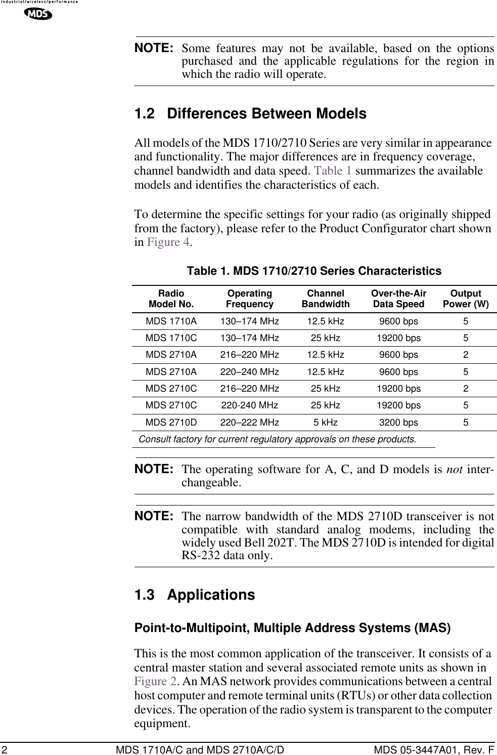
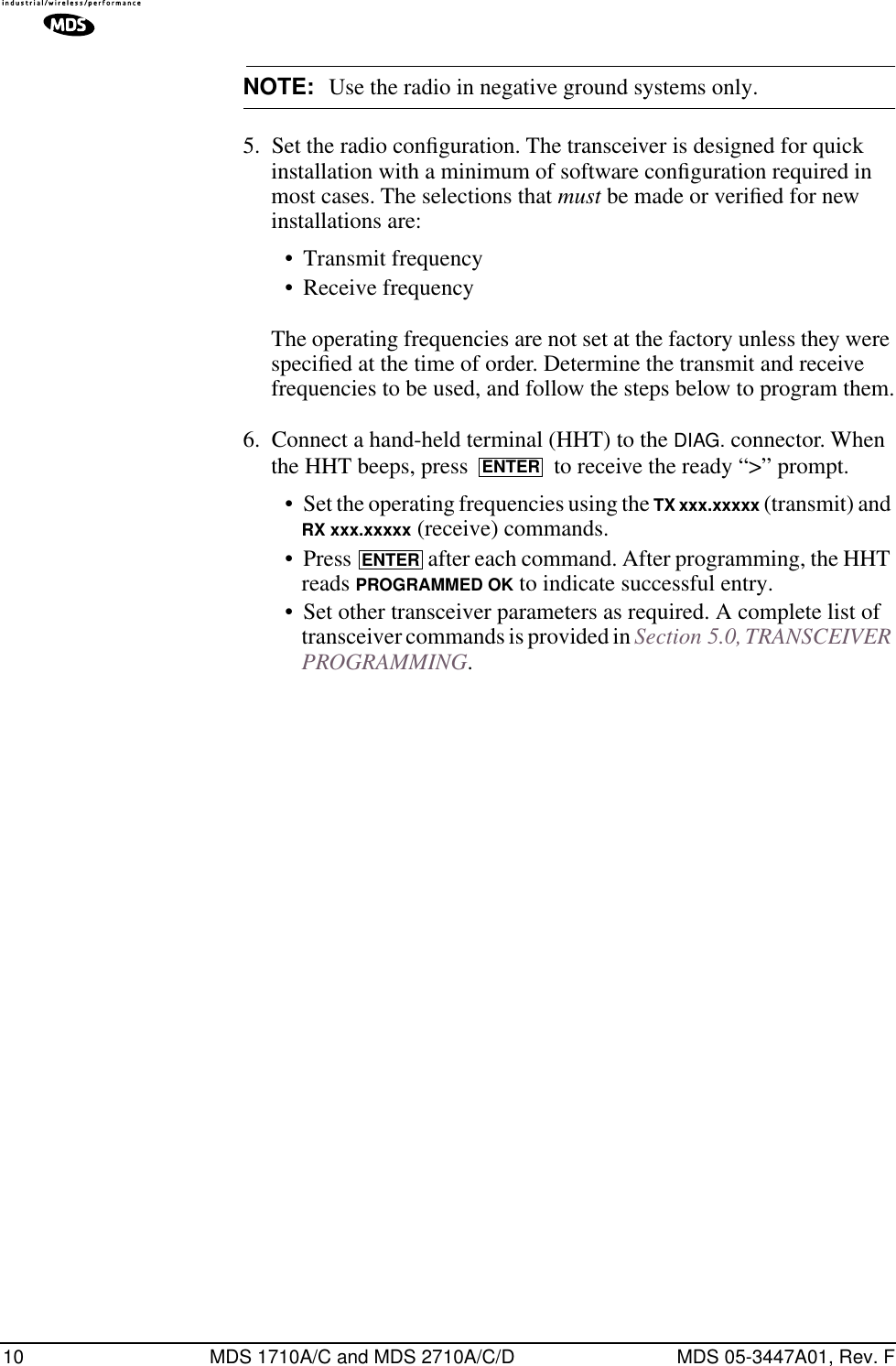
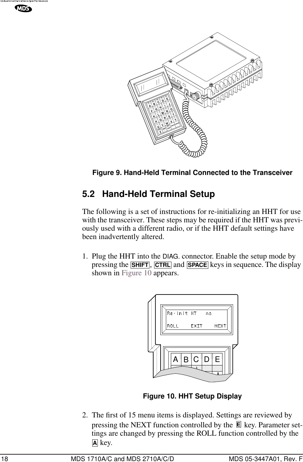
![MDS 05-3447A01, Rev. F MDS 1710A/C and MDS 2710A/C/D 35Figure 12 shows an example of a setup for performing network-wide remote diagnostics from both a Root (master station) location, and a Node (remote station) location.Invisible place holderFigure 12. Network-Wide Remote Diagnostics SetupIf a PC is connected to any radio in the network, intrusive polling (polling which briefly interrupts payload data transmission) can be per-formed. To perform diagnostics without interrupting payload data trans-mission, connect the PC to a radio defined as the “root” radio. A radio is defined as a root radio using the DTYPE ROOT command locally, at the radio.A complete explanation of remote diagnostics can be found in MDS’ Network-Wide Diagnostics System Handbook (MDS P/N 05-3467A01). See the Handbook for more information about the basic diagnostic procedures outlined below.1. Program one radio in the network as the root radio by entering the DTYPE ROOT command at the radio.2. At the root radio, use the DLINK ON and DLINK [baud rate] commands to configure the diagnostic link protocol on the RJ-11 port.RTURTURTUMASTER RADIODIAGNOSTICS COMPUTERRUNNING InSitePAYLOAD DATA(To SCADA Application)DIAGNOSTIC DATA(To InSite)HOSTCOMPUTERNODE(Supports IntrusiveDiagnostics Only)ROOT(Supports Intrusive orNon-Intrusive Diagnostics)](https://usermanual.wiki/GE-MDS/DS-2710AC/User-Guide-479003-Page-43.png)
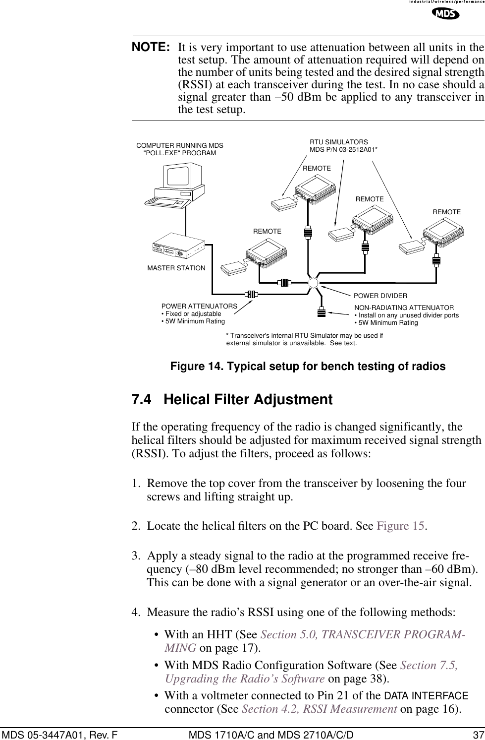
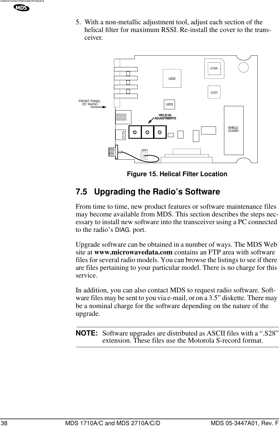
![36 MDS 1710A/C and MDS 2710A/C/D MDS 05-3447A01, Rev. F3. Program all other radios in the network as nodes by entering the DTYPE NODE command at each radio.4. Use the DLINK ON and DLINK [baud rate] commands to configure the diagnostic link protocol on the RJ-11 port of each node radio.5. Connect same-site radios using a null-modem cable at the radios’ diagnostic ports.6. Connect a PC on which MDS InSite software is installed to the root radio, or to one of the nodes, at the radio’s diagnostic port. (This PC may be the PC being used to collect payload data, as shown in Figure 12.)To connect a PC to the radio’s DIAG. port, an RJ-11 to DB-9 adapter (MDS P/N 03-3246A01) is required. If desired, an adapter cable may be constructed from scratch using the information shown in Figure 13.Invisible place holderFigure 13. RJ-11 to DB-9 Adapter Cable7. Launch the MDS InSite application at the PC. (See the MDS InSite User’s Guide for instructions.)7.3 Bench Testing SetupFigure 14 shows a sample test setup that can be used to verify the basic operation of transceivers in a shop setting. The test can be performed with any number of remote radios by using a power divider with the required number of output connections.The RTU simulator shown in the test setup (MDS Part No. 03-2512A01) is a microcontroller that emulates a remote terminal unit operating at 1200, 2400, 4800, or 9600 bps. Custom software is supplied with the RTU simulator that allows continuous polling of remote radios using an IBM-compatible personal computer. The software reports the number of polls sent, polls received, and the number of errors detected.As an alternative to using an external RTU simulator, the transceiver’s internal RTU simulator may be used (see RTU command in Table 7 on page 20). (This will not provide as conclusive a test as an external sim-ulator because it does not utilize the transceiver’s data connector.)RXDTXDGND235DB-9 FEMALE(TO COMPUTER)TXDRXDGND456RJ-11 PLUG(TO RADIO)RJ-11 PIN LAYOUT16](https://usermanual.wiki/GE-MDS/DS-2710AC/User-Guide-479003-Page-44.png)