GE MDS DS-5800-2 MDS 5800 II Digital Radio Transceiver User Manual Manual
GE MDS LLC MDS 5800 II Digital Radio Transceiver Manual
UserManual.wiki
>
GE MDS
>
DS-5800-2 User Manual
>
Manual
Contents
1.
Manual
2.
manual
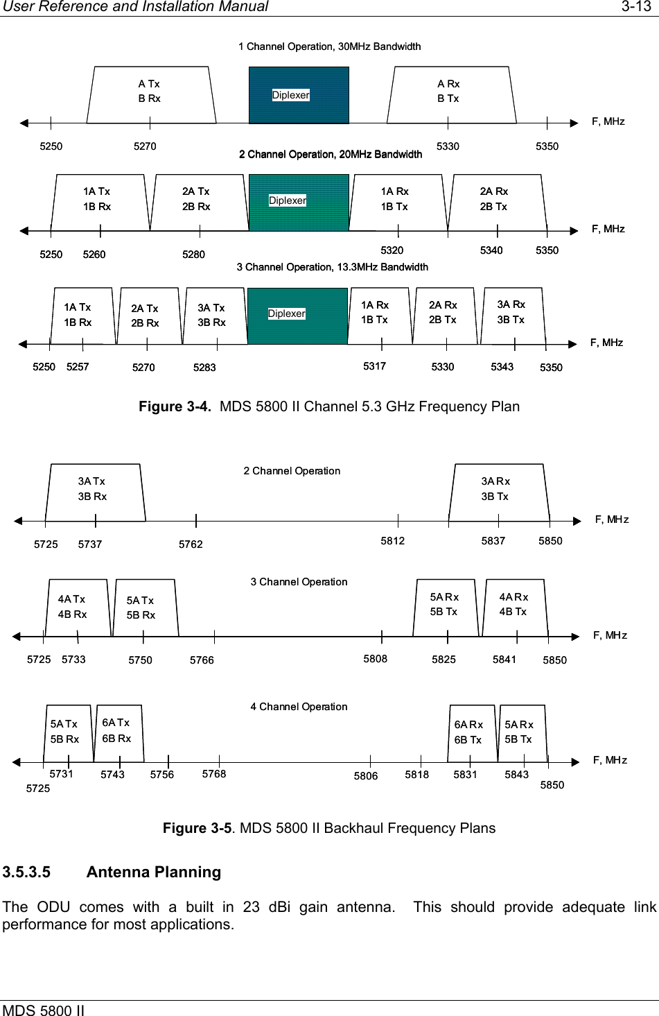
Manual
Navigation menu
Upload a User Manual
Namespaces
Wiki Guide
HTML
PDF
Info
Views
User Manual
Discussion / Help
Navigation