GE MDS DS-CW500 CarrierWave 500 User Manual
GE MDS LLC CarrierWave 500 Users Manual
UserManual.wiki
>
GE MDS
>
DS-CW500 User Manual
>
Manual revised
Contents
1.
Manual revised
2.
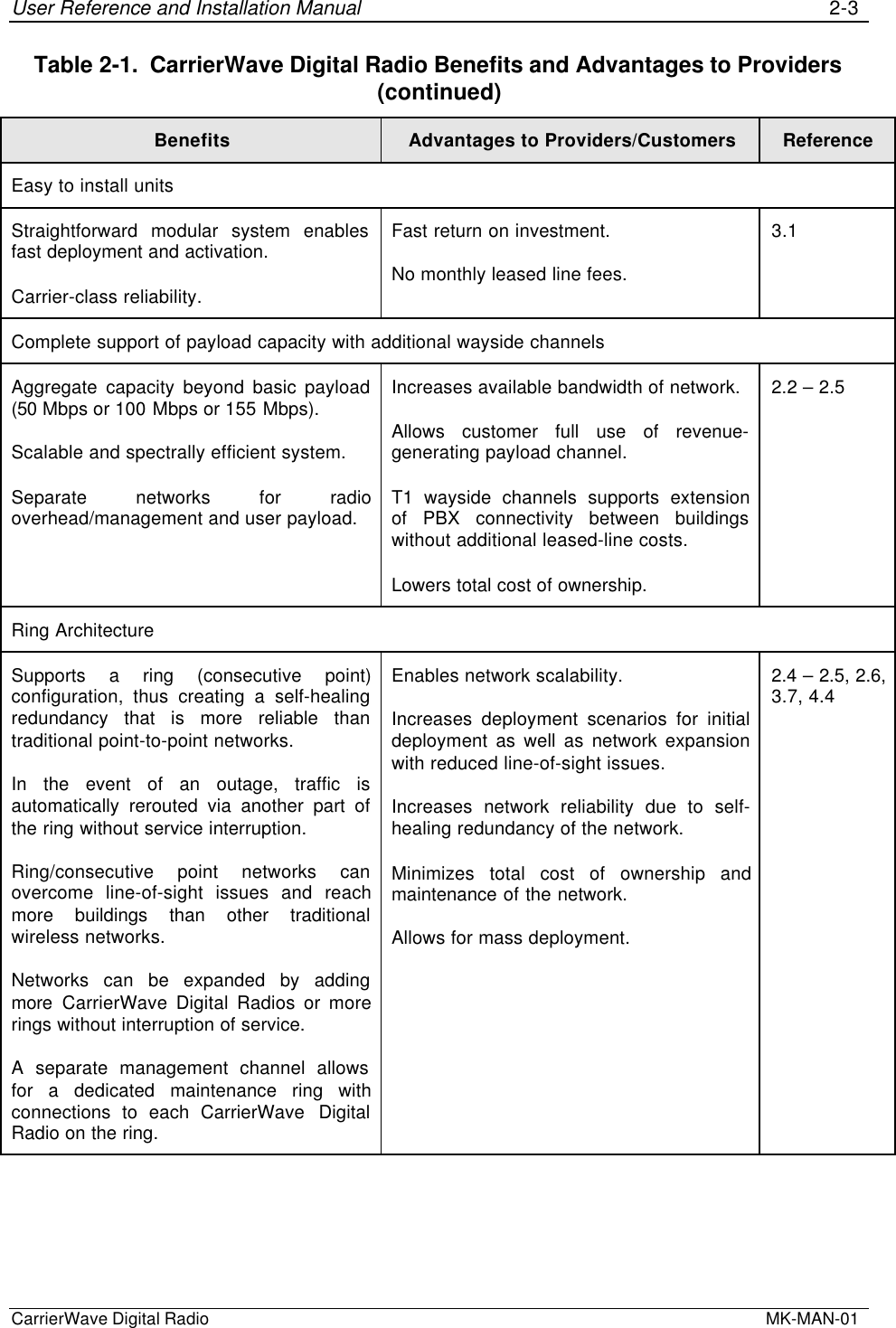
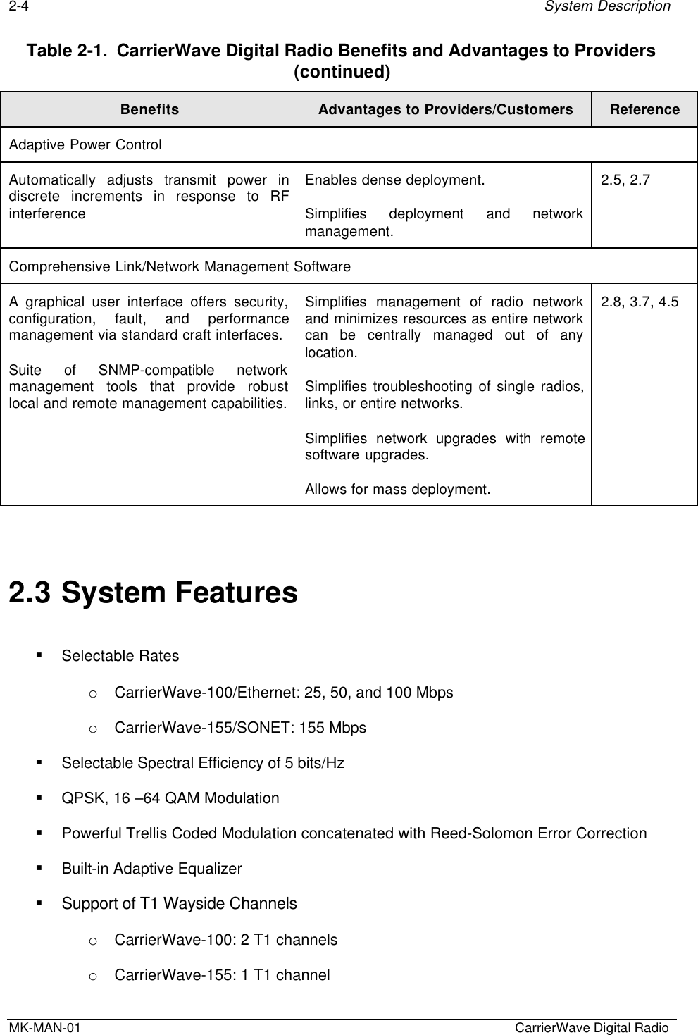
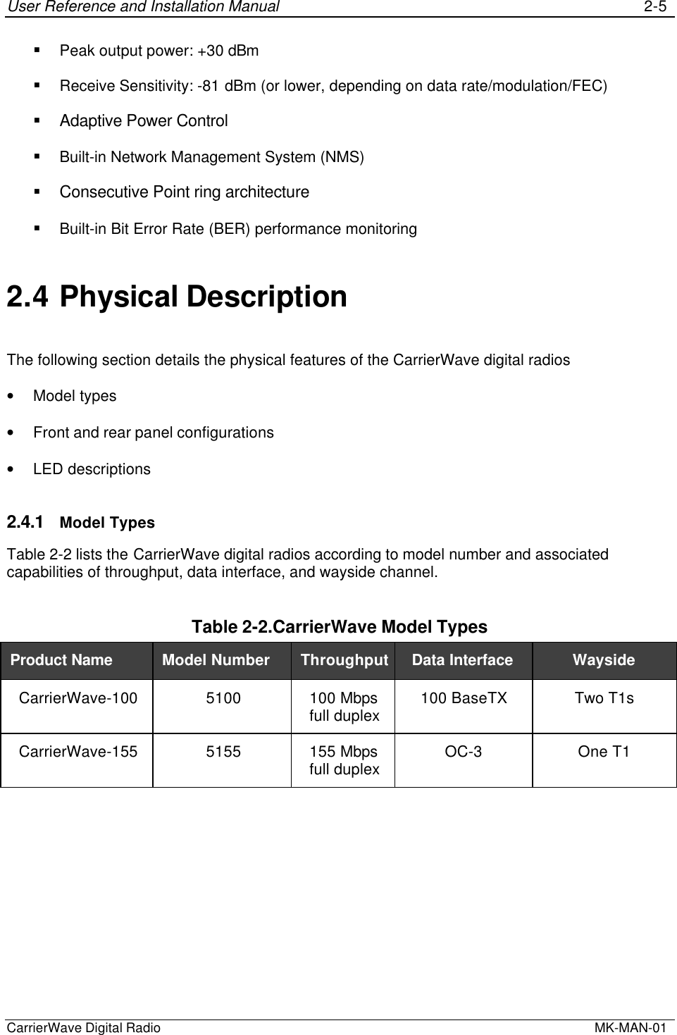
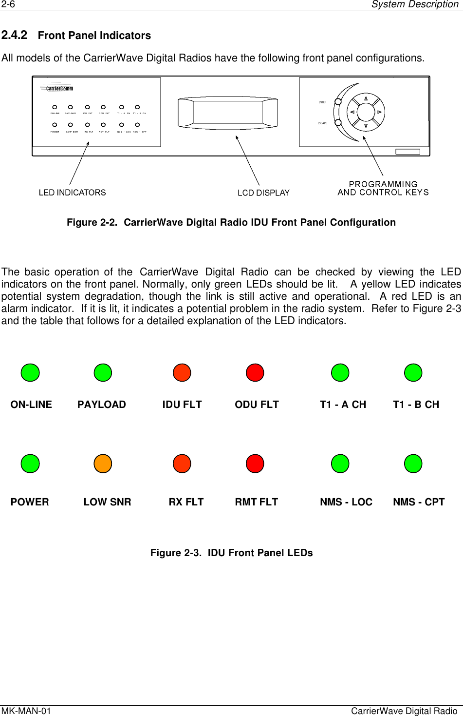
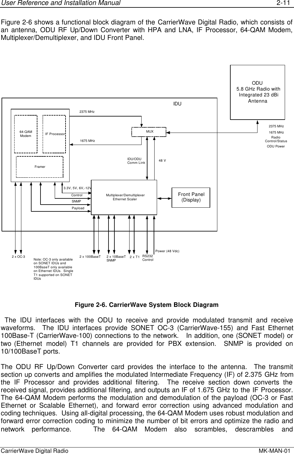
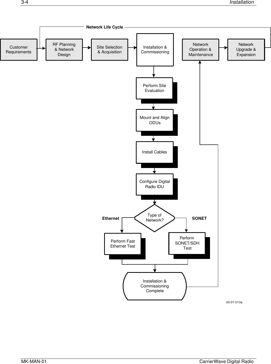
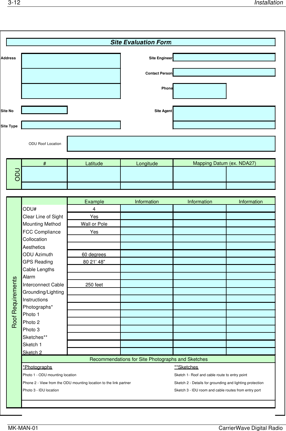
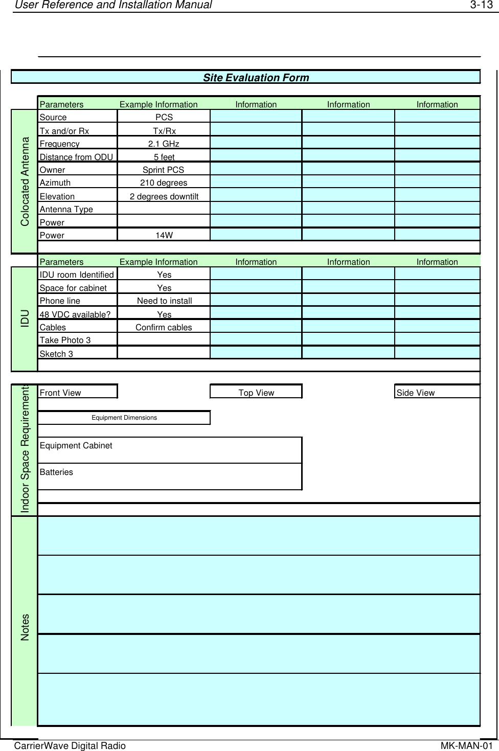
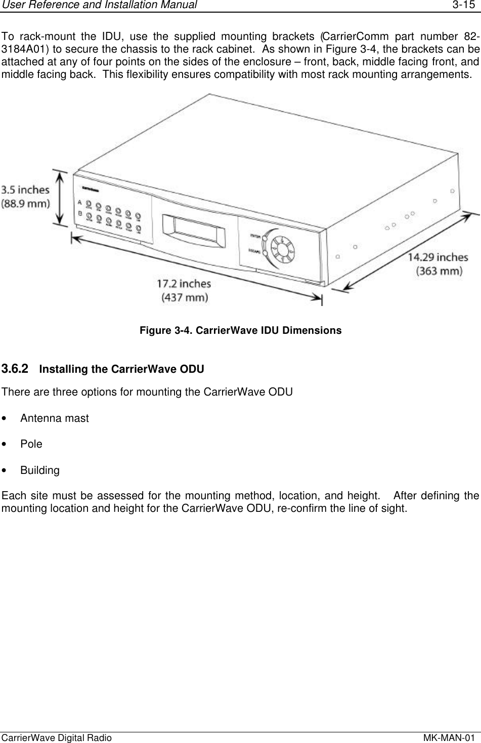
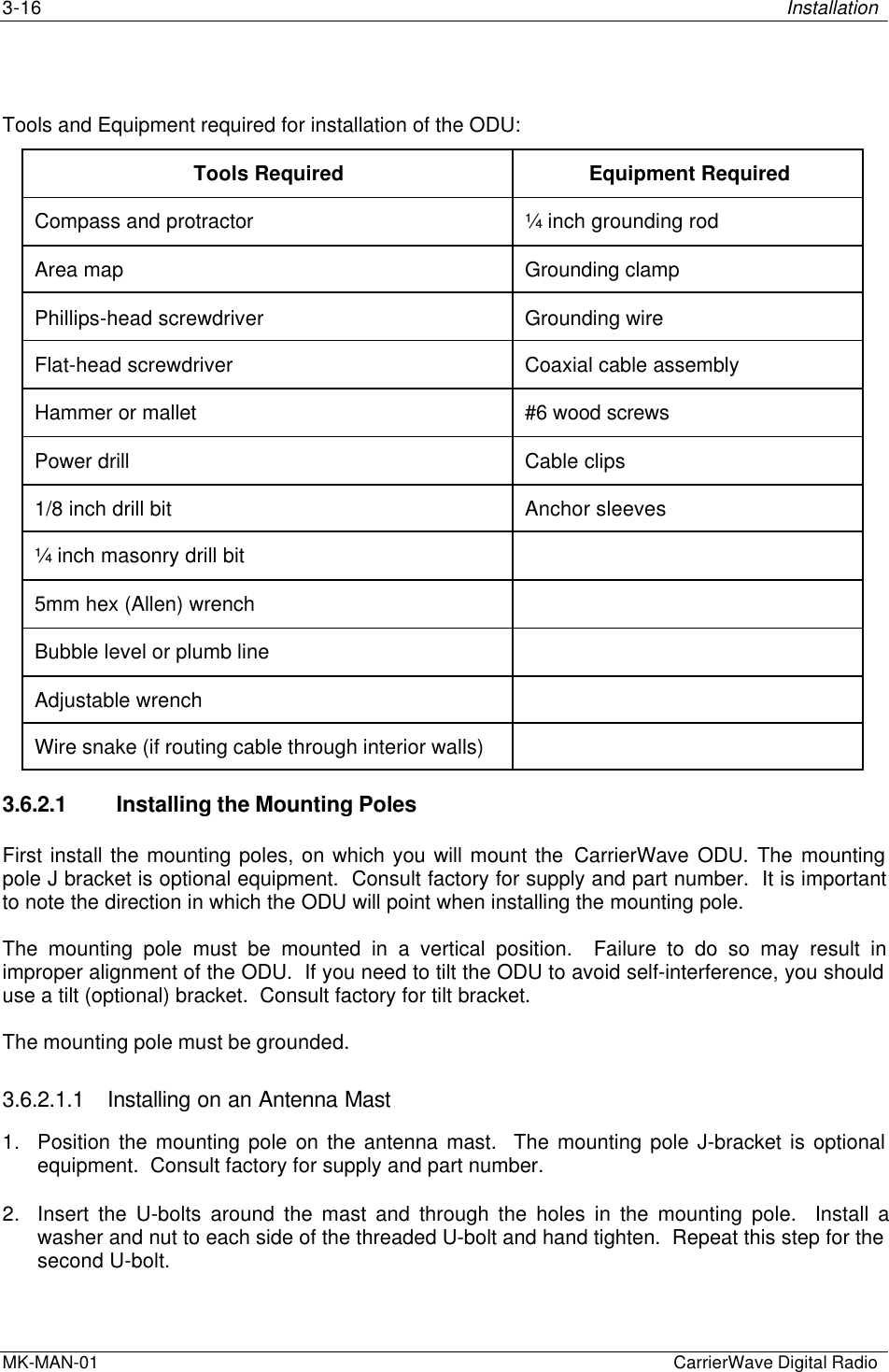
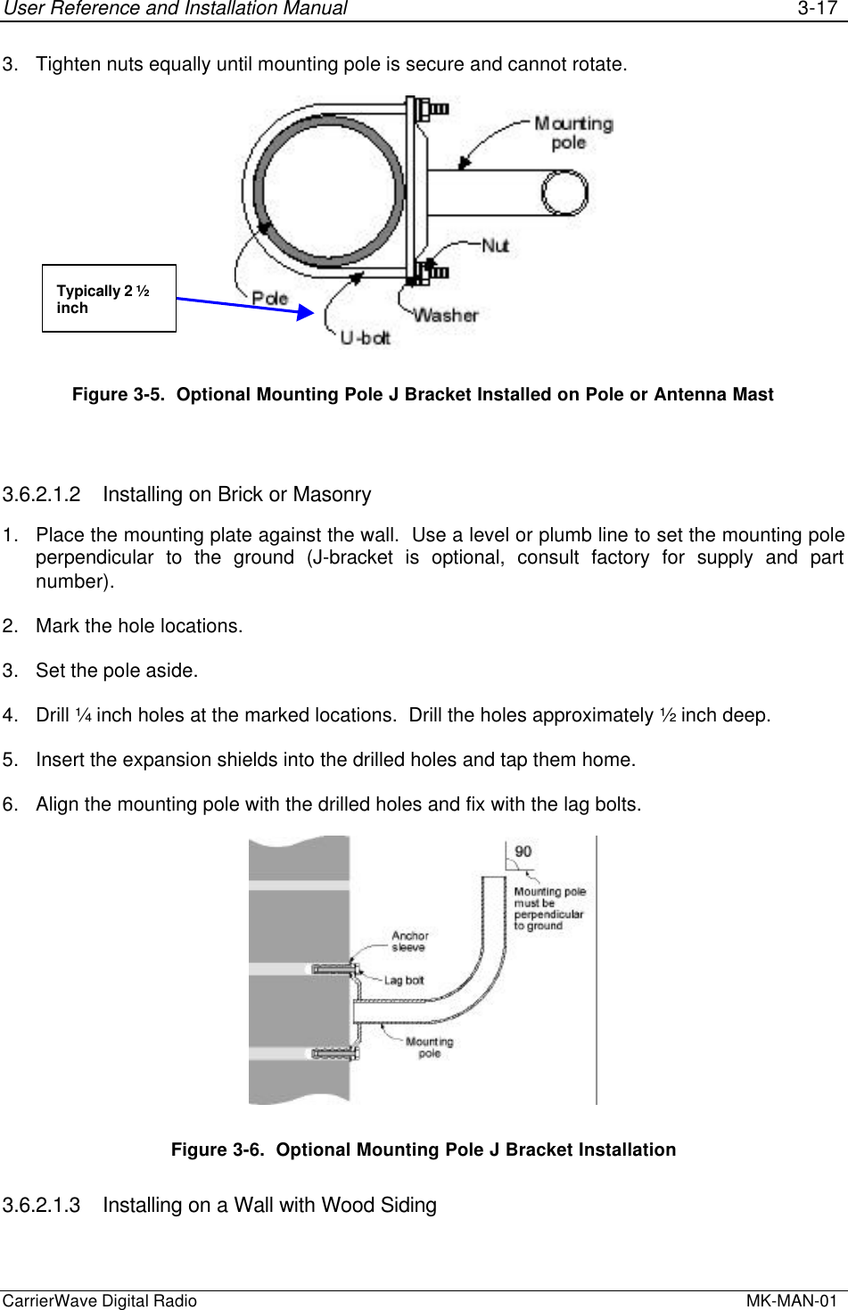
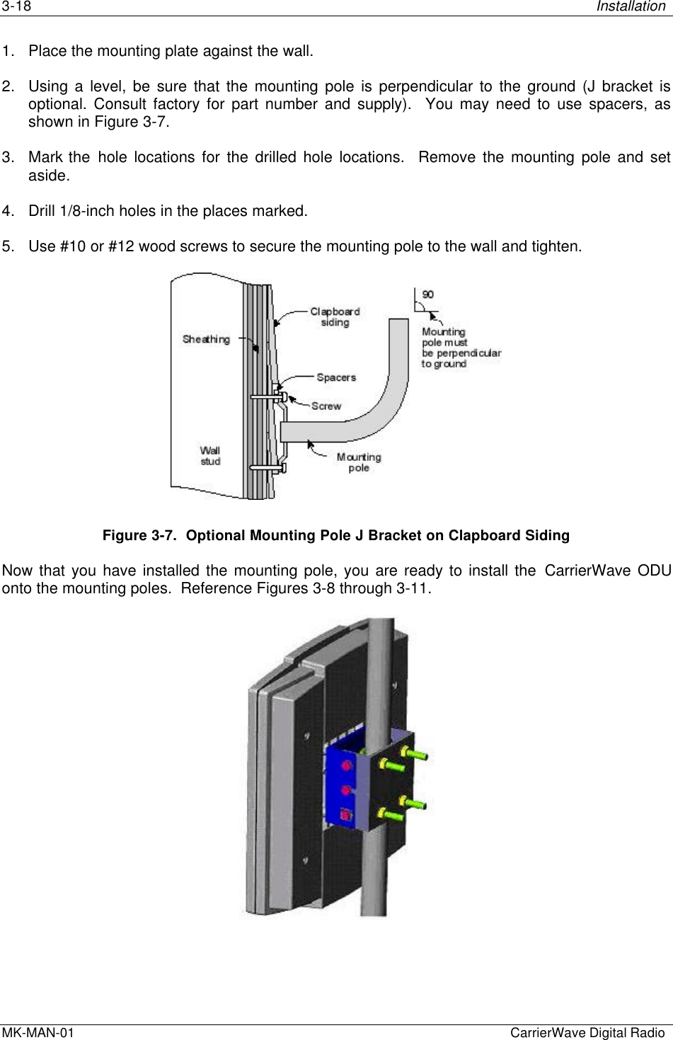
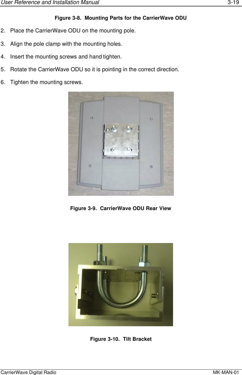
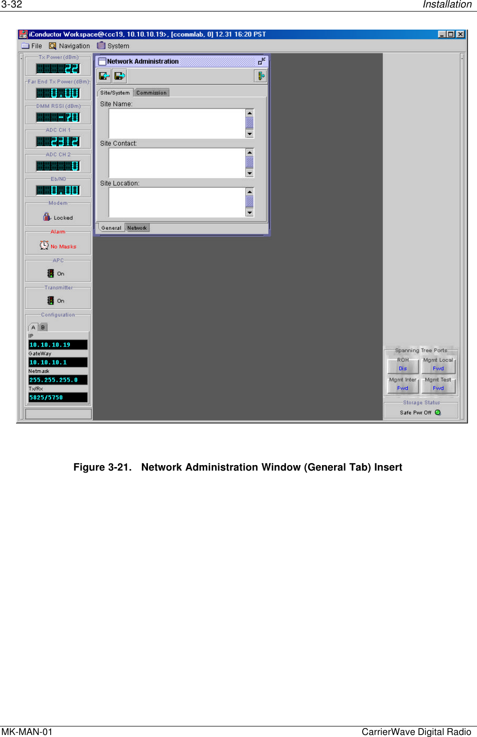
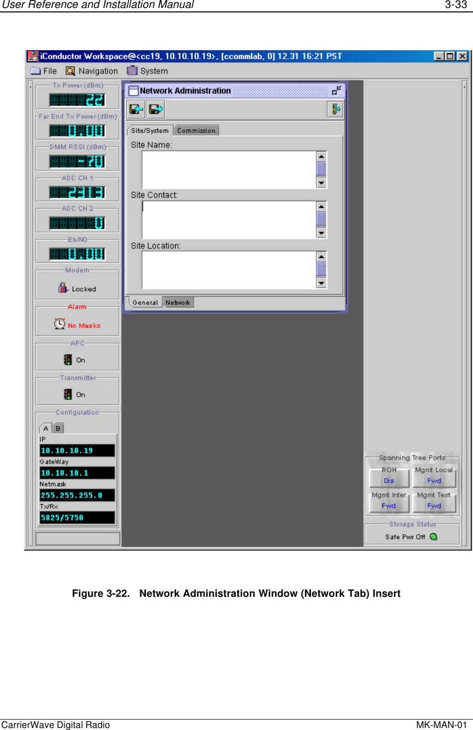
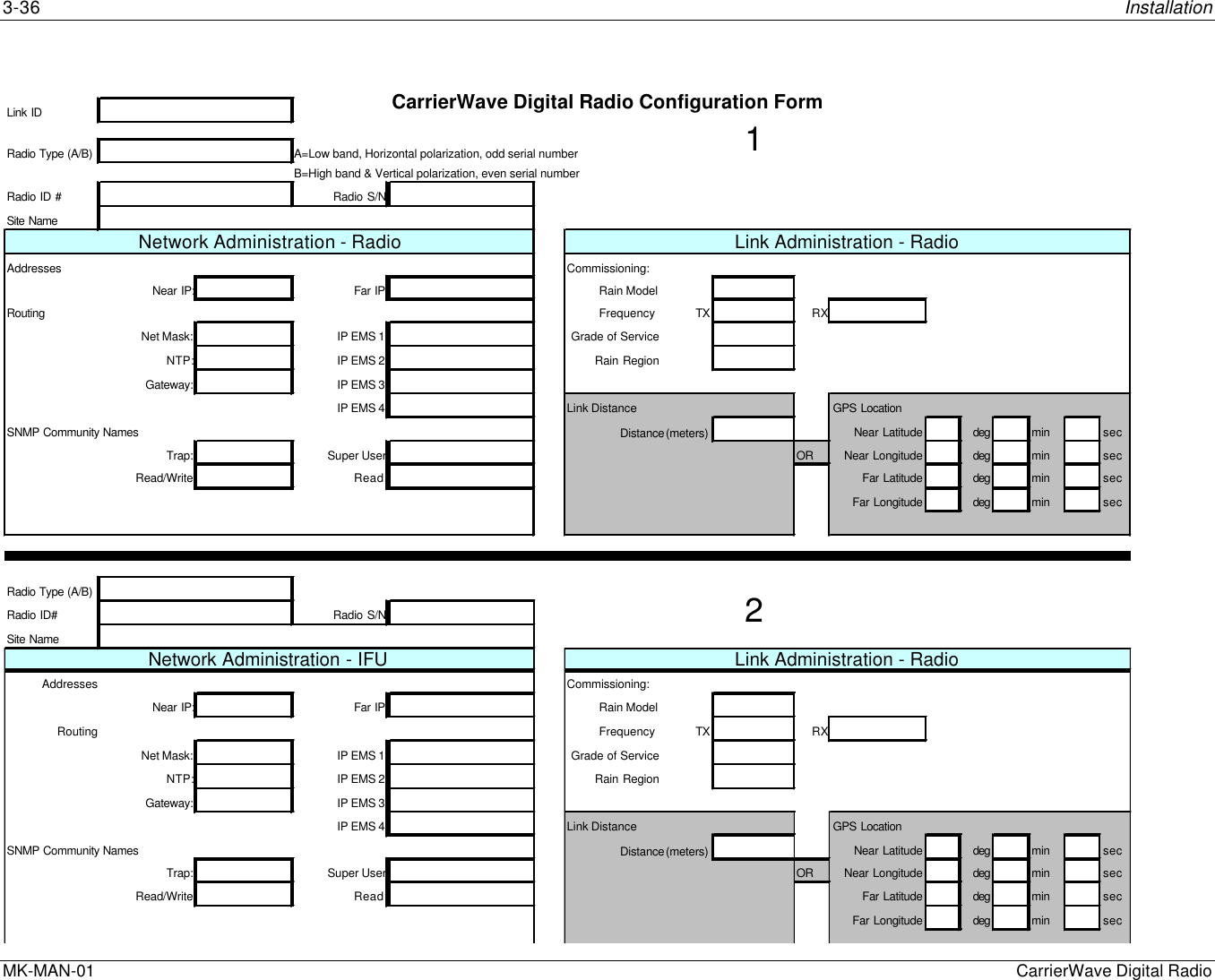
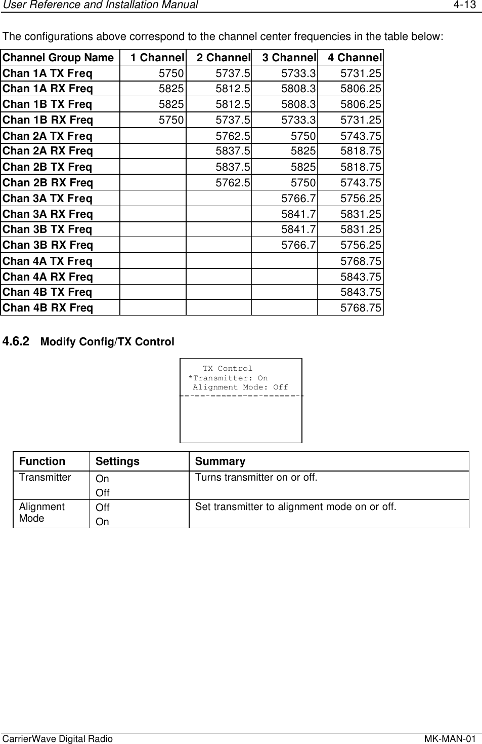
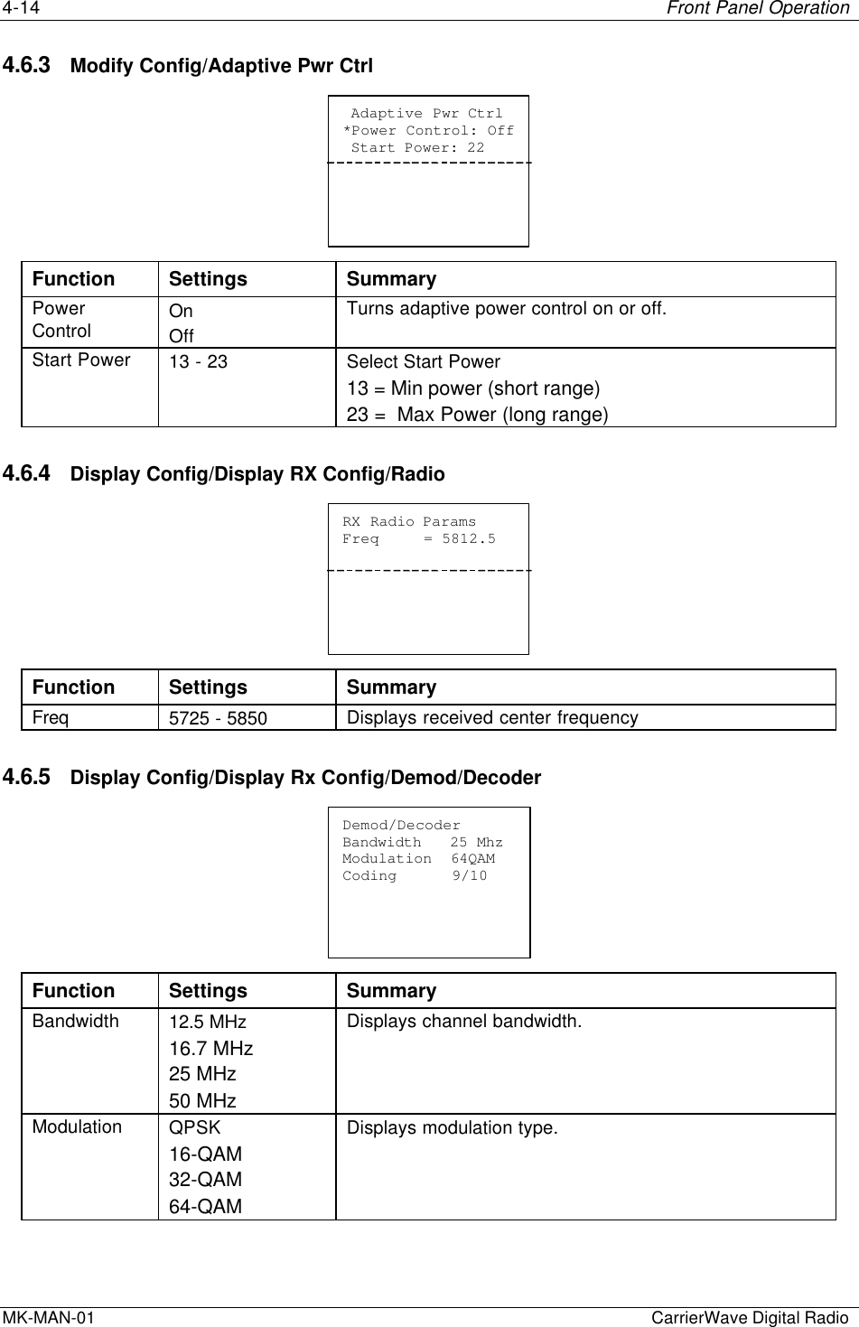
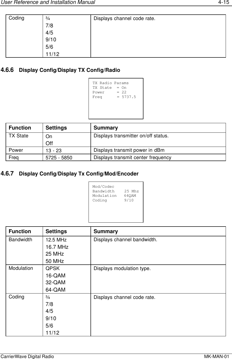
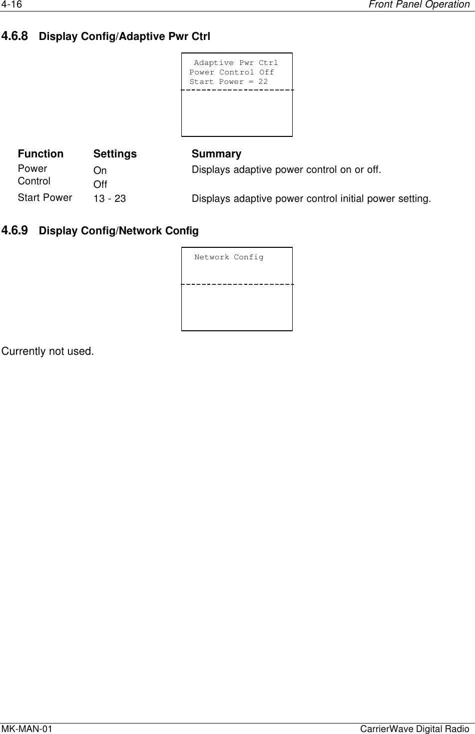
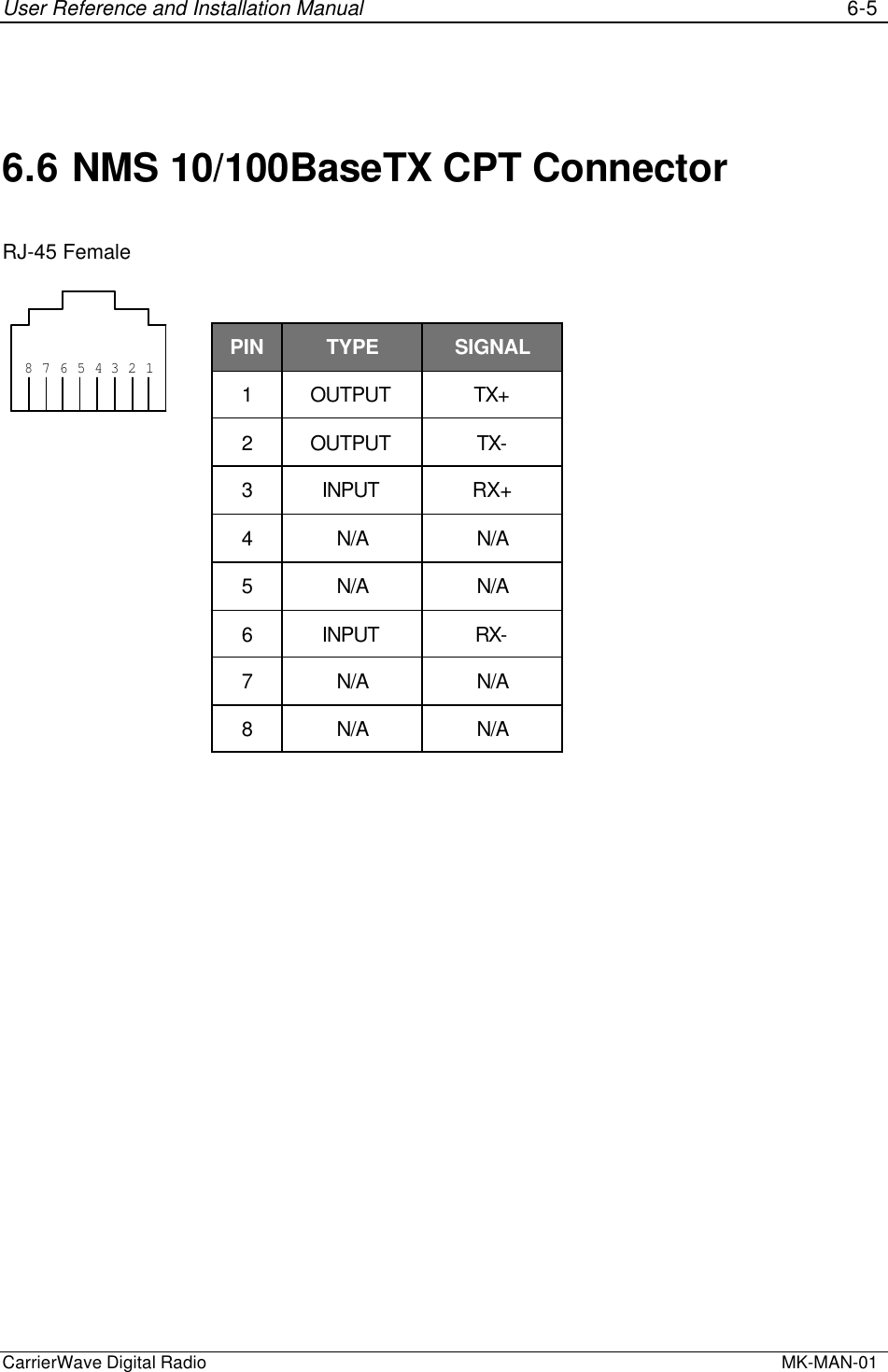
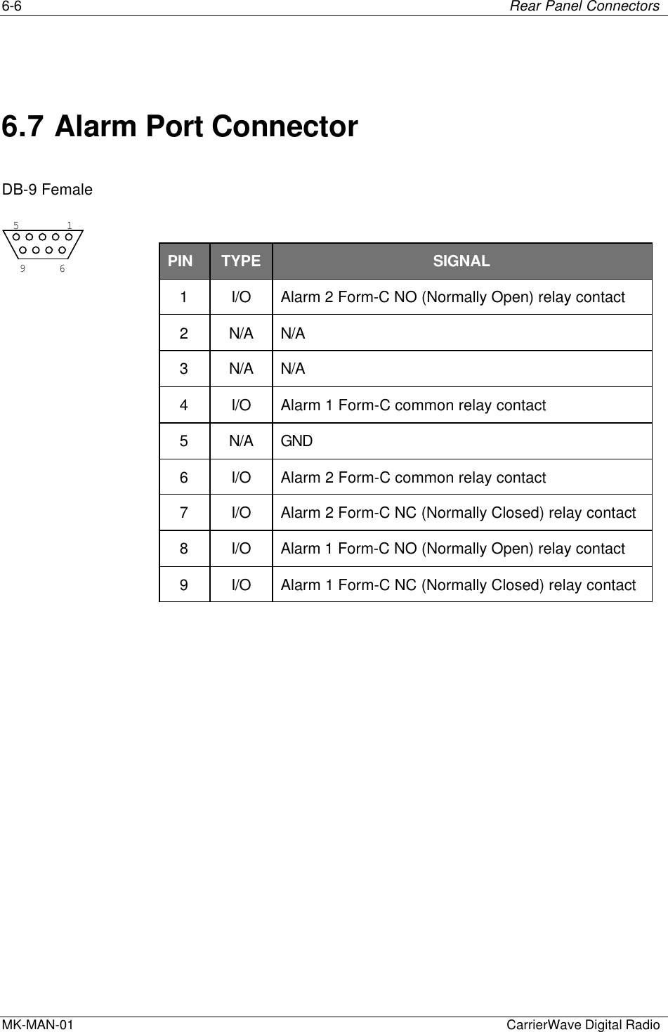
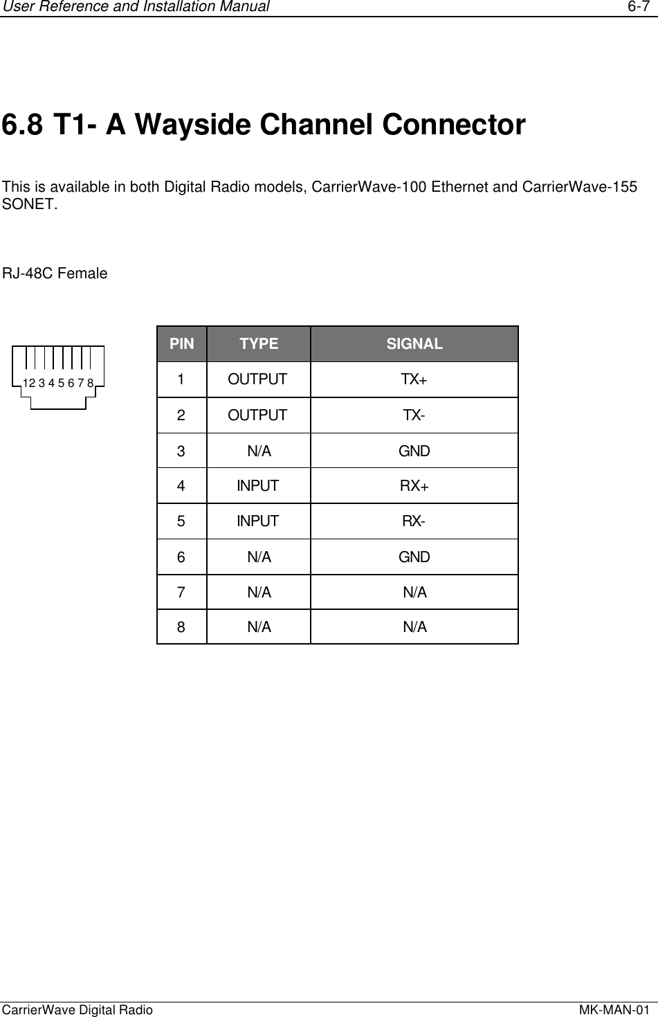
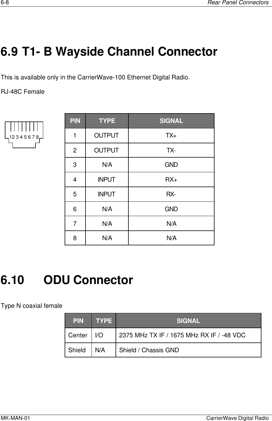
Installation manual
Manual revised
Navigation menu
Upload a User Manual
Namespaces
Wiki Guide
HTML
PDF
Info
Views
User Manual
Discussion / Help
Navigation