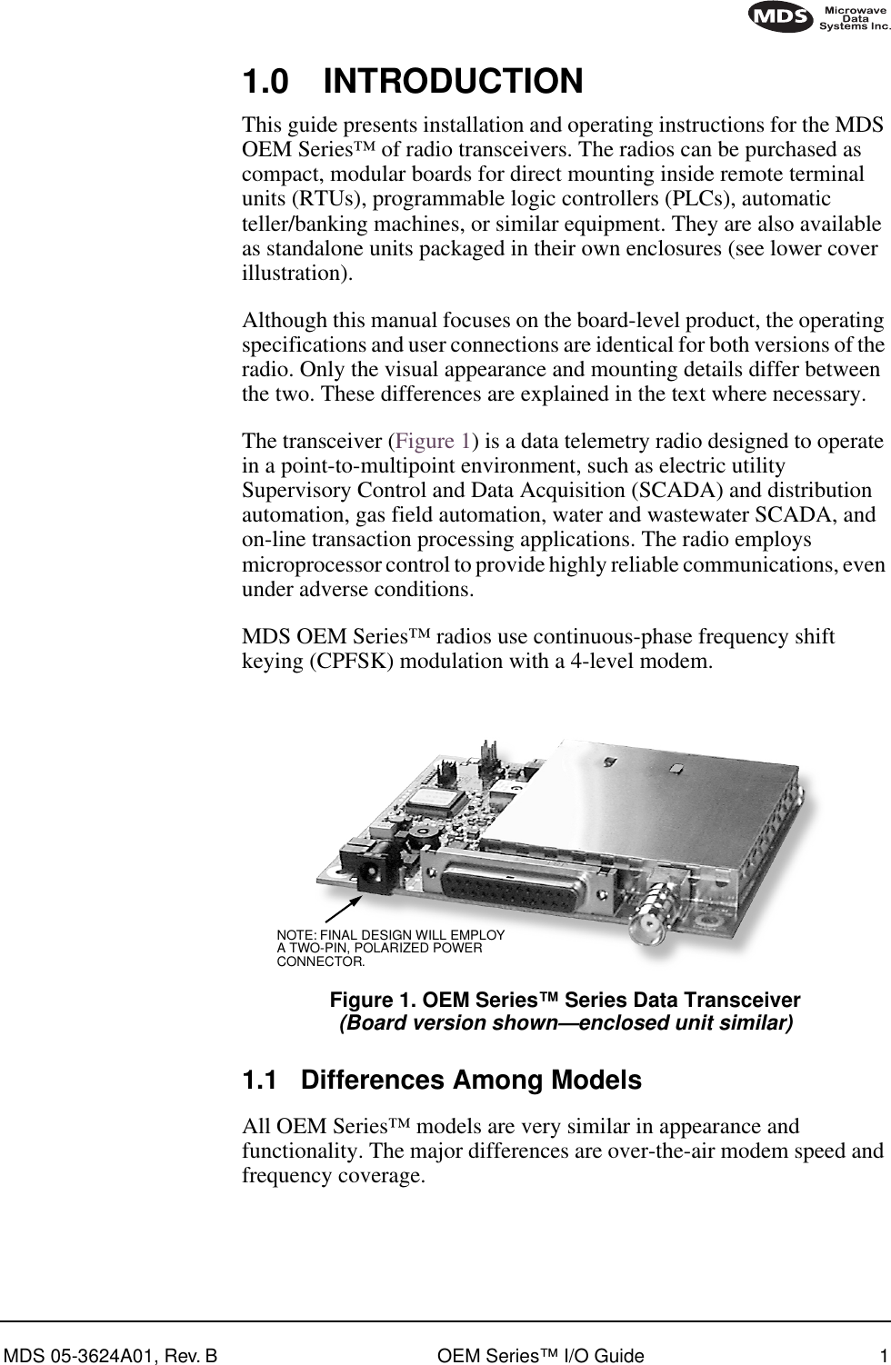
GE MDS DS-EL705-9 EL705 OEM Series Radio User Manual OEM 900 Series Body
GE MDS LLC EL705 OEM Series Radio OEM 900 Series Body
GE MDS >
Contents
- 1. Operating Instructions Part 1 of 2
- 2. Operating Instructions Part 2 of 2
Operating Instructions Part 2 of 2
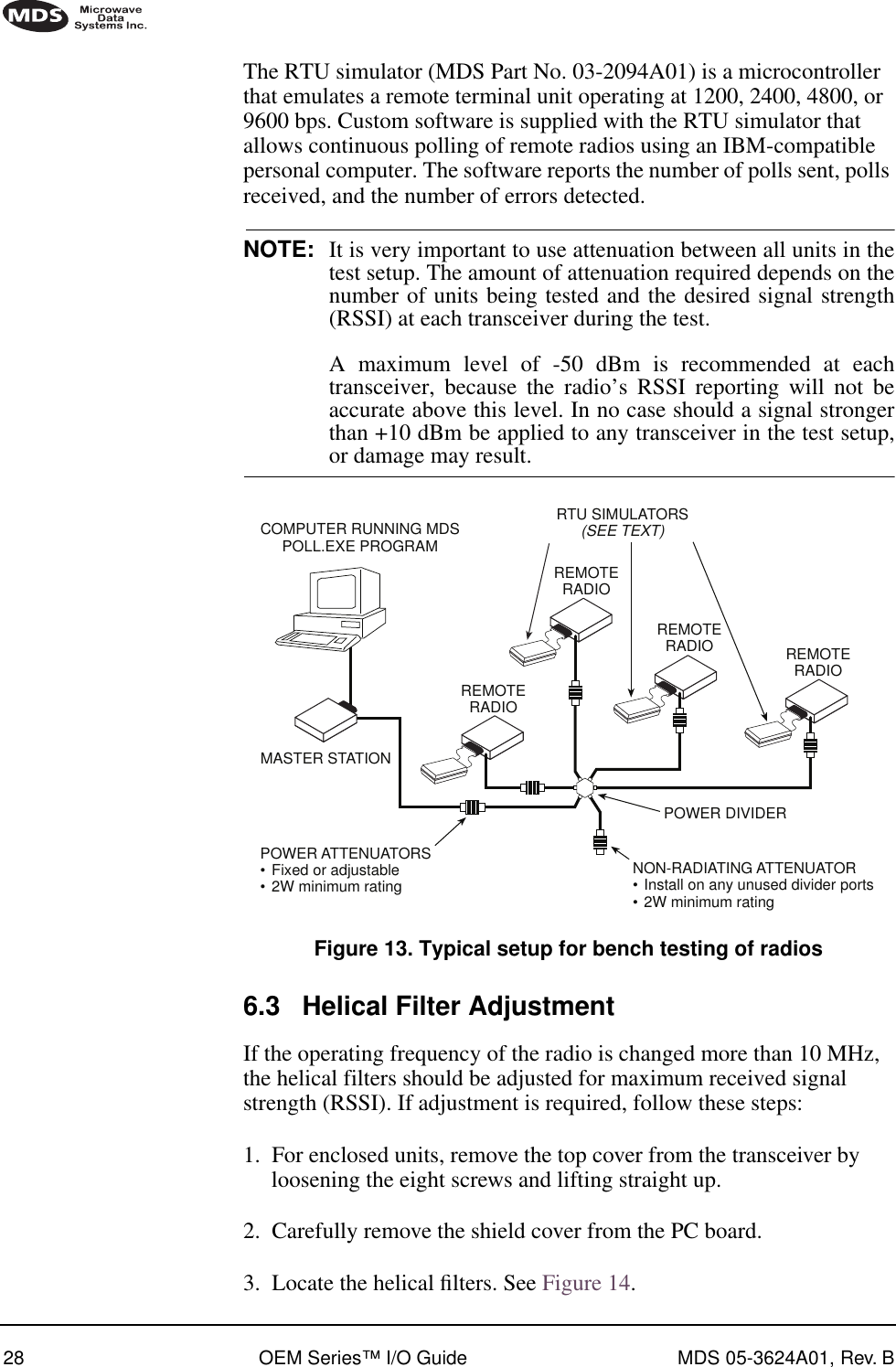
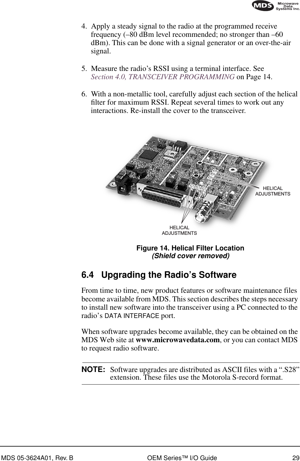
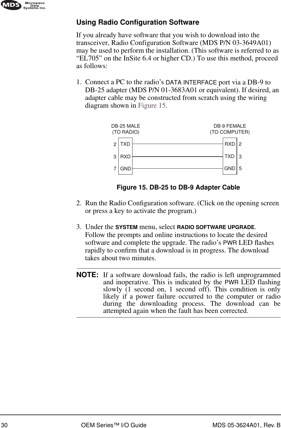
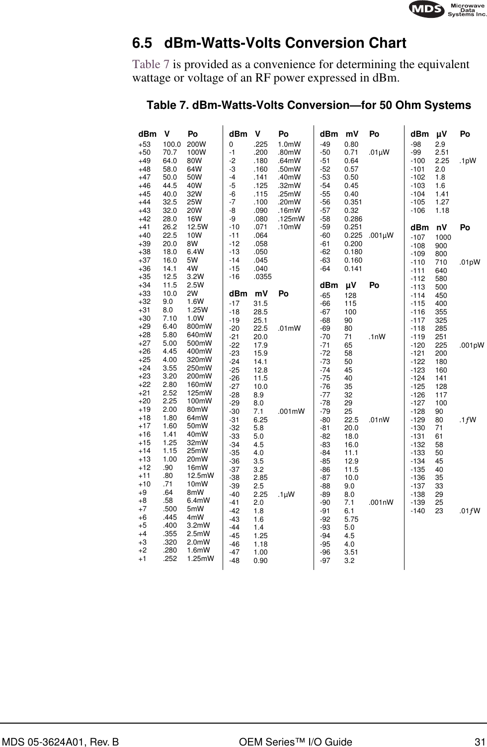
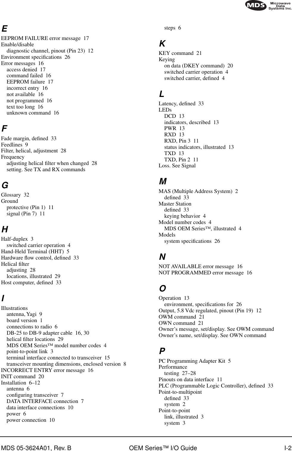
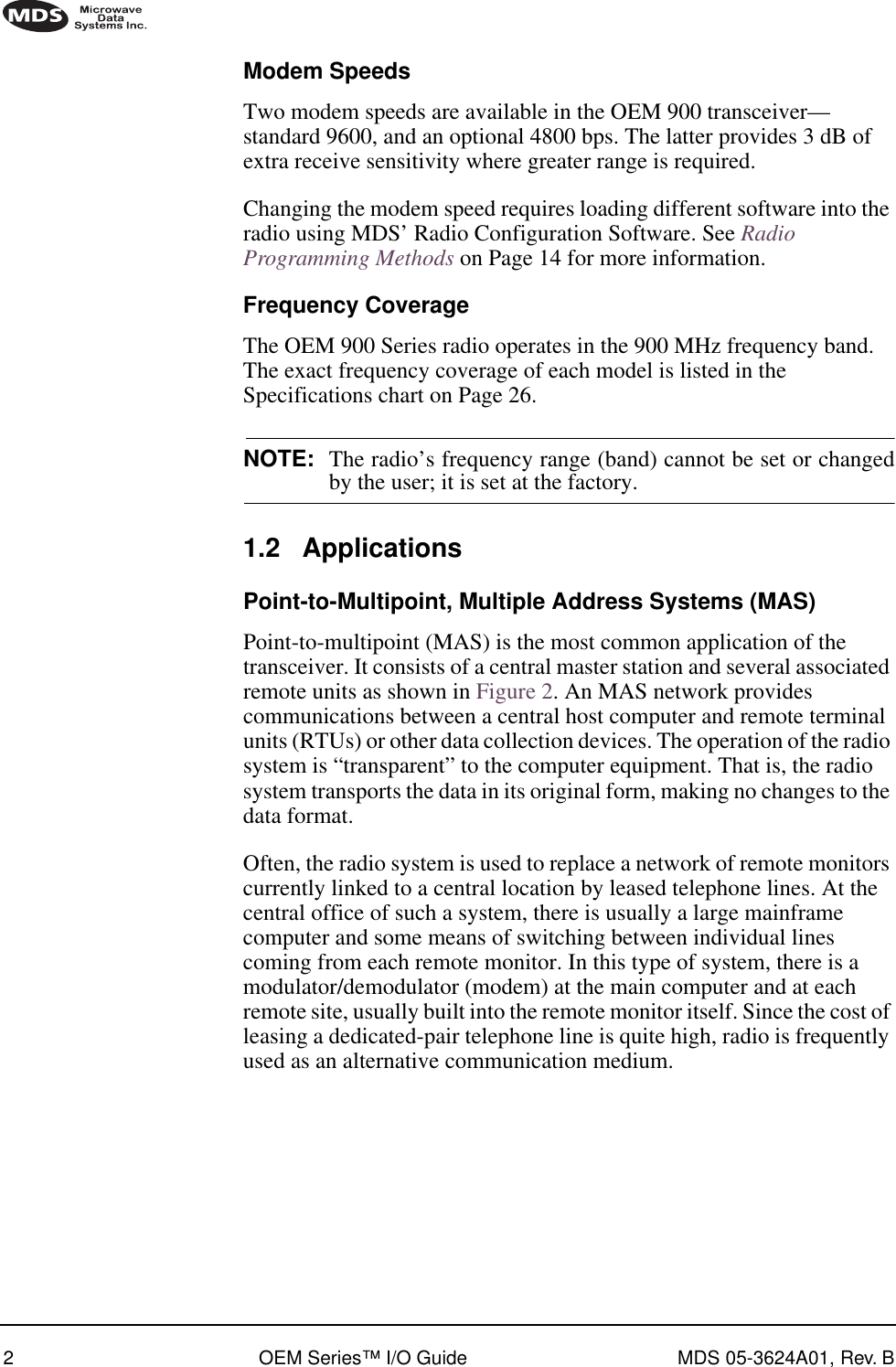
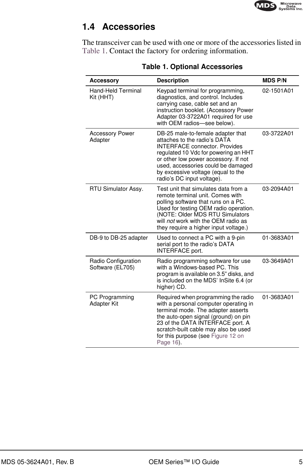
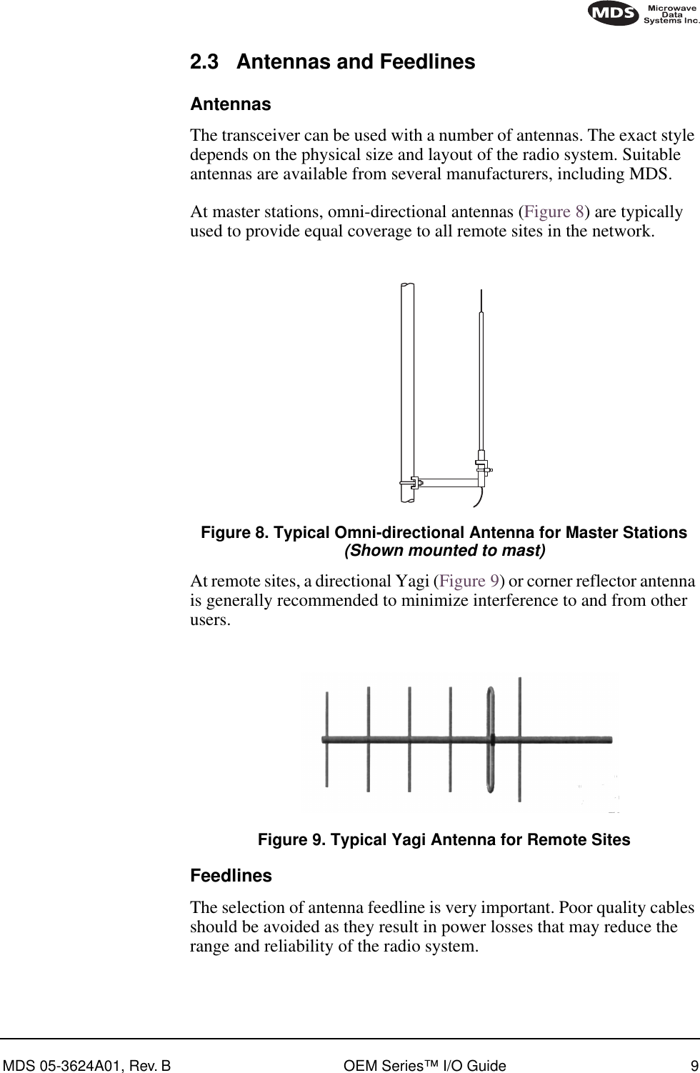
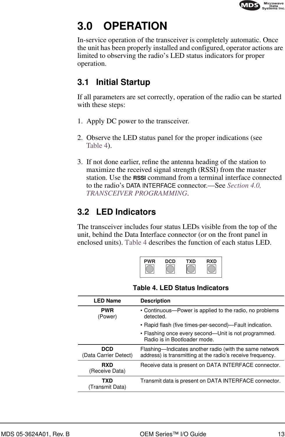
![MDS 05-3624A01, Rev. B OEM Series I/O Guide i TABLE OF CONTENTS 1.0 INTRODUCTION .........................................................................1 1.1 Differences Among Models ..............................................................1Modem Speeds ..................................................................................2Frequency Coverage ..........................................................................21.2 Applications ......................................................................................2Point-to-Multipoint, Multiple Address Systems (MAS) ........................2Point-to-Point System .........................................................................3Switched Carrier Operation ................................................................4Single Frequency (Simplex) Operation...............................................41.3 Model Number Codes ......................................................................41.4 Accessories ......................................................................................5 2.0 INSTALLATION ............................................................................6 2.1 Installation Steps ..............................................................................62.2 Mounting the Transceiver .................................................................8Transceiver Board...............................................................................8Enclosed Transceiver..........................................................................82.3 Antennas and Feedlines ..................................................................9Antennas ............................................................................................9Feedlines ............................................................................................92.4 Power Connection ..........................................................................10Conservation (Sleep Mode)..............................................................102.5 Data Interface Connections ............................................................10 3.0 OPERATION..............................................................................13 3.1 Initial Startup ..................................................................................133.2 LED Indicators ................................................................................13 4.0 TRANSCEIVER PROGRAMMING ............................................14 4.1 Radio Programming Methods ........................................................14 PC with Radio Configuration Software ..........................................14À PC in Terminal Mode....................................................................14Ã Handheld Terminal (HHT).............................................................144.2 PC Connection and Startup ...........................................................144.3 Keyboard Commands .....................................................................16Entering Commands.........................................................................16Error Messages ................................................................................164.4 Detailed Command Descriptions ...................................................18ADDR [NONE | 1–255] .....................................................................18AMASK [0000 0000–FFFF FFFF] ....................................................18BAUD [xxxxx abc] .............................................................................19CTS [0–255] .....................................................................................19CTSHOLD [0–60000] .......................................................................19](https://usermanual.wiki/GE-MDS/DS-EL705-9.Operating-Instructions-Part-2-of-2/User-Guide-161471-Page-2.png)
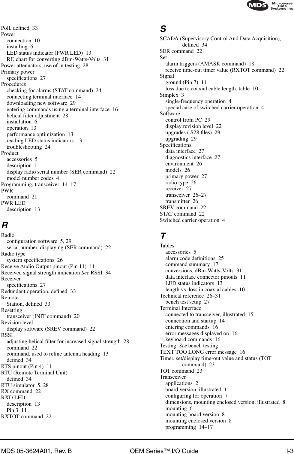
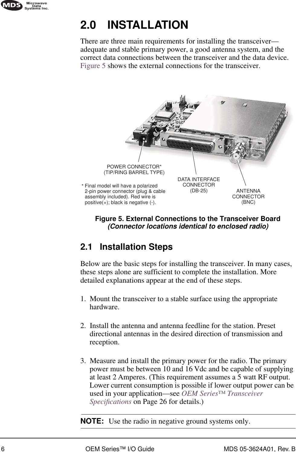
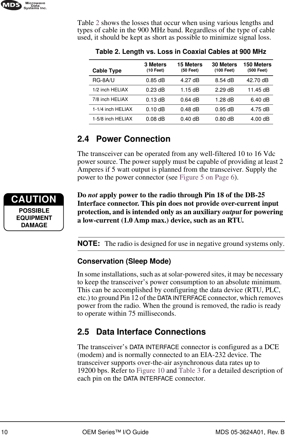
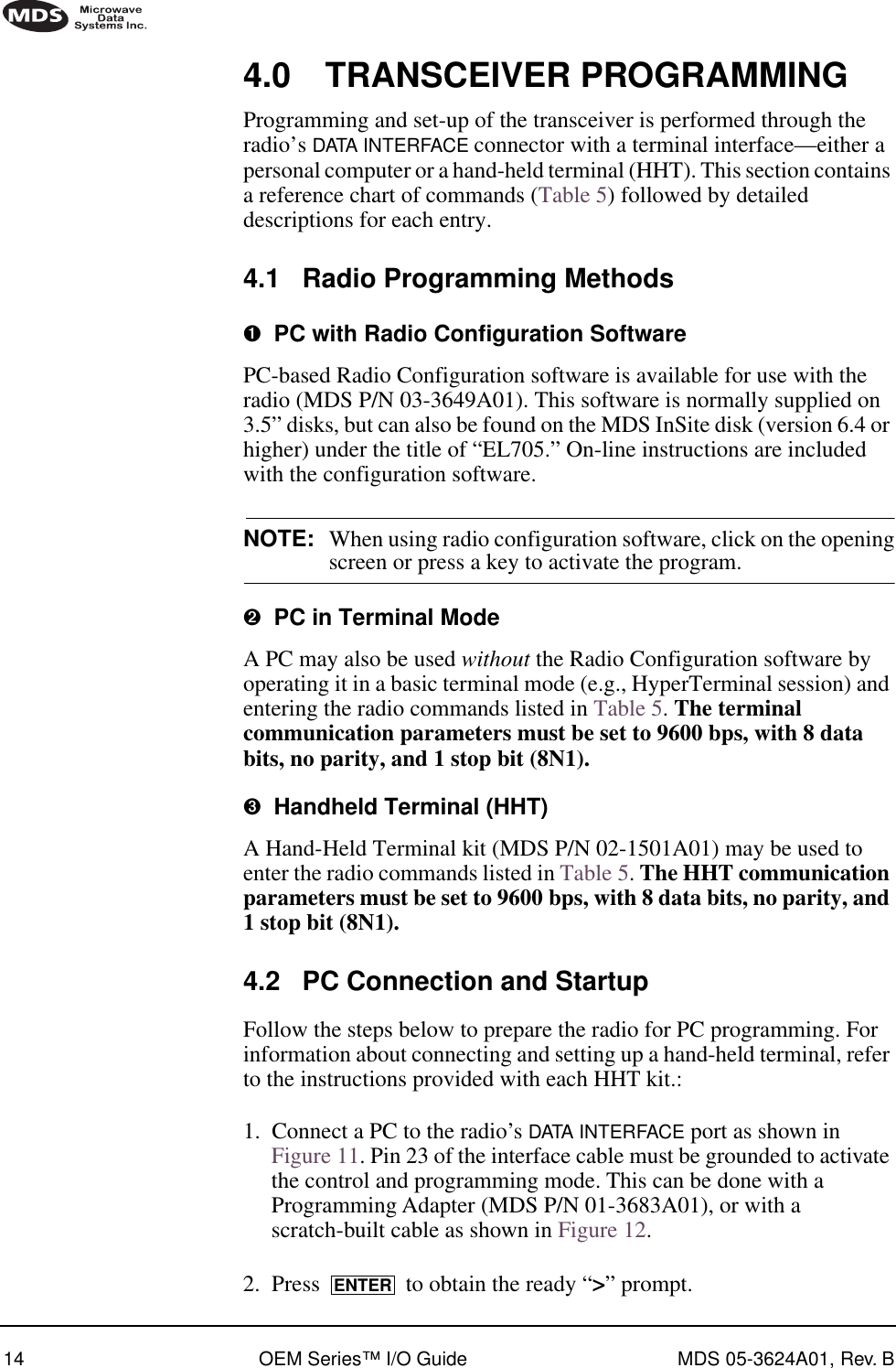
![ii OEM Series I/O Guide MDS 05-3624A01, Rev. B DEVICE [DCE | CTS KEY] ...............................................................20DKEY................................................................................................20INIT...................................................................................................20KEY ..................................................................................................21OWM [XXX...] ...................................................................................21OWN [XXX...]....................................................................................21PWR [L | M | H].................................................................................21RSSI and RSSI!................................................................................22RX [xxx.xxx]......................................................................................22RXTOT [NONE | 1–255] ...................................................................22SER ..................................................................................................22SREV................................................................................................22STAT .................................................................................................22TOT [1–255 | ON | OFF] ...................................................................23TX [xxx.xxx] ......................................................................................23 5.0 TROUBLESHOOTING...............................................................24 5.1 LED Indicators ................................................................................245.2 Event Codes ...................................................................................24Checking for Alarms—STAT command.............................................24Major Alarms vs. Minor Alarms.........................................................25Event Code Definitions .....................................................................25 6.0 TECHNICAL REFERENCE .......................................................26 6.1 OEM Series™ Transceiver Specifications ......................................266.2 Bench Testing Setup ......................................................................276.3 Helical Filter Adjustment ................................................................286.4 Upgrading the Radio’s Software .....................................................29Using Radio Configuration Software.................................................306.5 dBm-Watts-Volts Conversion Chart ................................................31 7.0 GLOSSARY OF TERMS............................................................32](https://usermanual.wiki/GE-MDS/DS-EL705-9.Operating-Instructions-Part-2-of-2/User-Guide-161471-Page-3.png)
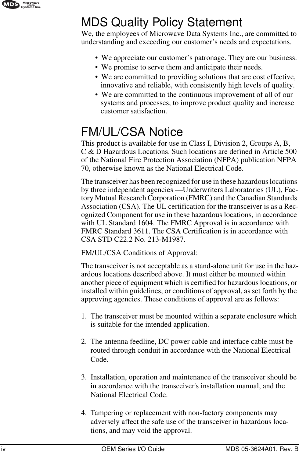

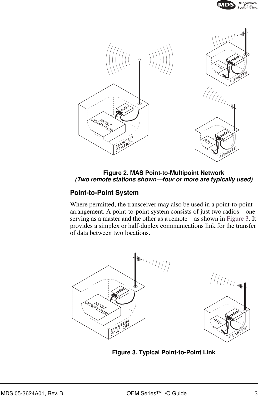
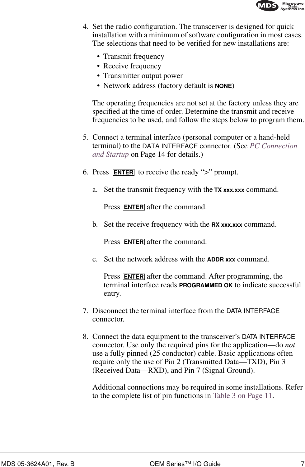
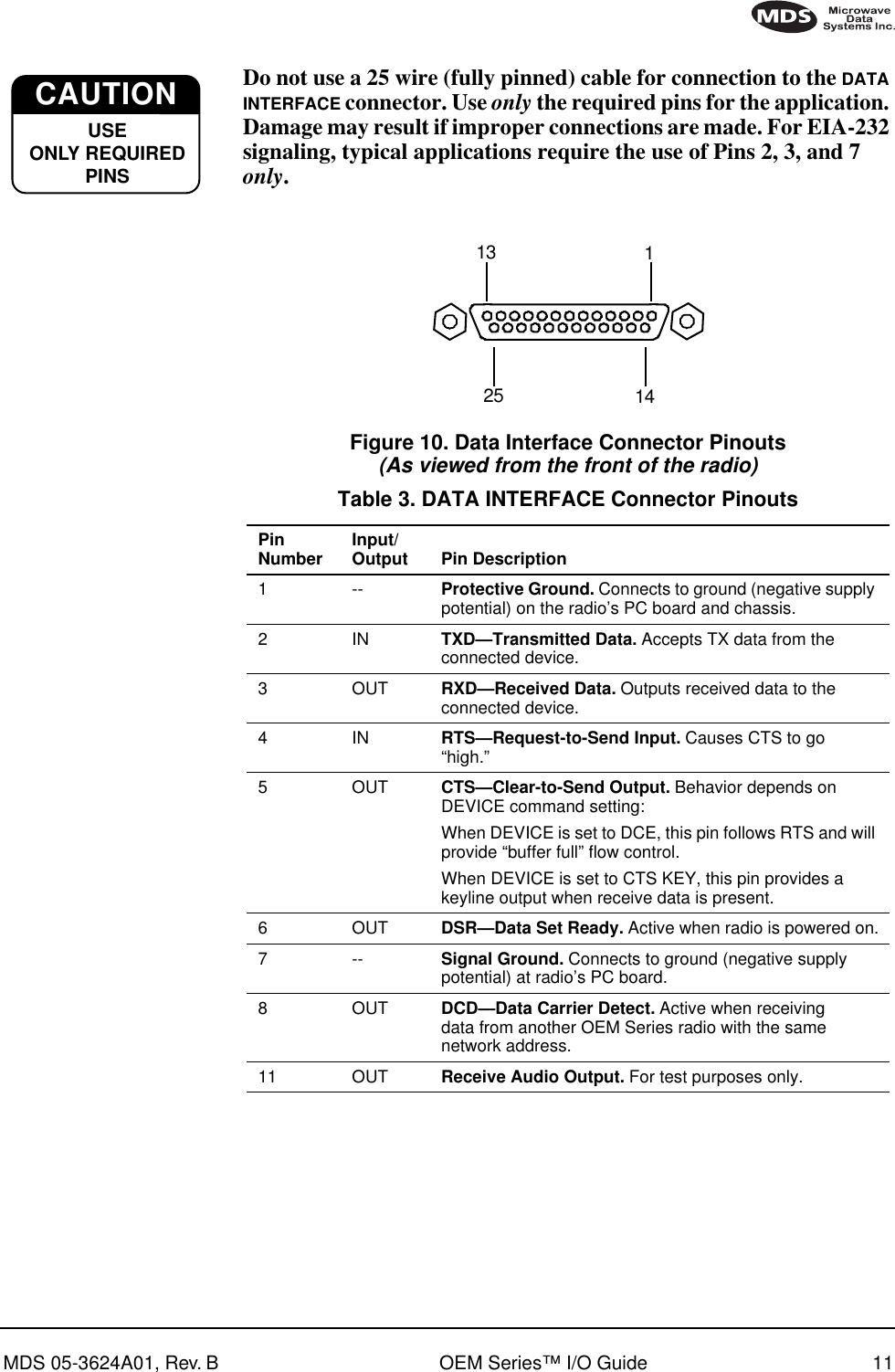
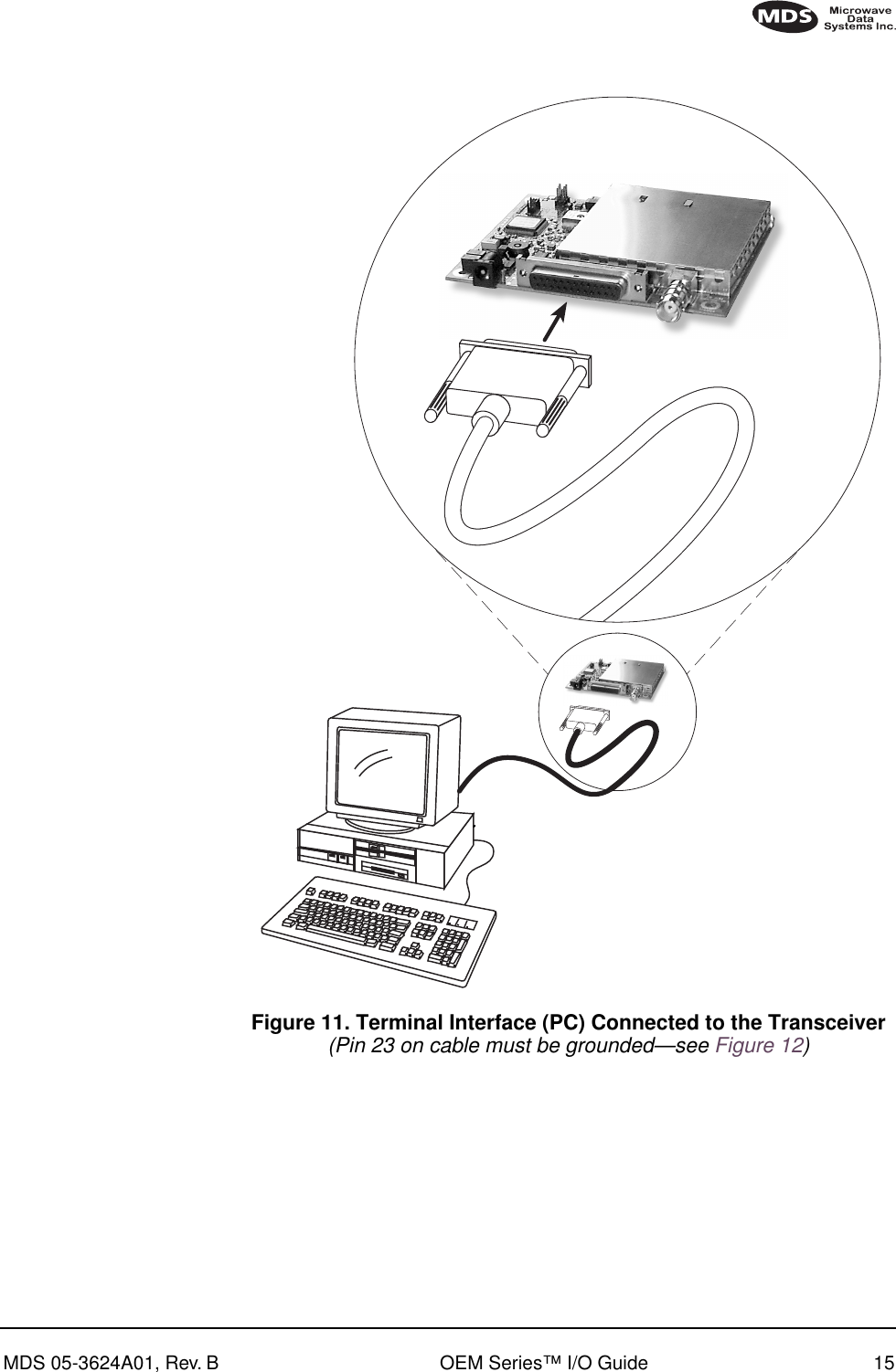
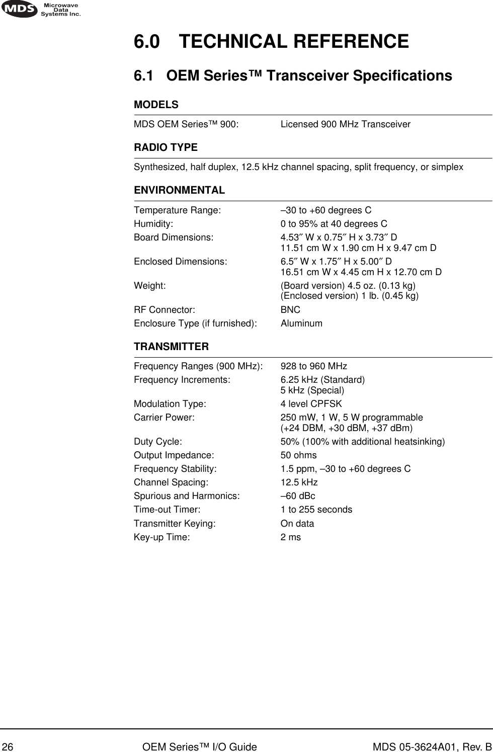
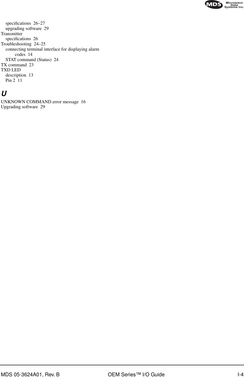
![16 OEM Series™ I/O Guide MDS 05-3624A01, Rev. BInvisible place holderFigure 12. DB-25 to DB-9 Adapter Cable(For PC control and programming)4.3 Keyboard CommandsTable 5 is a reference chart of software commands for the transceiver. Programmable information is shown in brackets [ ] following the command name. See section 4.4 following the table for detailed command descriptions.Entering CommandsTo enter a command, type the command, followed by an keystroke. For programming commands, the command is followed by and the appropriate information or values, then .Error MessagesListed below are some possible error messages that may be encountered when using the terminal interface:UNKNOWN COMMAND—The command was not recognized. Refer to the command description for command usage information.INCORRECT ENTRY—The command format or its associated values were not valid. Refer to the command description for command usage information.COMMAND FAILED—The command was unable to successfully complete. This may indicate an internal software problem.NOT PROGRAMMED—Software was unable to program the internal radio memory or the requested item was not programmed.This is a serious internal radio error. Contact MDS for assistance.TEXT TOO LONG—Response to OWN or OWM command when too many characters have been entered. Refer to the command description for command usage information.NOT AVAILABLE—The entered command or parameter was valid, but it referred to a currently unavailable choice. Refer to the command description for command usage information.RXDTXDGND235DB-9 FEMALE(TO COMPUTER)TXDRXDGND237DB-25 MALE(TO RADIO)Diagnostics Open23ENTERSPACE ENTER](https://usermanual.wiki/GE-MDS/DS-EL705-9.Operating-Instructions-Part-2-of-2/User-Guide-161471-Page-23.png)
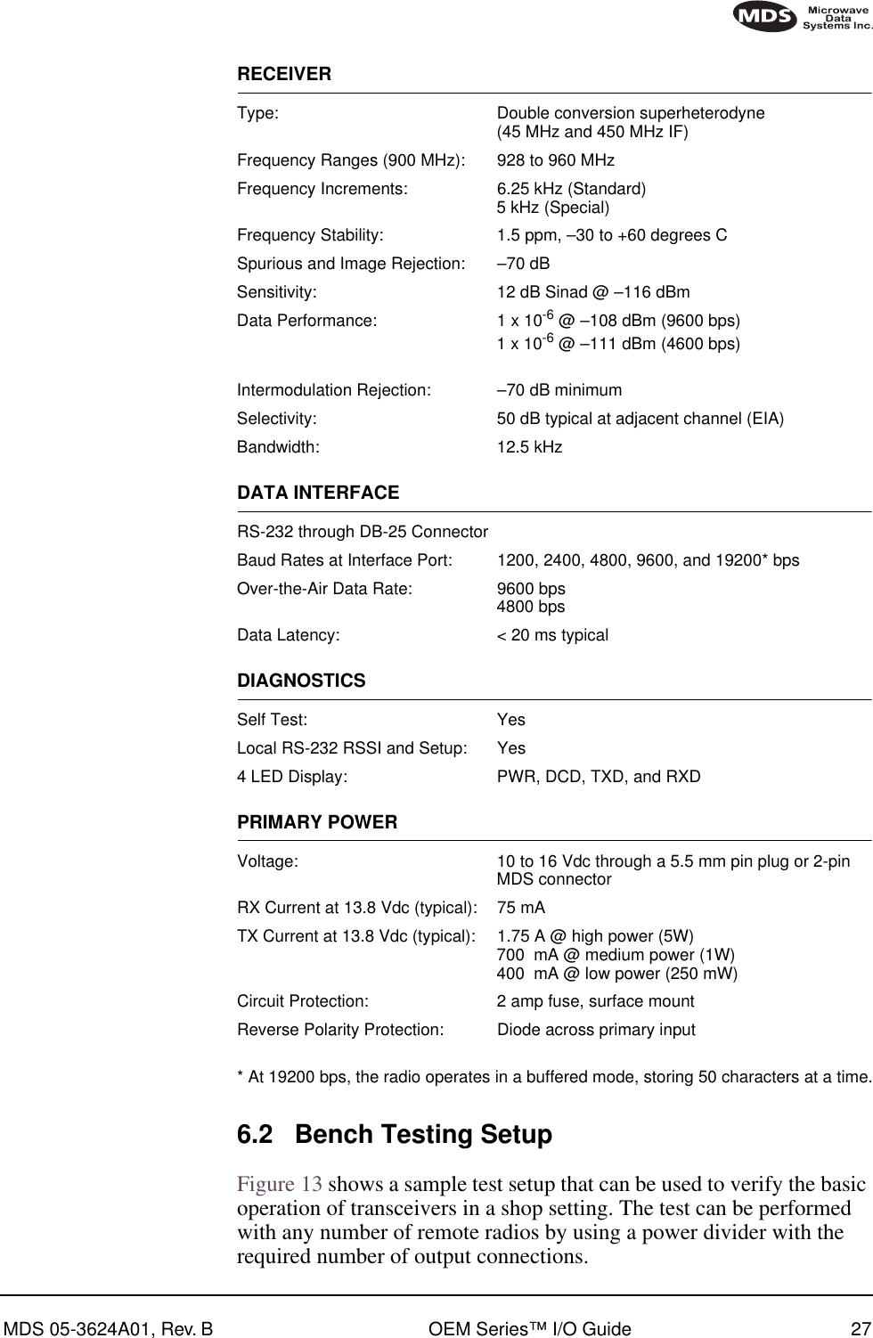
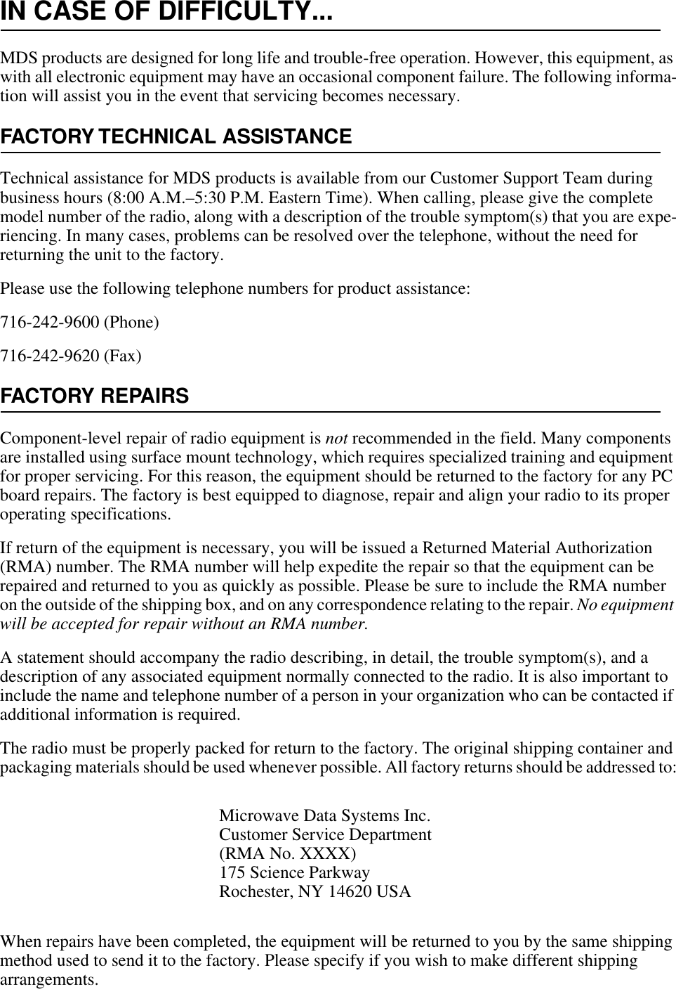
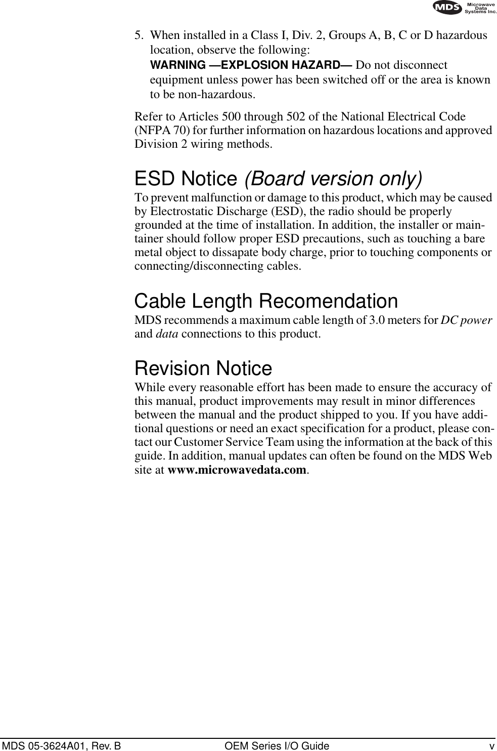
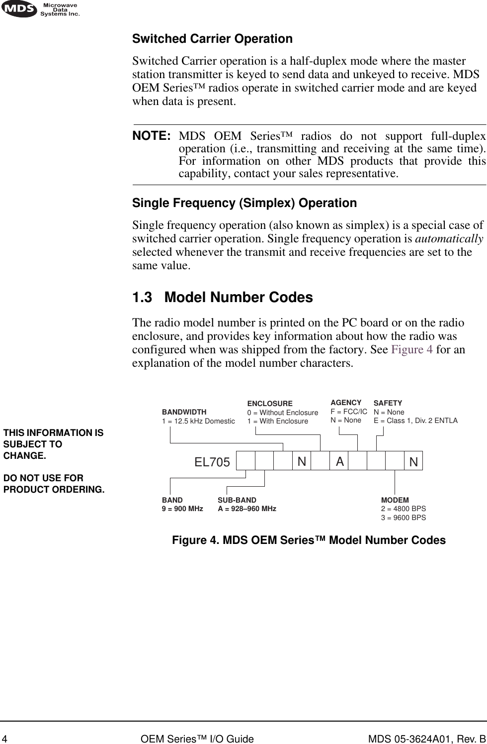
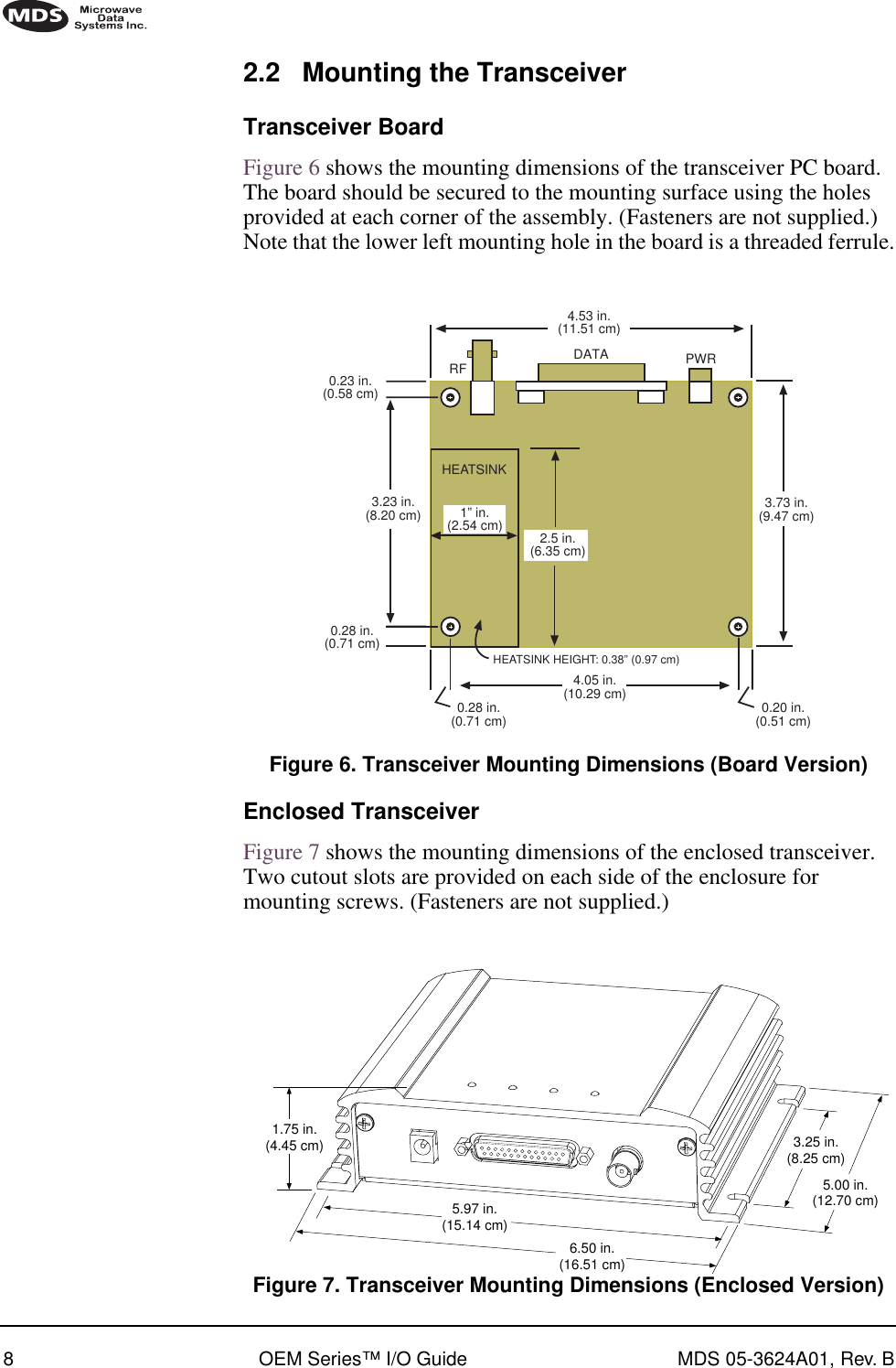
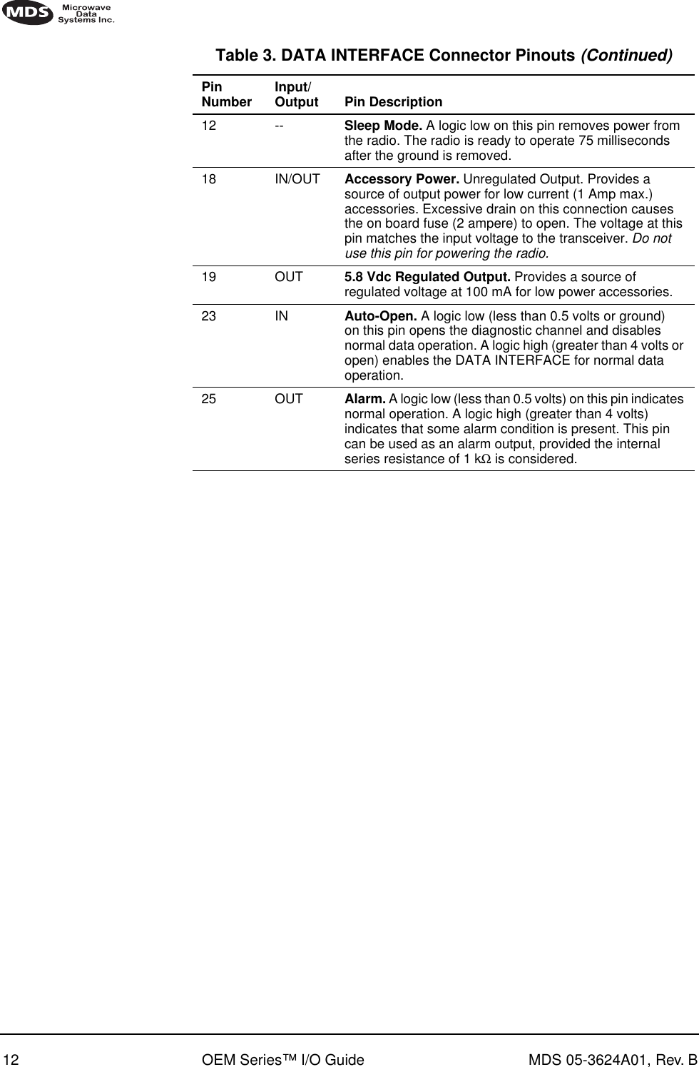
![MDS 05-3624A01, Rev. B OEM Series™ I/O Guide 17ACCESS DENIED—The command is unavailable to the user. Refer to the command descriptions for command information.EEPROM FAILURE— The INIT command was unable to write to EEPROM. This usually indicates a hardware error. Contact MDS for assistance.Table 5. Command summary Command name Function ADDR [NONE | 1–255]Details page 18 Set or display the network address of the radio. AMASK [0000 0000–FFFF FFFF]Details page 18Set or display hex code identifying which events trigger an alarm. BAUD [xxxxx abc]Details page 19 Set or display the DATA INTERFACE data rate and format. CTS [0–255]Details page 19 Set or display the Clear-to-Send delay in milliseconds. CTSHOLD [0–60000]Details page 19 Set or display the delay, in milliseconds, at the end of a CTS line response; CTS Key operation only. DEVICE [DCE | CTS KEY]Details page 20 Set or display the CTS options. DKEYDetails page 20 Dekey the radio (transmitter OFF) following a KEY command. INITDetails page 20 Set radio parameters to factory defaults. KEYDetails page 21 Key the radio (transmitter ON). Provides a carrier for testing. OWM [XXX...]Details page 21 Set or display the owner’s message. OWN [XXX...]Details page 21 Set or display the owner’s name. PWR [L | M | H]Details page 21 Set or display the transmit power setting. RSSI and RSSI!Details page 22 Display the Received Signal Strength Indication. RX [xxx.xxx]Details page 22 Set or display the receive frequency. RXTOT [NONE | 1–255]Details page 22 Set or display the value of the receive time-out timer. SERDetails page 22 Display the radio serial number. SREVDetails page 22 Display the software revision level.](https://usermanual.wiki/GE-MDS/DS-EL705-9.Operating-Instructions-Part-2-of-2/User-Guide-161471-Page-24.png)
![18 OEM Series™ I/O Guide MDS 05-3624A01, Rev. B4.4 Detailed Command DescriptionsThe only essential commands for most applications are transmit frequency (TX xxx.xxx), receive frequency (RX xxx.xxx), and network address (ADDR xxx). However, proper use of the additional commands allows you to tailor the transceiver for a specific use or conduct basic diagnostics on the radio. This section gives more detailed information for the user commands previously listed in Table 5.In many cases, the commands shown here can be used in two ways. First, you can type only the command name to view the currently programmed data. Secondly, you can set or change the existing data by typing the command, followed by a space, and then the desired entry. In the list below, allowable data values, if any, are shown in brackets following the command name. The separator symbol (|) indicates that you can enter one of the values in the list.ADDR [NONE | 1–255]The ADDR command displays or sets the network address of the radio. In order for all the radios in a network to communicate, their network addresses must be identical, or set to NONE. (The radio is shipped from the factory with ADDR set to NONE.)AMASK [0000 0000–FFFF FFFF]The AMASK (alarm mask) command displays or sets which events cause the alarm output signal to be active. Normally, the mask is FFFF FFFF, meaning that any of the 32 possible events activate the alarm output signal. No special configuration is required for typical applications.Entering the AMASK command alone displays the current setting of alarm events in hexadecimal format.Entering the AMASK command followed by an eight-digit hexadecimal number reprograms the specified events to trigger an alarm.Each bit that is a ‘1’ identifies an associated alarm condition that can trigger the alarm output status line. Each bit that is a ‘0’ treats the associated alarm as irrelevant when deciding whether or not to assert the alarm output status line. STATDetails page 22 Display the current alarm status. TOT [1–255 | ON | OFF]Details page 23 Set or display the time-out timer status and the timer delay in milliseconds. TX [xxx.xxx]Details page 23 Set or display the transmit frequency.Table 5. Command summary (Continued)Command name Function](https://usermanual.wiki/GE-MDS/DS-EL705-9.Operating-Instructions-Part-2-of-2/User-Guide-161471-Page-25.png)
![MDS 05-3624A01, Rev. B OEM Series™ I/O Guide 19Thus, an eight-digit hexadecimal number can classify up to 32 events as alarm triggers for the alarm output status line. See Table 6 on Page 25 for a list of the event codes and their hex values. The hex value of the mask is simply the sum of the hex values of the event codes corresponding to the alarm triggering events.BAUD [xxxxx abc]This command sets (or displays) the communication attributes for the DATA INTERFACE port.The first parameter (xxxxx) is baud rate. Baud rate is specified in bits-per-second (bps) and must be one of the following speeds: 1200, 2400, 4800, 9600, or 19200.The second parameter of the BAUD command (abc) is a three-character block indicating how the data is formatted:a = Data bits (7 or 8)b = Parity (N for None, O for Odd, E for Even)c = Stop bits (1 or 2)The factory default setting is 9600 baud, 8 data bits, no parity, 1 start bit, and 1 stop bit (Example: 9600 8N1).NOTE: 7N1, 8O2, and 8E2 are invalid communication settings and arenot supported by the transceiver.CTS [0–255]The CTS (clear-to-send) command sets or displays the timer value associated with the CTS line response. The command parameter ranges from 0 to 255 milliseconds.For DCE operation (see DEVICE command), the timer specifies how long to wait after the RTS line goes high, before the radio asserts CTS. A CTS value of zero asserts the CTS line immediately after the RTS line goes high.For CTS Key operation (see DEVICE command), the timer specifies how long to wait after asserting the CTS, before data becomes available. A timer value of zero means that data is available as soon as receivedCTSHOLD [0–60000]For CTS Key operation (see DEVICE command), the CTSHOLD command sets or displays the timer value associated with the end of a CTS line response. The timer value specifies the length of time that CTS remains active following the last byte from the RXD pin of the DATA INTERFACE port. The time is in milliseconds. The default value is 0, which means that CTS drops immediately after the last byte.](https://usermanual.wiki/GE-MDS/DS-EL705-9.Operating-Instructions-Part-2-of-2/User-Guide-161471-Page-26.png)
![20 OEM Series™ I/O Guide MDS 05-3624A01, Rev. BFor DCE operation (see DEVICE command), this command has no effect. The response CTSHOLD n/a is displayed.DEVICE [DCE | CTS KEY]The DEVICE command sets or displays the device behavior of the radio. The command parameter is either DCE or CTS KEY.The default selection is DCE. In this mode, CTS goes high following RTS, subject to the CTS programmable delay time. Hardware flow control is implemented by signaling the CTS line if data arrives faster than it can be buffered and transmitted. The transceiver does not require an RTS/CTS handshake. Data is transmitted whenever there is data to send.If CTS KEY is selected, the CTS line transforms to a Receive Data indicator (with programmable delays) in order to provide a control line for use by other devices. The RTS line is ignored. CTS is asserted immediately following the receipt of RF data, but data is not sent out the DATA INTERFACE port until the CTS programmable delay time has expired. (See CTSHOLD description for the delay available following the data.)A typical use of CTSKEY is to provide a keyline (or RTS signal) for a half-duplex modem or other radio.DKEYThis command deactivates the transmitter after it has been keyed with the KEY command.NOTE: The DKEY and KEY commands are not intended for normaloperation. They are tools for field testing and installation.INITThe INIT command is used to re-initialize the radio’s operating parameters to the factory defaults. This may be helpful when trying to resolve configuration problems that may have resulted from the entry of one or more improper command settings. Entry of this command allows you to get back to a known working state. The following changes to the radio are made when INIT is entered:•AMASK is set to FFFF FFFF•BAUD is set to 9600 baud, 8 data bits, no parity, and 1 stop bit (9600 8N1)•CTS is set to 0•CTSHOLD is set to 0•DEVICE is set to DCE](https://usermanual.wiki/GE-MDS/DS-EL705-9.Operating-Instructions-Part-2-of-2/User-Guide-161471-Page-27.png)
![MDS 05-3624A01, Rev. B OEM Series™ I/O Guide 21•PWR is set to H [+37 dBm (5 watts)]•RXTOT is set to NONE•TOT is set to OFFAll other commands stay at their previously established settings.KEYThis command activates the transmitter. The transmitter stays keyed until either the DKEY command is entered, or the transmitter time-out timer is enabled and times out. See also the DKEY and TOT commands.NOTE: The KEY and DKEY commands are not intended for normaloperation. They are tools for field testing and installation.OWM [XXX...]This is a command to display or set an owner’s message. To program the owner’s message, type OWM then the message, followed by . The maximum number of characters that can be entered is 30.To display the owner’s message, type OWM then . The owner’s message appears on the display.OWN [XXX...]This is a command to display or set an owner’s name. To program the owner’s name, type OWN then the name, followed by . The maximum number of characters that can be entered is 30.To display the owner’s name, type OWN then . The owner’s name appears on the display.PWR [L | M | H]NOTE: This function may not be available, depending on certificationrequirements for a particular region.This command displays or sets the desired RF forward output power setting of the radio. The PWR command parameter is specified as L (low), M (medium), or H (high). The default setting is H. The values of L, M, and H are:L = 24 dBm (250 mW)M = 30 dBm (1 W)H = 37 dBm (5 W)ENTERENTERENTERENTER](https://usermanual.wiki/GE-MDS/DS-EL705-9.Operating-Instructions-Part-2-of-2/User-Guide-161471-Page-28.png)
![22 OEM Series™ I/O Guide MDS 05-3624A01, Rev. BRSSI and RSSI!These commands continuously display the radio’s Received Signal Strength Indication (RSSI) in dBm units. Incoming signal strengths from –50 dBm to –120 dBm are displayed.The RSSI command causes display of received signal strength, updated once every second. Press to terminate the display.The RSSI! command displays a one-time reading of the RSSI at the diagnostic port.RX [xxx.xxx]This command sets or displays the radio’s receive frequency in MHz. The frequency must be an integer multiple of the step size and must be in the valid range. If the entered frequency is invalid, the terminal interface displays the message INCORRECT ENTRY.NOTE: The frequency must be in the valid range for the sub-bandpurchased, and may not be programmed “between” channels.RXTOT [NONE | 1–255]The RXTOT command sets or displays the receive time-out timer value in minutes. This timer triggers an alarm (event 12) if data is not detected within the specified time.Entering the RXTOT command without a parameter displays the timer value in minutes. Entering the RXTOT command with a parameter ranging from 1 to 255 resets the timer in minutes. Entering the RXTOT command with the parameter NONE disables the timer.SERThis command displays the radio’s serial number as recorded at the factory.SREVThis command displays the software revision level of the transceiver firmware.STATThis command displays the current alarm status of the transceiver.If no alarms exist, the message NO ALARMS PRESENT appears at the top of the terminal display.ENTER](https://usermanual.wiki/GE-MDS/DS-EL705-9.Operating-Instructions-Part-2-of-2/User-Guide-161471-Page-29.png)
![MDS 05-3624A01, Rev. B OEM Series™ I/O Guide 23If an alarm does exist, a two-digit code (00–31) is displayed and the alarm is identified as MAJOR or MINOR. A brief description of the alarm code is also given. Detailed descriptions of event codes are provided in Table 6 on Page 25.If more than one alarm exists, the word MORE appears at the bottom of the screen and additional alarms are viewed by pressing the key. Alarms are displayed in ascending order, major alarms before minor ones.TOT [1–255 | ON | OFF]This command sets or displays the transmitter time-out timer value (1–255 seconds), as well as the timer status (ON or OFF). The command parameter can be either the timer value or the status, but not both. The parameter ON enables the timer; OFF disables the timer.If the timer is on, and the radio remains keyed for a longer duration than the TOT value, the transmitter is automatically unkeyed. When this happens, the radio must be commanded back to an unkeyed state before a new keying command is accepted.By default the timer is ON and set to 30 seconds.TX [xxx.xxx]This command sets or displays the radio’s transmit frequency in MHz. The frequency must be an integer multiple of the step size and must be in the valid range. If the entered frequency is invalid, the terminal interface displays the message INCORRECT ENTRY.NOTE: The frequency must be in the valid range for the sub-bandpurchased, and may not be programmed “between” channels.ENTER](https://usermanual.wiki/GE-MDS/DS-EL705-9.Operating-Instructions-Part-2-of-2/User-Guide-161471-Page-30.png)