GE MDS DS-EL805 MDS TransNet 900 User Manual users manual addendum
GE MDS LLC MDS TransNet 900 users manual addendum
GE MDS >
Contents
- 1. users manual addendum
- 2. User Manual Addendum
- 3. user manual
users manual addendum

MDS 05-2708A01, Rev. A Page 1 of 2
MDS TransNET 900 Transceiver
ADDENDUM
Addendum to MDS 05-2708A01, Rev. A April 19, 2002
Microwave Data Systems Inc., 175 Science Parkway, Rochester, NY 14620 U.S.A.
General Business +1 (585) 242-9600, FAX +1 (585) 242-9620
This addendum contains corrections and additions to the MDS TransNET 900 Installation Guide (MDS P/N 05-
2708A01, Rev. A) published in March 2002. The Bolded text below indicates new or revised material. You may
wish to make these pen & ink changes directly to your manual or include a reference to this addendum in the
appropriate sections.
ITEM 1—Command Changes
Page 19, Data Buffer Setting: Default setting is OFF.
Page 25, BUFF [ON, OFF]: Default setting is OFF.
Page 26, CTSHOLD [0-6000]: Should read CTSHOLD [0-60000].
Page 28, RSSI description: Change reference to minimum output range from “-50 dBm” to “-40 dBm.”
Page 30, SKIP [NONE, 1…8] description: Delete text reference to “128 frequency.”
Page 31, TX [xxxx] description: Default Transmit Frequencies are Master—902.200 MHz, Remote—927.800
MHz.
ITEM 2—Table 8. Alarm Codes, Page 34
For Alarm Code 30, delete second sentence that reads “Bit errors are likely to be present in the data.”
ITEM 3—Internal Fuse Replacement, Page 35
Reverse polarity will not cause the fuse to blow.
ITEM 4—Technical Specifications, Page 38
Change Temperature Range from “-30C to +60C” to “-40 to +70C.”
Change Current Draw (Receive) rating from “125 mA @ 13.8 Vdc” to “100 mA @ 13.8 Vdc.”
Delete “TTL/” reference.
Change Data Latency from “10 ms typical” to “7 ms typical.”
ITEM 5—Table 10. Data connector pin descriptions—RS/EIA-232, Page 40
Delete entire text description for Pin 9 and replace with “Not Used.”
ITEM 6— Table 11. Data connector pin descriptions—RS/EIA-232, Page 41
Change table title to “Data connector pin descriptions—RS/EIA-485.”
In Pin 2 description, change heading from “RXD/Y” to “RXD/+.” Also, replace the words “Non-inverted driver
output” with “non-inverted receive data.”
In Pin 3 description, change heading from “TXD/A” to “TXD/+.” Also, replace the words “Non-inverted receiver
input” with “non-inverted transmit data”
Page 2 of 2 MDS 05-2708A01, Rev. A
In Pin 7 description, change heading from “RTS/B—Request-to-Send” to “TXD/-.” Also, replace the words
“Inverted receiver input” with “Inverted transmit data.”
In Pin 8 description, change heading from “CTS/Z—Clear-to-Send” to “RXD/-.” Also, delete all descriptive text
and replace with “Inverted receive data.”
ITEM 7— New PORT Command
The transceiver’s DATA port configuration (RS-232 or RS-485) may be read by entering the PORT command. The
port may be configured for RS-232 or RS-485 operation using the following commands:
PORT RS232—RS-232 operation
PORT RS485—RS-485 operation
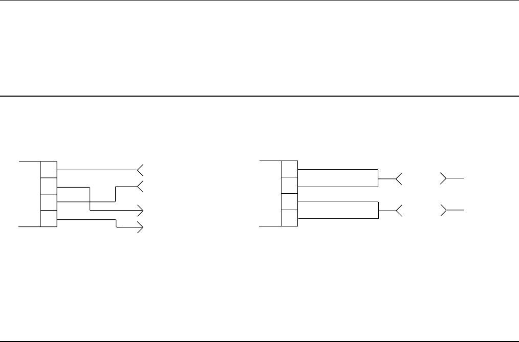
ITEM 8— Wiring for RS-485 systems
When wiring the transceiver’s DATA connector for RS-485 2-wire or 4-wire operation, use one of the following
arrangements :
TXD/+
RXD/+
2
3
7
DATA CONNECTOR
8
RXD/-
TXD/-
4-WIRE CONNECTIONS
RX/TX+
2
3
7
DATA CONNECTOR
8
2-WIRE CONNECTIONS
RX/TX-
ITEM 9— Antenna & Feedline Selection, Page 9
Currently, the transceiver is only authorized for use in the USA with an MDS Clearwave antenna, Part Number
97-3662A13 and a 3-meter feedline. Check with MDS for the status on additional approvals that are pending.
End of Document