GE MDS DS-EL805 MDS TransNet 900 User Manual users manual addendum
GE MDS LLC MDS TransNet 900 users manual addendum
UserManual.wiki
>
GE MDS
>
DS-EL805 User Manual
>
users manual addendum
Contents
1.
users manual addendum
2.
User Manual Addendum
3.
user manual
users manual addendum
Navigation menu
Upload a User Manual
Namespaces
Wiki Guide
HTML
PDF
Info
Views
User Manual
Discussion / Help
Navigation
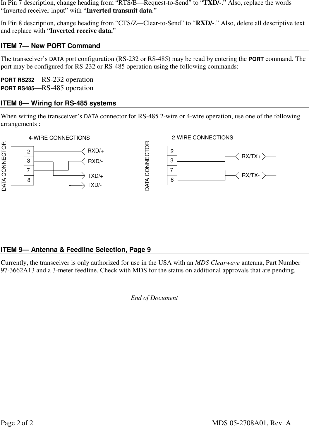
![MDS 05-2708A01, Rev. A Page 1 of 2MDS TransNET 900 TransceiverADDENDUMAddendum to MDS 05-2708A01, Rev. A April 19, 2002Microwave Data Systems Inc., 175 Science Parkway, Rochester, NY 14620 U.S.A.General Business +1 (585) 242-9600, FAX +1 (585) 242-9620This addendum contains corrections and additions to the MDS TransNET 900 Installation Guide (MDS P/N 05-2708A01, Rev. A) published in March 2002. The Bolded text below indicates new or revised material. You maywish to make these pen & ink changes directly to your manual or include a reference to this addendum in theappropriate sections.ITEM 1—Command ChangesPage 19, Data Buffer Setting: Default setting is OFF.Page 25, BUFF [ON, OFF]: Default setting is OFF.Page 26, CTSHOLD [0-6000]: Should read CTSHOLD [0-60000].Page 28, RSSI description: Change reference to minimum output range from “-50 dBm” to “-40 dBm.”Page 30, SKIP [NONE, 1…8] description: Delete text reference to “128 frequency.”Page 31, TX [xxxx] description: Default Transmit Frequencies are Master—902.200 MHz, Remote—927.800MHz.ITEM 2—Table 8. Alarm Codes, Page 34For Alarm Code 30, delete second sentence that reads “Bit errors are likely to be present in the data.”ITEM 3—Internal Fuse Replacement, Page 35Reverse polarity will not cause the fuse to blow.ITEM 4—Technical Specifications, Page 38Change Temperature Range from “-30C to +60C” to “-40 to +70C.”Change Current Draw (Receive) rating from “125 mA @ 13.8 Vdc” to “100 mA @ 13.8 Vdc.”Delete “TTL/” reference.Change Data Latency from “10 ms typical” to “7 ms typical.”ITEM 5—Table 10. Data connector pin descriptions—RS/EIA-232, Page 40Delete entire text description for Pin 9 and replace with “Not Used.”ITEM 6— Table 11. Data connector pin descriptions—RS/EIA-232, Page 41Change table title to “Data connector pin descriptions—RS/EIA-485.”In Pin 2 description, change heading from “RXD/Y” to “RXD/+.” Also, replace the words “Non-inverted driveroutput” with “non-inverted receive data.”In Pin 3 description, change heading from “TXD/A” to “TXD/+.” Also, replace the words “Non-inverted receiverinput” with “non-inverted transmit data”](https://usermanual.wiki/GE-MDS/DS-EL805.users-manual-addendum/User-Guide-238073-Page-1.png)