GE MDS DS-ENETL2TU ENET-L2TU 40 watt amplifier User Manual GE MDS TD220 Manual
GE MDS LLC ENET-L2TU 40 watt amplifier GE MDS TD220 Manual
UserManual.wiki
>
GE MDS
>
DS-ENETL2TU User Manual
>
Users Manual
Contents
1.
Manual
2.
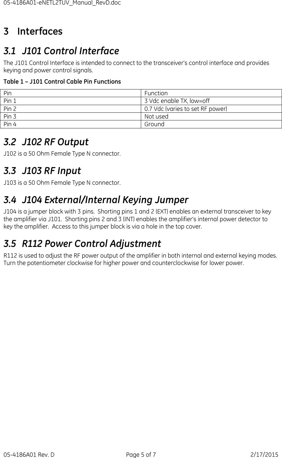
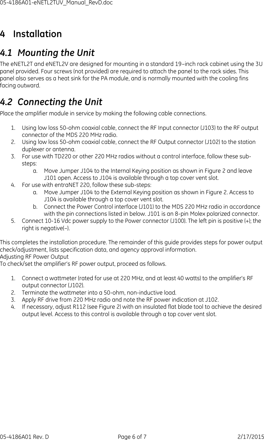
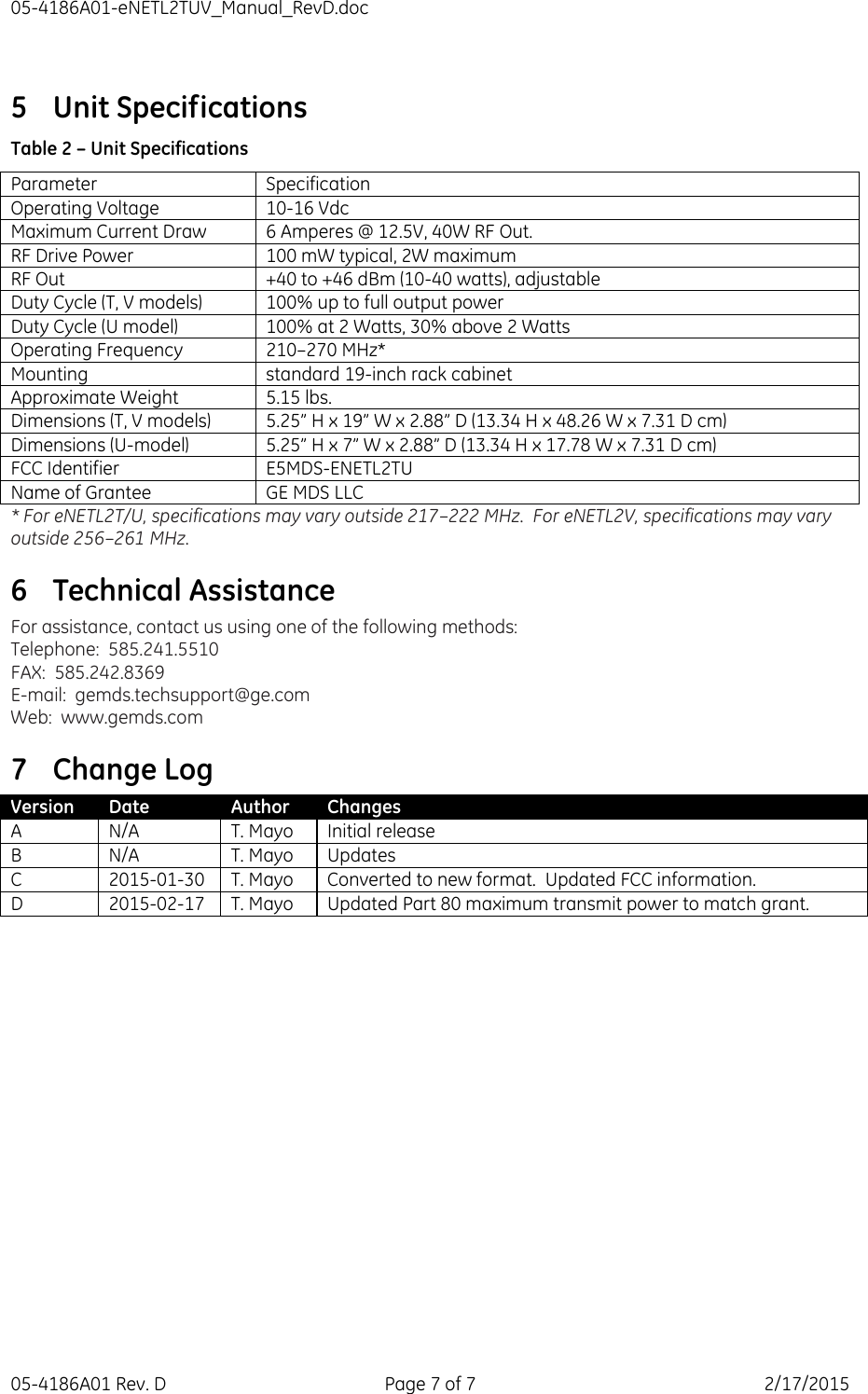
Users Manual
Users Manual
Navigation menu
Upload a User Manual
Namespaces
Wiki Guide
HTML
PDF
Info
Views
User Manual
Discussion / Help
Navigation