GE MDS DS-GPA-1 40 Watt RF Amplifier User Manual GPA 1manual RevA 5 2 16 3
GE MDS LLC 40 Watt RF Amplifier GPA 1manual RevA 5 2 16 3
GE MDS >
Users Manual
GPA-1 manual
GEMDSGPA‐1Manual
P/Ndraft
RevA.
GPA-1 manual
TableofContents
1Important Information ............................................................................................................ 3
1.1RF Exposure ................................................................................................................... 3
1.2FCC Approval Notice ...................................................................................................... 3
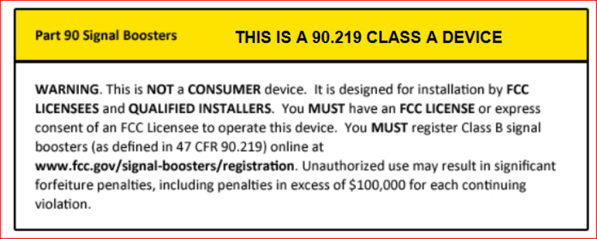
1.3FCC Part 90 Information ................................................................................................. 3
1.4Product Description ........................................................................................................ 4
1.5Power Control Loop ........................................................................................................ 4
2Interfaces .............................................................................................................................. 5
2.1J101 Control Interface .................................................................................................... 5
2.2J102 RF Output .............................................................................................................. 5
2.3J103 RF Input ................................................................................................................. 5
2.4J104 External/Internal Jumper ........................................................................................ 5
2.5R112 Power Control Adjustment .................................................................................... 6
3Installation ............................................................................................................................. 6
3.1Mounting the Unit ........................................................................................................... 6
3.2Connecting the Unit ........................................................................................................ 6
3.3 Alignment (Setting power output) ...................................................................................... 6
GPA-1B smaller heat-sink option ................................................................................................ 7
GPA-1 standard heat-sink option ................................................................................................ 7
Unit Specifications ....................................................................................................................... 8
4Technical Assistance ............................................................................................................ 8
5Change Log ........................................................................................................................... 8

GPA-1 manual
1 ImportantInformation
1.1 RFExposure
Professional installation required. The radio equipment described in this guide emits radio
frequency energy. Although the power level is low, the concentrated energy from a directional
antenna may pose a health hazard.
Do not allow people to come closer than 1.8 meters, (5.9 feet) to the antenna when the
transmitter is operating with a unity gain antenna.
This is an RF amplifier, the maximum ERP for this FCC band is 500 watts, this equates to an RF
safety distance of 5.7 meters. For Canada, the maximum ERP is 125 Watts, this equates to a
distance of 3.6 meters.
Please consult the FCC website below for RF safety distances, using different antenna gain
configurations which affect the ERP.
More information on RF exposure can be found on the Internet at:
www.fcc.gov/oet/info/documents/bulletins.
Installation professionnelle requise. L'équipement radio décrite dans ce guide émet de l'énergie
de fréquence radio. Bien que le niveau de puissance est faible, l'énergie concentrée depuis une
antenne directionnelle peut-être poser un danger pour la santé.
Ne laissez pas les gens à se rapprocher de 1,8 mètres, (5,9 pieds) à l'antenne lorsque l'émetteur
fonctionne avec une antenne à gain unité.
Il s'agit d'un amplificateur RF, la P.A.R. maximale pour cette bande de FCC est de 500 watts,
cela équivaut à une distance de sécurité RF de 5,7 mètres. Pour le Canada, la P.A.R. maximale
est de 125 Watts, cela équivaut à une distance de 3,6 mètres.
Veuillez consulter le site de FCC ci-dessous pour les distances de sécurité RF, à l'aide de
configurations de gain antenne différentes qui affectent l'ERP.
Plus d'informations sur l'exposition aux radiofréquences se trouvent à l'adresse Internet :
www.fcc.gov/oet/info/documents/bulletins.
1.2 FCCApprovalNotice
ThisdeviceisofferedasalicensedAmplifierperFCCPart,90.Itisapprovedforuseunderthefollowing
conditions:ChangesormodificationsnotexpresslyapprovedbyGEMDSwillvoidtheuser’sauthorityto
operatetheequipment.
1.3 FCCPart90Information
ForFCCPart90,validfrequenciesare150‐174MHzatupto500WattsERP
GPA-1 manual
Caution; only use authorized antennas that meet the FCC license requirements.
Use of unauthorized antennas, cables, and/or coupling devices not conforming
with ERP/EIRP for outdoor/indoor will void the licensee’s license to operate.
Introduction
TheGPA‐1isanRFpoweramplifierdesignedforuseinthe150‐174MHzfrequencyrangeatupto40
Watts.Itisintendedtoserveasa100%dutycycleamplifierforMDSSD1operatinginpoint‐to‐multipoint
repeaterorbaseapplications.
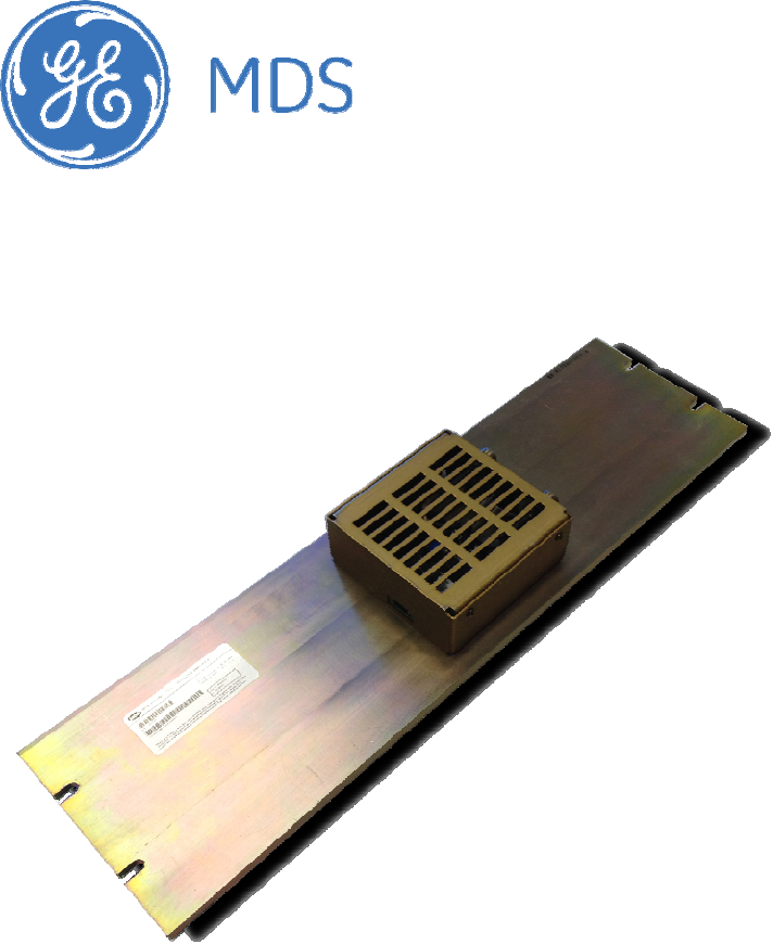
1.4 ProductDescription
TheGPA‐1poweramplifierconsistsofanRFamplifierandPCBmountedtoaheatsink,withaDCPower
interface,powercontrolinterface,andinput/outputRFconnectionsonthesidewallsofthechassis.DC
powerissuppliedtotheamplifierfromaregulatedandfilteredDCsourcecapableofsupplying10‐16Vdc
atamaximumcurrentof8Amperes.TheDCpowersourceshouldbecurrentlimitedorhaveaprotective
fuseorcircuitbreaker.
1.5 PowerControlLoop
TheGPA‐1amplifieroperatesinINTmode.InInternalmode,afeedbackcircuitwithintheamplifier
controlstheoutputpower.ThesetpointissetbypotentiometerR112,locatedwithintheamplifier.
Further,thePAperformsTX/RXswitchingtoprovidealowlossreceivepathwhennottransmitting.The
TX/RXcontrolisperformedbyRFdetectionwithinthePA.
GPA-1 manual
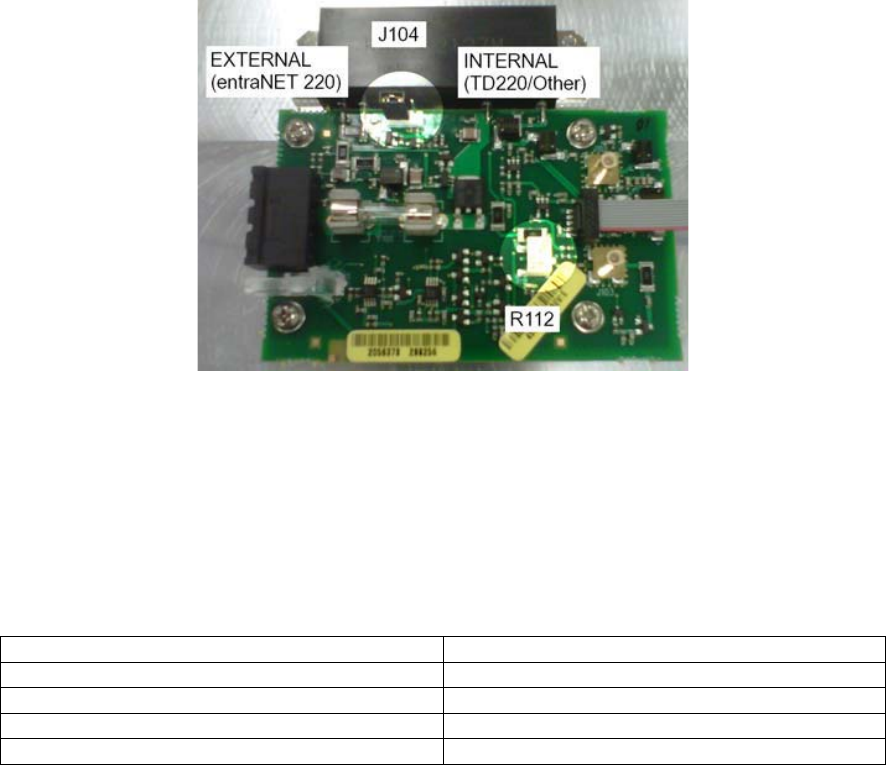
Figure1–J104andR112Locations
2 Interfaces
2.1 J101ControlInterface
TheJ101ControlInterfaceisintendedtoconnecttothetransceiver’scontrolinterfaceandprovides
keyingandpowercontrolsignals.
Table1–J101ControlCablePinFunctions
PinFunction
Pin13VdcenableTX,low=off
Pin20.7Vdc(variestosetRFpower)
Pin3Notused
Pin4Ground
2.2 J102RFOutput
J102isa50OhmFemaleTypeNconnector.
2.3 J103RFInput
J103isa50OhmMaleTypeN,REVERSEPolarityconnector.ThisRFampisprovidedwithaReverse
PolarityNconnector,tomeettheFCCRFsignalBooster/Amplifierrules.Theconnectorisprovidedsothat
onlyoneRFsignalcanbeinputtotheRFAmp.
ThisamplifierisdesignedtobeonlyusedwiththeGEMDSSD1DataTransceiver.
AtnotimeshallthisamplifierbeusedwithnomorethantheintendedsingleRFinput,anyother
combinationofsignalshallvoidtheFCCtypeapprovalofthisamplifier
2.4 J104External/InternalJumper
J104isajumperblockwith3pins.Shortingpins1and2(EXT)isnotusedfortheGPA‐1.Shortingpins2
and3(INT)enablestheamplifier’sinternalpowerdetectortocontroltheamplifierpoweroutput.Access
tothisjumperblockisviaaholeinthetopcover.
GPA-1 manual
2.5 R112PowerControlAdjustment
R112isusedtoadjusttheRFpoweroutputoftheamplifierininternalandmode.Turnthepotentiometer
clockwiseforhigherpowerandcounterclockwiseforlowerpower.
3 Installation
3.1 MountingtheUnit
TheGPA‐1isdesignedformountinginastandard19–inchrackcabinetusingthe3Upanelprovided.Four
screws(notprovided)arerequiredtoattachthepaneltotheracksides.Thispanelalsoservesasaheat
sinkforthePAmodule,andisnormallymountedwiththecoolingfinsfacingoutward.
3.2 ConnectingtheUnit
Placetheamplifiermoduleinservicebymakingthefollowingcableconnections.
1. Usinglowloss50‐ohmcoaxialcable,connecttheRFInputconnector(J103)totheRFoutput
connectoroftheMDSSD1radio.
2. Usinglowloss50‐ohmcoaxialcable,connecttheRFOutputconnector(J102)tothestation
duplexerorantenna.
3. ForusewithSD1transceiverfollowthesesub‐steps,PWRsetbetween23‐27dBm(inputpower).
Donotuseabove27dBmforGPA‐1input.MoveJumperJ104totheInternalKeyingpositionas
showninFigure1AccesstoJ104isavailablethroughatopcoverventslot.
4. Connect10‐16VdcpowersupplytothePowerconnector(J100).Theleftpinispositive(+);the
rightisnegative(–).
3.3Alignment(Settingpoweroutput)
AdjustingRFPowerOutput
Tocheck/settheamplifier’sRFpoweroutput,proceedasfollows.
1. Connectawattmeter(ratedforuseat150MHz,andatleast40watts)totheamplifier’sRF
outputconnector(J102).
2. Terminatethewattmeterintoa50‐ohm,non‐inductiveload.
3. SetSD1PWR=23dBm
4. ApplyRFdrivefrom150MHzradioandnotetheRFpowerindicationatJ102.
5. Ifnecessary,adjustR112(seeFigure2)withaninsulatedflatbladetooltoachievethedesired
outputlevel.Accesstothiscontrolisavailablethroughatopcoverventslot.
GPA-1 manual
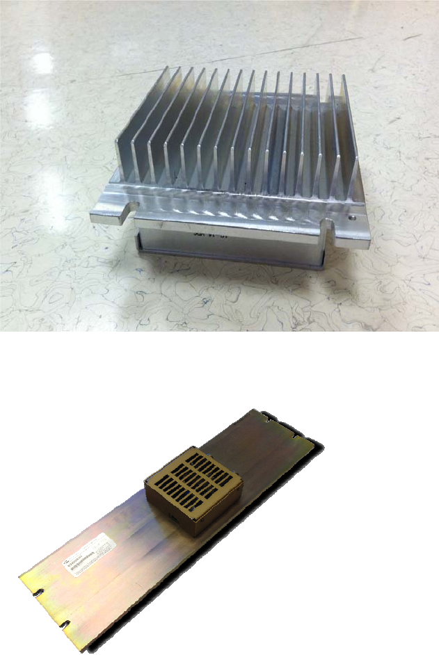
GPA‐1Bsmallerheat‐sinkoption
GPA‐1standardheat‐sinkoption

GPA-1 manual
UnitSpecifications
Table2–UnitSpecifications
ParameterSpecification
OperatingVoltage10‐16Vdc
MaximumCurrentDraw8Amperes@12.5V,40WRFOut.
RFDrivePowerSD1PWR=23dBm
RFOut+40to+46dBm(10‐40watts),adjustable
DutyCycle(GPA‐1model)100%uptofulloutputpower
DutyCycle(GPA‐1Bmodel)100%at2Watts,30%above2Watts
OperatingFrequency150
–
174 MHz*
Mountingstandard19‐inchrackcabinet
ApproximateWeight5.15lbs.
Dimensions(GPA‐1model)5.25”Hx19”Wx2.88”D(13.34Hx48.26Wx7.31Dcm)
Dimensions(GPA‐1B‐model)5.25”Hx7”Wx2.88”D(13.34Hx17.78Wx7.31Dcm)
FCCIdentifierE5MDS‐GPA‐1
NameofGranteeGEMDSLLC
4 TechnicalAssistance
Forassistance,contactususingoneofthefollowingmethods:
Telephone:585.241.5510
FAX:585.242.8369
E‐mail:gemds.techsupport@ge.com
Web:www.gemds.com
5 ChangeLog
VersionDateAuthorChanges
A D.McCarthy Initialrelease