GE MDS DS-GPA-9 RF Amplifier User Manual GE MDS TD220 Manual
GE MDS LLC RF Amplifier GE MDS TD220 Manual
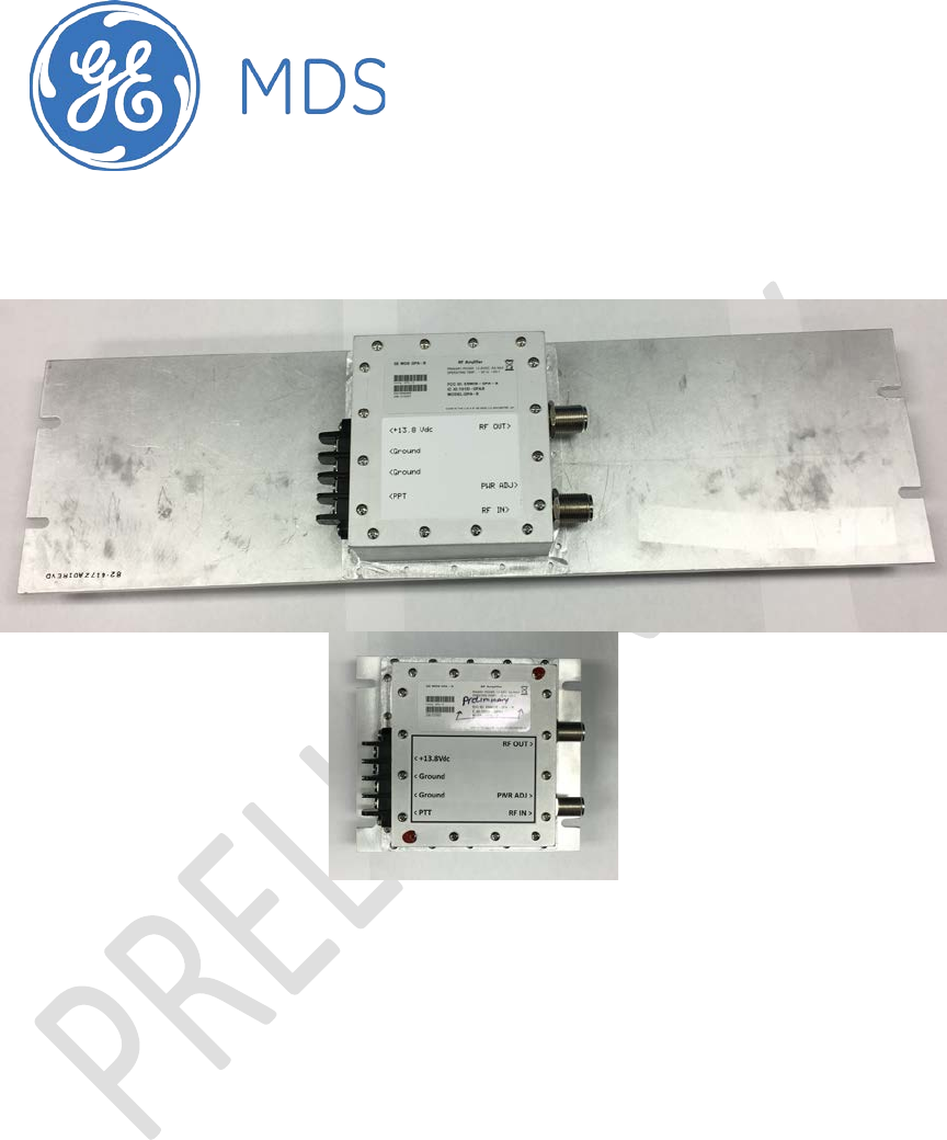
GE MDS >
Users Manual
GPA-9 manual
GE MDS GPA-9 Manual
P/N draft
Rev D.

GPA-9 manual
Table of Contents
1 Important Information ............................................................................................................ 3
1.1 RF Exposure ................................................................................................................... 3
1.2 FCC Approval Notice ...................................................................................................... 3
1.3 FCC Part 90 Information ................................................................................................. 3
1.4 Product Description ........................................................................................................ 4
1.5 Power Control Loop ........................................................................................................ 4
Interfaces ..................................................................................................................................... 5
1.6 J102 Terminal Block ....................................................................................................... 5
1.7 J100 RF Output .............................................................................................................. 5
1.8 J101 RF Input ................................................................................................................. 5
1.9 R138 Power Control Adjustment .................................................................................... 5
1.10 LED Indicators ................................................................................................................ 5
2 Installation ............................................................................................................................. 6
2.1 Mounting the Unit ........................................................................................................... 6
2.2 Connecting the Unit ........................................................................................................ 6
3.3 Alignment (Setting power output) ...................................................................................... 6
3.4 Overtemperature Fault ....................................................................................................... 6
3.5 VSWR Fault ....................................................................................................................... 6
GPA-9B smaller heat-sink option ................................................................................................ 7
GPA-9 standard heat-sink option ................................................................................................ 7
Unit Specifications ....................................................................................................................... 8
3 Technical Assistance ............................................................................................................ 8
4 Change Log ........................................................................................................................... 8

GPA-9 manual
1 Important Information
1.1 RF Exposure
Professional installation required. The radio equipment described in this guide emits radio frequency
energy. Although the power level is low, the concentrated energy from a directional antenna may pose a
health hazard.
Do not allow people to come closer than 1.12 meters, (3.7 feet) to the antenna when the transmitter is
operating with a unity gain antenna.
This is an RF amplifier, the maximum ERP for this FCC band is 500 watts, this equates to an RF safety
distance of 3.82 meters.
Please consult the FCC website below for RF safety distances, using different antenna gain configurations
which affect the ERP.
More information on RF exposure can be found on the Internet at:
www.fcc.gov/oet/info/documents/bulletins.
1.2 FCC Approval Notice
This device is offered as a licensed Amplifier per FCC Part, 90. It is approved for use under the following
conditions: Changes or modifications not expressly approved by GE MDS will void the user’s authority to
operate the equipment.
1.3 FCC Part 90 Information
For FCC Part 90, valid frequencies are 896-940 MHz at up to 500 Watts ERP
Caution; Only use authorized antennas that meet the FCC license requirements.
Use of unauthorized antennas, cables, and/or coupling devices not conforming
with ERP/EIRP for outdoor/indoor will void the licensee’s license to operate.
WARNING: This is NOT a CONSUMER device. It is designed for installation by an installer
approved by an ISED licensee. You MUST have an ISED LICENCE or the express consent of an
ISED licensee to operate this device.
AVERTISSEMENT: ce n'est PAS un appareil CONSOMMATEUR. Il est conçu pour être installé
par un installateur approuvé par un titulaire de licence ISED. Vous devez avoir une LICENCE
ISED ou le consentement exprès d'un titulaire de licence ISED pour utiliser cet appareil.
GPA-9 manual
Introduction
The GPA-9 is an RF power amplifier designed for use in the 896-940MHz frequency range at up to 40
Watts. The A version is intended to serve as a 100% duty cycle amplifier for MDS SD9 and other MDS
radios operating in point-to-multipoint repeater or base applications.
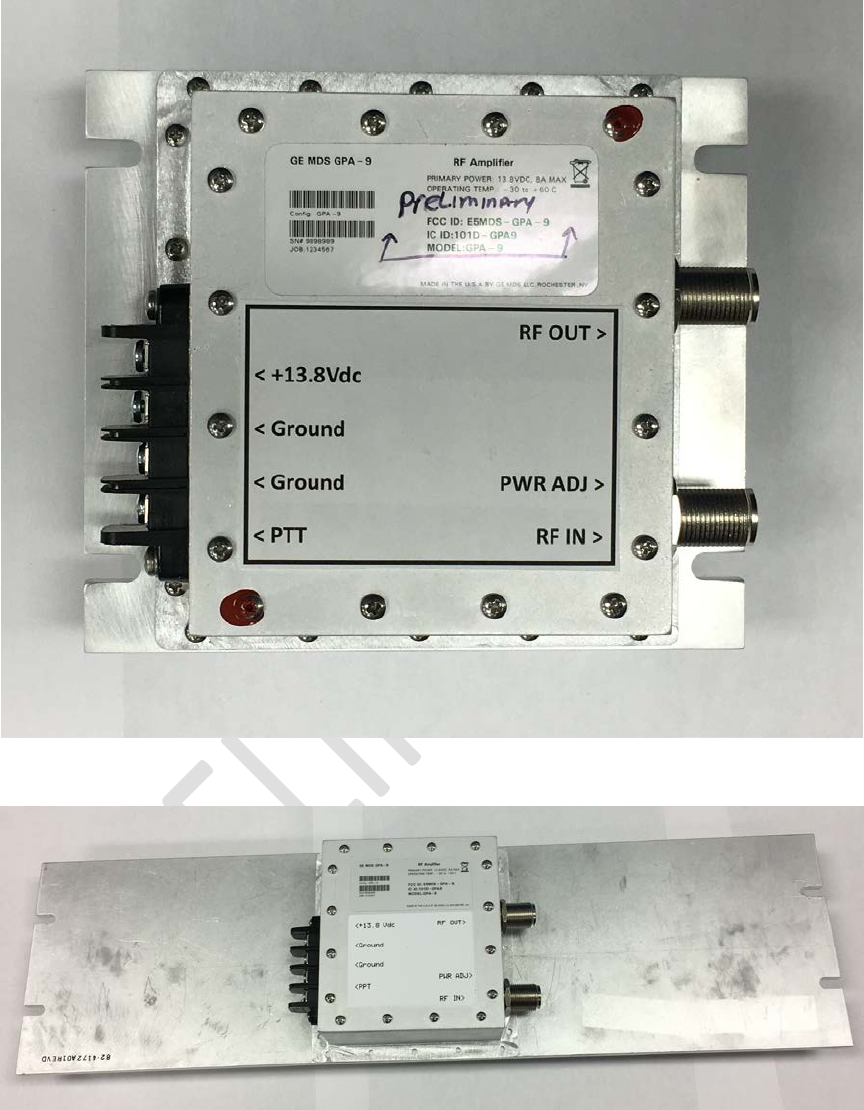
1.4 Product Description
The GPA-9 power amplifier consists of an RF amplifier and PCB mounted to a heat sink, with a DC Power
interface, PTT and input/output RF connections on the sidewalls of the chassis. DC power is supplied to
the amplifier from a regulated and filtered DC source capable of supplying 10-16 Vdc at a maximum
current of 10 Amperes. The DC power source should be current limited or have a protective fuse or circuit
breaker.
1.5 Power Control Loop
The GPA-9 amplifier uses a feedback circuit within the amplifier to control the output power. The set
point is set by potentiometer R138, accessed near the RF input connector.
Further, the PA performs TX/RX switching to provide a low loss receive path when not transmitting. The
TX/RX control is performed by RF detection within the PA. There is also a PTT (Push to Transmit) input on
the terminal strip.
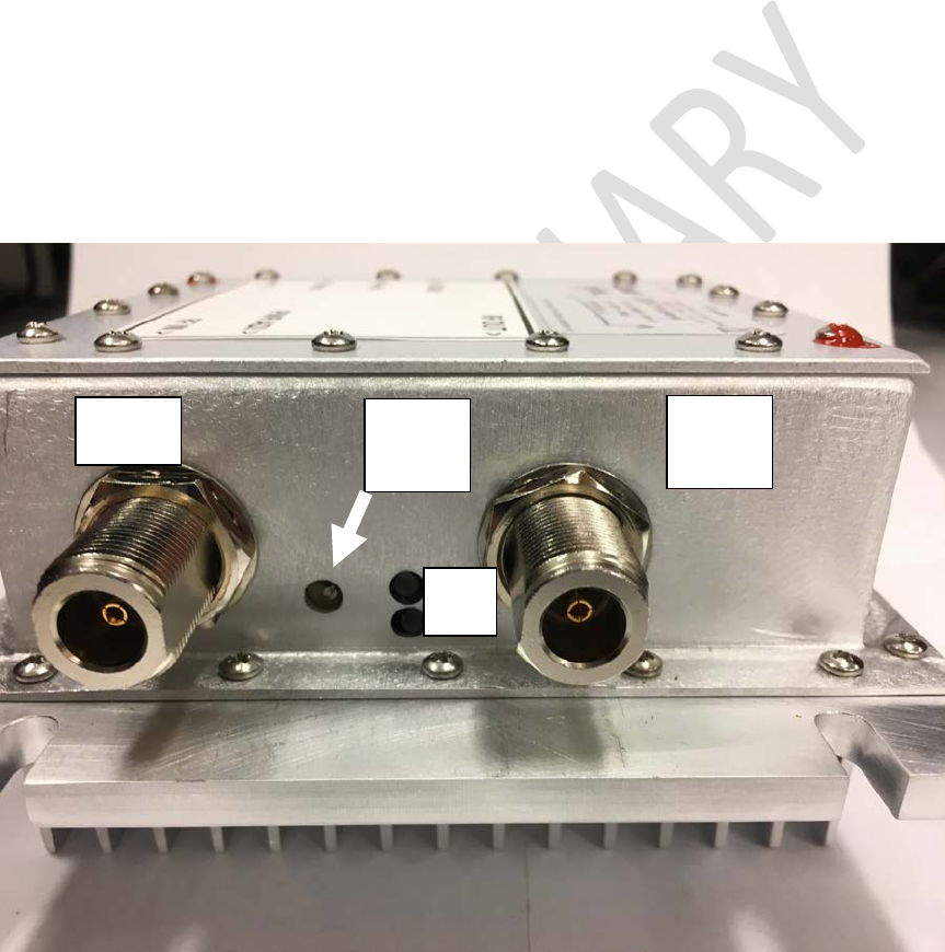
Figure 1 – R138 Location
Power
Control
R138
RF IN
J101
RF
OUT
J100
TX
RX
GPA-9 manual
Interfaces
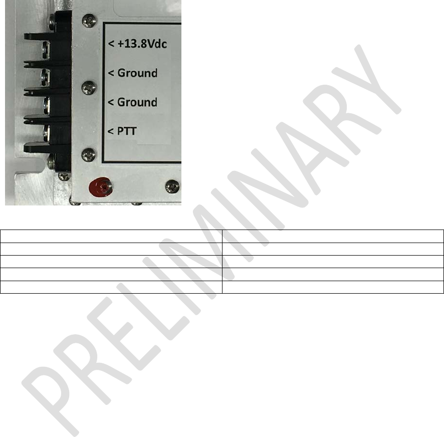
1.6 J102 Terminal Block
The J102 terminal block provides keying and power control signals.
Table 1 – J102 Control Cable Pin Functions
Pin
Function
Pin 1
13.8V nominal 10 amps DC input
Pin 2
Power supply Ground
Pin 3
ground
Pin 4
PTT (ground to transmit)
1.7 J100 RF Output
J100 is a 50 Ohm Female Type N connector.
1.8 J101 RF Input
J101 is a 50 Ohm Female Type N connector.
1.9 R138 Power Control Adjustment
R138 is used to adjust the RF power output of the amplifier in internal and mode. Turn the potentiometer
clockwise for higher power and counterclockwise for lower power. RF output power will depend on power
supply voltage (10-16V DC) and RF drive level (+27 to +30dBm)
1.10 LED Indicators
A pair of LED indicators are located next to the Power Adjustment. The lower indicator (GREEN) will
indicate that DC power is applied and the PA is in the receive state. The upper indicator (RED) will indicate
that the PA is in the transmit state. If both are on it indicates an Overtemperature fault. (See section 3.4)

GPA-9 manual
2 Installation
2.1 Mounting the Unit
The GPA-9 A version is designed for mounting in a standard 19–inch rack cabinet using the 3U panel
provided. Four screws (not provided) are required to attach the panel to the rack sides. This panel also
serves as a heat sink for the PA module, and is normally mounted with the cooling fins facing outward.
The GPA-9 B version uses a smaller heatsink (intermittent duty) but has the same 4 mounting screws.
2.2 Connecting the Unit
Place the amplifier module in service by making the following cable connections.
1. Using low loss 50-ohm coaxial cable, connect the RF Input connector (J101) to the RF output
connector of the MDS SD9 radio.
2. Using low loss 50-ohm coaxial cable, connect the RF Output connector (J100) to the station
duplexer or antenna.
3. Connect 10-16 Vdc power supply (13.8V nominal) to the Power connector (J102). The outside pin
is positive (+); the next is negative (–).
3.3 Alignment (Setting power output)
Adjusting RF Power Output
To check/set the amplifier’s RF power output, proceed as follows.
1. Connect a wattmeter (rated for use at 900 MHz, and at least 40 watts) to the amplifier’s RF
output connector (J102).
2. Terminate the wattmeter into a 50-ohm, non-inductive load.
3. Set SD9 PWR=30dBm. (+27 to +30dBm is allowed)
4. Apply RF drive from 900 MHz radio and note the RF power indication at J100.
5. If necessary, adjust R138 (see Figure 2) with an insulated flat blade tool to achieve the desired
output level. Access to this control is available near the RF input connector
3.4 Overtemperature Fault
If the flange temperature of the active device in the PA exceeds recommended limits (90C) the PA bias will
be automatically removed reducing output power. At this time the GREEN LED will be ON at the same
time as the RED LED when the unit is in transmit. When temperature falls within limits normal operation
will return.
3.5 VSWR Fault
GPA-9 will automatically reduce output power if a high VSWR is detected.
GPA-9 manual
GPA-9B smaller heat-sink option
GPA-9 standard heat-sink option
GPA-9 manual
Unit Specifications
Table 2 – Unit Specifications
Parameter
Specification
Operating Voltage
10-16 Vdc. 13.8V nominal
Maximum Current Draw
10 Amperes @ 13.8V, 40W RF Out.
RF Drive Power
SD9 PWR=30dBm
RF Out
+40 to +46 dBm (10-40 watts), adjustable
Duty Cycle (GPA-9A model)
100% up to full output power
Duty Cycle (GPA-9B model)
30% above 10 Watts
Operating Frequency
896-940 MHz
Mounting
standard 19-inch rack cabinet
Approximate Weight
5.15 lbs.
Dimensions (GPA-9A model)
5.25” H x 19” W x 2.88” D (13.34 H x 48.26 W x 7.31 D cm)
Dimensions (GPA-9B model)
5.25” H x 7” W x 2.88” D (13.34 H x 17.78 W x 7.31 D cm)
FCC Identifier
E5MDS-GPA-9
Name of Grantee
GE MDS LLC
3 Technical Assistance
For assistance, contact us using one of the following methods:
Telephone: 585.241.5510
E-mail: gemds.techsupport@ge.com
Web: www.gemds.com
4 Change Log
Version
Date
Author
Changes
A
D.McCarthy
Initial release
B
5/5/17
T Hodge
Corrections for FCC filing
C
5/15/17
T Mayo
Corrected nomenclature for GPA-9A and GPA-9B