GE MDS DS-LCT450 Tri-Mode Data Transceiver User Manual 4669B MDS SDx Data Xcvr Body
GE MDS LLC Tri-Mode Data Transceiver 4669B MDS SDx Data Xcvr Body
GE MDS >
User Manual
Start-Up Guide
Firmware Release 1.x.x
MDS 05-4819A01, Rev. 01
MAY 2008
MDS LCT 450
Tri-Mode Data Transceiver

OPERATIONAL & SAFETY NOTICES
Concentrated energy from a directional antenna may pose a health hazard to
humans. Do not allow people to come closer to the antenna than the distances
listed in the table below when the transmitter is operating. More information on
RF exposure can be found online at the following website:
www.fcc.gov/oet/info/documents/bulletins.
Above data based on a 30-watt output level with a 100% duty cycle.
FCC Part 15 Notice
The transceiver is approved under Part 15 of the FCC Rules. Operation is subject to the following two con-
ditions: (1) this device may not cause harmful interference, and (2) this device must accept any interfer-
ence received, including interference that may cause undesired operation. Any unauthorized modification
or changes to this device without the express approval of Microwave Data Systems may void the user’s
authority to operate this device. Furthermore, this device is intended to be used only when installed in
accordance with the instructions outlined in this manual. Failure to comply with these instructions may
void the user’s authority to operate this device.
Antenna Gain vs. Recommended Safety Distance
Device complies with Power Density requirements at 20 cm
separation:
No
Required separation distance for 9 dBi antenna (in m): 2.53
RF Exposure
05-4819A01, Rev. 01 MDS SD4 Startup Guide
1
INTRODUCTION
This guide presents basic installation and operating instructions for the
MDS LCT 450 Series wireless transceiver.
The transceiver (Figure 1) is designed to operate in the Railroad Dis-
tributed Power application. It is software-configurable to provide flex-
ible operation in a variety of applications using one hardware
platform. It employs microprocessor control and Digital Signal Pro-
cessing (DSP) technology to provide robust communications even
under adverse conditions.
Figure 1. Data Transceiver
NOTE:
Some features may not be available on all units, based on the
options purchased and the applicable regulatory constraints
for the region in which the radio will operate.
Front Panel Connectors
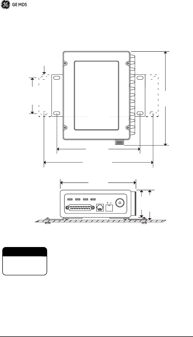
Figure 2 and Figure 3 show the interface connectors and indicators on
the transceiver’s front an d rear panels. These items are referenced in
the installation steps given later in this guide.

2 MDS SD4 Startup Guide 05-4819A01, Rev. 01
Invisible place holder
Figure 2. Antenna & DC Power Connectors
Invisible place holder
Figure 3. Data Interface Connector & LED Status Panel
INSTALLATION
There are three main requirements for installing the transceiver:
• Adequate and stable primary power
• An efficient and properly installed antenna system
• Correct data connections between the transceiver and the data
device.
Antenna
(Mini-UHF)
Power Input
(10.5 to 16 Vdc @ 8A)
LED Indicator Panel
(See inset above)
Data Interface
(DB-25)
PWR
DCD
TXD
RXD
05-4819A01, Rev. 01 MDS SD4 Startup Guide
3
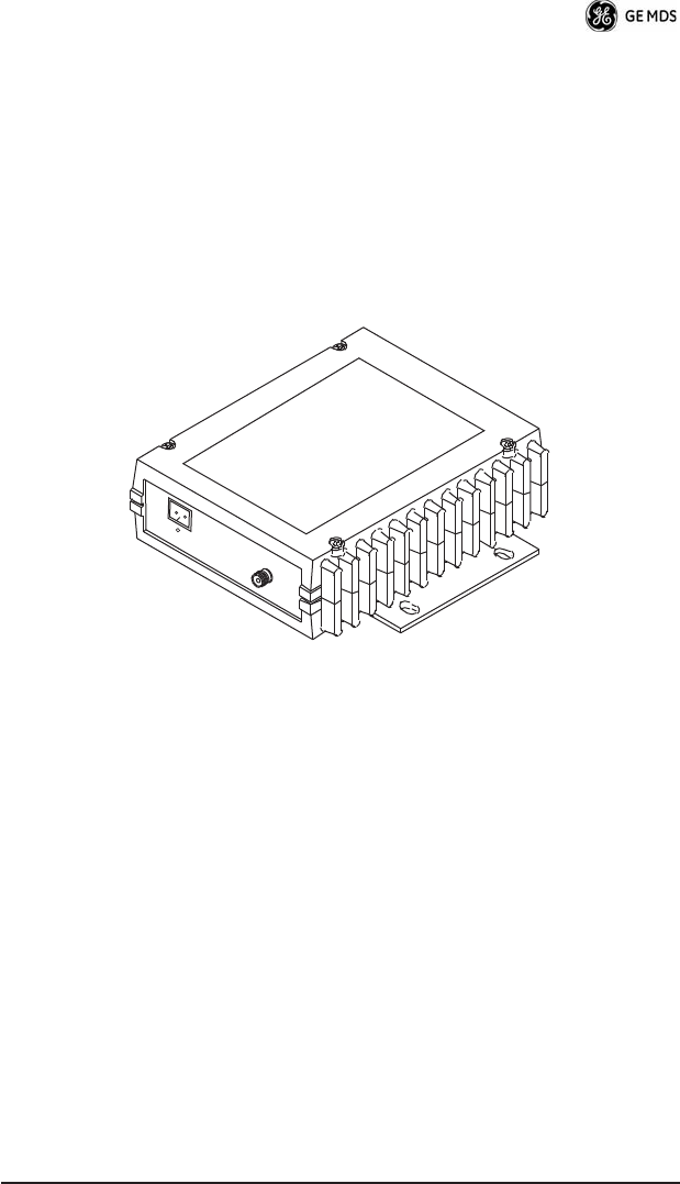
Figure 4 shows a typical station arrangement. This is followed by
step-by-step procedures for installing the transceiver and making front
and rear panel connections.
Figure 4. Typical Station Arrangement
Installation Steps
Below are the basic steps for installing the transceiver. Refer to
Figure 4 as necessary to make the cable connections.
1.
Mount the transceiver to a stable surface
using the brackets
supplied with the radio. Begin by attaching the radio’s mounting
brackets to the bottom of the transceiver case (if not already
attached) using the four 6-32 x 1/4 inch (6 mm) screws supplied.
Figure 5 shows the mounting bracket dimensions.
DC POWER CABLE
10.5—16 VDC @ 8A
Negative Ground
DATA EQUIPMENT
ANTENNA
SYSTEM
LOW-LOSS
COAXIAL CABLE
(50 Ohm)
RADIO
TRANSCEIVER
4 MDS SD4 Startup Guide 05-4819A01, Rev. 01
NOTE:
To prevent moisture from entering the radio, do not mount the
case with the cable connectors pointing up. Also, dress all
cables to prevent moisture from running along the cables and
into the radio.
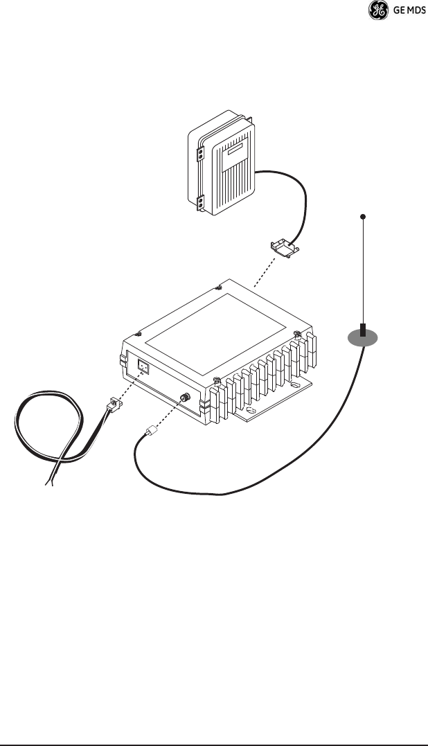
Invisible place holder
Figure 5. Transceiver Mounting Bracket Dimensions
Using screws longer than 1/4 inch (6 mm) to attach the
brackets to the radio may damage the internal PC
board. Use only the supplied screws.
2.
Install the antenna and feedline
for the station. The antenna
used with the transceiver must be designed to operate in the
radio’s frequency band, and be mounted in a location that pro-
vides a clear, path to the other associated station(s). Use low loss
coaxial feedline and keep the cable as short as possible.
8.5"
216 mm
1.75"
4.44 CM
6.63"
168 mm
2.75"
70 mm
7.25"
184 mm
ALTERNATE
POSITION
5.625"
143 mm
2.25"
57 mm
2.0"
50 mm
CAUTION
POSSIBLE
EQUIPMENT
DAMAGE

05-4819A01, Rev. 01 MDS SD4 Startup Guide
5
3.
Connect the data equipment
to the
DATA INTERFACE
connec-
tor. Check DATA INTERFACE REFERENCE on Page 13 for pin
wiring details.
Note: The radio’s DIAGNOSTICS port is used for reprogramming
the radio’s firmware.
4.
Connect primary power to the transceiver.
Power applied must
be within 10.5–16 Vdc and capable of continuously providing at
least 8 Amperes. A power connector with is provided with each
unit (see Figure 4).
The transceiver is designed for use with nega-
tive-ground systems only. The power supply should be
equipped with overload protection (NEC Class 2 rating),
to protect against a short circuit between its output ter-
minals and the radio’s power connector.
5.
Set the radio’s configuration.
The transceiver is designed for
quick installation with a minimum of software configuration
required.
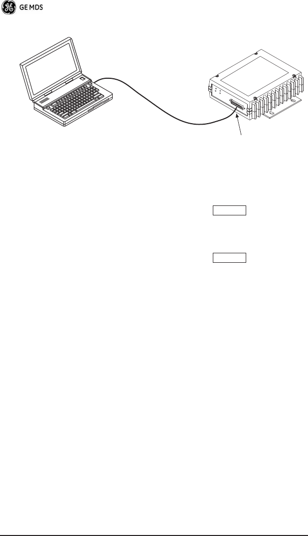
a. Connect a PC to the transceiver’s
DATA INTERFACE
connec-
tor as shown in Figure 6. If desired, a cable may be built using
the information shown on Page 13 of this guide.
b. Launch a terminal communications program, such as Hyper-
Terminal (included with most Windows
TM
systems). Press the
key a few times (at half-second intervals) to receive
the ready “>” prompt on the screen.
NOTE:
To prevent unintended keying of the transmitter during
management activities, set
PTTSIG
to
OFF
, or do not
connect to Pin 6 of the
COM1
port.
CAUTION
POSSIBLE
EQUIPMENT
DAMAGE
ENTER
6 MDS SD4 Startup Guide 05-4819A01, Rev. 01
Invisible place holder
Figure 6. PC Configuration Setup
c. Set the transmit frequency by entering
TX xxx.xxxx
, where
xxx.xxxx
is the frequency in MHz. Press
.
The
response
PROGRAMMED OK
indicates successful entry.
d. Set the receive frequency by entering
RX xxx.xxxx
, where
xxx.xxxx
is the frequency in MHz. Press
.
The
response
PROGRAMMED OK
indicates successful entry.
e. Set the radio’s modem type if necessary, using the
MODEM
xxxx
command, where
xxxx
is the modem selection (typically
4800
or
9600
). The default setting is
9600
. Set the radio’s serial
data interface rate (typically
BAUD 9600 8N1
).
This completes the initial setup and configuration of the radio.
PC Running Terminal Session
Transceiver
To DB-25
Data Interface Port
ENTER
ENTER

05-4819A01, Rev. 01 MDS SD4 Startup Guide
7
SOFTWARE COMMAND SUMMARY
Table 1 lists software commands commonly used during initial instal-
lation and setup of the transceiver.
Detailed Command Usage
(This section currently under revision)
chan [chan # [rxfreq # [txfreq # [pwr # [bw # ] ] ] ] }
Table 1. Command Summary
Command Name Function
BAUD [xxxx xxx]
Sets radio’s serial data interface rate/format.
Default setting is BAUD 9600 8N1.
DKEY
Dekey the radio (transmitter OFF). This is
generally a radio test command.
KEY
Key the radio (transmitter ON). This is
generally a radio test command.
MODEM [xxxx]
Set the modem characteristics of the radio.
PWR [37–45]
Set or display the transmit power setting.
PTTSIG [ON, OFF]
Set/display push-to-talk configuration.
RSSI
Display the Received Signal Strength
Indication.
RX [xxx.xxxx]
Set or display receiver frequency.
SER
Display the radio serial number.
SNR
Signal-to-Noise Ratio (in dB).
SPECTRUM
[xxx.xx]
Display internal spectrum analyzer, where
xxx.xx
characters denote center frequency
in MHz. The command
spectrum
may be
entered alone to view current operating
channel.
SREV
Display the Software Revision Level.
STAT
Display radio status and alarms.
TEMP
Display the internal temperature of the radio
in degrees C.
TX [xxx.xxxx]
Set or display the transmit frequency.

8 MDS SD4 Startup Guide 05-4819A01, Rev. 01
chan - channel # {all,0-8]
rxfreq - receiver frequency
txfreq - transmitter frequency
pwr - power in watts (5, 20, 25, 30)
bw - bandwidth (12.5, 25)
>chan
Channel 1 RX 452.92500 MHz TX 452.92500 MHz PWR 30 Watts BW
25.000 KHz
>chan all
Selected LCT Channel is 0
Channel 0 RX 450.00000 MHz TX 453.00000 MHz PWR 5 Watts BW 25.000
KHz
Channel 1 RX 452.92500 MHz TX 452.92500 MHz PWR 30 Watts BW
25.000 KHz
Channel 2 RX 452.95000 MHz TX 452.95000 MHz PWR 30 Watts BW
25.000 KHz
Channel 3 RX 457.92500 MHz TX 457.92500 MHz PWR 30 Watts BW
25.000 KHz
Channel 4 RX 457.95000 MHz TX 457.95000 MHz PWR 30 Watts BW
25.000 KHz
Channel 5 RX 452.92500 MHz TX 452.92500 MHz PWR 30 Watts BW
25.000 KHz
Channel 6 RX 452.95000 MHz TX 452.95000 MHz PWR 30 Watts BW
25.000 KHz
Channel 7 RX 457.92500 MHz TX 457.92500 MHz PWR 30 Watts BW
25.000 KHz
Channel 8 RX 457.95000 MHz TX 457.95000 MHz PWR 30 Watts BW
25.000 KHz
>chan 8 rxfreq 453
rxfreq 453
Channel 8 RX 453.00000 MHz TX 457.95000 MHz PWR 30 Watts BW
25.000 KHz
>chan 8 pwr 20
pwr 20
Channel 8 RX 453.00000 MHz TX 457.95000 MHz PWR 20 Watts BW
25.000 KHz
>chan 8 bw 12.5
bw 12.5

05-4819A01, Rev. 01 MDS SD4 Startup Guide
9
Channel 8 RX 453.00000 MHz TX 457.95000 MHz PWR 20 Watts BW
12.500 KHz
>mode test
>selchan help
Usage:
selchan [0-8]
>selchan 8
Channel Number 8
>chan
Channel 8 RX 453.00000 MHz TX 457.95000 MHz PWR 20 Watts BW
12.500 KHz
>key
TRANSMITTER ENABLED
>dkey
TRANSMITTER DISABLED
>mode normal
TROUBLESHOOTING
For proper operation, all radios in the network must meet these basic
requirements:
• Adequate and stable primary power
• Secure connections (RF, data and power)
• A clear transmission path between stations
• An efficient antenna system providing adequate received signal
strength.
• Proper programming of the transceiver’s operating parameters
• The correct interface between the transceiver and the connected
data equipment (correct cable wiring, proper data format, tim-
ing, etc.)
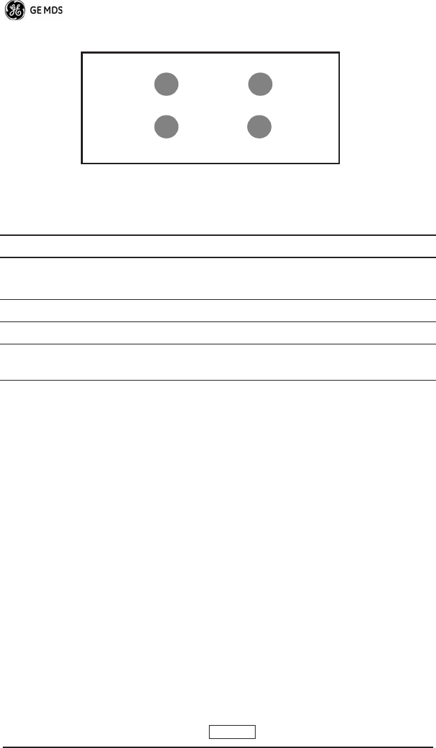
LED Indicators
The LED status indicators (Figure 7) are an important troubleshooting
aid and should be checked whenever a problem is suspected. Table 2
describes the function of each status LED on the front panel of the
radio.
10 MDS SD4 Startup Guide 05-4819A01, Rev. 01
Invisible place holder
Figure 7. LED Indicators
Event Codes
When an alarm condition exists, the transceiver creates a code that can
be read on a connected terminal. These codes can be helpful in
resolving many system difficulties. Refer to Table 3 (Page 11) for a
definition of the event codes.
Checking for Alarms
—STAT command
To check for alarms, connect a terminal to the radio’s
DIAGNOSTICS
port. See DATA INTERFACE REFERENCE on Page 13 for pinout
information.
Enter
STAT
on the connected terminal. If no alarms exist, the message
NO ALARMS PRESENT
appears on the display.
If an alarm does exist, a two-digit alarm code (00–31) is displayed and
the event is identified as a Major or Minor Alarm. A brief description
of the alarm is also given.
If more than one alarm exists, the word
MORE
appears on the screen.
To view additional alarms, press .
Table 2. LED Status Indicators
LED Name Description
PWR
• Continuous—Power applied, no problems detected.
• Rapid flash (5 times-per-second)—Alarm indication.
TXD
Data being transmitted over the air.
RXD
Data being received over the air.
DCD
When lit, indicates that a communication link is established
with the other station(s).
PWR
DCD
TXD
RXD
ENTER

05-4819A01, Rev. 01 MDS SD4 Startup Guide
11
Major Alarms vs. Minor Alarms
Major Alarms
—report serious conditions that generally indicate a
hardware failure, or other abnormal condition that will prevent (or
seriously hamper) further operation of the transceiver. Major alarms
generally indicate the need for factory repair. Contact your factory
representative for assistance.
Minor Alarms—
report conditions that, under most circumstances will
not prevent transceiver operation. This includes out-of-tolerance con-
ditions, baud rate mismatches, etc. The cause of these alarms should
be investigated and corrected to prevent system failure.
Event Code Definitions
Table 3 contains a listing of event codes that may be reported by the
transceiver. The codes shown are a subset of a larger pool of codes
used for various GE MDS products.
For this reason, the table does not
show a sequential listing of all code numbers.
Only the codes appli-
cable to this product are shown.
Table 3. Event Codes
Event
Code
Event
Class Description
01 Major Improper software detected for this radio model.
04 Major The RF synthesizer is reporting an out-of-lock
condition.
08 Major The system is reporting that it has not been
calibrated. Factory calibration is required for proper
radio operation.
12 Major Receiver time-out. No data received within the
specified receiver time-out time.
13 Minor A Transmitter timeout was detected. The radio
stayed keyed longer than the duration specified by
the TOT command.
17 Minor A data parity fault has been detected on the
PAYLOAD port. This usually indicates a parity
setting mismatch between the radio and the
customer equipment.
18 Minor A data framing error has been detected on the
PAYLOAD port. This may indicate a baud rate
mismatch between the radio and the customer
equipment.

12 MDS SD4 Startup Guide 05-4819A01, Rev. 01
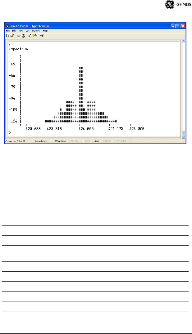
Internal Spectrum Analyzer
The radio contains a built-in spectrum analyzer tool (Figure 8) that can
be displayed on a connected PC. The tool is helpful in diagnosing
interference problems on or near your channel frequency.
Access the spectrum analyzer by entering
spectrum
at the command
prompt. A display appears showing detected signals on your current
channel.
Optionally, you can specify a frequency at the command prompt to
view the surrounding spectrum of that frequency. To do this, enter
spectrum xxx.xx, where xxx.xx is the frequency in MHz.
As shown in Figure 8, the display creates a received signal strength
indication (RSSI) vs. frequency plot for the frequency and sur-
rounding signals. By analyzing the display, you can determine the
presence of other signals near the transceiver’s operating frequency.
This information can be helpful in troubleshooting interference prob-
lems.
26 Minor The DC input voltage is out-of-tolerance. If the
voltage is too far out of tolerance, operation may fail.
31 Minor The transceiver’s internal temperature is
approaching an out-of-tolerance condition. If the
temperature drifts outside of the recommended
operating range, system operation may fail.
Table 3. Event Codes (Cont’d)
Event
Code
Event
Class Description
05-4819A01, Rev. 01 MDS SD4 Startup Guide 13
Invisible place holder
Figure 8. Internal Spectrum Analyzer Display
DATA INTERFACE REFERENCE
(This section currently under revision)
Table 4 lists the pin functions on the DB-25 DATA INTERFACE con-
nector.
Table 4. LED Status Indicators
Pin No. Description
1 No connection.
2Ground—Connects to ground (negative supply potential)
on the radio’s PC board.
3 No connection.
4Detected Audio.
5Channel 3 Select (see Note 1).
6RX(A) RS-485 digital.
7Data PTT (Keying Signal).
8RX(B) (RS-485 digital

14 MDS SD4 Startup Guide 05-4819A01, Rev. 01
Notes:
Note 1: Channel select decoding: (High = no connection, Low= Gnd)
Chan 3 Chan 2 Chan 1 Chan 0 Selected
High (future use) High High High 1
High (future use) High High Low 2
High (future use) High Low High 3
High (future use) High Low Low 4
High (future use) Low High High 5
High (future use) Low High Low 6
High (future use) Low Low High 7
High (future use) Low Low Low 8
9+5 Vdc to programming device
10 Programming data (bi-directional [SRI] or TD [ARIA])
11 Ground—Connects to ground (negative supply potential)
on the radio’s PC board.
12 Power Switch Contact (momentary ground changes
state) (Unique to SRI)
13 Return (Ground) to programming interface.
14 Channel 2 select (See Note 1)
15 Programming data, RD (unique to ARIA)
16 NCData Interface Control (High = analog input, Low=
digital input)
17 TX Audio
18 Ground—Connects to ground (negative supply potential)
on the radio’s PC board.
19 Channel 0 select (Note 1)
20 +13.6 VDC
21 Ground—Connects to ground (negative supply potential)
on the radio’s PC board.
22 +13.6 VDC
23 Channel 1 select (Note 1)
24 NCTBD – TX(A) (RS485 digital)
25 NCTBD – TX(B) (RS485 digital)
Table 4. LED Status Indicators

05-4819A01, Rev. 01 MDS SD4 Startup Guide 15
SPECIFICATIONS
GENERAL
Frequency Range*: 450–512 MHz
RECEIVER
Maximum Usable Sensitivity: –110 dBm at 1x10⁻⁶ BER (Preliminary)
Bandwidth: 12.5 kHz
TRANSMITTER
RF Carrier Power: 5 Watts to 30 Watts
Duty Cycle: 25%
Output Impedance: 50 Ω
Channel Spacing: 6.25, 12.5, 25 kHz
FCC Emission Designators:
12.5 kHz B/W: 9K25F1D, 9K25F2D, 9K25F3D
25.0 kHz B/W: 16K5F1D. 16K5F2D, 16K5F3D
DATA CHARACTERISTICS
Payload Signaling Type: EIA/RS-485
Connector Type: DB-25 Female
Payload Data Rates: 300–115200 bps, asynchronous
Payload Data Latency: 10 ms maximum
DIAGNOSTICS INTERFACE
Signaling Standard: RS-232
PRIMARY POWER
Voltage: 13.8 Vdc Nominal (10.5 to 16 Vdc)
Negative-Ground Systems Only
TX Supply Current: 8 Amperes (Typical) @ 30 Watts Output
RX Supply Current: Operational—125 mA, Nominal
Fuse: 8-Ampere, internal
ENVIRONMENTAL
Humidity: 95% at 40 degrees C (104°F),
non-condensing
Temperature Range: –40 to 70 degrees C (–40°F to +158°F)
Weight: 1.0 kilograms

16 MDS SD4 Startup Guide 05-4819A01, Rev. 01

Installation Guide

GE MDS, LLC
Rochester, NY 14620
General Business: +1 585 242-9600
FAX: +1 585 242-9620
Web: www.GEmds.com
175 Science Parkway