GE MDS DS-MERCMIMO3 Wireless Data Transceiver User Manual 05 6301A Mercury MIMO Setup Guide
GE MDS LLC Wireless Data Transceiver 05 6301A Mercury MIMO Setup Guide
GE MDS >
User's Manual
05-6301A01, Rev. 01 MDS Mercury Series Quick Start 1
MDS Mercury Series
Setup Guide
MDS MercuryTM Series transceivers provide an easy-to-install
wireless network service with long range and secure operation at
adaptive data rates approaching 30 Mbps. The transceiver is
designed for demanding applications in industrial environments,
where reliability and range are paramount.
The transceiver comes in two primary models—Base Station (BS)
and Subscriber Unit (SU), each with unique hardware profiles.
Both models support Ethernet and serial services.
A BS is a wireless switch that usually provides connectivity into a
wired Ethernet LAN/WAN. Subscriber Units associate over the air
with a BS and are typically connected to an Ethernet or Serial
device via a local cable.
NOTE: To determine whether a unit is an BS or Subscriber Unit,
check the dome label on the top of the unit.
Refer to the Mercury Series Technical Manual (05-6302A01) for
advanced procedures and cautionary information.
1.1 Connectors & Indicators
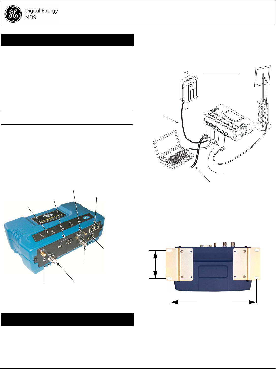
Figure 1 shows the connectors and indicators of a Standard BS.
These items are referenced in the installation and operation steps
that follow. Note that SU radios may have an additional connector
present for WiFi service, depending on order requirements. If WiFi
is not provided on an SU, the GPS connector will also be absent.
Invisible place holder
Figure 1. Connectors and Indicators
(Standard BS shown; SU Similar)
There are three main requirements for installing the transceiver—
adequate and stable primary power, a good antenna system, and
the correct interface between the transceiver and the data device.
Figure 2 shows a typical Mercury installation.
2.1 Installation Steps
Listed below are the basic steps for installation. It is highly recom-
mended that the BS be installed first so that you can quickly check
the operation of each associated SU as it is placed on the air.
Invisible place holder
Figure 2. Typical Mercury Installation (SU Shown; BS Similar)
2.1.1 Step 1—Mount the Transceiver
Use the supplied 6-32 x 1/4 inch (6 mm) screws to attach the
mounting brackets to the bottom of the radio. Figure 3 shows the
mounting dimensions of the unit. Mount the radio to a stable sur-
face. (Fasteners not supplied.)
Invisible place holder
Figure 3. Transceiver Mounting Dimensions
(Dimensions for BS and SU identical)
2.1.2 Step 2—Install the Antenna
Base units typically use sector antennas, while SU’s typically use
a directional panel antenna. All antennas should be mounted in the
clear to a sturdy support. Connect the antenna’s feedline cable to
the transceiver’s WiMAX Antenna Port. To minimize RF interfer-
ence, the antenna should be at least 9 inches (> 23 cm) away from
connected device(s), sensors and other external components.
1.0 INTRODUCTION
2.0 INSTALLATION
DC INPUT
(1060 VDC, 4A MAX)
RS-232
SERIAL PORT
LAN PORTS
USB PORTS
(Mini-A, Type-A)
GPS ANTENNA
CONNECTION
WiMAX RF
CHANNEL 1
WiMAX RF
CHANNEL 2
LED INDICATOR
PANEL
TO DC POWER SUPPLY
(1060 Vdc)
RTU/PLC
LOW-LOSS FEEDLINE
(To Station Antenna)
PC RUNNING
TERMINAL
PROGRAM
(Straight-Through
Cable to Radio)
TO GPS ANTENNA
(Provides 3.3 Vdc output)
Crossover Cable
to Radio
ANTENNA SYSTEM
Subscriber: Panel Ant.
Base Unit: Sector Ant.
2.75˝ (7 cm)
8 5/8˝ (21.8 cm)

2 MDS Mercury Series Quick Start 05-6301A01, Rev. 01
Install GPS Antenna (if required)
Install the GPS antenna in accordance with the manufacturer’s
instructions. Connect it to the GPS Port on the unit’s front panel.
2.1.3 Step 3—Measure & Connect DC Power
The DC input to the transceiver must be within 10–60 Vdc and
capable of continuously providing at least 150 watts. A power con-
nector with screw-terminals is provided with each unit. Strip the
wire leads to 6 mm (1/4 inch). Be sure to observe proper polarity
with the positive lead (+) on the left, and the negative on the right.
The unit is designed for use in negative ground systems only.
The power supply should be equipped with
overload protection (NEC Class 2), to protect
against a short circuit between its output ter-
minals and the radio’s power connector.
NOTE: It takes about 30 seconds for the unit to fully power up,
and a few minutes to associate with another unit, espe-
cially if GPS is required for time synchronization.
2.1.4 Step 4—Review the Transceiver’s
Configuration
One key setting must be known before beginning configuration:
•IP Address—Must be a unique address to allow for IP
access through the LAN port or over-the-air. Check with
your System Administrator for this information. (Default
address is 192.168.1.1)
Other parameters commonly needing review or adjustment are
listed below, followed by Log-in and Configuration procedures.
•RF Output Power Level (BS Only)—Check and adjust as
necessary for compliance with regulatory limits. (Default
power is +30 dBm for 1800 model, +23 dBm for 3650
model.) Note that Subscriber Units auto-adjust power output
based on target receive signal level (set at the BS).
•Password—Used for remote access and Menu System.
•Frequency—Operating frequency in MHz.
•TDD Sync Mode (BS only)—Selections are: Free Run and
GPS Required.
Free Run allows rapid configuration and initial testing.
GPS Required synchronizes the BS’s transmissions to the
GPS timing. GPS Required is only needed to synchronize
multiple Base Stations.
NOTE: The default password and username is admin.
A unique IP address and subnet are required to access the Menu
System, either through the LAN port, or remotely over-the-air.
Log-in and Configuration Procedure
The following is an overview of the local log-in and configuration
procedure using the COM1 serial port.
a. Connect a computer’s serial port to the unit’s COM1 Port.
b. Launch a terminal communication program, such as
HyperTerminal, on the computer. Configure it to: 115,200
bps/8N1/no handshaking/VT100.
c. Press ENTER. A login prompt is displayed that requires a
username and password.
d. Enter the username and password.
e. Review other settings and make changes as necessary,
such as the unit password, IP address, and security.
f. Under the Radio Configuration Menu at the Base Station,
set/verify the following:
Transmit Power—Settable from: -30 dBm to +30 dBm
(BS); 0 dBm to +30 dBm (SU); +23 dBm for 3650 models.
Receive Power—Target receive signal of the BS which
SUs will seek to adjust to, based on distance.
g. Under the Frequency Control Menu of the Radio Con-
figuration Menu, set/verify as required. Ensure that the
SU’s radio parameters are consistent with the BS's Fre-
quency Parameter.
Repeat above steps for each radio in the network. An overview
chart of the entire Menu System is shown in Figure 4 on Page 4.
NOTE: Using Configuration Scripts under the Mainte-
nance/Tools menu can aid in configuring multiple units.
2.1.5 Step 5—Connect the Data Equipment
Connect data equipment to the unit’s LAN port (10/100 BaseT), or
the serial port, depending on the type of equipment used.
Use a straight-through Ethernet cable to connect the LAN port to a
hub or switch; use a crossover cable to connect it directly to an
Ethernet device (PC, PLC, RTU).
2.1.6 Step 6—Check for Normal Operation
This step verifies the proper operation of wireless communications
between a BS and its associated SUs.
At All Units...
Observe the transceiver’s LED panel for the proper indications
(see Table 1). In a normally operating system, the radio will typi-
cally become associated in about two minutes from start-up.
At the Base Station...
a. If the BS is the first unit you are installing, send a PING
command to it through the LAN port. This verifies basic
LAN connectivity.
b. If you have already installed an SU, try sending a PING to
that unit through the Menu System PING utility or a
device connected to the unit on the same subnet.
At Subscriber Units...
a. Look for the LINK LED to turn on and stay on. This indi-
cates the unit has successfully associated with the net-
work’s Base Station. (The may take up to 30 seconds.)
b. View the Starting Information screen for the Device Sta-
tus and Connection Status). It will show one of these:
Initializing—This is the first phase after boot-up.
Scanning—The unit is looking for a Base Station beacon signal.
Ranging—Unit is adjusting power, timing, & frequency with a BS.
Authenticating—(When Device Authentication is used.) The SU
is authenticating to the network to obtain clearance.
Associated —The unit has successfully synchronized and associ-
ated with a Base Station. This is the normal state of the radio.
Alarmed—The unit has detected one or more uncleared alarms.
c. When the network is operating properly based on obser-
vation of the unit’s LEDs, connect a computer to the trans-
ceiver’s data port that will be used by the local terminal
equipment. Send the PING command to verify communi-
cations integrity with the Base Station.
d. After the PING is successful, connect the terminal equip-
ment to the radio’s data port and verify normal operation.
If above checks are OK, you are finished with the installation at this
site.
CAUTION
POSSIBLE
EQUIPMENT
DAMAGE

05-6301A01, Rev. 01 MDS Mercury Series Quick Start Guide 3
2.2 ANTENNA AIMING
Directional antennas usually require some fine-tuning of their
bearing to optimize the received signal strength. The SU has a
built-in received signal strength indicator (RSSI) that can be used
to optimize the received signal level. It is available under the Per-
formance Information menu.
In general, signal levels stronger than –80 dBm will provide reliable
communication in the network. RSSI measurements and Wireless
Packet Statistics are based on multiple samples over a period of
several seconds. The average of these measurements is dis-
played by the RSSI screen. Follow the steps below to aim the
antenna for best received signal level.
2.2.1 Procedure
1. Verify the SU is associated with a Base Station unit by
observing the LINK LED. It should be on or blinking.
2. a) View and record the Wireless Packets Dropped and
Received Error rates (Main Menu>Performance Informa-
tion>Packet Statistics). This information will be used later.
b) Read the RSSI level at the Subscriber Unit (Main
Menu>Performance Information>Internal Radio Status).
3. Optimize RSSI by slowly adjusting the direction of the
antenna. Watch the RSSI indication for several seconds after
making each adjustment so that the RSSI accurately reflects
any change in the link signal strength. The less negative the
number, the stronger the signal.
4. View the Wireless Packets Dropped and Received Error
rates at the point of maximum RSSI level (Main Menu>Per-
formance Information>Packet Statistics). They should be
the same or lower than previously noted.
If the RSSI peak results in an increase in the Packets
Dropped and Received Error numbers, the antenna may be
aimed at an undesired signal. Try a different antenna heading.
2.3 TROUBLESHOOTING
It is best to begin troubleshooting at the BS, as the rest of the
system depends on it for network synchronization and configura-
tion. If the BS has problems, the operation of the entire network will
be affected.
All radios in the network must meet these basic requirements:
• Adequate and stable primary power
• An efficient and properly aligned antenna system
• Secure connections (RF, data & power)
• Proper programming of the unit’s operating parameters,
especially Frequency Selection and IP Address
• The correct interface between the radio and the connected
data equipment (proper cable wiring, data format and timing)
A chart of LED functions is provided on Page 4 of these instruc-
tions. Refer to the Technical Manual for suggestions on resolving
common system difficulties using the radio’s LEDs and Menu
system as a guide.
If problems cannot be resolved using the guidance provided here,
review the GE MDS website’s technical support area for recent
software/firmware updates, general troubleshooting help, and ser-
vice information. Additional help is also available from our Tech-
nical Services Department.
2.3.1 Resetting to Factory Defaults
In trouble cases where several menu parameters have been
changed and there is no track of changes, it may help to return the
unit to a known, factory default state. Configuration can then be
attempted again. Use this function with care, as all user-custom-
ized settings will be cleared.
To reset to factory defaults, select Maintenance/Tools>Reset to
Factory Defaults.
2.4 APPROVAL INFORMATION
2.4.1 FCC Part 15 Notice
The transceiver series complies with Part 15 of the FCC Rules.
Operation is subject to the following two conditions: (1) this device
may not cause harmful interference, and (2) this device must
accept any interference received, including interference that may
cause undesired operation. Any unauthorized modification or
changes to this device without the express approval of GE MDS
may void the user’s authority to operate this device. Furthermore,
the Mercury Series is intended to be used only when installed in
accordance with the instructions outlined in this guide. Failure to
comply with these instructions may void the user’s authority to
operate this device.
Part 15 rules also require that the Effective Isotropic Radiated
Power (EIRP) from a Mercury Series 1800 MHz installation not
exceed 36 dBm. For the Mercury 3650, EIRP must not exceed
1-watt per MHz.
NOTE: This equipment has been tested and found to comply with
the limits for a Class A digital device, pursuant to part 15 of the
FCC Rules. These limits are designed to provide reasonable pro-
tection against harmful interference when the equipment is oper-
ated in a commercial environment. This equipment generates,
uses, and can radiate radio frequency energy and, if not installed
and used in accordance with the instruction manual, may cause
harmful interference to radio communications. Operation of this
equipment in a residential area is likely to cause harmful interfer-
ence in which case the user will be required to correct the interfer-
ence at his own expense.
2.4.2 RF Exposure Notices
1800 MHz Models
Professional installation required. The radio equipment
described in this guide emits radio frequency energy. Although the
power level is low, the concentrated energy from a directional
antenna may pose a health hazard. Do not allow people to come
closer than 23 cm (9 inches) to the antenna when the transmitter
is operating in indoor or outdoor environments. More information
on RF exposure is on the Internet at
www.fcc.gov/oet/info/documents/bulletins.
3650 MHz Models
Professional installation required. The transceiver described
here emits radio frequency energy. Although the power level is low,
the concentrated energy from a directional antenna may pose a
health hazard. Do not allow people to come closer than 25 cm (9.8
inches) to the antenna when the transmitter is operating. This cal-
culation is based on an 18 dBi panel antenna. Additional informa-
tion on RF exposure is available on the Internet at
www.fcc.gov/oet/info/documents/bulletins.
GE MDS, LLC
175 Science Parkway
Rochester, NY 14620
MDS Mercury Series Setup Guide General Business: +1 585 242-9600
05-6301A01, Rev. 01 FAX: +1 585 242-9620
November 2010 (Copyright 2010, GE MDS, LLC) Web: www.gemds.com
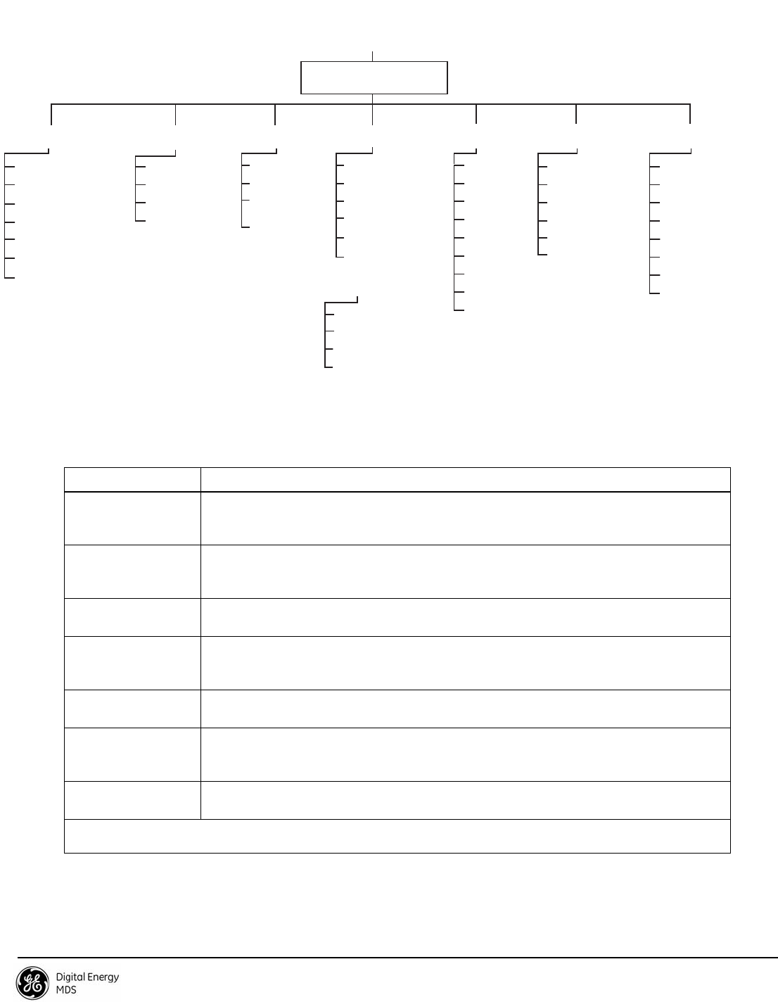
Invisible place holder
Figure 4. Menu Overview
Table 1: Description of LED Status Indicators
LED Name Description
PWR • ON—Power applied, no problems detected.
• FLASHING—Alarm present
• OFF—Primary power absent
LAN
(See Note below) • ON—LAN detected.
• FLASHING—Data TX/RX
• OFF—LAN not detected
COM1 • FLASHING—Data TX/RX activity
• OFF—No data activity
GPS • ON—Has GPS satellite fix
• FLASHING—Synchronizing timing reference
• OFF—No GPS satellite fix
LINK (BS) • ON—Operational state
• FLASHING—Data TX/RX
LINK (Subscriber) • ON—Associated to BS
• FLASHING—Data TX/RX
• OFF—Not Associated with BS
USB • ON—USB activity on either port
• OFF—No USB activity
NOTE: The unit’s LAN port also has two embedded LEDs to indicate signal activity as follows: A steady green indicates that a link
has been achieved; a flashing green indicates data activity; a yellow indicates 100 Mbps operation.
Ntwk. Intfc. Config
Ethernet Port Config
Bridge Configuration
SNMP Agent Config. (BS)
AP Location Info (SU)
Network
Configuration
Radio
Configuration
Device
Information Maintenance/Tools
Security
Configuration
Reprogramming
Config. Scripts
Ping Utility
Auth. Codes
Reset to Defaults
Radio Test
F/W Versions
F/W Upgrade
MAIN MENU
Transmit Power
Receive Pwr. (BS)
Freq. Control
Adv. Config.
Performance
Information
Serial Number
Uptime
Date
Date Format
Time
Model
Device Names
Console Bd. Rt.
UTC Time Offset
Device Security
Wireless Security
Event Log
Packet Statistics
GPS Status
Wireless Ntwk Stat.
WiMAX Radio Stat.
PerformanceT rend
Manage Certif.
RADIUS
Configuration
Starting Information Screen
(Read-Only Status)
Redundancy
Configuration (BS)
Redundancy Config.
Ntwk Event Triggers
Radio Event Triggers
Hdwr Event Triggers
Red. Config. Options
Force Switchover
SNTP Server Config.
802.11 Configuration
GPS
Configuration (SU)
Stream GPS to Console
Send GPS via UDP
GPS UDP Server IP Address
GPS UDP Server UDP Port
Spacebar is used to make some menu selections
BS = Base Station Only
SU = Subscriber Unit Only
NOTES
Chart shows top-level view only. See Reference Manual for details.
Not all menu items are-user configurable
Some parameters dependent on radio options