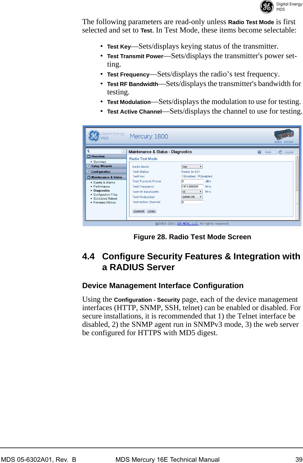
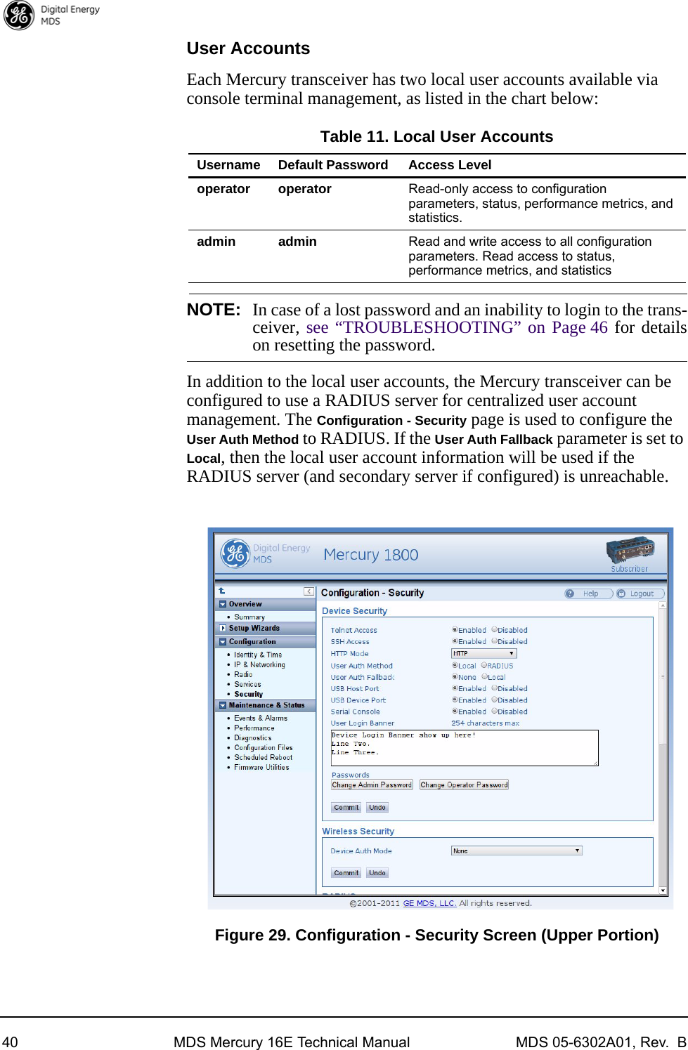
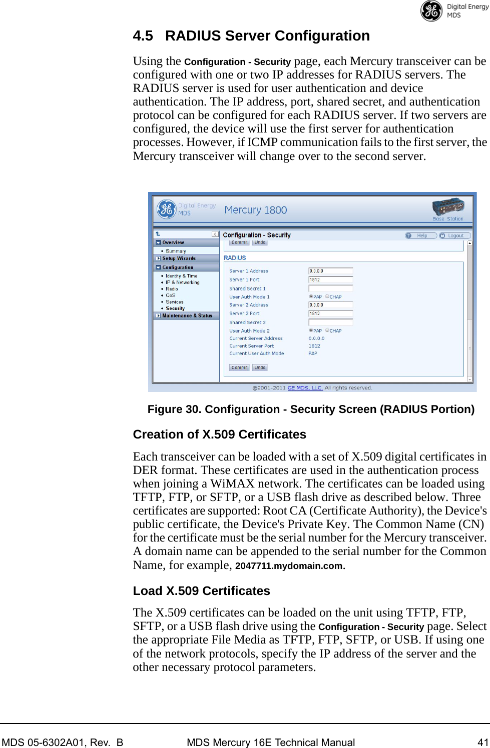
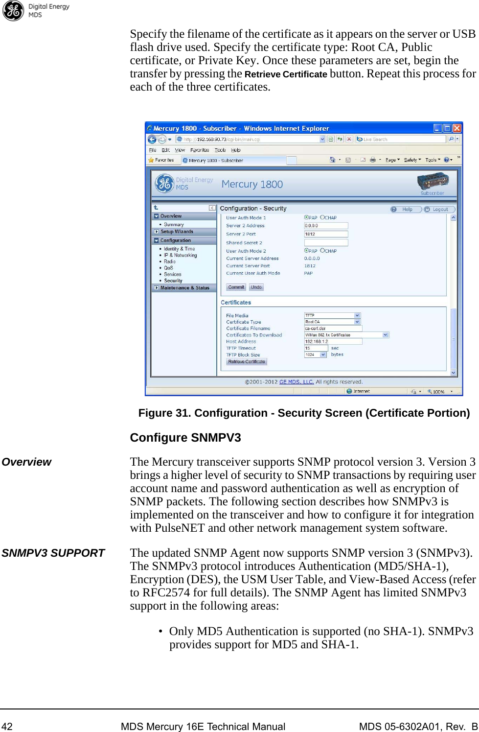
GE MDS DS-MERCMIMO5A WiMax Industrial Radio User Manual 05 6302A01B Mercury MIMO Front w 5800

GE MDS LLC WiMax Industrial Radio 05 6302A01B Mercury MIMO Front w 5800

User Manual

Installation and Operation GuideTechnical ManualMDS 05-6302A01, Rev. BFEBRUARY 2012Covering Subscriber, Base, and Outdoor Subscriber Unitsof the Mercury 16E SeriesMDS Mercury SeriesSecure, Long Range IP/Ethernet & Serial
Quick-Start instructions for this product are contained in publication 05-6301A01.All GE MDS user guides are available online at www.gemds.com
MDS 05-6302A01, Rev.  B MDS Mercury 16E Technical Manual iTABLE OF CONTENTS1.0   PRODUCT DESCRIPTION................................................................................................... 11.1   Product Models  .............................................................................................................................21.2   Key Features  .................................................................................................................................31.3   Key Specifications  .........................................................................................................................3Accessory Items...............................................................................................................................42.0   QUICK-START INSTRUCTIONS .......................................................................................... 52.1   Connecting to the Device Manager  ............................................................................................... 52.2   Configure IP Address and Identity ................................................................................................. 62.3   Basic Connectivity  .........................................................................................................................7Setup for Maximum Throughput ......................................................................................................93.0   FEATURE DESCRIPTIONS ................................................................................................. 93.1   Security Features  ..........................................................................................................................9Overview ..........................................................................................................................................9Authentication ................................................................................................................................10User Authentication........................................................................................................................10PKMv2 Device Authentication........................................................................................................10Test Auth Mode (for Bench Test/Evaluation).................................................................................. 11X.509 Certificates........................................................................................................................... 113.2   Multiple In / Multiple Out (MIMO) Operation ................................................................................ 113.3   ARQ and Hybrid ARQ  .................................................................................................................12ARQ Setup.....................................................................................................................................12HARQ Setup ..................................................................................................................................134.0   PERFORMING COMMON TASKS ..................................................................................... 144.1   Basic Device Management ..........................................................................................................14USB Console ................................................................................................................................. 14Using Configuration Scripts ...........................................................................................................15Perform Firmware Upgrade ...........................................................................................................16Instructions for Completing the Firmware Upgrade Process .........................................................17Configuring Networking Features for VLAN...................................................................................17Configure Serial Data Interface for TCP, UDP, MODBUS..............................................................21Configure QOS .............................................................................................................................. 25Flow Parameters............................................................................................................................26Quality of Service (QoS) Screen.................................................................................................... 27Creating a Service Flow................................................................................................................. 28QOS Example: Low Latency..........................................................................................................28QOS Example: Controlling Bandwidth in Video Applications......................................................... 28QOS Example: Prioritizing a Data Flow .........................................................................................29QoS Traffic Shaping.......................................................................................................................31
ii MDS Mercury 16E Technical Manual MDS 05-6302A01, Rev.  B4.2   802.11 Wi-Fi Interface (Optional Feature)  ...................................................................................31802.11 Configuration Options ........................................................................................................32802.11 Status .................................................................................................................................364.3   Radio Test Mode Menu  ...............................................................................................................384.4   Configure Security Features & Integration with a RADIUS Server ..............................................39Device Management Interface Configuration.................................................................................39User Accounts................................................................................................................................404.5   RADIUS Server Configuration  ..................................................................................................... 41Creation of X.509 Certificates ........................................................................................................41Load X.509 Certificates..................................................................................................................41Configure SNMPV3........................................................................................................................ 424.6   Use of the Antenna Alignment Tool  .............................................................................................455.0   TROUBLESHOOTING........................................................................................................ 465.1   LED INDICATORS .......................................................................................................................465.2   WiMAX Statistics  .........................................................................................................................465.3   Common Troubleshooting Scenarios  ..........................................................................................476.0   SITE INSTALLATION GUIDE ............................................................................................. 486.1   General Requirements  ................................................................................................................ 48Mounting Considerations ............................................................................................................... 496.2   Site Selection  ..............................................................................................................................506.3   Equipment Grounding  .................................................................................................................506.4   LAN Port  ...................................................................................................................................... 516.5   COM1 Port  .................................................................................................................................. 516.6   Antenna & Feedline Selection  .....................................................................................................52Antennas........................................................................................................................................52Feedlines ....................................................................................................................................... 53GPS Cabling & Antenna ................................................................................................................546.7   Conducting a Site Survey ............................................................................................................546.8   A Word About Radio Interference ................................................................................................ 546.9   Radio (RF) Measurements  ..........................................................................................................55Transmitter Power Output and Antenna System SWR ..................................................................55Antenna Heading Optimization ......................................................................................................567.0   PERFORMANCE NOTES................................................................................................... 577.1   Wireless Bridge  ...........................................................................................................................577.2   Distance-Throughput Relationship  ..............................................................................................587.3   Data Latency—TCP versus UDP Mode  ......................................................................................587.4   Packets-per-Second (PPS)  .........................................................................................................587.5   Subscriber-to-Subscriber Traffic ..................................................................................................587.6   Interference has a Direct Correlation to Throughput  ...................................................................597.7   Placing the Radio Behind a Firewall ............................................................................................ 598.0   INDEX OF CONFIGURATION PARAMETERS................................................................... 60
MDS 05-6302A01, Rev.  B MDS Mercury 16E Technical Manual iii9.0   dBm-WATTS-VOLTS CONVERSION CHART .................................................................... 76Band History .................................................................................................................................. 77Technical Details ............................................................................................................................77Exclusion Zones.............................................................................................................................77APPENDIX A—3650 MHz Band Information .............................................................................. 77APPENDIX B—Glossary of Terms & Abbreviations.................................................................... 79Copyright and TrademarkThis manual and all software described herein is protected by Copyright: 2012 GE MDS, LLC. All rights reserved. GE MDS, LLC reserves its right to correct any errors and omissions in this publication. Modbus® is a registered trademark of Schneider Electric Corporation. All other trademarks and product names are the property of their respective owners.FCC Part 15 NoticeThe transceiver series complies with Part 15 of the FCC Rules for a Class A digital device. Operation is subject to the following two conditions: (1) this device may not cause harmful interference, and (2) this device must accept any interference received, including interference that may cause undesired operation. Any unauthorized modification or changes to this device without the express approval of GE MDS may void the user’s authority to operate this device. Furthermore, the Mercury Series is intended to be used only when installed in accordance with the instructions outlined in this guide. Failure to comply with these instructions may void the user’s authority to operate the device.Industry Canada Notices (English and French)Industry Canada rules (SRSP 301.7) require that the power to the antenna on an 1800-1830 MHz installation shall not exceed 2 watts in any 1 MHz channel bandwidth.Industrie Canada (PNRH 301.7) exigent que le pouvoir de l'antenne sur une installation de 1800 à 1830 MHz ne doit pas dépasser 2 watts en tout bande passante de 1 MHz canal.For ODU installations: Under Industry Canada regulations, this radio transmitter may only operate using an antenna of a type and maximum (or lesser) gain approved for the transmitter by Industry Canada. To reduce potential radio interference to other users, the antenna type and its gain should be so chosen that the equivalent isotropically radiated power (e.i.r.p.) is not more than that necessary for successful communication.This device complies with Industry Canada licence-exempt RSS standard(s). Operation is subject to the following two conditions: (1) this device may not cause interference, and (2) this device must accept any interference, including interference that may cause undesired operation of the device.
iv MDS Mercury 16E Technical Manual MDS 05-6302A01, Rev.  BPour les installations ODU: Dans l'industrie des règlements du Canada, cet émetteur radio peut fonctionner uniquement à l'aide d'une antenne d'un type et un maximum (ou moins) de gain approuvé pour l'émetteur par Industrie Canada. Pour réduire le risque d'interférence aux autres utilisateurs, le type d'antenne et son gain doivent être choisis afin que la puissance isotrope rayonnée équivalente (PIRE) ne dépasse pas ce qui est nécessaire pour une communication réussie.Cet appareil est conforme la norme d'Industrie Canada exempts de licence RSS (s). Son fonctionnement est soumis aux deux conditions suivantes: (1) cet appareil ne peut pas causer d'interférences, et (2) cet appareil doit accepter toute interférence, y compris les interférences qui peuvent causer un mauvais fonctionnement de l'appareil.For IDU Installations: This radio transmitter (identify the device by certification number) has been approved by Industry Canada to operate with the antenna types listed below with the maximum permissible gain and required antenna impedance for each antenna type indicated. Antenna types not included in this list, having a gain greater than the maximum gain indicated for that type, are strictly prohibited for use with this device.Pour les installations UDI: Cet émetteur radio (identifier le périphérique par numéro de certification) a été approuvé par Industrie Canada pour fonctionner avec les types d'antennes énumérées ci-dessous avec le gain maximal admissible et l'impédance d'antenne requise pour chaque type d'antenne indiqué. Types d'antennes ne figurent pas dans cette liste, ayant un gain supérieur au gain maximum indiqué pour ce type, sont strictement interdites pour une utilisation avec cet appareil.RF Exposure Notices (English and French)1800 MHz Models Professional installation required. The radio equipment described in this guide emits radio frequency energy. Although the power level is low, the concentrated energy from a directional antenna may pose a health hazard. Do not allow people to come closer than 0.4 meters (15 inches) to the antenna when the transmitter is operating in indoor or outdoor environments. More information on RF exposure is available on the Internet at www.fcc.gov/oet/info/documents/bulletins.L'énergie concentrée en provenance d'une antenne directionnelle peut présenter un danger pour la santé. Ne pas permettre aux gens de s'approcher à moins de 0.4 metres à l'avant de l'antenne lorsque l'émetteur est en opération. On doit augmenter la distance proportionnellement si on utilise des antennes ayant un gain plus élevé. Ce guide est destiné à être utilisé par un installateur professionnel. Plus d'informations sur l'exposition aux rayons RF peut être consulté en ligne à l'adresse suivante: www.fcc.gov/oet/info/documents/bulletins3650 MHz ModelsProfessional installation required. The transceiver described here emits radio frequency energy. Although the power level is low, the concentrated energy from a directional antenna may pose a health hazard. Do not allow people to come closer than 25 cm (9.8 inches) to the antenna when the transmitter is operating. This calculation is based on an 18 dBi panel antenna. Additional information on RF exposure is available on the Internet at www.fcc.gov/oet/info/documents/bulletins.
MDS 05-6302A01, Rev.  B MDS Mercury 16E Technical Manual vL'énergie concentrée en provenance d'une antenne directionnelle peut présenter un danger pour la santé. Ne pas permettre aux gens de s'approcher à moins de 25 cm à l'avant de l'antenne lorsque l'émetteur est en opération. On doit augmenter la distance proportionnellement si on utilise des antennes ayant un gain plus élevé. Ce guide est destiné à être utilisé par un installateur professionnel. Plus d'informations sur l'exposition aux rayons RF peut être consulté en ligne à l'adresse suivante: www.fcc.gov/oet/info/documents/bulletins.5800 MHz ModelsProfessional installation required. The radio equipment described in this guide emits radio frequency energy. Although the power level is low, the concentrated energy from a directional antenna may pose a health hazard. Do not allow people to come closer than 0.2 meters (8 inches) to the antenna when the transmitter is operating in indoor or outdoor environments. More information on RF exposure is available on the Internet at www.fcc.gov/oet/info/documents/bulletins.L'énergie concentrée en provenance d'une antenne directionnelle peut présenter un danger pour lasanté. Ne pas permettre aux gens de s'approcher à moins de 0.2 metres à l'avant de l'antenne lorsque l'émetteur est en opération. On doit augmenter la distance proportionnellement si on utilise des antennes ayant un gain plus élevé. Ce guide est destiné à être utilisé par un installateur professionnel. Plus d'informations sur l'exposition aux rayons RF peut être consulté en ligne à l'adresse suivante: www.fcc.gov/oet/info/documents/bulletinsFCC Co-location Requirements: To meet FCC co-location requirements for transmitting antennas, a 20 cm (7.87 inch) separation distance is required between the unit’s Wi-Fi and funda-mental antennas.Servicing PrecautionsWhen servicing energized equipment, be sure to wear appropriate Personal Protective Equipment (PPE). During internal service, situations could arise where objects accidentally contact or short circuit components and the appropriate PPE would alleviate or decrease the severity of potential injury. When servicing radios, all workplace regulations and other applicable standards for live electrical work should be followed to ensure personal safety. Ethernet and Serial CablesThe use of shielded Ethernet and serial cables are required to ensure EMC compliance when operating this equipment.Manual Revision and AccuracyThis manual was prepared to cover a specific version of firmware code. Accordingly, some screens and features may differ from the actual unit you are working with. While every reasonable effort has been made to ensure the accuracy of this publication, product improvements may also result in minor differences between the manual and the product shipped to you. If you have additional questions or need an exact specification for a product, please contact GE MDS using the information at the back of this guide. In addition, manual updates can often be found on our web site at www.gemds.com.
vi MDS Mercury 16E Technical Manual MDS 05-6302A01, Rev.  B
MDS 05-6302A01, Rev.  B MDS Mercury 16E Technical Manual 11.0 PRODUCT DESCRIPTIONThe GE MDS Mercury SeriesTM transceiver is an easy-to-install WiMAX solution offering extended range, secure operation, and multi-megabit performance in a compact and rugged package. Mercury is ideally suited for wireless data applications in Smart Grid Electric, Oil and Gas, Water/Wastewater, and other industrial uses in fixed locations where range, reliability, throughput, and security are paramount.Figure 1. Mercury MIMO Series Transceiver(Top: Base Station, Bottom: Subscriber Unit)The transceivers are commonly used to convey SCADA traffic, automated metering, distribution automation, command and control traffic, text documents, graphics, e-mail, video, Voice over IP (VoIP), and a variety of other application data between field devices and WAN/LAN-based entities.Based on multi-carrier Orthogonal Frequency Division Multiplexing (OFDM), the transceiver features high speed/low latency, Quality of Service (QoS), Ethernet and serial encapsulation, and MIMO (multiple-input and multiple output)-enhanced performance. It also provides enhanced security including 128-bit AES encryption and EAP-TLS IEEE 802.1x Device Authentication. These features make the Mercury system the best combination of security, range, and speed of any industrial wireless solution on the market today.
2 MDS Mercury 16E Technical Manual MDS 05-6302A01, Rev.  BFor installation and setup instructions for these products, please refer to GE MDS publication 05-6301A01.1.1 Product ModelsThe Mercury transceiver is available in several different product models:• The indoor Base Station (BS) acts as the center of each point-to-multipoint network. It has two RJ-45 Ethernet ports and a DB-9 RS-232 serial port for data connections.• The indoor Subscriber Unit (SU) acts as one of the multipoints in the network. It also has two RJ-45 Ethernet ports and a DB-9 RS-232 serial port for data connections.• The Outdoor Subscriber Unit (ODU) is a weatherproof ver-sion of the standard Subscriber Unit. The ODU has one RJ-45 Ethernet port and a DB-9 serial port for data connections.Invisible place holderFigure 2. Outdoor Subscriber Unit (ODU)(Back of unit, showing interface connectors)The key features and options for the various models are listed in Table 1 below.Table 1. Mercury Models and InterfacesInterfaces Base Station Indoor Subscriber Outdoor SubscriberEthernet ports2 RJ-45 Ethernet with built-in Layer 2 switch2 RJ-45 Ethernet with built-in Layer 2 switch1 RJ-45 Ethernet. May be ordered as Power over Ethernet or AC modelSerial port1 DB-9 RS-232 1 DB-9 RS-232 1 DB-9 RS-232USB 1 USB host port1 USB device port1 USB host port1 USB device port1 USB host portWiMAX Dual TNC for MIMO (1800 and 3650 models)Dual SMA for MIMO (5800 model)Dual TNC for MIMO(1800 and 3650 models)Dual SMA for MIMO (5800 model)Internal RF connectionsGPS Internal receiver with SMA connectorOptional internal receiver with SMA connectorNone
MDS 05-6302A01, Rev.  B MDS Mercury 16E Technical Manual 31.2 Key FeaturesThe Mercury transceiver supports:• WiMAX IEEE 802.16e-2005 interoperability• Scalable OFDM using 512 or 1024 subcarriers• 2x2 MIMO on all models supporting Matrix A and Matrix B Space Time Coding, Spatial Multiplexing, Maximum Ratio Combining, and Maximum Likelihood Detection• PKMv2 security including AES-CCMP 128-bit encryption, EAP-TLS, and X.509 digital certificates• Hybrid ARQ up to Category 4• Adaptive modulation from QPSK with 1/2-rate FEC coding to 64-QAM with 5/6-rate coding• Quality of Service (QoS) including:• Unsolicited Grant Service (UGS), Real-time polling service (RTPS), Non-real-time polling service (nRTPS), Enhanced real-time polling service (eRTPS), Best Effort (BE)• Wi-Fi service available as an option for ODU and Subscriber units • SNMP MIB support: MIB-II, GE MDS Proprietary, WiMAX* * Expected availablity 20121.3 Key SpecificationsTable 2 lists key operational specifications for the Mercury Transceiver.Antenna External External 15 dBi panel ant. for 1800 model18 dBi panel ant. for 3650 model18 dBi panel ant for 5800 modelWi-Fi -- Optional reverse SMA connectorOptional reverse SMA connectorTable 1. Mercury Models and Interfaces (Continued)Table 2. Key SpecificationsPrimary Wireless IEEE 802.16E-2005 WiMAXLocal Interfaces(indoor models)Two channel WiMAX, TNC connectors (1800, 3650 models)Two channel WiMAX, SMA connectors (5800 model)Dual 10/100 Ethernet, RJ-45, auto-sense, auto-mdixDB9 Serial PortUSB host and device portsGPS receiver, SMA connector (Optional on Subscriber)Wi-Fi, Reverse SMA connectorLocal Interfaces(ODU models)(1) 10/100 Ethernet, RJ-45, auto-sense, auto-mdixDB-9 Serial PortUSB Host Port
4 MDS Mercury 16E Technical Manual MDS 05-6302A01, Rev.  BAccessory ItemsGE MDS can provide accessory items for use with the Transceiver, including the items listed below:• Antennas—Omni and directional types• USB cable, CAT5, serial DB9s• RF coaxial cable, connectorsFrequency Bands 1800 to 1830 MHz (Industry Canada)3650 to 3675 MHz (FCC, Industry Canada)5725 to 5825 MHz (FCC)Frequency step size 250 kHzBandwidth 3.5, 5, 7, 8.75, and 10 MHzWi-Fi (optional) 2.4 GHz, 802.11b/g protocolRF Power Output 1800 and 3650 models: 30 dBm for all units, except 23 dBm for 3650 ODU5800 model: +18.0 dBm for ODU; 17.7 dBm for indoor units (limited for FCC compliance)Transmitter Dynamic Range60 dB, 1 dB step sizeAntenna 1800 Subscriber: 15 dBi panel, dual-polarized1800 Base Station: 12 dBi sector, dual-polarized, 120o beamwidth3650 Subscriber: 18 dBi panel, dual-polarized3650 Base Station: 14 dBi sector, dual-polarized, 120o beamwidth5800 Subscriber: 18 dBi panel, dual-polarized5800 Base Station: 15.5 dBi sector, dual-polarized, 90o beamwidthInput Power  Indoor units: 10 to 60 VDCOutdoor units: Power over Ethernet10 to 60 Vdc110/220 VacPower Consumption (average ratings)1800 Base: 17 Watts1800 Subscriber: 10 Watts1800 ODU: 10 Watts3650 Base: 13 Watts3650 Subscriber: 8 Watts3650 ODU: 8 Watts5800 Base: 14 Watts5800 Subscriber: 9 Watts5800 ODU: 9 WattsOperating Temperature-30 to +70 degrees CUnit Dimensions(excluding connectors)Indoor Base/Subscriber: 4.5 x 7.75 x 2.75 inches (11.43 x 19.69 x 6.99 cm)ODU: 14.5 x 14.5 x 4.5 inches (37 x 37 x 11.5 cm)Table 2. Key Specifications (Continued)
MDS 05-6302A01, Rev.  B MDS Mercury 16E Technical Manual 52.0 QUICK-START INSTRUCTIONS2.1 Connecting to the Device ManagerThe Mercury transceiver contains a built-in web server, known as the Device Manager, for configuration and diagnostics. Each transceiver needs to have some basic configuration parameters set before placing the unit in service. To start the Device Manager, connect an Ethernet cable from the Mercury to the PC used for configuration. The radio’s Ethernet interfaces have auto-sense detection allowing a straight-through or crossover cable to be used. NOTE: The PC used for radio management must be in the radio’sdefault IP Subnet for communications to take place. It can bechanged once the desired IP address is chosen.To manage the radio, start a web browser and enter the unit’s IP address. The transceiver defaults to an IP address 192.168.1.1 and netmask 255.255.255.0. The Mercury will prompt for a username and password. The default entries for both of these fields are admin. NOTE: In case of a lost password and an inability to login, see“Common Troubleshooting Scenarios” on Page 47 for detailson resetting the password and the unit's configuration.Once connected to the Device Manager, the summary page shown in Figure 3 is displayed.Invisible place holderFigure 3. Mercury Summary Page Example(Shows connection after IP address has been changed)
6 MDS Mercury 16E Technical Manual MDS 05-6302A01, Rev.  B2.2 Configure IP Address and IdentityThe IP Address of the unit is configured on the Configuration - IP & Networking page. The IP address and netmask should be set according to the network configuration defined by the system administrator. Note that if the IP address is changed, the web browser session will need to be re-started with the new configuration.Invisible place holderFigure 4. Mercury Configuration-IP & NetworkingIn addition to the IP address, the unit can be configured with an optional Device Name for ease of administration. The name can be set on the Configuration - Identity & Time page.Invisible place holderFigure 5. Mercury Configuration —Identity & Time
MDS 05-6302A01, Rev.  B MDS Mercury 16E Technical Manual 72.3 Basic ConnectivityTo establish basic connectivity between a Base Station and a Subscriber, start the configuration with the Base Station. The IP address and Device Name will be as set from the factory (or by the previous user). With a factory-fresh unit, the Device Name will blank. The Configuration - Radio page contains the key parameters for configuring the WiMAX interface.Invisible place holderFigure 6. Mercury Configuration—RadioFor 3650 units, the frequency defaults to 3662.5 MHz and the bandwidth is set to 3.5 MHz. These default values are sufficient to perform benchtop testing prior to final installation. Set the frequency and bandwidth to the same values on the Base Station and Subscriber. If performing the test on a table, cable the units as shown in Figure 7. The attenuator cables should be connected to the radio’s TX/RX connectors.NOTE: The frequency default for the 1800 model is 1815 MHz. Forthe 5800 model it is 5800 MHz. Not all frequencies can beconfigured for each bandwidth. Ranges differ.
8 MDS Mercury 16E Technical Manual MDS 05-6302A01, Rev.  BInvisible place holderFigure 7. Benchtop Test SetupUse the Maintenance & Status - Performance page on the Subscriber to monitor the establishment of the link.Invisible place holderFigure 8. Maintenance and Status ScreenThe WiMAX Network Status will display a Connection Status of OPERATIONAL when the Subscriber is successfully linked to the Base Station. This pane also displays the signal strength and quality. For a cabled, benchtop test, an RSSI of -70 dBm is acceptable. For a -70 dBm signal, a signal-to-noise ratio (SNR) of 28 dB or greater is expected.
MDS 05-6302A01, Rev.  B MDS Mercury 16E Technical Manual 9Setup for Maximum ThroughputTo demonstrate maximum throughput, several configuration changes must be made. In addition, the link needs to be cabled according to Figure 7, with a strong signal, that is, above -70 dBm. If necessary, the link attenuation should be adjusted to reach the desired RSSI level. The transmit power of the Base Station should be reduced to 10 dBm to ensure that the Subscriber only receives the signal through the cables and not directly from enclosure to enclosure.With this strong signal the modulation rate downlink and uplink should be 64QAM FEC 5/6. There may need to be data flow, such as an ICMP ping, in order to have the modems shift up to this modulation rate. Both the Base Station and Subscriber need to be set for MIMO Type Matrix A/B. The Base Station should have HARQ (4) enabled and ARQ disabled. These changes are made using the Configuration - Radio page. This setup and configuration can be used with any RF bandwidth. Approximate aggregate throughput for each bandwidth is given below.* 28 Mbps aggregate throughput was attained at 64QAM FEC 5/6, 10 Mhz bandwidth and rev. 2.0.4 product firmware.3.0 FEATURE DESCRIPTIONS3.1 Security FeaturesOverviewThe Mercury transceiver employs many security features to keep the device, network, and data secure. Some of these features include WiMAX PKMv2, EAP-TLS, and AES-CCMP encryption on the WiMAX interface and HTTPS, SNMPv3, and RADIUS authentication for the configuration interfaces.Table 3. Throughput Ratings (Nominal)Bandwidth Aggregate Throughput3.5 MHz 7 Mbps5 MHz 10 Mbps7 MHz 15 Mbps8.75 MHz 16 Mbps10 MHz 28 Mbps*
10 MDS Mercury 16E Technical Manual MDS 05-6302A01, Rev.  BAuthenticationAuthentication is the process by which one network entity verifies that another entity is who or what it claims to be and has the right to join the network and use its services. Authentication in wireless SCADA networks has two primary forms: User Authentication and Device Authentication. User authentication allows a device to ensure that a user may access the device's configuration and services. Device authentication allows a network server to verify that a hardware device may access the network.User AuthenticationThe Mercury transceiver requires user login with an account and password in order to access the Device Manager menu. This process can be managed locally in which the device stores the user account information in its on-board non-volatile memory, or remotely in which a RADIUS server is used. The transceiver has two local accounts: operator and admin. The operator account has read-only access to configuration parameters and performance data. The admin account has read-write access to all parameters and data. NOTE: The Operator account has access through the web, console,Telnet, or SSH interfaces, but settings may only be viewed, notchanged.To centralize the management of user accounts, a RADIUS server may be used. Each Mercury transceiver must be configured with the IP address, port, shared secret, and authentication protocol of a RADIUS server. When a user attempts to login, the credentials are forwarded to the RADIUS server for validation.PKMv2 Device AuthenticationThe IEEE 802.16e-2005 WiMAX standard uses PKMv2 for securing the wireless channel. PKMv2 stands for Privacy Key Management version 2. The Privacy Key Management protocol is used to exchange keying material from the Base Station to the Subscriber. This keying material is used to encrypt data so that it is secure during transport over the air. The encryption keys are routinely rotated to ensure security.Initial keying material is obtained during the device authentication process. This occurs when a Subscriber attempts to join a Base Station. The Base Station initiates an EAP-TLS negotiation with the Subscriber to begin the device authentication process. The Subscriber is only allowed to transmit EAP messages until the authentication has finished successfully. The Base Station forwards messages to the RADIUS server where the decision to allow the Subscriber to join is made. If the Subscriber authenticates successfully and the RADIUS server allows
MDS 05-6302A01, Rev.  B MDS Mercury 16E Technical Manual 11the Subscriber to join the network, then the data encryption keying material is sent to the Base Station. The Base Station then continues the PKM protocol to further derive keying material that is used to secure transmissions between the Base Station and the Subscriber.The Subscriber must be configured with X.509 certificates that are appropriate for the Public Key Infrastructure (PKI) in which they are deployed. These certificates are used to identify and authenticate the Subscriber to the RADIUS sever.Test Auth Mode (for Bench Test/Evaluation)The Device Auth Mode can be set to Test Auth to enable encryption on the WiMAX link without requiring an AAA server. To use this mode, both the Base Station and the Subscriber(s) must be set to Test Auth. In this arrangement, the Base Station acts as a simple AAA server and authenticates the subscriber without actually evaluating its identity certificate. This is convenient when doing bench testing in which the performance with encryption enabled is to be measured but without the complexity of setting up a AAA server and identity certificates.X.509 CertificatesA digital certificate, also known as an X.509 certificate, is a file that contains identification data and asymmetric key material. Each certificate contains a Common Name that identifies the user or device that owns the certificate. The primary information in the certificate is the public key for the user or device and a digital signature proving the authenticity of the certificate's contents.The Mercury transceiver uses X.509 certificates in the EAP-TLS handshake during device authentication as described in the PKMv2 section above.NOTE: Certificates must start with the serial number of the radio towork.3.2 Multiple In / Multiple Out (MIMO) OperationMIMO stands for Multiple In / Multiple Out. The Mercury transceiver features 2x2 MIMO on all models. This means that there are two full transmit and receive channels on each device. The use of 2x2 MIMO causes the Mercury transceiver to have higher throughput and greater range and coverage than single channel devices in the same environment.
12 MDS Mercury 16E Technical Manual MDS 05-6302A01, Rev.  BThere are two operating modes that the Mercury supports. The first mode is Matrix A in which the Mercury uses Space-Time Coding (STC) on the transmitter to allow it to send the same data on each channel but coded differently in order to get transmit diversity. On the receive side, the Mercury transceiver uses Maximum Ratio Combining (MRC) to more accurately reconstruct the received signal by using both receive channels. The second mode is Matrix B in which the Mercury uses Spatial Multiplexing (SM) to send different data flows on each channel allowing it to effectively double the amount of data transmitted. The Mercury offers a Matrix A/B setting in which the transceivers determine in real time which mode, Matrix A or Matrix B, to use according to the channel conditions. This determination is made based on the SNR and Packet Error Rate (PER).GE MDS sells antennas that are dual-polarized for MIMO applications. This includes sector antennas for Base Stations and panel antennas for Subscribers. Each antenna has two feed lines, one for the vertically polarized element, and one for the horizontally polarized element.3.3 ARQ and Hybrid ARQAutomatic Retransmission Request (ARQ) enables retransmission of erroneous or lost data packets. Hybrid ARQ (HARQ) combines forward error correction with ARQ retransmissions to improve performance at lower RF signal levels.With ARQ, the receiver discards erroneous packets and requests retransmission. With HARQ, erroneous packets are saved by the receiver and combined with the retransmitted data. Generally, HARQ provides better throughput than ARQ. While ARQ and HARQ can be enabled at the same time, it is not recommended to do so because throughput will be less than if either ARQ or HARQ was enabled on its own. ARQ and HARQ can be enabled or disabled in the ARQ/HARQ Settings table of the Configuration-Radio page on the Base Station.ARQ SetupARQ utilizes a sliding window approach where a “window” of blocks can be transmitted without receiving acknowledgement from the receiver. ARQ blocks that are unacknowledged will be resent. You can specify the block and window size at the Base Station, as well as Block Lifetime, Transmitter Delay, and Receiver Delay.• ARQ Block Size - The size, in bytes, of the block of data to be considered for retransmission.
MDS 05-6302A01, Rev.  B MDS Mercury 16E Technical Manual 13• ARQ Window Size - The number of blocks of ARQ data that can be transmitted without receiving an acknowledgment.• ARQ Block Lifetime - The maximum period, in milliseconds, that the ARQ block is considered still valid and can be retrans-mitted.• ARQ Transmitter Delay - The amount of delay time, in millisec-onds, at the transmitter.• ARQ Receiver Delay - The amount of delay time, in millisec-onds, at the receiver. The Receiver Delay taken together with the Transmitter Delay determines the total ARQ retry timeout.Use the Configuration - Radio page to set ARQ parameters on the Base Station. ARQ/HARQ settings are located at the bottom of the page.Invisible place holderFigure 9. Configuration—Radio(ARQ/HARQ Settings)HARQ SetupA HARQ Category may be set on the Subscriber. Higher category numbers provide a higher number of HARQ channels and more bursts per frame. Therefore, the greatest throughput will be obtained at HARQ category 4. For more information on HARQ categories, refer to the WiMAX Forum Protocol Implementation Conformance Statement (PICS), or the IEEE-802.16 Standard, OFDMA Parameters.Use the Configuration - Radio page on the Subscriber to set the HARQ Category value. This value is located at the bottom of the page.
14 MDS Mercury 16E Technical Manual MDS 05-6302A01, Rev.  BInvisible place holderFigure 10. Configuration—Radio(HARQ Category Setting)4.0 PERFORMING COMMON TASKS4.1 Basic Device ManagementThere are several ways to configure and monitor the Mercury transceiver. The most common method is to use a web browser to connect to the device's HTTP/HTTPS server. This can be done by opening a web browser and entering the Mercury's IP address. Another way to connect, especially if the IP address is unknown, is to use the USB interface. Simply connect a standard-A/mini-B USB cable between the Mercury transceiver and the PC or laptop. A Windows device driver needs to be installed if the USB console port is to be used. This driver is available from GE MDS.USB ConsoleInstalling the Gadget Serial Driver: To connect a PC or laptop to the transceiver's USB port, a serial device driver needs to be installed on the PC or laptop. This can be done by downloading the gserial.zip file from the GE MDS website and extracting the contents to a temporary folder. Next, right-click on the gserial.inf file and click Install. Once this is completed, the PC is ready to be connected to the Mercury transceiver's USB device (gadget) port.Connecting the device to a Windows PC:Upon reboot or power-cycle of the transceiver, wait at least 60 seconds before connecting it to the PC. Connect the USB Mini-B port on the transceiver to a USB port on the PC (the USB type A connector on the Mercury will not work). Next, on the PC, run the following:Start>>Control Panel>>System>>Hardware>>Device Manager 
MDS 05-6302A01, Rev.  B MDS Mercury 16E Technical Manual 15Next, expand the group labeled Ports (COM & LPT). A new COM port will appear as Gadget Serial when the device is connected. Open a new session for the newly added COM port using a terminal program such as PuTTY, HyperTerminal, ProComm, etc. Note that the baud rate will be ignored as this is not an actual serial port.Using Configuration ScriptsConfiguration scripts can be used to save, restore, and copy configurations from unit to unit. The script is a text file containing a simple list of parameter names and values. A snippet of a configuration file follows:IP Address:  192.168.1.1 ; IP address of the unitIP Netmask:   255.255.0.0 ; IP netmask of the unitRF bandwidth:  3.5 ; WiMAX RF bandwidthFrequency:   3662.5 ; WiMAX operating frequencyTo get started with configuration files, it is easiest to have a unit generate a file. The generated file can then be saved, modified, and/or downloaded to another unit in identical fashion. The transceiver’s Maintenance & Status - Configuration Files page (Figure 11) can be used to generate the file. The file can be transferred to and from the unit via TFTP, FTP, SFTP, or USB flash drive. Choose the appropriate value for the File Media parameter. If using TFTP, FTP, or SFTP, configure the Host Address parameter with the IP address of the host server.The use of SFTP/FTP requires a username, password, and port for transfer of data.NOTE: If using a USB flash drive, it must be formatted for use byMicrosoft Windows (FAT32 format), and be non-encrypted.Invisible place holderFigure 11. Maintenance & Status—Configuration Files
16 MDS Mercury 16E Technical Manual MDS 05-6302A01, Rev.  BPerform Firmware UpgradeNew firmware is periodically released by GE MDS to deliver new features and performance enhancements. The latest firmware can be downloaded from the GE MDS website at www.gemds.com. There are several ways to load new firmware on the Mercury transceiver. The firmware file can be transferred using FTP, SFTP, TFTP, or a USB flash drive. The selection between FTP, SFTP, or TFTP must be made according to the user's network and security environment. The process of loading firmware is essentially the same regardless of network protocol chosen. Instructions for loading firmware using FTP1. Download the .mpk firmware file from GE MDS.2. Place the .mpk firmware file on a server that has an FTP server run-ning. Ensure that the file is placed in a folder accessible to the FTP server.3. Follow the instructions for configuring IP network access for the Mercury transceiver (see “Basic Connectivity” on Page 7).4. Navigate to the Maintenance & Status - Firmware Utilities page on the transceiver’ Device Manager.5. Set the Host Address to the IP address of the server on the network. Set the Firmware Filename to the folder and filename as it appears to the FTP server.6. If the FTP server does not support an anonymous user, enter the username and password for an account on the FTP server (and the port number if it is not 21).7. Press the Program button and wait for the file transfer to complete.Instructions for loading firmware using a USB flash drive1. Download the .mpk firmware file from GE MDS2. Place the .mpk firmware file on USB flash drive that is formatted for use by Microsoft Windows (FAT32 format, and non-encrypted).3. Insert the flash drive into the radio’s USB port. Navigate to the Main-tenance & Status - Firmware Utilities page.4. Set the Firmware Filename to the folder and filename as it appears on the USB flash drive.5. Press the Program button and wait for the file transfer to complete.
MDS 05-6302A01, Rev.  B MDS Mercury 16E Technical Manual 17Instructions for Completing the Firmware Upgrade Process (Applies to all loading methods above)Once the file transfer is complete, select the new image under the Device Reboot pane (see Figure 12) and press the Reboot button. The transceiver verifies the integrity of the new firmware image and then reboots to it.Invisible place holderFigure 12. Maintenance & Status—Firmware Utilities ScreenConfiguring Networking Features for VLANThe Mercury supports IEEE 802.1Q, or VLAN tagging. VLANs, or Virtual LANs, are used to create multiple logical networks that share an existing physical network. There are a number of parameters available for configuring how the transceivers behave when VLAN is enabled and they are explained below.When VLAN is enabled, a Mercury transceiver has two IP addresses: one for the Management VLAN and one for the Serial VLAN. Subscribers and ODU units with 802.11 Wi-Fi may also have a Wi-Fi VLAN with a unique IP address.
18 MDS Mercury 16E Technical Manual MDS 05-6302A01, Rev.  BThe Management VLAN IP address allows administrators to manage the transceiver using the usual networked interfaces, such as Web, telnet, and SNMP. Those services are only available through the Management VLAN IP address while VLAN is enabled. The Management VLAN IP Address settings are configured under the MGMT VLAN Subnet Configuration Menu or the IP Address section on the web page.The Serial VLAN IP address allows SCADA networks to connect to the Serial Terminal Server on the transceiver. The terminal server provides access to the transceiver's local COM port so IP networks can utilize serial devices. The terminal server is only available through the Serial VLAN IP address while VLAN is enabled. The Serial VLAN IP Address settings are configured under the Serial VLAN Subnet Configuration Menu or the Serial VLAN IP Address section on the web page.When configuring VLAN, Ids must be assigned to the Management VLAN, Serial VLAN, LAN 1 Port and LAN 2 Port. The Management VLAN ID and Serial VLAN ID cannot be the same value.The Wi-Fi VLAN is available on subscribers and ODU units that have 802.11 Wi-Fi. In order to use the Wi-Fi VLAN, the 802.11 Mode must be set to Access Point. The Wi-Fi VLAN may share a VLAN ID with the Serial VLAN. In this case, the Wi-Fi interface is part of the Serial VLAN and shares the Serial VLAN’s IP address. If the Wi-Fi VLAN is given a unique VLAN ID, it operates as a third, separate VLAN and can be configured with its own IP address under the Wi-Fi VLAN Subnet Configuration menu on the web page.The VLAN Ethport Mode parameter determines how IP frames are handled with respect to VLAN tagging. When the mode is set to Access, a VLAN tag is added to IP frames that are received on that Ethernet port. In the case of the LAN 1 port, the LAN 1 VLAN ID would be added to the frame prior to forwarding the frame over-the-air. Likewise, the tag is removed from the IP frame for traffic that is going to be transmitted out of the Ethernet port. This is the mode that is most likely to be used on Subscribers where the LAN connected to the subscriber is non-VLAN and it would be tagged before it reaches the Base Station. When the VLAN Ethport Mode is set to Trunk, IP frames received from the Ethernet port are not automatically tagged. It is assumed that the LAN that is connected to the Ethport is already tagged with VLAN Ids. This mode is most likely to be used on Base Stations where the network connected to the Base Station Ethports are VLAN aware.The last mode for VLAN Ethport Mode is Auto, where the Subscriber or Base Station can automatically determine whether or not to tag frames based on the traffic it receives.
MDS 05-6302A01, Rev.  B MDS Mercury 16E Technical Manual 19Management VLAN Mode determines whether or not VLAN tags will be applied to Management frames. When the mode is set to Tagged Mode, management frame s are expected to already have the management VLAN ID attached to them. If management frames arrive at the trunk port without a VLAN ID and the mode is Tagged Mode, then those frames will be ignored. In Native Mode, management frames do not need the VLAN tag. The frames will automatically be included in the Native VLAN, which is the management VLAN.The Default Route IF parameter determines which VLAN will be used to route traffic that does not yet have an entry in the ARP table. This parameter should be set to the VLAN that typically has the most routing to be performed since this should help route traffic quickly through that VLAN.The following is an example configuration that has a VLAN enabled network connected to the Base Station and a non-VLAN enabled network connected to the Subscriber. This configuration would allow VLAN enabled devices in the Base Station network to communicate with non-VLAN devices in the Subscriber network.
20 MDS Mercury 16E Technical Manual MDS 05-6302A01, Rev.  BThe Base Station is configured as follows:Figure 13. Base Station VLAN Configuration SettingsThe Subscriber Unit is configured as follows:
MDS 05-6302A01, Rev.  B MDS Mercury 16E Technical Manual 21Invisible place holderFigure 14. Subscriber Unit VLAN Configuration SettingsConfigure Serial Data Interface for TCP, UDP, MODBUSOverview The transceiver includes an embedded serial device server that provides transparent encapsulation of serial data in IP packets. In this capacity, it acts as a gateway between serial and network-based devices. Two common scenarios are PC applications using IP to communicate with remote devices, and serial PC applications communicating with remote serial device over an IP network.Note that the transceiver's serial port is configured as Data Communications Equipment (DCE). A null-modem cable is required if the serial device to be connected is also DCE.
22 MDS Mercury 16E Technical Manual MDS 05-6302A01, Rev.  BDual Purpose Capability The transceiver's COM1 serial port is able to function as a local console or in data encapsulation mode. When the Com 1 Status parameter is set to Enabled, the port operates in data encapsulation mode. It can be reverted back to console mode by entering the escape sequence +++ at the data mode baud rate (or using the web interface to disable).TCP and UDP Encapsulation The serial data can be encapsulated in either TCP or UDP packets. TCP provides a connection-oriented link with end-to-end acknowledgement of data, but with some added overhead. UDP provides a connection-less best-effort delivery service with no acknowledgement.Most polled protocols will be best served by UDP service since many of these protocols have built-in error recovery mechanisms. UDP can provide the needed multi-drop operation by means of multicast addressing.On the other hand, TCP services are best suited for applications that do not have a recovery mechanism or error-correction but need the guaranteed delivery that TCP provides while affording the extra overhead required.Serial Encapsulation Transparent encapsulation, or IP tunneling, provides a mechanism to encapsulate serial data into an IP envelope. In operation, all of the bytes received through the serial port are put into the data portion of a TCP or UDP packet. In the same manner, all data bytes received in a TCP or UDP packet are output through the serial port.When data arrives at the serial port, it is buffered until the packet is received completely. There are two events that signal an end-of-packet to the transceiver: a period of time since the last byte was received, or a number of bytes that exceed the buffer size. Both of these triggers are user-configurable.One transceiver can be used for IP-to-serial encapsulation in which it communicates with another IP-based device. On the other hand, two transceivers can be used to create a serial-to-serial channel using TCP or UDP between them.TCP Client and Server modes A TCP session has a server side and a client side. You can configure the transceiver to act as a server, a client, or both.TCP servers listen and wait for requests from TCP clients to establish a session. A TCP client is an application running on a device somewhere on the network. TCP clients actively attempt to establish a connection with a TCP server. In the case of the transceiver, this happens whenever data is received on the serial port.The transceiver can also operate in Client/Server mode in which it operates in either client or server mode, depending on which event occurs first; either receiving data on the serial port, or receiving a request to open a TCP connection from a remote client.
MDS 05-6302A01, Rev.  B MDS Mercury 16E Technical Manual 23The transceiver keeps a TCP session open until internal timers that monitor traffic expire. Once a TCP session is closed, it must be opened again before traffic can flow. The timeout period, labeled TCP Keepalive, is user-configurable and should be set to match the application data flow and balance a trade-off between responsiveness and connection overhead. TCP connection establishment can introduce a slight delay to data delivery, as it performs handshaking between the client and server. On the other hand, leaving a session open can waste bandwidth due to session management packets.UDP Multicast IP addressing provides a way to do a limited broadcast to a specific group of devices. This is known as “multicast addressing.” Many IP routers and switches support this functionality. Multicast addressing requires the use of a specific set of IP addresses set apart by the Internet Assigned Numbers Authority (IANA). UDP multicast is generally used to transport polling protocols used in SCADA applications where multiple remote devices will receive and process the same poll message.As part of the multicast implementation, the radio sends IGMP membership reports, IGMP queries, and responds to membership queries. It defaults to V2 membership reports, but responds to both V1 and V2 queries.The Multicast Mode parameter on the transceiver must be set appropriately in order for the transceiver to receive multicast traffic. Setting the Multicast Mode parameter causes the transceiver to join the multicast group.Data Buffering The Buffer Size and Inter-packet Delay parameters are user-configurable. They work together to determine how many bytes are captured in a single packet. When a number of bytes equal to the Buffer Size are received from the serial port, those bytes are encapsulated and sent as a TCP or UDP packet. If a delay equal to the Inter-packet Delay is experienced after some number of bytes, then the bytes received up to the delay are encapsulated and sent as a TCP or UDP packet. Setup Wizard The Serial Wizard handles configuration of the serial port. To access the Serial Wizard, navigate to the Setup Wizards link on the left sidebar. The Setup Wizard - Serial Configuration page appears.
24 MDS Mercury 16E Technical Manual MDS 05-6302A01, Rev.  BInvisible place holderFigure 15. Setup Wizards—Serial ConfigurationTo begin the Serial Wizard, click the Begin Wizard link under the Serial Wizard table.The wizard prompts for the protocol to configure. The options are TCP, UDP, or TCP/MODBUS.Example: TCP ServerThe following procedure describes how to setup a TCP Server.1. Select TCP as the IP protocol. 2. Select the desired TCP mode - client or server or client/server.3. Next, specify the local port to use for receiving TCP data from the host. Click Continue Wizard to continue.4. Specify the buffer size and inter-packet delay, then click Continue Wizard. 5. Choose whether to enable or disable COM1 for communication. If Enable is selected, COM1 operates as a TCP Server as soon as the Serial Wizard is complete. If Disable is selected, the settings are saved upon completion of the Serial Wizard, and COM1 may be enabled for data transfer at a later time in the Serial Configuration main page. Click Continue Wizard to continue.
MDS 05-6302A01, Rev.  B MDS Mercury 16E Technical Manual 256. The current settings are shown. Click Commit Changes to apply all settings and exit the Serial Wizard. Invisible place holderFigure 16. Serial Wizard's Commit Changes ScreenConfigure QOSQuality of Service (QoS) is configured on the Base Station through the use of service flows. Service flows can be created through the web interface and through the use of QoS configuration scripts. The web interface displays the active service flows as well the user-configured flows. Depending on the desired effect, service flows are created with different service types and parameters. For example, service flows can be created to give priority to a particular traffic flow, to allocate a specific amount of bandwidth for a traffic flow, to restrict the amount of bandwidth, or to minimize the latency experienced by a traffic flow.
26 MDS Mercury 16E Technical Manual MDS 05-6302A01, Rev.  BService Types WiMAX provides five types of service: Unsolicited Grant Service (UGS), Real-time Polling Service (RTPS), Non-real time polling Service (nRTPS), Enhanced Real-time Polling Service (eRTPS), and Best Effort (BE). The characteristics and typical uses for service type are given in Table 4 below.Flow ParametersThere are several parameters to be specified when creating a service flow. Table 5 shows which service flow parameters apply to each type of service.Table 4. Service Types and CharacteristicsService Type Characteristics Typical UsesUnsolicited Grant Service (UGS)The BS grants bandwidth to the SU without it needing to make a request. The bandwidth is always allocated.Real time applications generating fixed-size packets on a periodic basis and requiring low latency and jitter, such as VoIP.Real-time Polling Service (RTPS)The BS provides specific bandwidth request opportunities for the SU. This is more efficient than UGS in not wasting bandwidth but is less efficient in request/grant of bandwidth.Real time applications generating variable-size packets on a periodic basis, such as MPEG video.Non-real time polling Service (nRTPS)The BS polls the SU every one second or less. The SU may use the polling requests or contention requests. This is an efficient request mechanism but does not provide consistent bandwidth for data. Delay-tolerant applications generating variable-size packets on a periodic basis, such as an FTP transfer.Enhanced Real-time Polling Service (eRTPS)Combination of UGS and RTPS in which the BS provides bandwidth grants as in UGS but the Subscriber can adjust the size of the grants in order to not waste bandwidth.Real time applications generating variable-size packets on a periodic basis, such as VoIP with silence suppression.Best Effort (BE) The Subscriber uses contention request opportunities to request bandwidth for data. Bandwidth is provided on a best effort basis with no acknowledgement.Non-real time, non-critical applications and data flows such as web browsing.Table 5. Flow ParametersParameter UGS RTPS nRTPS eRTPS BEMin Reserved Rate (Y) Y Y Y YMax Sustained Rate Y Y Y Y YPriority N Y Y Y YMax Latency Y Y N Y YGrant Interval Y N N Y NPolling Interval N Y Y N N
MDS 05-6302A01, Rev.  B MDS Mercury 16E Technical Manual 27Table 6 provides a description for each of the above parameters.Quality of Service (QoS) ScreenThe transceiver's Configuration - QoS page displays the active service flows as well the user-configured flows.Figure 17. Configuration-QoS Screen(Active Service Flows)Table 6. Parameter DescriptionsParameter DescriptionMin Reserved Rate The minimum rate in bits per second that must be reserved for the service flow. For UGS, the Min Reserved Rate is set to the same value as the Max Sustained Rate.Max Sustained Rate The maximum rate in bits per second that the service flow will increase to. It is used as an upper bound for the flow.Priority A value used to describe the priority between service flows that have the same characteristics and settings.Max Latency The maximum time between the reception of the packet from the wire and its delivery to the other end of the link.Grant Interval The time period between successive grants by the Base Station for a UGS or eRTPS service flow.Polling Interval The time period between successive polls by the Base Station for a RTPS or nRTPS service flow.
28 MDS Mercury 16E Technical Manual MDS 05-6302A01, Rev.  BCreating a Service FlowThe Add New Service Flow button allows for a new service flow to be created and configured. Pressing this button displays the following dialog box.Invisible place holderFigure 18. Configuration QoS Screen(Edit Service Flow)QOS Example: Low LatencyTo create a service flow providing consistent low latency, the UGS service type should be used. The grant interval should be set to match the desired latency. For example, if the data source produces a packet once every 20 milliseconds, then the grant interval should be 20 milliseconds (msec).QOS Example: Controlling Bandwidth in Video ApplicationsTo create a service flow that manages the bandwidth requirements of a video stream, the Real-time Polling Service should be used. The bandwidth-hungry nature of video needs to be balanced against the limited bandwidth of the wireless channel. Often, a video stream does not need to be of high quality in order to be useful. The Real-time Polling Service allows for a minimum and maximum bandwidth to be specified in order to bound the video stream.
MDS 05-6302A01, Rev.  B MDS Mercury 16E Technical Manual 29QOS Example: Prioritizing a Data FlowIn order to prioritize one traffic flow over another, the service flow priority should be used. In this example, there are two VLANs on the trunk at the Base Station. Suppose the user wants to treat traffic on VLAN 5 as higher priority than traffic on VLAN 6 in the event of heavy network traffic or congestion. To accomplish this, uplink and downlink service flows are created that classify on VLAN ID, assigning a higher priority to VLAN 5's service flows. The following dialog box shows the configuration for the VLAN 5 uplink service flow. A second service flow should be created identical to this one for the downlink.1. Use a MAC address of FF:FF:FF:FF:FF:FF to ensure that the service flow can be used by any subscriber. (If using all F’s, a maximum of 13 entries is allowed.)2. Set a low minimum rate to increase the chances that both service flows will be allocated bandwidth in the event of network conges-tion. 3. Set Filter 1 to the appropriate VLAN ID to restrict each service flow to the desired VLAN.4. Set the priority of VLAN 5's service flows to a higher priority than VLAN 6's service flows.5. A service flow is needed for uplink and downlink traffic for each VLAN.Invisible place holderFigure 19. Edit Service Flow Screen (VLAN 5)
30 MDS Mercury 16E Technical Manual MDS 05-6302A01, Rev.  BNOTE: When using QoS with a subscriber-specific MAC address, anuplink and downlink service flow must be created. Otherwise,no data will pass over the air.The dialog box shown in Figure 20 shows the uplink service flow for VLAN 6.Figure 20. Edit Service Flow Screen (VLAN 6)Once configured, the list of provisioned service flows appears similar to that shown in Figure 21 below.Figure 21. Manage Provisioned Service Flows
MDS 05-6302A01, Rev.  B MDS Mercury 16E Technical Manual 31QoS Traffic ShapingTraffic shaping is selectable on the Configuration - QoS menu. It is a rate-limiting mechanism by which the WiMAX scheduling engine delays packets when necessary to limit the overall packet rate to a certain maximum. Traffic shaping can be useful when the payload into the WiMAX network is very “bursty” in nature and the high end of the packet rate is greater than the capacity of the WiMAX link. By selectively delaying packets, the bursts are smoothed out and the load is held to a consistent maximum.4.2 802.11 Wi-Fi Interface (Optional Feature)802.11 Wi-Fi is an optional feature that can be purchased for ODUs and Subscriber units. When available, the web interface presents an option to configure Wi-Fi service, as shown below. The Wi-Fi interface can operate in Station, Ad-Hoc, or Access Point mode. The Wi-Fi interface can also be disabled by setting the mode to the Disabled mode, which turns the module off to conserve power.Invisible place holderFigure 22. 802.11 Configuration (Default Screen)
32 MDS Mercury 16E Technical Manual MDS 05-6302A01, Rev.  B802.11 Configuration OptionsNot all settings shown here are available at all times. Some can only be configured when an appropriate mode has been set; for example WPA security settings can only be configured if the security mode is set to WPA.A parameter in the following tables is configurable only when the 802.11 Mode has been set to one of the selections in the Mode column of the table. The following abbreviations apply.• AP - Access point mode• STA - Station mode• AH - Ad-Hoc modeTable 7. 802.11 General SettingsMode Parameter Description802.11 Mode AP, STA, AH Station, Ad-Hoc, Access Point, Disabled—What mode the 802.11 module should operate in.802.11 SSID AP, STA, AH 40 character string—The name of the network to join or create.Broadcast 802.11 SSIDAP Enabled/disabled—Whether or not to publicly display the SSID to Wi-Fi clients.802.11 ChannelAP, AH 1-11—Manual selection of 802.11 channel.802.11 Station TimeoutAP 1-240 minutes—How long before a station is removed from the station list.Tx Power AP, STA, AH 1-18 dBm—Transmit power of 802.11 RF module.Log 802.11 EventsAP, STA, AH Enabled/disabled—Whether or not to log association and disassociation events to the Mercury event log.NIC in Bridge AP Enabled/disabled—Whether or not to bridge network traffic between the 802.11 interface and the LAN and WiMAX interfaces.
MDS 05-6302A01, Rev.  B MDS Mercury 16E Technical Manual 33Additional read-only fields are present that show the current IP settings of the 802.11 interface, regardless of whether those settings were statically or dynamically assigned.If the NIC in Bridge option is enabled, then 802.11 IP settings become unavailable.Similarly, if VLANs are enabled and the 802.11 VLAN ID matches the Serial VLAN ID, then the 802.11 IP settings are unavailable because those interfaces are bridged together.The IP settings in the LAN section or the Serial VLAN section can be used to configure the transceiver’s IP settings when the LAN and WLAN interfaces are bridged.Table 8. 802.11 IP Address SettingsParameter Mode Description802.11 IP Address ModeAP, STA, AH Static/Dynamic—Whether or not to use the statistically assigned IP Address specified below or to obtain IP settings from a DHCP server.802.11 IP AddressAP, STA, AH xxx.xxx.xxx.xxx—The static IP address to use.802.11 IP NetmaskAP, STA, AH xxx.xxx.xxx.xxx—The static IP netmask to use.IP Gateway AP, STA, AH xxx.xxx.xxx.xxx—The static IP gateway to use.Table 9. Settings for WEP Security ModeParameter Mode Description802.11 IP Privacy ModeAP, STA, AH* None, WEP—Type of privacy applied.802.11 WEP EncryptionAP, STA, AH 64,128 bit—The level of encryption to use.WEP PassphraseAP, STA, AH 40 character string—Passphrase used to generate a WEP key.WEP Key AP, STA, AH Unique character string—Used for encryption (hexidecimal only). A string of 5 characters is allowed in 64 bit mode and 13 characters in 128 bit mode.WEP Auth ModeAP, STA, AH Open—This option is fixed (non-configurable).
34 MDS Mercury 16E Technical Manual MDS 05-6302A01, Rev.  B* Note that Ad-Hoc may only use WEP, or None privacy settings. It may not be used with any form of WPA privacy.Invisible place holderFigure 23. 802.11 Configuration for Station ModeTable 10. Settings for WPA, WPA2 Security ModesParameter Mode Description802.11 IP Privacy ModeAP, STA WPA-PSK, WPA Enterprise, WPA2 Personal, WPA2 Enterprise—Type of privacy applied.802.11 WPA EncryptionAP, STA TKIP, CCMP—Method of encryption to use.Preshared Key AP, STA WPA-PSK, WPA2 Personal—A string of up to 64 characters used for encryption.EAP Method AP, STA EAP-TLS—Method of EAP to use for authentication (Enterprise).Certificates to UseSTA Wi-Fi 802.11 Certificates, WiMAX 802.1x Certificates—Specify which set of certificates should be used to authenticate the Mercury transceiver (only for WPA/WPA-2 Enterprise modes).
MDS 05-6302A01, Rev.  B MDS Mercury 16E Technical Manual 35Invisible place holderFigure 24. 802.11 Configuration for Ad-Hoc Mode
36 MDS Mercury 16E Technical Manual MDS 05-6302A01, Rev.  BInvisible place holderFigure 25. Configuration for Access Point Mode802.11 StatusThe status of the 802.11 module and network is available in the Maintenance & Status section. The information displayed differs depending on the 802.11 mode selected. Figure 26 and Figure 27 show two examples of this status information.
MDS 05-6302A01, Rev.  B MDS Mercury 16E Technical Manual 37Invisible place holderFigure 26. 802.11 Status when in Access Point Mode
38 MDS Mercury 16E Technical Manual MDS 05-6302A01, Rev.  BInvisible place holderFigure 27. 802.11 Status when in Station or Ad-Hoc Mode.4.3 Radio Test Mode MenuThe Radio Test Mode screen (Figure 28) allows keying the transmitter for performance checks and setting of several parameters used during tests.NOTE: Using Test Mode disrupts traffic through the radio. If the unitis a Base Station, it will disrupt traffic through the entirenetwork. The Test Mode function is automatically limited to10 minutes. Only use Test Mode for brief measurements.•Radio Mode—Sets/displays the radio's operating mode. •Test Status—This read-only parameter shows the current state of the radio.
MDS 05-6302A01, Rev.  B MDS Mercury 16E Technical Manual 39The following parameters are read-only unless Radio Test Mode is first selected and set to Test. In Test Mode, these items become selectable:•Test Key—Sets/displays keying status of the transmitter.•Test Transmit Power—Sets/displays the transmitter's power set-ting.•Test Frequency—Sets/displays the radio’s test frequency.•Test RF Bandwidth—Sets/displays the transmitter's bandwidth for testing. •Test Modulation—Sets/displays the modulation to use for testing. •Test Active Channel—Sets/displays the channel to use for testing.Invisible place holderFigure 28. Radio Test Mode Screen4.4 Configure Security Features & Integration with a RADIUS ServerDevice Management Interface ConfigurationUsing the Configuration - Security page, each of the device management interfaces (HTTP, SNMP, SSH, telnet) can be enabled or disabled. For secure installations, it is recommended that 1) the Telnet interface be disabled, 2) the SNMP agent run in SNMPv3 mode, 3) the web server be configured for HTTPS with MD5 digest.
40 MDS Mercury 16E Technical Manual MDS 05-6302A01, Rev.  BUser AccountsEach Mercury transceiver has two local user accounts available via console terminal management, as listed in the chart below:Table 11. Local User AccountsNOTE: In case of a lost password and an inability to login to the trans-ceiver, see “TROUBLESHOOTING” on Page 46 for detailson resetting the password.In addition to the local user accounts, the Mercury transceiver can be configured to use a RADIUS server for centralized user account management. The Configuration - Security page is used to configure the User Auth Method to RADIUS. If the User Auth Fallback parameter is set to Local, then the local user account information will be used if the RADIUS server (and secondary server if configured) is unreachable.Invisible place holderFigure 29. Configuration - Security Screen (Upper Portion)Username Default Password Access Leveloperator operator Read-only access to configuration parameters, status, performance metrics, and statistics.admin admin Read and write access to all configuration parameters. Read access to status, performance metrics, and statistics
MDS 05-6302A01, Rev.  B MDS Mercury 16E Technical Manual 414.5 RADIUS Server ConfigurationUsing the Configuration - Security page, each Mercury transceiver can be configured with one or two IP addresses for RADIUS servers. The RADIUS server is used for user authentication and device authentication. The IP address, port, shared secret, and authentication protocol can be configured for each RADIUS server. If two servers are configured, the device will use the first server for authentication processes. However, if ICMP communication fails to the first server, the Mercury transceiver will change over to the second server.Invisible place holderFigure 30. Configuration - Security Screen (RADIUS Portion)Creation of X.509 CertificatesEach transceiver can be loaded with a set of X.509 digital certificates in DER format. These certificates are used in the authentication process when joining a WiMAX network. The certificates can be loaded using TFTP, FTP, or SFTP, or a USB flash drive as described below. Three certificates are supported: Root CA (Certificate Authority), the Device's public certificate, the Device's Private Key. The Common Name (CN) for the certificate must be the serial number for the Mercury transceiver. A domain name can be appended to the serial number for the Common Name, for example, 2047711.mydomain.com.Load X.509 CertificatesThe X.509 certificates can be loaded on the unit using TFTP, FTP, SFTP, or a USB flash drive using the Configuration - Security page. Select the appropriate File Media as TFTP, FTP, SFTP, or USB. If using one of the network protocols, specify the IP address of the server and the other necessary protocol parameters.
42 MDS Mercury 16E Technical Manual MDS 05-6302A01, Rev.  BSpecify the filename of the certificate as it appears on the server or USB flash drive used. Specify the certificate type: Root CA, Public certificate, or Private Key. Once these parameters are set, begin the transfer by pressing the Retrieve Certificate button. Repeat this process for each of the three certificates.Invisible place holderFigure 31. Configuration - Security Screen (Certificate Portion)Configure SNMPV3Overview The Mercury transceiver supports SNMP protocol version 3. Version 3 brings a higher level of security to SNMP transactions by requiring user account name and password authentication as well as encryption of SNMP packets. The following section describes how SNMPv3 is implemented on the transceiver and how to configure it for integration with PulseNET and other network management system software.SNMPV3 SUPPORT The updated SNMP Agent now supports SNMP version 3 (SNMPv3). The SNMPv3 protocol introduces Authentication (MD5/SHA-1), Encryption (DES), the USM User Table, and View-Based Access (refer to RFC2574 for full details). The SNMP Agent has limited SNMPv3 support in the following areas:• Only MD5 Authentication is supported (no SHA-1). SNMPv3 provides support for MD5 and SHA-1.
MDS 05-6302A01, Rev.  B MDS Mercury 16E Technical Manual 43• Limited USM User Table Manipulation. The SNMP Agent starts with five default accounts. New accounts can be added (SNMPv3 adds new accounts by cloning existing ones), but they will be volatile (will not survive a power-cycle). New views cannot be configured on the SNMP Agent. Views are inherited for new accounts from the account that was cloned. The SNMP Agent uses one password pair (Authentication/Pri-vacy) for all accounts. This means that when the passwords change for one user, they change for all users.SNMPV3 Accounts The following default accounts are available for the SNMP Agent:enc_mdsadmin-Read/write account using Authentication and Encryption.auth_mdsadmin-Read/write account using Authentication.enc_mdsviewer-Read only account using Authentication and Encryption.auth_mdsviewer-Read only account using Authentication.def_mdsviewer-Read only account with no Authentication or Encryption.Context Names The following Context Names are used (refer to RFC2574 for full details):• Admin accounts is context_a• Viewer accounts is context_v. All accounts share the same default passwords: • Authentication default password is MDSAuthPwd• Privacy default password is MDSPrivPwdPasswords can be changed either locally (via the console) or from an SNMP Manager, depending on how the Agent is configured. If passwords are configured and managed locally, they are non-volatile and will survive a power-cycle. If passwords are configured from an SNMP manager, they will be reset to whatever has been stored for local management on power-cycle.This behavior was chosen based on RFC specifications. The SNMP Manager and Agent do not exchange passwords, but actually exchange keys based on passwords. If the Manager changes the Agent's password, the Agent does not know the new password. The Agent only knows the new key. In this case, only the Manager knows the new password. This could cause problems if the Manager loses the password. If that occurs, the Agent becomes unmanageable. Resetting the Agent's passwords (and therefore keys) to what is stored in flash memory upon power-cycle prevents the serious problem of losing the Agent's passwords.
44 MDS Mercury 16E Technical Manual MDS 05-6302A01, Rev.  BIf passwords are managed locally, they can be changed on the Agent (via the console). Any attempts to change the passwords for the Agent via an SNMP Manager will fail when the Agent is in this mode. Locally defined passwords will survive a power-cycle. In either case, the SNMP Manager needs to know the initial passwords being used in order to communicate to the Agent. If the Agent's passwords are configured via the Manager, they can be changed from the Manager. If the passwords are managed locally, then the Manager must be re-configured with any password changes in order to continue talking to the Agent.Password Mode Management ChangesWhen the password management mode is changed, the active passwords used by the Agent may also change. Some common scenarios are discussed below:• Passwords are currently being handled by the Manager. The assigned passwords are Microwave (Auth), and Rochester (Priv). Configuration is changed to manage the passwords locally. The passwords stored on the radio were Fairport (Auth), and Church-ville (Priv) (if local passwords have never been used, then MDS-AuthPwd and MDSPrivPwd are used). These passwords will now be used by the Agent to re-generate keys. The Manager must know these passwords to communicate with the Agent.• Passwords are currently managed locally. The local passwords are Fairport (Auth) and Churchville (Priv). Configuration is changed to handle the passwords from the Manager. The same passwords will continue to be used, but now the Manager can change them.• Passwords are currently managed locally. The local passwords are Fairport (Auth) and Churchville (Priv). Passwords are changed to Brighton (Auth) and Perinton (Priv). The Agent will immedi-ately generate new keys based on these passwords and start using them. The Manager will have to be re-configured to use these new passwords.• Passwords are currently managed locally. The local passwords are Fairport (Auth) and Churchville (Priv). Configuration is changed to handle the passwords from the Manager. The Man-ager changes the passwords to Brighton (Auth) and Perinton (Priv). The radio is then rebooted. After a power-cycle, the radio uses the passwords stored in flash memory, which are Fairport (Auth) and Churchville (Priv). The Manager must be re-config-ured to use these new passwords.
MDS 05-6302A01, Rev.  B MDS Mercury 16E Technical Manual 454.6 Use of the Antenna Alignment ToolThe antenna alignment tool (expected availability late 2012) is intended for use with the ODU Subscriber. The tool provides status and performance indicators and is intended for use during ODU installation and troubleshooting. The tool features indicators for Power, Device status (Operational or Alarmed), Link status, RSSI, and SNR. It is powered by the ODU over the USB connection. To get started, mount the ODU in the desired location and tighten the mounting bracket so that it is snug but can still be moved by hand. Plug the alignment tool into the ODU using the USB cable provided. All of the LED indicators on the tool will light briefly while the tool powers up. Check the Power, Device status, and Link status indicators to verify that they are lit. If the Device status indicators show that the ODU is Initializing, then wait up to 1.5 minutes for the ODU to become fully Operational. If the Link status indicator does not light, then wait for 30 seconds to give the unit time to scan for a Base Station. If the Link indicator still does not light, then the ODU may be significantly misaligned, there may be a problem with the Base Station, or there may be an incorrect configuration on the Base Station or ODU Subscriber.
46 MDS Mercury 16E Technical Manual MDS 05-6302A01, Rev.  B5.0 TROUBLESHOOTING5.1 LED INDICATORSNOTE: When the Subscriber boots up, the PWR LED will be on solidat first, then begin blinking slowly while the unit initializes.Once initialized, the LINK LED will blink slowly while the unitscans for a Base Station. Once the unit links, the LINK LEDstays on solid.5.2 WiMAX StatisticsThe Maintenance and Status - Performance screen on both the Base Station and Subscriber provides WiMAX Statistics. This information can be used for diagnostics and troubleshooting of the wireless link. The WiMAX Statistics pane provides packet and byte statistics for both the uplink and downlink direction. Table 12. LED IndicatorsIndicator Activity MeaningPWR ON Primary power presentBlinking Fast Unit is alarmedBlinking Slow Unit is intitializingOFF No primary powerLAN ON LAN detectedBlinking Ethernet trafficOFF No LAN connectedCOM1 Blinking Data trafficOFF No data trafficGPS ON Internal GPS receiver is synchronized to satellite networkOFF Internal GPS receiver is not synchronizedLINK (Base Station)ON The Base Station is operational and transmittingOFF The Base Station is not transmitting/not ready yetLINK (Subscriber)ON The Subscriber is linked to a Base StationBlinking slow The Subscriber is scanningOFF The Subscriber is not linked to a Base Station/not ready yetUSB ON USB activity on Host portOFF No USB activity
MDS 05-6302A01, Rev.  B MDS Mercury 16E Technical Manual 47Note that the term “Downlink” refers to the wireless path from the Base Station to the Subscriber and the term “Uplink” refers to the Subscriber to Base Station path. In addition to the packet and byte statistics, each unit provides packets-per-second and kilobits-per-second metrics in real time. The Clear WiMAX Statistics button can be clicked to reset the packet and byte counters and the rate indicators.5.3 Common Troubleshooting ScenariosTable 13 lists common difficulties that may be encountered, and suggests remedies to restore proper operation of the wireless system.Table 13. Troubleshooting Checks  Symptom Possible Cause/RemedyUnit does not boot 1. Primary power disconnected or power source has failed.2. Primary power may be below 10 Vdc.Subscriber does not  link1. Modem at Base Station or Subscriber may be disabled.2. Base Station and Subscriber radio configurations may not match.3. Base Station transmitter power may be turned down.4. Base Station and Subscriber WiMAX security settings may not match.5. The antenna(s) may be misaligned.Unable to pass data end-to-end1. The Subscriber may not be linked.2. An Ethernet port at the Base Station or Subscriber may be disconnected or disabled.3. The Base Station or Subscriber may be misconfigured in regard to VLAN and VLAN trunk port settings.4. The IP addressing of the source and destination devices may be mismatched.Weak or poor quality signal at Subscriber 1. The Base Station transmit power may be set too low. Check the gain and loss in the antenna system and cabling to determine the maximum allowable transmit power.2. The antenna(s) may be misaligned.3. The signal path may be too obstructed. Attempt to find a better location for the antenna.4. There may be too much interference on the channel or an adjacent channel. Use a spectrum analyzer to view the RF activity in the band. Move operation to a different frequency if available.5. The radio hardware may be damaged. Test the unit on a bench cabled directly (through an attenuator) to another known working unit.
48 MDS Mercury 16E Technical Manual MDS 05-6302A01, Rev.  B6.0 SITE INSTALLATION GUIDEThis section provides tips for selecting an appropriate site, choosing an antenna system, and reducing the chance of harmful interference.NOTE: To prevent moisture from entering the radio, do not mount theradio with the cable connectors pointing up. Also, dress allcables to prevent moisture from running along the cables andinto the radio.6.1 General RequirementsThere are three main requirements for installing a transceiver—ade-quate and stable primary power, a good antenna system, and the correct interface between the transceiver and the data device. Figure 32 shows a typical Subscriber Unit installation.NOTE: To prevent Ethernet traffic from degrading transceiverthroughput performance, place the unit in a segment, or behindrouters.Unable to log in due to lost PasswordThe configuration, including the user account passwords for the unit, can be reset by logging in with a special user account and entering an authorization key. The authorization key is a cryptographic key generated by GE MDS for the specific serial number of the device. The key can be obtained by contacting GE MDS Technical Services. Once the key is obtained, it can be entered into the unit by logging in with username authcode and password authcode. When logged in, the unit will prompt for the authorization key. This process resets the configuration of the device to the defaults. This causes the username and password to be set to admin and a reset of all operating parameters to defaults.Table 13. Troubleshooting Checks (Continued) Symptom Possible Cause/Remedy
MDS 05-6302A01, Rev.  B MDS Mercury 16E Technical Manual 49Invisible place holderFigure 32. Typical Installation with a Tower-Mounted Antenna(SU shown; BS Similar)NOTE: When using Power over Ethernet (PoE), do not use data linesto carry power. Suitable power supply models are listed in theGE MDS Accessories Guide.Mounting ConsiderationsThe unit is normally supplied with brackets for mounting to any flat sur-face. If possible, choose a mounting location that provides easy access to the connectors on the end of the radio and an unobstructed view of the LED status indicators.DIN Rail Mounting Option The unit may also be mounted with an optional 35mm DIN Rail Mounting Bracket (Part No. 03-4022A06). Equipment cabinets and racks of recent design often employ this type of mounting. Once the DIN bracket is mounted to the transceiver case, it allows for quick installa-tion and removal of the radio without the need for tools of any kind. Figure 33 shows how the DIN Rail bracket attaches to the back of the unit’s case, and how the entire unit attaches to the mounting rail.ANTENNA SYSTEMSubscriber: Directional Ant.    Base Unit: Omni Ant.TO DC POWER SUPPLY(1060 Vdc)RTU/PLCLOW-LOSS COAXPC FORRADIO MANAGEMENTEthernet Cableto RadioEthernet Cableto Radio
50 MDS Mercury 16E Technical Manual MDS 05-6302A01, Rev.  BInvisible place holderFigure 33. DIN Rail Mounting of GE MDS Equipment(Unit shown is for example only, and is not a Mercury Transceiver)6.2 Site SelectionSuitable sites should provide:• Protection from direct weather exposure• A source of adequate and stable primary power• Suitable entrances for antenna, interface or other required cabling• Antenna location that provides as unobstructed a transmission path as possible in the direction of the associated station(s)These requirements can be quickly determined in most cases. A possible exception is the last item—verifying that an unobstructed transmission path exists. Radio signals travel primarily by line-of-sight, and obstruc-tions between the sending and receiving stations will affect system per-formance. If you are not familiar with the effects of terrain and other obstructions on radio transmission, the discussion below will provide helpful background.6.3 Equipment GroundingTo minimize the chance of damage to the transceiver and connected equipment, a safety ground (NEC Class 2 compliant) is recommended which bonds the antenna system, transceiver, power supply, and con-nected data equipment to a single-point ground, keeping all ground leads as short as possible.Step 1: Attach the bracket using the Step 2: Snap the assembly onto theDIN Rail. Removal is performed bythe two screws provided. (Attach to pulling down on the release tab.the end opposite the connectors.)Release Tab
MDS 05-6302A01, Rev.  B MDS Mercury 16E Technical Manual 51Normally, the transceiver is adequately grounded if the supplied flat mounting brackets are used to mount the radio to a well-grounded metal surface. If the transceiver is not mounted to a grounded surface, it is rec-ommended that a safety ground wire be attached to one of the mounting brackets or a screw on the transceiver’s case. The use of a lightning protector is recommended where the antenna cable enters the building; Bond the protector to the tower ground, if pos-sible.6.4 LAN PortThe transceiver’s LAN Port is used to connect the radio to an Ethernet network. The transceiver provides a data link to an Internet Pro-tocol-based (IP) network via the Base Station. Each radio in the network must have a unique IP address for the network to function properly.NOTE: Mercury transceivers are auto-sensing (auto-mdix) and canconnect to a hub or a PC using either a crossover orstraight-thru LAN cable.The radio’s LAN port uses standard Ethernet RJ-45 cables and wiring. For custom-made cables, use the pinout information in Figure 34 and Table 14.Figure 34. LAN Port (RJ-45) Pinout(Viewed from the outside of the unit) 6.5 COM1 PortTo connect a PC to the transceiver’s COM1 port use a DB-9M to DB-9F “straight-through” cable. These cables are available commercially, or Table 14. LAN Port (IP/Ethernet)Pin Functions Ref.1 Transmit Data (TX) High2 Transmit Data (TX) Low3 Receive Data (RX) High4 Unused5 Unused6 Receive Data (RX) Low7 Unused8 Unused1 2 3 4 5 6 7 8
52 MDS Mercury 16E Technical Manual MDS 05-6302A01, Rev.  Bmay be constructed using the pinout information in Figure 35 and Table 15.Figure 35. COM1 Port (DCE)(Viewed from the outside of the unit.) 6.6 Antenna & Feedline SelectionNOTE: The transceiver is a Professional Installation radio system andmust be installed by trained professional installers, or factorytrained technicians. The text that follows is designed to aid the professionalinstaller in the proper methods of maintaining compliance withFCC limits. Part 15 limits the power to +36 dBm or 4 wattspeak E.I.R.P limit. For WiMAX DTS radios, the maximumallowed ERP is 1 Watt per MHz.AntennasThe equipment can be used with a number of antennas. The exact style used depends on the physical size and layout of a system. Contact your factory representative for specific recommendations on antenna types and hardware sources.In general, a sector type antenna is used at the Base Station site. This provides equal coverage to all of the Subscriber sites.At Remote Gateway sites and units in point-to-point LANs, a directional Yagi (Figure 36) antenna is generally recommended to minimize interference to and from other users. Antennas are available from a number of manufacturers.Table 15. COM1 Port Pinout, DB-9F/RS-232 InterfacePin  Functions DCE1 Unused2 Receive Data (RXD) <—[Out3 Transmit Data (TXD) —>[In4 Unused5 Signal Ground (GND)6–9 Unused1596
MDS 05-6302A01, Rev.  B MDS Mercury 16E Technical Manual 53Invisible place holderFigure 36. Typical Yagi Antenna (mounted to mast)FeedlinesThe choice of feedline used with the antenna should be carefully consid-ered. Poor-quality coaxial cables should be avoided, as they will degrade system performance for both transmission and reception. The cable should be kept as short as possible to minimize signal loss. We recommend using a low-loss cable type suited for the frequency of oper-ation, such as Heliax®.Table 16 lists several types of popular feedlines and indicates the approximate signal losses (in dB) that result when using various lengths of cable at 1800 MHz. Note that losses will be approximately doubled for 3650 MHz and tripled for 5800 MHz. The choice of cable will depend on the required length, cost considerations, and the amount of signal loss that can be tolerated. NOTE: The authority to operate the transceiver may be void ifantennas other than those approved by the applicable regula-tory authority are used. Contact your factory representative foradditional antenna information.Table 16. Length vs. Loss in Coaxial Cables at 1800 MHzCable Type 10 Feet(3.05 m) 50 Feet(15.24 m) 100 Feet(30.48 m) 500 Feet(152.4 m)RG-214 1.52 dB 7.6 dB Unacceptable LossUnacceptable LossLMR-400 0.78 dB 3.9 dB 7.8 dB Unacceptable Loss1/2 inch HELIAX 0.46 dB 2.3 dB 4.58 dB Unacceptable Loss7/8 inch HELIAX 0.26 dB 1.28 dB 2.56 dB Unacceptable Loss1-1/4 inch HELIAX 0.20 dB 0.96 dB 1.9 dB 9.5 dB1-5/8 inch HELIAX 0.16 dB 0.8 dB 1.6 dB 8.00 dB
54 MDS Mercury 16E Technical Manual MDS 05-6302A01, Rev.  BGPS Cabling & AntennaThe antenna to be used with the transceiver’s built-in GPS receiver should be a 16 or 26 dBi active antenna designed for the GPS satellite band. The GPS antenna connector delivers a 3 Vdc supply to power the electronics in the active antenna.6.7 Conducting a Site SurveyIf you are in doubt about the suitability of the radio sites in your system, it is best to evaluate them before a permanent installation is underway. This can be done with an on-the-air test (preferred method); or indi-rectly, using path-study software.An on-the-air test is preferred because it allows you to see firsthand the factors involved at an installation site and to directly observe the quality of system operation. Even if a computer path study was conducted ear-lier, this test should be done to verify the predicted results.The test can be performed by first installing a radio and antenna at the proposed Base Station (BS) site (one-per-system). Then visit the Sub-scriber site(s) with another transceiver and a hand-held antenna. (A PC with a network adapter can be connected to each radio in the network to simulate data during this test using the PING command.)With the hand-held antenna positioned near the proposed mounting spot, a technician can check for synchronization with the Base Station (shown by a lit LINK LED on the front panel) and measure the reported RSSI value. (See “Antenna Heading Optimization” on Page 56 for details.) If adequate signal strength cannot be obtained, it may be neces-sary to mount the station antennas higher, use higher gain antennas, select a different site or consider installing a repeater station.6.8 A Word About Radio InterferenceThe transceiver shares the RF spectrum with other services and devices. As such, near 100% error-free communications may not be achieved in a given location, and some level of interference should be expected. However, the radio’s flexible design should allow adequate perfor-mance as long as care is taken in choosing station location, configura-tion of radio parameters and software/protocol techniques.In general, keep the following points in mind when setting up your com-munications network.• Systems installed in rural areas are least likely to encounter interfer-ence; those in suburban and urban environments are more likely to be affected by other devices operating in the same spectrum.• Use a directional antenna at remote sites whenever possible.
MDS 05-6302A01, Rev.  B MDS Mercury 16E Technical Manual 55Although these antennas may be more costly than omnidirectional types, they confine the transmission and reception pattern to a com-paratively narrow lobe, that minimizes interference to (and from) stations located outside the pattern.• If interference problems persist, try reducing the length of data streams. Groups of short data streams have a better chance of getting through in the presence of interference than do long streams.• The power output of all radios in a system should be set for the low-est level necessary for reliable communications. This lessens the chance of causing unnecessary interference to nearby systems.If you are not familiar with these interference-control techniques, con-tact your factory representative for more information.6.9 Radio (RF) MeasurementsThere are several measurements that should be performed during the ini-tial installation. These will confirm proper operation of the unit and if recorded, can serve as a benchmark for troubleshooting should difficul-ties appear in the future. These measurements are:• Transmitter Power Output• Antenna System SWR (Standing Wave Ratio)• Antenna Heading Optimization (RSSI)These procedures may interrupt traffic through an established network and should only be performed by a skilled radio-technician in coopera-tion with the network manager.Transmitter Power Output and Antenna System SWRIntroduction A proper impedance match between the transceiver and the antenna system is important. It ensures the maximum signal transfer between the radio and antenna. The impedance match can be checked indirectly by measuring the SWR (Standing Wave Ratio) of the antenna system. If the results are normal, record them for comparison for use during future routine preventative maintenance. Abnormal readings indicate a pos-sible trouble with the antenna or the transmission line that will need to be corrected.The SWR of the antenna system should be checked before the radio is put into regular service. For accurate readings, a wattmeter suited to the frequency of operation is required. One example of such a unit is the Bird Model 43™ directional wattmeter with an appropriate element installed.The reflected power should be less than 10% of the forward power (2:1 SWR). Higher readings usually indicate problems with the antenna, feedline or coaxial connectors. If the reflected power is more than 10%, check these areas for damage.
56 MDS Mercury 16E Technical Manual MDS 05-6302A01, Rev.  BProcedure 1. Place a directional wattmeter between the radio (TX/RX connector) and the antenna system.2. With the transmitter keyed, measure the forward and reflected power on the wattmeter. Reflected power should be no more than 10% of the forward power. Record these readings for future refer-ence.NOTE: The transmitter has a 10-minute timer. When in test mode, itwill dekey after 10 minutes of continuous operation. TheRadio can also be dekeyed by temporarily disconnecting theradio’s DC power.3. Dekey the transmitter and disconnect the wattmeter. Reconnect the antenna feedline to the radio.End of procedureAntenna Heading OptimizationIntroduction The radio network integrity depends, in a large part, on stable radio signal levels being received at each end of a data link. In general, signals stronger than –80 dBm provide reliable communication that includes a fade margin for signal variances. As the distance between the Base Sta-tion and Subscriber Unit increases, the influence of terrain, foliage and man-made obstructions become more influential and the use of direc-tional antennas at Remote locations becomes necessary. Directional antennas usually require some fine-tuning of their bearing to optimize the received signal strength. The transceiver has a built-in received signal strength indicator (RSSI) that can be used to tell you when the antenna is in a position that provides the optimum received signal.RSSI measurements and Wireless Packet Statistics are based on mul-tiple samples over a period of several seconds. The average of these measurements will be displayed by the Management System.The path to the Management System menu item is shown in bold text below each step of the procedure.Procedure 1. Verify that the Subscriber is associated with the Base Unit unit by observing that the LINK LED is on or blinking).2. View and record the Packets Dropped and Receive Errors on the LAN1/LAN2 Statistics window. This information will be used later.3. Clear the LAN1/LAN2 Statistics.4. Read the RSSI level at the Subscriber Unit.(Maintenance & Status>>Performance>>RSSI)
MDS 05-6302A01, Rev.  B MDS Mercury 16E Technical Manual 575. Optimize RSSI (less negative indicates a stronger signal) by slowly adjusting the direction of the antenna. Watch the RSSI for several seconds after making each adjustment so that it accurately reflects any change in the link signal strength.6. Once RSSI is optimized, view the Packets Dropped and Receive Error rates. They should be the same or lower than the previous (recorded) readings.If the RSSI peak results in an increase in the Wireless Packets Dropped and Received Error, the antenna may be aimed at an undesired signal source. Try a different antenna orientation.End of procedure.7.0 PERFORMANCE NOTESThe following is a list of points that are useful for understanding the per-formance of the radio in your installation.7.1 Wireless BridgeThe transceiver acts as a Layer 2 network bridge. If any radio in your network is connected to a large LAN, such as may be found in a large office complex, there may be undesired multicast/broadcast traffic over the air. As a bridge, the radios transmit this type of frame.The radio goes through a listening and learning period at start-up before it will send any packets over either of its ports. This is about 10 seconds after the CPU’s operating system has finished its boot cycle.The bridge in the transceiver operates and makes decisions about packet forwarding just like any other bridge. The bridge builds a list of source MAC addresses that it has seen on each of its ports. There are a few general rules that are followed when a packet is received on any port:• If the destination address is a multicast or broadcast address, forward the packet to all ports.• If the destination address is not known, forward the packet to all ports. • If the destination address is known, forward the packet to the port that the destination is known to be on.• Spanning Tree Protocol (STP) is used by the bridge to pre-vent loops from being created when connecting bridges in parallel. For example, connecting two remotes to the same wired LAN could create a loop if STP was not used. Every
58 MDS Mercury 16E Technical Manual MDS 05-6302A01, Rev.  Bbridge running STP sends out Bridge Protocol Data Units (BPDUs) at regular intervals so that the spanning tree can be built and maintained. BPDUs are 60-byte multicast Ethernet frames.NOTE: STP expected availability is mid-2012.7.2 Distance-Throughput RelationshipDistance affects throughput. Because of timers and other components of the protocol, there is a practical distance limit of 30 miles (48 km) for reliable operation. After this, although data still flows, the throughput will begin to drop and latency will increase, due to additional retries between the radios. Packets may start to be dropped. Some applications may tolerate this; others may not. Repeater stations may be used to extend the range.7.3 Data Latency—TCP versus UDP ModeThe latency of data passing through a network will depend on user data message length, the overall level of traffic on the network, and the quality of the radio path.Under ideal conditions—and without the use of QoS—with low traffic and good RF signal path, the latency for units operating in the TCP mode will typically be around 50 ms in each direction.7.4 Packets-per-Second (PPS)The radio has a data speed limit of approximately 1000 PPS. Consider this restriction when planning your network, especially when smaller packets are expected to make up the majority of the traffic as is the case with VoIP (Voice over IP). Actual speed can vary depending on network conditions. Consult your system designer for more detail.7.5 Subscriber-to-Subscriber TrafficWhen sending frames from an endpoint connected to one Subscriber to another endpoint with a different Subscriber, the throughput will be halved at best. This is because all frames must go through the Base Sta-tion and thus are transmitted twice over the same radio system. There-fore, in the previous 100-byte UDP example, the number of over-the-air bytes will be 380 bytes (190 bytes x 2) if the frame has to go sub-scriber-to-subscriber.
MDS 05-6302A01, Rev.  B MDS Mercury 16E Technical Manual 597.6 Interference has a Direct Correlation to ThroughputInterference could be caused by other radios at the same site, in nearby locations, or by high power transmitters such as paging systems. Such interference will have a negative effect on data throughput of the radio system.7.7 Placing the Radio Behind a FirewallMercury radios use the port numbers listed below. If you place the radio behind a firewall, make sure these port numbers are included in the allowed list:• FTP 21 <- Reprogramming• SSH: 22 <- Management• TELNET: 23 <- Management• TFTP: 69 <- Reprogramming• HTTP: 80 <- Management• NTP: 123 <- Time server• SNMP: 161 <- Management• SNMP-TRAP: 162 <- Event management via traps• HTTPS: 443 <- Management• SYSLOG: 514 <- Event management via remote syslogserverThese well-known port numbers follow the recommendation of IANA. For details, visit the following link:www.iana.org/assignments/port-numbers
60 MDS Mercury 16E Technical Manual MDS 05-6302A01, Rev.  B8.0 INDEX OF CONFIGURATION PARAMETERSTable 17 contains brief explanations of the parameters and selections available through the Mercury user interface. The list is intended to be a reference, and not an exhaustive discussion of every possible menu function. Users should consult the built-in Help option available from the top of each menu screen for additional assistance, as required.
MDS 05-6302A01, Rev.  B MDS Mercury 16E Technical Manual 61Table 17. Configuration ParametersMenu Location Parameter Name Description Default ValuePossible ValuesConfiguration – Identity & Time Device InformationDevice Name The Device Name is a user-configurable parameter that is used to ease configuration and monitoring. Typically this parameter is set to a label that makes it easy to identify the specific unit.<blank>Up to 40 charactersContact The Contact parameter is used to indicate a contact in case of inquiry or problem with the unit. This parameter is used for the SNMP MIB-II object.<blank>Up to 40 charactersLocation The Location parameter is used to indicate the physical location of the device. This parameter is used for the SNMP MIB-II object.<blank>Up to 40 charactersDescription This parameter is used for the SNMP MIB-II object.<blank>Up to 40 charactersConsole Baud Rate This parameter controls the baud rate of the DB-9 RS-232 serial port in console mode.115200 bps1200 to 115200 bpsDate FormatDate Format The date format adjusts how the current date is displayed.GenericUS, EUR, GenericDate/TimeSNTP Server This parameter is used to set the address of an SNTP (Simple Network Time Protocol) server on the network. The device will get its time of day from the server.0.0.0.0Date Current date. This can be set manually or through the use of GPS (if optional hardware is present) or an SNTP server.n/aTime Current time. This can be set manually or through the use of GPS (if optional hardware is present) or an SNTP server.n/aUTC Time Offset The UTC Time Offset is used to adjust the time of day to local time. For example Eastern Standard Time has a -5 UTC offset.0-12 to 12Configuration – IP & Networking Network Interface (no configurable items)IP AddressIP Address Mode The Mercury transceiver can be configured with a static IP address or it can used DHCP to obtain an IP address from a server on the network.StaticStatic or Dynamic
62 MDS Mercury 16E Technical Manual MDS 05-6302A01, Rev.  BStatic IP Address This is the IP address that the Mercury transceiver uses for its management interfaces (web, SNMP, SSH, and telnet).192.168.1.1Static IP Netmask This is the Netmask used in conjunction with the Static IP Address255.255.255.0Static IP Gateway This is the IP address of a Gateway device on the network used for inter-subnet routing.0.0.0.0Serial VLAN IP AddressSerial IP Address ModeUse static IP address or obtain one from the network server.StaticStatic, DynamicSerial IP Address IPv4 serial VLAN address of this unit. Needed if DHCP is off on serial VLAN.192.168.2.1Serial IP Netmask IPv4 serial VLAN subnet mask. of this unit. Needed if DHCP is off on serial VLAN.255.255.255.0Serial IP Gateway IPv4 serial VLAN. of this unit. Needed if DHCP is off on serial VLAN.0.0.0.0VLAN SettingsVLAN Status The VLAN Status parameter controls whether the VLAN capability of the device is enabled or not. Enabling the VLAN Status allows the configuration of trunk and access ports along with VLAN IDs and VLAN IP Addresses.DisabledVLAN Ethport Mode Defines if the Ethernet port acts as a trunk port or as an access port. Auto mode defines the port as a trunk port in an AP, or an access port in a Remote radio.AutoAuto, Trunk, AccessManagement VLAN ID Defines the VLAN ID for traffic directed to the radio itself, other than the terminal server process. This VLAN ID is used for filtering and for tagging purposes.21-4094Serial VLAN ID Defines the serial VLAN ID assigned to traffic directed to and from the Ethernet port and the terminal server process in the radio. This VLAN ID is used for filtering and tagging purposes. 31-4094LAN1 VLAN ID VLAN ID for Ethernet port 1. 41-4094LAN2 VLAN ID Only for IDU BS/SU. VLAN ID for Ethernet port 2.41-4094Default Route IF Defines the VLAN that contains the default gateway in the radio.MGMTMGMT, SERIALManagement VLAN ModeApplies the VLAN tag to management frames. TaggedTagged, NativeTable 17. Configuration Parameters (Continued)Menu Location Parameter Name Description Default ValuePossible Values
MDS 05-6302A01, Rev.  B MDS Mercury 16E Technical Manual 63Port Status (LAN)LAN1/2 Port Enable LAN is enabled/disabled. Note that LAN2 only applies to BS/SU indoor units (IDUs).EnabledEnabled, DisabledLAN1/2 Port Phy Rate Speed/Duplex of LAN port. Over-the-air link status depends on Base Station’s LAN connection. Note that LAN2 only applies to BS/SU indoor units (IDUs).Auto10 MB, Half Duplex10 MB, Full Duplex100 MB, Half Duplex100 MB, Full DuplexLAN 1/2 Port Follows Association (SU only)If enabled, SU’s LAN port functions depending on its associated status.DisabledEnabled, DisabledLAN1/2 Port Phy StatusRead-only indication of whether port is connected or not connected.--LAN1 FilteringEnable LAN1 Filtering Turns on LAN filtering. DisabledEnabled, DisabledLAN1 Address 1-8 Turns on LAN filtering. 0.0.0.0Valid IP addressLAN2 Filtering (IDU BS/SU only)Enable LAN2 Filtering Turns on LAN filtering. DisabledEnabled, DisabledLAN2 Address 1-8 Turns on LAN filtering. Valid LAN 2 address802.11 (units with Wi-Fi only)802.11 Mode Configures the Wi-Fi radio to be an Access Point for other Wi-Fi devices (Access Point), to connect to a Wi-Fi Access Point at another location (Station), to connect directly to  another Wi-Fi device (Ad-Hoc), or to be disabled (disabled).DisabledAccess Point, Station, Ad-Hoc, Disabled802.11 SSID Service Set Identifier, the name of the wireless LAN to which to connect. This is equivalent to Network Name in GE MDS terminology.40-character stringBroadcast 802.11 SSIDWhen enabled, the SSID of the Wi-Fi Access Point is broadcast over the air so that stations will detect the APs presence.EnabledEnabled, Disabled802.11 Channel (Applies only when 802.11 Mode is set to Access Point or Ad-Hoc). Sets the 802.11 channel the device will use.Channel 6Ch. 1-11 (N. America)Ch. 1-14 (Japan)Ch. 1-13 (other regions)802.11 Station Timeout (AP only)Determines how quickly inactive stations are “aged out” of the Wi-Fi Access Point’s database.2 minutes1 to 240 minutesTable 17. Configuration Parameters (Continued)Menu Location Parameter Name Description Default ValuePossible Values
64 MDS Mercury 16E Technical Manual MDS 05-6302A01, Rev.  BTX Power Transmit power of the Wi-Fi radio in dBm.15 dBm1-18 dBmLog 802.11 Events Enable/Disable logging of Wi-Fi events in the Event Log.DisabledEnabled, DisabledNIC in Bridge (AP only)When enabled, the Wi-Fi interface is bridged to the Network Interface Card, allowing traffic to pass between the Wi-Fi and the other interfaces (LAN and wireless).EnabledEnabled, DisabledIP Settings(Only applies when NIC in Bridge is disabled)802.11 IP Address ModeDefines the source of the IP address of the Wi-Fi device.StaticStatic, Dynamic802.11 IP Address The IPv4 local IP address.  192.168.1.1Valid IP address802.11 IP Netmask The IPv4 local subnet mask.  255.255.0.0Valid subnet maskIP Gateway The IPv4 address of the network gateway device, typically a router. This field is unnecessary if DHCP is enabled.0.0.0.0Valid IP addressSecurity Settings802.11 Privacy Mode Determines which privacy mode is used. The 802.11 Security Menu appears differently depending on which privacy mode is selected.NoneNone, WEP, WPA-PSK, WPA Enterprise, WPA2 Personal, WPA2 Enterprise802.11 WEP EncryptionDetermines the strength of the WEP encryption.128 Bit64 Bit, 128 BitWEP Passphrase A user-entered combination of characters that is used to generate a WEP Key.Valid WEP passphraseWEP Key A security code that is generated using the Wireless Equivalency Protocol. It is generated by the entry of a WEP Passphrase (see above) This key should be entered in hexadecimal format preceded by 0x. The key should be 13 or 26 hexadecimal characters. For example: 1a2b3c4d5e6f709a8b7c6d5e4f.Valid hexidecimal keyTable 17. Configuration Parameters (Continued)Menu Location Parameter Name Description Default ValuePossible Values
MDS 05-6302A01, Rev.  B MDS Mercury 16E Technical Manual 65WEP Auth Mode Determines the authentication mode used by the radio. This parameter is not configurable, as the radio only supports Open System. The entry is provided as a reminder of the mode, but it cannot be changed.Open802.11 WPA EncryptionType of encryption security used in WPA security modes.TKIPTKIP, CCMPPreshared Key Preshared key exchanged between units while in WPA-PSK and WPA-Personal security modes.0 to 40 charactersEAP Method Certificate based security used while in WPA+WPA2 Enterprise security modes.EAP-TLSBridgeBridge Priority View/set the priority of the bridge in the spanning tree.327690-65535Bridge Hello Time View/set spanning tree hello time. This parameter affects how often the bridge sends a spanning tree Bridge Protocol Data Unit (BPDU).2 seconds1-10 secondsBridge Forward Delay View/set spanning tree forwarding delay. Affects how long the bridge spends listening and learning after initialization.5 seconds4-30 secondsConfiguration - Radio Radio ConfigurationModem Operation Enable/Disable the modem EnabledEnabled, DisabledTransmit Power BS only. Transmit Power (AP Only)—Sets/displays RF power output level in dBm.--0-30 dBm (1800, 3650)0-17 dBm (5800)Max. Transmit Power SU only. Max Transmit Power— Sets/displays maximum RF power output level in dBm of the Remote. Power level is still controlled by the AP, but it is limited to the maximum level set here.--0-30 dBm (3650 IDU)0-23 dBm (3650 ODU)0-17 dBm (5800 IDU)0-18 dBm (5800 ODU)0-30 dBm (1800 ODU/IDU)Max. Initial RX RangingBS only. The maximum allowable initial ranging power from the SU.-60 dBm-10 to -90 dBmWiMAX Range ExtensionBS only. Modifies ranging parameters to accommodate subscribers located at distances more than 13.7 km (8.51 miles). Specifically, the number of CDMA codes available for ranging is increased. This allows greater coverage radius while slightly increasing the average initial link time (less than one second longer).DisabledDisabled, EnabledTable 17. Configuration Parameters (Continued)Menu Location Parameter Name Description Default ValuePossible Values
66 MDS Mercury 16E Technical Manual MDS 05-6302A01, Rev.  BFrequencyFrequency This is the operating frequency of the WiMAX radio interface. Frequency range limits can be affected by bandwidth selection.1815, 3662.5, or 5800 MHz1800 to 1830 (1800 models)3651.75 to 3670 (3650 models)5725 to 5825 (5800 models)RF Bandwidth This is the operating bandwidth of the WiMAX radio interface.3.5 MHz3.5, 5, 7, 8.75, 10Frame Profile The Frame Profile controls the amount of time allocated to the downlink and uplink portions of the WiMAX frame. To operate in a WiMAX compatible mode, choose one of the specific profiles for the chosen RF bandwidth. The Frame Profile can also be set to None. When set to None, the user can set a specific percentage for the downlink sub-frame.NoneNone, 3.5 MHz-21-12,5 MHZ-29-18,5 MHz-30-17,5 MHz-32-15,7 MHz-21-12,8.75 MHZ-27-15,10 MHz-26-21,10 MHz-29-18,10 MHz-32-15,10 MHz-35-12Downlink PercentageThe percentage of the frame to be used for the Downlink subframe. This parameter only applies when the Frame Profile is set to None5030-75TDD SyncMode Specifies if GPS timing synchronization is required to downlink transmission.Free RunFree Run, GPS RequiredAdvanced SettingsUplink Modulation BS only. The uplink modulation type to use, or auto-adaptive UL modulation.AutomaticQPSK-1/2QPSK-3/4QAM16-1/2QAM16-3/4QAM64-1/2QAM64-2/3QAM64-3/4QAM64-5/16Downlink Modulation  Same as above, but for downlink. (Applies to BS only.)See above selectionsAdaptive Modulation Estimation MarginBS only. Estimation margin for adaptive modulation.3 dB0 to 100 dBAdaptive Modulation ThresholdBS only. Threshold for adaptive modulation.3 dB0-100 dBTable 17. Configuration Parameters (Continued)Menu Location Parameter Name Description Default ValuePossible Values
MDS 05-6302A01, Rev.  B MDS Mercury 16E Technical Manual 67MIMO Type The MIMO Type parameter controls the use of the second RF antenna port. In Matrix A/B mode, the Mercury transceiver automatically chooses the appropriate operating mode according to the packet error rate (PER) performance of the wireless channel.NoneNone, Matrix A, Matrix A/BHARQ BS only. This is the Base Station parameter that enables the use of Hybrid Automatic Repeat Request.EnabledEnabled, DisabledProtection Margin SU only. Protection margin for adaptive  modulation.3 dB0 to 10Hysteresis Margin SU only. A number of decibels of SNR added to the maximum SNR required before shifting to the next higher modulation and FEC rate.3 dB0 to 10 dBARQ/HARQ SettingsARQ BS only. This is the Base Station parameter that enables the use of Automatic Repeat Request.DisabledEnabled, DisabledARQ Block Size BS only. The Block Size specifies the number of bytes that are placed into an ARQ block. The ARQ block is the basic unit of exchange in the ARQ protocol.64 bytes16 to 1024 bytesARQ Window Size BS only. The Window Size specifies the number of ARQ blocks in the ARQ Window. The ARQ Window is the number of blocks that can be outstanding at one time.512 blocks1 to 1024 blocksARQ Block LifetimeBS only. The Block Lifetime specifies how long an ARQ block is considered valid after the block’s initial transmission. If the receiver does not acknowledge the block within the lifetime, the block is discarded.250 msec0 to 655 msecARQ Transmitter DelayBS only. Length of time ARQ transmitter waits before repeating an unacknowledged packet.35 msec1 to 655 msecARQ Receiver Delay (BS only)ARQ delay at the receiver in milliseconds35 msec1 to 655 msecHARQ Category SU only. This is the Subscriber parameter that selects the type of Hybrid Automatic Repeat Request that is used.31 to 4Table 17. Configuration Parameters (Continued)Menu Location Parameter Name Description Default ValuePossible Values
68 MDS Mercury 16E Technical Manual MDS 05-6302A01, Rev.  BConfiguration-QoS(Applies to BS only) QoSQoS Traffic Shaping Traffic shaping affects all QoS-enabled PSFs, including the default SFs. When shaping is enabled, the BS delays packet transmission if the maximum rate is reached. When shaping is disabled, packets are dropped. Enabling shaping improves throughput at the cost of delayed packets.DisabledEnabled, DisabledActive Service FlowsManage Provisioned Service FlowsTable View View the table of compiled QoS data. BasicBasic, AdvancedConfiguration-Services DHCP ServerDHCP Server Status This parameter enables the on-board DHCP server.DisabledEnabled, DisabledDHCP Netmask This is the netmask that the on-board server specifies to its clients.0.0.0.0Valid IP AddressDHCP starting addressThis is the first IP address in the server’s pool.0.0.0.0Valid IP AddressDHCP ending address This is the last IP address in the server’s pool.0.0.0.0Valid IP AddressDHCP DNS address This is the DNS server IP address that the server specifies to its clients.0.0.0.0Valid IP AddressDHCP WINS address This is the WINS server IP address that the server specifies to its clients.0.0.0.0Valid IP AddressSerial VLAN DHCP ServerSerial VLAN DHCP Server StatusStatus of DHCP Server on serial VLAN interface.DisabledEnabled, DisabledSerial VLAN DHCP NetmaskThe netmask sent to DHCP clients on the serial VLAN interface.0.0.0.0Valid IP AddressSerial VLAN DHCP starting addressThe start address to administer to DHCP clients on the serial VLAN interface.0.0.0.0Valid IP AddressSerial VLAN DHCP ending addressThe end address to administer to DHCP clients on the serial VLAN interface.0.0.0.0Valid IP AddressSerial VLAN DHCP DNS addressThe DNS Server address sent to DHCP clients on the serial VLAN interface.0.0.0.0Valid IP AddressSerial VLAN DHCP WINS addressThe WINS Server address sent to DHCP clients on the serial VLAN interface.0.0.0.0Valid IP AddressSNMPTable 17. Configuration Parameters (Continued)Menu Location Parameter Name Description Default ValuePossible Values
MDS 05-6302A01, Rev.  B MDS Mercury 16E Technical Manual 69SNMP Mode This parameter specifies the protocol(s) that the SNMP agent should support.DisabledDisabled, V1-only, V2-only, V3-only, V1-V2, V1-V2-V3Read Community SNMP community name with SNMPv1/SNMPv2c read access. This string.<blank>Can contain up to 30 alpha-numeric charactersWrite Community SNMP community name with SNMPv1/SNMPv2c write access. This string.<blank>Can contain up to 30 alpha-numeric charactersV3 Password Mode Determines whether V3 passwords will be managed locallyManagerManager, LocalV3 Auth Password Authentication password stored in flash memory. This is used when the Agent is managing passwords locally (or initially for all cases on reboot). This is the SNMPv3 password used for Authentication (currently, only MD5 is supported). This string can contain up to 30 alpha-numeric characters.<blank>Up to 30 alpha-numeric charactersV3 Priv Password Privacy password stored in flash memory. Used when the SNMP Agent is managing passwords locally (or initially for all cases on reboot). This is the SNMPv3 password used for privacy (DES encryption). This string can contain between 8 and 30 alpha-numeric characters.<blank>Between 8 and 30 alpha-numeric charactersTraps Version This specifies which version of SNMP is used to encode the outgoing traps. v1_traps, v2_traps, or v3_traps. (When v3_traps is selected,  v2-style traps are sent, but with a v3 header.Trap Community SNMP community name with SNMPv1/SNMPv2c trap access. This string can contain up to 30 alpha-numeric characters.<Blank>Trap Manager #1-4 IP location on the network to which traps are sent. <blank>Any standard IP addressAuth Trap Status Indicates whether or not traps are generated for failed authentication of an SNMP PDU.DisabledEnabled, DisabledIperf StatusIperf Status Enable Iperf Server that can be used for throughput testing.DisabledDisabled, EnabledConfiguration – SecurityDevice SecurityTable 17. Configuration Parameters (Continued)Menu Location Parameter Name Description Default ValuePossible Values
70 MDS Mercury 16E Technical Manual MDS 05-6302A01, Rev.  BTelnet Access This parameter allows or disallows the TELNET interface to operate. For secure installations, it is recommended that TELNET be disabled.EnabledEnabled, DisabledSSH access This parameter allows or disallows the SSH interface to operate.EnabledEnabled, DisabledHTTP Mode The operation of the web server can be disabled or set to HTTP or HTTPS mode. The HTTPS mode provides a level of security.HTTPDisabled, HTTP, HTTPSUser Auth Method The username and password of a user can be validated locally against the information that the device has or it can be validated using RADIUS. The use of RADIUS requires configuration of parameters on the RADIUS configuration screen.LocalLocal, RADIUSUser Auth Fallback If the User Auth Method is RADIUS but the RADIUS Server cannot be reached, this parameter determines if the local password information is used to validate the user’s credentials. If this parameter is set to None, then only the RADIUS server can validate the credentials.NoneNone, LocalUSB Host Port Enables/disables USB host port. EnabledEnabled, DisabledUSB Device Port Enables/disables USB device port. EnabledEnabled, DisabledSerial Console Enables/Disables the serial console interface.EnabledEnabled, DisabledUser Login Banner BlankUp to 254 charactersWireless SecurityDevice Auth Mode Determines if WiMAX PKMv2 security is enabled. A Test Auth selection is also available.NoneNone, PKMv2, Test AuthRADIUSServer 1 Address This is the IP address of the RADIUS server. The device can also be configured with a secondary, backup RADIUS server.0.0.0.0Server 1 Port The UDP port that the RADIUS server is listening on.18120-65535Shared Secret 1 The secret phrase shared between the RADIUS server and client.<blank>User Auth Mode 1 The authentication protocol used between the RADIUS server and client.PAPPAP, CHAPTable 17. Configuration Parameters (Continued)Menu Location Parameter Name Description Default ValuePossible Values
MDS 05-6302A01, Rev.  B MDS Mercury 16E Technical Manual 71Server 2 Address This is the IP address of a second RADIUS server that will be used if the first RADIUS server is not reachable.0.0.0.0Server 2 Port The UDP port that the RADIUS server is listening on.18120-65535Shared Secret 2 The secret phrase shared between the RADIUS server and client.<blank>User Auth Mode 2 The authentication protocol used between the RADIUS server and client.PAPPAP, CHAPCertificates (SU Only)File MediaCertificate Type The Certificate Type parameter indicates the specific certificate that is being transferred. This can be the Root CA (Certificate Authority), Device Public certificate, or Private Key.RootCAPrivate Key, Client, Root CACertificate Filename This is the filename of the certificate that the is to be transferred.ca-cert.derValid certificate nameCertificates to DownloadType of certificate to download. WiMAX 802.1x CertificateWi-Fi 802.11 CertificatesHost Address IP address of the file server. 0.0.0.0Valid IP addressTFTP Timeout The time the client radio will wait for a response from the server before ending the transfer.15 sec.10-120 sec.TFTP Block Size The amount of data sent in each TFTP packet.512 bytes512, 1020, 2048, 4096, 8192 bytesFile Transfer UsernameLogin username for FTP/SFTP server. Blank0-40 charactersFile Transfer PasswordLogin password for FTP/SFTP server. Blank0-40 charactersFTP Server Port Settable value for server port used in FTP.21Valid portsSFTP Server Port Settable value for server port used in SFTP.22Valid portsMaint & Status - Events & Alarms Active Alarms (no configurable items)Event Log (no configurable items)Export Event LogFile Media A selection of methods for transferring files to and from the radio.TFTPTFTP, USB, SFTP, FTPEvent Log Filename Set/display the name of the event log file on the TFTP server.eventlog.txtany valid filenameTable 17. Configuration Parameters (Continued)Menu Location Parameter Name Description Default ValuePossible Values
72 MDS Mercury 16E Technical Manual MDS 05-6302A01, Rev.  BEvent Log Host AddressSet/display the IP address of the TFTP server.0.0.0.0any valid IP addressTFTP Timeout The time the client radio will wait for a response from the server before ending the transfer.15 sec.10-120 sec.TFTP Block Size The amount of data sent in each TFTP packet.512 bytes512, 1020, 2048, 4096, 8192 bytesFile Transfer UsernameLogin username for FTP/SFTP server. Blank0-40 charactersFile Transfer PasswordLogin password for FTP/SFTP server. Blank0-40 charactersFTP Server Port Settable value for server port used in FTP.21Valid portsSFTP Server Port Settable value for server port used in SFTP.22Valid portsRemote Syslog ServerSyslog Server AddressThe Syslog server address is an IP address of a syslog server on the network. When configured, all events will be forwarded to the server for logging.0.0.0.0Maint & Status - Performance WiMAX Network Status (no configurable items)WiMAX Statistics (no configurable items)LAN Port Statistics (no configurable items)Management Statistics (no configurable items)Serial Statistics (no configurable items)802.11 Statistics (no configurable items—Wi-Fi units only)GPS Status (no configurable items)Maint & Status - Diagnostics Ping TestAddress to Ping Address to send a Ping.  Any valid IP addressCount Number of Ping packets to be sent. 40-4294967295Packet Size Size of each Ping data packet (bytes). 320-65507Support BundleFile Media A selection of methods for transferring files to and from the radio.TFTPTFTP, USB, FTP, SFTPSupport Bundle FilenameThe filename of the support bundle. support.logAny valid filenameHost Address The IP address of the file server. Any valid IP addressTable 17. Configuration Parameters (Continued)Menu Location Parameter Name Description Default ValuePossible Values
MDS 05-6302A01, Rev.  B MDS Mercury 16E Technical Manual 73TFTP Block Size The amount of data sent in each TFTP packet.512 byte512, 1020, 2048, 4096, 8192 bytesTFTP Timeout The time the client radio will wait for a response from the server before ending the transfer.15 seconds10-120 secondsFile Transfer UsernameLogin username for FTP/SFTP server. Blank0-40 charactersFile Transfer PasswordLogin password for FTP/SFTP server. Blank0-40 charactersFTP Server Port Settable value for server port used in FTP.21Valid portsSFTP Server Port Settable value for server port used in SFTP.22Valid portsRadio Test ModeRadio Mode Operation of the Radio Test Mode. NormalNormal, TestTest Status (no configurable items)Maint & Status - Configuration Files Import ConfigurationFile Media The File Media parameter is present on several pages in which files are transferred to and/or from the transceiver. The File Media indicates the source or the destination of the file to be transferred.TFTPFTP, SFTP, TFTP, or USBCategory Sections of the configuration file to export.All ParametersModem Parameters, Radio Parameters, Network Parameters, QoS Service FlowsConfig Filename This is the name of the text file containing the configuration. This filename will be used for the file transfer.cfgscript.txtAny valid filenameHost Address The Host Address parameter is present on several pages in which files are transferred to and/or from the Mercury transceiver. The Host Address is the IP address of the FTP, SFTP, or TFTP server to be used for the file transfer.0.0.0.0Any valid IP addressTFTP Timeout If TFTP is used for file transfers, the TFTP Timeout is used to control the protocol timeout.15 sec10-120 secTable 17. Configuration Parameters (Continued)Menu Location Parameter Name Description Default ValuePossible Values
74 MDS Mercury 16E Technical Manual MDS 05-6302A01, Rev.  BTFTP Block Size If TFTP is used for file transfers, the TFTP Block Size is used to control the protocol transfer size. When transferring file over wired LAN interfaces, a block size of 4096 or 8192 will make the transfer go faster. When transferring over a lossy wireless link, the block size should be kept to 512 or 1024 to minimize packet retries.512 bytes512, 1020, 2048, 4096, 8192 bytesFile Transfer UsernameLogin username for FTP/SFTP server. Blank0-40 charactersFile Transfer PasswordLogin password for FTP/SFTP server. Blank0-40 charactersFTP Server Port Settable value for server port used in FTP.21Valid portsSFTP Server Port Settable value for server port used in SFTP.22Valid portsExport ConfigurationSee above descriptions for Import ConfigurationScheduled RebootMaint & Status - Scheduled Reboot Scheduled Mode Used to determine how scheduled reboots will be handled.DisabledSingle, Daily, Weekly, MonthlyMaint & Status - Firmware Utilities Version Information (no configurable items)Firmware ReprogrammingFile Media The File Media parameter is present on several pages in which files are transferred to and/or from the transceiver. The File Media indicates the source or the destination of the file to be transferred.TFTPTFTP, USB, FTP, SFTPFirmware Filename The filename of the firmware image to load on the Mercury transceiver. This file will be transferred to the device according to the File Media parameter on the Firmware Utilities page. The filename will have a .mpk extension indicating that it is a GE MDS proprietary packed format file.mer-bkrc-x_y_z.mpkValid filenameHost Address IP address of the file server. 0.0.0.0Valid IP addressTFTP Timeout If TFTP is used for file transfers, the TFTP Timeout is used to control the protocol timeout.15 sec10-120 secTable 17. Configuration Parameters (Continued)Menu Location Parameter Name Description Default ValuePossible Values
MDS 05-6302A01, Rev.  B MDS Mercury 16E Technical Manual 75TFTP Block Size If TFTP is used for file transfers, the TFTP Block Size is used to control the protocol transfer size. When transferring file over wired LAN interfaces, a block size of 4096 or 8192 will make the transfer go faster. When transferring over a lossy wireless link, the block size should be kept to 512 or 1024 to minimize packet retries.512 bytes512, 1020, 2048, 4096, 8192 bytesFile Transfer UsernameLogin username for FTP/SFTP server. Blank0-40 charactersFile Transfer PasswordLogin password for FTP/SFTP server. Blank0-40 charactersFTP Server Port Settable value for server port used in FTP.21Valid portsSFTP Server Port Settable value for server port used in SFTP.22Valid portsCopy Image (no configurable items)Verify Image (no configurable items)Device Reboot (no configurable items)Table 17. Configuration Parameters (Continued)Menu Location Parameter Name Description Default ValuePossible Values
76 MDS Mercury 16E Technical Manual MDS 05-6302A01, Rev.  B9.0 dBm-WATTS-VOLTS CONVERSION CHARTTable 18 is provided as a convenience for determining the equivalent voltage or wattage of an RF power expressed in dBm.Table 18. dBm-Watts-Volts conversion—for 50 ohm systemsdBm V Po+53 100.0 200W+50 70.7 100W+49 64.0 80W+48 58.0 64W+47 50.0 50W+46 44.5 40W+45 40.0 32W+44 32.5 25W+43 32.0 20W+42 28.0 16W+41 26.2 12.5W+40 22.5 10W+39 20.0 8W+38 18.0 6.4W+37 16.0 5W+36 14.1 4W+35 12.5 3.2W+34 11.5 2.5W+33 10.0 2W+32 9.0 1.6W+31 8.0 1.25W+30 7.10 1.0W+29 6.40 800mW+28 5.80 640mW+27 5.00 500mW+26 4.45 400mW+25 4.00 320mW+24 3.55 250mW+23 3.20 200mW+22 2.80 160mW+21 2.52 125mW+20 2.25 100mW+19 2.00 80mW+18 1.80 64mW+17 1.60 50mW+16 1.41 40mW+15 1.25 32mW+14 1.15 25mW+13 1.00 20mW+12 .90 16mW+11 .80 12.5mW+10 .71 10mW+9 .64 8mW+8 .58 6.4mW+7 .500 5mW+6 .445 4mW+5 .400 3.2mW+4 .355 2.5mW+3 .320 2.0mW+2 .280 1.6mW+1 .252 1.25mWdBm V Po0.2251.0mW-1 .200 .80mW-2 .180 .64mW-3 .160 .50mW-4 .141 .40mW-5 .125 .32mW-6 .115 .25mW-7 .100 .20mW-8 .090 .16mW-9 .080 .125mW-10 .071 .10mW-11 .064-12 .058-13 .050-14 .045-15 .040-16 .0355dBm mV Po-17 31.5-18 28.5-19 25.1-20 22.5 .01mW-21 20.0-22 17.9-23 15.9-24 14.1-25 12.8-26 11.5-27 10.0-28 8.9-29 8.0-30 7.1 .001mW-31 6.25-32 5.8-33 5.0-34 4.5-35 4.0-36 3.5-37 3.2-38 2.85-39 2.5-40 2.25 .1µW-41 2.0-42 1.8-43 1.6-44 1.4-45 1.25-46 1.18-47 1.00-48 0.90dBm mV Po-49 0.80-50 0.71 .01µW-51 0.64-52 0.57-53 0.50-54 0.45-55 0.40-56 0.351-57 0.32-58 0.286-59 0.251-60 0.225 .001µW-61 0.200-62 0.180-63 0.160-64 0.141dBm µV Po-65 128-66 115-67 100-68 90-69 80-70 71 .1nW-71 65-72 58-73 50-74 45-75 40-76 35-77 32-78 29-79 25-80 22.5 .01nW-81 20.0-82 18.0-83 16.0-84 11.1-85 12.9-86 11.5-87 10.0-88 9.0-89 8.0-90 7.1 .001nW-91 6.1-92 5.75-93 5.0-94 4.5-95 4.0-96 3.51-97 3.2dBm µV Po-98 2.9-99 2.51-100 2.25 .1pW-101 2.0-102 1.8-103 1.6-104 1.41-105 1.27-106 1.18dBm nV Po-107 1000-108 900-109 800-110 710 .01pW-111 640-112 580-113 500-114 450-115 400-116 355-117 325-118 285-119 251-120 225 .001pW-121 200-122 180-123 160-124 141-125 128-126 117-127 100-128 90-129 80 .1ƒW-130 71-131 61-132 58-133 50-134 45-135 40-136 35-137 33-138 29-139 25-140 23 .01ƒW
MDS 05-6302A01, Rev.  B MDS Mercury 16E Technical Manual 77APPENDIX-A3650 MHz Band InformationBand History• Historically part of the Fixed Service Satellite (FSS) allocation• FSS operators are considered “grandfathered” operations and are provided protection in the form of “exclusion zones”• About 85 users remain, mostly on East and West Coasts of U.S.• Over 20 states with no grandfathered operations in effect• Recently, the FCC allocated 50 MHz of this spectrum (3.65 – 3.70 GHz) for private infrastructure and rural ISP use—not con-sumer mass deployment• 3650 MHz is considered a “registered” band. It is neither licensed nor unlicensed• Industry Canada rules patterned after FCC rulesTechnical Details• 50 MHz spectrum divided in two bands of 25MHz each• Lower 25 MHz allows “Restricted protocols,” upper 25MHz allows “Unrestricted”• Operation requires registration with FCC database – operators, all fixed point installations• EIRP: One watt per-MHz for fixed deployments. 40 mW per-MHz for mobile operation.• Industry Canada rules allow “Restricted protocols” across the entire 50 MHz span.Exclusion ZonesMaps showing exclusion zones in the U.S. are available online. Exclusion zones contain grandfathered operations which must be protected from 3650 MHz interference. At the time of publication, one such map is available at the following URL:www.spectrumgenie.com/esmap.asp
78 MDS Mercury 16E Technical Manual MDS 05-6302A01, Rev.  B
MDS 05-6302A01, Rev.  B MDS Mercury 16E Technical Manual 79APPENDIX-BGlossary of Terms & AbbreviationsIf you are new to wireless IP/Ethernet systems, some of the terms used in this guide may be unfamiliar. The following glossary explains many of these terms and will prove helpful in understanding the operation of your radio network. While not all of these terms apply to every use of the transceiver, they are provided to give a more complete understanding of common wireless concepts.Antenna System Gain—A figure, normally expressed in dB, repre-senting the power increase resulting from the use of a gain-type antenna. System losses (from the feedline and coaxial connectors, for example) are subtracted from this figure to calculate the total antenna system gain.BS—See Base Station.Association—Condition in which the Subscriber is synchronized with the Base Station and is ready to pass traffic.Authorization Key—Alphanumeric string (code) that is used to enable additional capabilities in the transceiver.Base Station (BS)—The radio in a point-to-multipoint network that acts as the center or “hub” station. It communicates with Subscriber Unit (SU) stations.Bit—The smallest unit of digital data, often represented by a one or a zero. Eight bits (plus start, stop, and parity bits) usually comprise a byte.Bits-per-second—See BPS.BPDU—Bridge Protocol Data Units.BPS—Bits-per-second (bps). A measure of the information transfer rate of digital data across a communication channel.Byte—A string of digital data usually made up of eight data bits and start, stop and parity bits.CSMA/CA—Carrier Sense Multiple Access/Collision Avoidance.CSMA/CD—Carrier Sense Multiple Access/Collision Detection.
80 MDS Mercury 16E Technical Manual MDS 05-6302A01, Rev.  BCyclic Redundancy Check (CRC)—A technique used to verify data integrity. It is based on an algorithm which generates a value derived from the number and order of bits in a data string. This value is com-pared with a locally-generated value and a match indicates that the mes-sage is unchanged, and therefore valid.Datagram—A data string consisting of an IP header and the IP message within.dBi—Decibels referenced to an “ideal” isotropic radiator in free space. Frequently used to express antenna gain.dBm—Decibels referenced to one milliwatt. An absolute unit used to measure signal power, as in transmitter power output, or received signal strength.DCE—Data Circuit-terminating Equipment (or Data Communications Equipment). In data communications terminology, this is the “modem” side of a computer-to-modem connection. COM1 Port of the transceiver is set as DCE.Decibel (dB)—A measure of the ratio between two signal levels. Fre-quently used to express the gain (or loss) of a system.Delimiter—A flag that marks the beginning and end of a data packet.DHCP (Dynamic Host Configuration Protocol)—An Internet stan-dard that allows a client (i.e. any computer or network device) to obtain an IP address from a server on the network. This allows network admin-istrators to avoid the tedious process of manually configuring and man-aging IP addresses for a large number of users and devices. When a network device powers on, if it is configured to use DHCP, it will con-tact a DHCP server on the network and request an IP address. The DHCP server will provide an address from a pool of addresses allo-cated by the network administrator. The network device may use this address on a “time lease” basis or indefinitely depending on the policy set by the network administrator. The DHCP server can restrict alloca-tion of IP addresses based on security policies. An Access Point may be configured by the system administrator to act as a DHCP server if one is not available on the wired network.DTE—Data Terminal Equipment. A device that provides data in the form of digital signals at its output. Connects to the DCE device.Encapsulation—Process in by which, a complete data packet, such asModbus frame or any other polled asynchronous protocol frame, isplaced in the data portion of another protocol frame (in this case IP) tobe transported over a network. Typically this action is done at the receiv-ing end, before being sent as an IP packet to a network. A similar re-
MDS 05-6302A01, Rev.  B MDS Mercury 16E Technical Manual 81versed process is applied at the other end of the network extracting thedata from the IP envelope, resulting in the original packet in the originalprotocol.Endpoint—IP address of data equipment connected to the ports of the radio.Equalization—The process of reducing the effects of amplitude, fre-quency or phase distortion with compensating networks.Fade Margin—The greatest tolerable reduction in average received signal strength that will be anticipated under most conditions. Provides an allowance for reduced signal strength due to multipath, slight antenna movement or changing atmospheric losses. A fade margin of 15 to 20 dB is usually sufficient in most systems.Fragmentation—A technique used for breaking a large message down into smaller parts so it can be accommodated by a less capable media.Frame—A segment of data that adheres to a specific data protocol and contains definite start and end points. It provides a method of synchro-nizing transmissions.Hardware Flow Control—A transceiver feature used to prevent data buffer overruns when handling high-speed data from the connected data communications device. When the buffer approaches overflow, the radio drops the clear-to-send (CTS) line, that instructs the connected device to delay further transmission until CTS again returns to the high state.Host Computer—The computer installed at the master station site, that controls the collection of data from one or more remote sites.HTTP—Hypertext Transfer Protocol.ICMP—Internet Control Message Protocol.IGMP (Internet Gateway Management Protocol)—Ethernet level protocol used by routers and similar devices to manage the distribution of multicast traffic in a network.IEEE—Institute of Electrical and Electronic Engineers.Image (File)—Data file that contains the operating system and other essential resources for the basic operation of the radio’s CPU. LAN—Local Area Network.Latency—The delay (usually expressed in milliseconds) between when data is applied at the transmit port at one radio, until it appears at the receive port at the other radio.
82 MDS Mercury 16E Technical Manual MDS 05-6302A01, Rev.  BMAC—Media Access Control.MD5—A highly secure data encoding scheme. MD5 is a one-way hash algorithm that takes any length of data and produces a 128 bit “finger-print.” This fingerprint is “non-reversible,” it is computationally infea-sible to determine the file based on the fingerprint. For more details review RFC 1321 using an Internet search.MCU—Microcontroller Unit.MIB—Management Information Base.MIMO—Multiple In / Multiple Out.Mobile Station—Refers to a station that moves about while main-taining active connections with the network. Mobility generally implies physical motion. The movement of the station is not limited to a specific network and IP subnet. In order for a station to be mobile it must estab-lish and tear down connections with various access points as it moves through the access points' territory.MTBF—Mean-Time Between Failures.Multiple Address System (MAS)—See Point-Multipoint System.Network-Wide Diagnostics—An advanced method of controlling and interrogating GE MDS radios in a radio network.NTP—Network Time Protocol.OFDM—Orthogonal Frequency Division Multiplex.Packet—The basic unit of data carried on a link layer. On an IP net-work, this refers to an entire IP datagram or a fragment thereof.Scanning—Scanning is a process used by Subscribers to detect Base Stations on the network to which it may connect.PING—Packet INternet Groper. Diagnostic message generally used to test reachability of a network device, either over a wired or wireless net-work.Point-Multipoint System—A radio communications network or system designed with a central control station that exchanges data with a number of remote locations equipped with terminal equipment.Poll—A request for data issued from the host computer (or master PLC) to a remote radio.Portability—A station is considered connected when it has successfully authenticated and associated with an access point. A station is consid-
MDS 05-6302A01, Rev.  B MDS Mercury 16E Technical Manual 83ered authenticated when it has agreed with the access point on the type of encryption that will be used for data packets traveling between them. The process of association causes a station to be bound to an access point and allows it to receive and transmit packets to and from the access point. In order for a station to be associated it must first authenticate with the access point. The authentication and association processes occur automatically without user intervention.Portability refers to the ability of a station to connect to an access point from multiple locations without the need to reconfigure the network set-tings. For example, a remote transceiver that is connected to an access point may be turned off, moved to new site, turned back on, and, assuming the right information is entered, can immediately reconnect to the access point without user intervention.PLC—Programmable Logic Controller. A dedicated microprocessor configured for a specific application with discrete inputs and outputs. It can serve as a host or as an RTU.PuTTY—A free implementation of Telnet and SSH for Win32 and Unix platforms. It is written and maintained primarily by Simon Tatham Refer to http://www.pobox.com/~anakin/ for more information.Remote—A transceiver in a network that communicates with an asso-ciated Access Point.RFI—Radio Frequency Interference.Roaming—A station's ability to automatically switch its wireless con-nection between various access points (APs) as the need arises. A station may roam from one AP to another because the signal strength or quality of the current AP has degraded below what another AP can provide. When two access points are co-located for redundancy, roaming allows the stations to switch between them to provide a robust network. Roaming may also be employed in conjunction with Portability where the station has been moved beyond the range of the original AP to which it was connected. As the station comes in range of a new AP, it will switch its connection to the stronger signal. Roaming refers to a station's logical, not necessarily physical, move between access points within a specific network and IP subnet.RSSI—Received Signal Strength Indicator.RTU—Remote Terminal Unit. A data collection device installed at a remote radio site.SCADA—Supervisory Control And Data Acquisition. An overall term for the functions commonly provided through an MAS radio system.
84 MDS Mercury 16E Technical Manual MDS 05-6302A01, Rev.  BSCEP—Simple Certificate Enrollment Protocol. A protocol that auto-mates the provisioning process of creating and loading x.509 digital cer-tificates on a device.SFTP—Secure File Transfer Protocol. A networking protocol used to securely transfer files between a server and a client device.SNMP—Simple Network Management Protocol.SNR—Signal-to-Noise Ratio. A measurement of the desired signal to ambient noise levels.This measurement provides a relative indication of signal quality. Because this is a relative number, higher signal-to-noise ratios indicate improved performance.SNTP—Simple Network Time Protocol.SSL—Secure Socket Layer.SSH—Secure Shell.STP—Spanning Tree Protocol.Subscriber Unit (SU)—A radio in a point-to-multipoint network that acts as a remote, and communicates with the Base Station (BS).SWR—Standing-Wave Ratio. A parameter related to the ratio between forward transmitter power and the reflected power from the antenna system. As a general guideline, reflected power should not exceed 10% of the forward power ( 2:1 SWR).TCP—Transmission Control Protocol.TFTP—Trivial File Transfer Protocol.Trap Manager—Software that collects SNMP traps for display or log-ging of events.UDP—User Datagram Protocol.UTP—Unshielded Twisted Pair.VLAN—Virtual Local Area Network.WINS—Windows Internet Naming Service. Part of Microsoft Win-dows NT and 2000 servers that manages the association of workstation names and locations with Internet Protocol addresses. It works without the user or an administrator having to be involved in each configuration change. Similar to DNS.X.509 Certificates—A standardized format for digital certificates used in security protocols and algorithms.
IN CASE OF DIFFICULTY...GE MDS products are designed for long life and trouble-free operation. However, this equipment, as with all electronic equipment, may have an occasional component failure. The following infor-mation will assist you in the event that servicing becomes necessary.TECHNICAL ASSISTANCETechnical assistance for GE MDS products is available from our Technical Support Department during normal business hours (U.S. Eastern Time). When calling, please give the complete model number of the radio, along with a description of the trouble/symptom(s) that you are experiencing. In many cases, problems can be resolved over the telephone, without the need for returning the unit to the factory. Please use one of the following means for product assistance:Phone: 585 241-5510  E-Mail: gemds.techsupport@ge.comFAX: 585 242-8369 Web: www.gemds.comFACTORY SERVICEComponent level repair of equipment is not recommended in the field. Many components are installed using surface mount technology, which requires specialized training and equipment for proper servicing. For this reason, the equipment should be returned to the factory for any PC board repairs. The factory is best equipped to diagnose, repair and align your unit to its proper operating specifications.If return of the equipment is necessary, you will be issued a Service Request Order (SRO) number. The SRO number will help expedite the repair so that the equipment can be repaired and returned to you as quickly as possible. Please be sure to include the SRO number on the outside of the ship-ping box, and on any correspondence relating to the repair. No equipment will be accepted for repair without an SRO number.A statement should accompany the unit describing, in detail, the trouble symptom(s), and a description of any associated equipment normally connected to it. It is also important to include the name and telephone number of a person in your organization who can be contacted if addi-tional information is required. Note: A backup copy of the product’s programming code should be retained (if applicable), as units are normally returned from the factory in a default state.The unit must be properly packed for return to the factory. The original shipping container and packaging materials should be used whenever possible. All factory returns should be addressed to:GE MDSProduct Services Department(SRO No. XXXX)175 Science ParkwayRochester, NY 14620 USAWhen repairs have been completed, the equipment will be returned to you by the same shipping method used to send it to the factory. Please specify if you wish to make different shipping arrangements. To inquire about an in-process repair, you may contact our Product Services Group at 585-241-5540 (FAX: 585-242-8400), or via e-mail at gemds.productservices@ge.com.
GE MDS, LLCRochester, NY 14620Telephone: +1 585 242-9600FAX: +1 585 242-9620www.gemds.com175 Science Parkway

Navigation menu