GE MDS DS-MERCURY3650 Wireless IP/Ethernet Transceiver User Manual 4446A Mercury
GE MDS LLC Wireless IP/Ethernet Transceiver 4446A Mercury
UserManual.wiki
>
GE MDS
>
DS-MERCURY3650 User Manual
>
User manual
Contents
1.
User manual
2.
Revised user manual 1 of 3
3.
Revised user manual 2 of 3
4.
Revised user manual 3 of 3
User manual
Navigation menu
Upload a User Manual
Namespaces
Wiki Guide
HTML
PDF
Info
Views
User Manual
Discussion / Help
Navigation

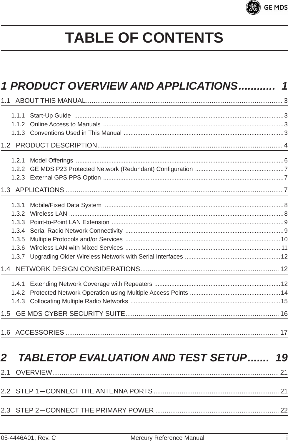
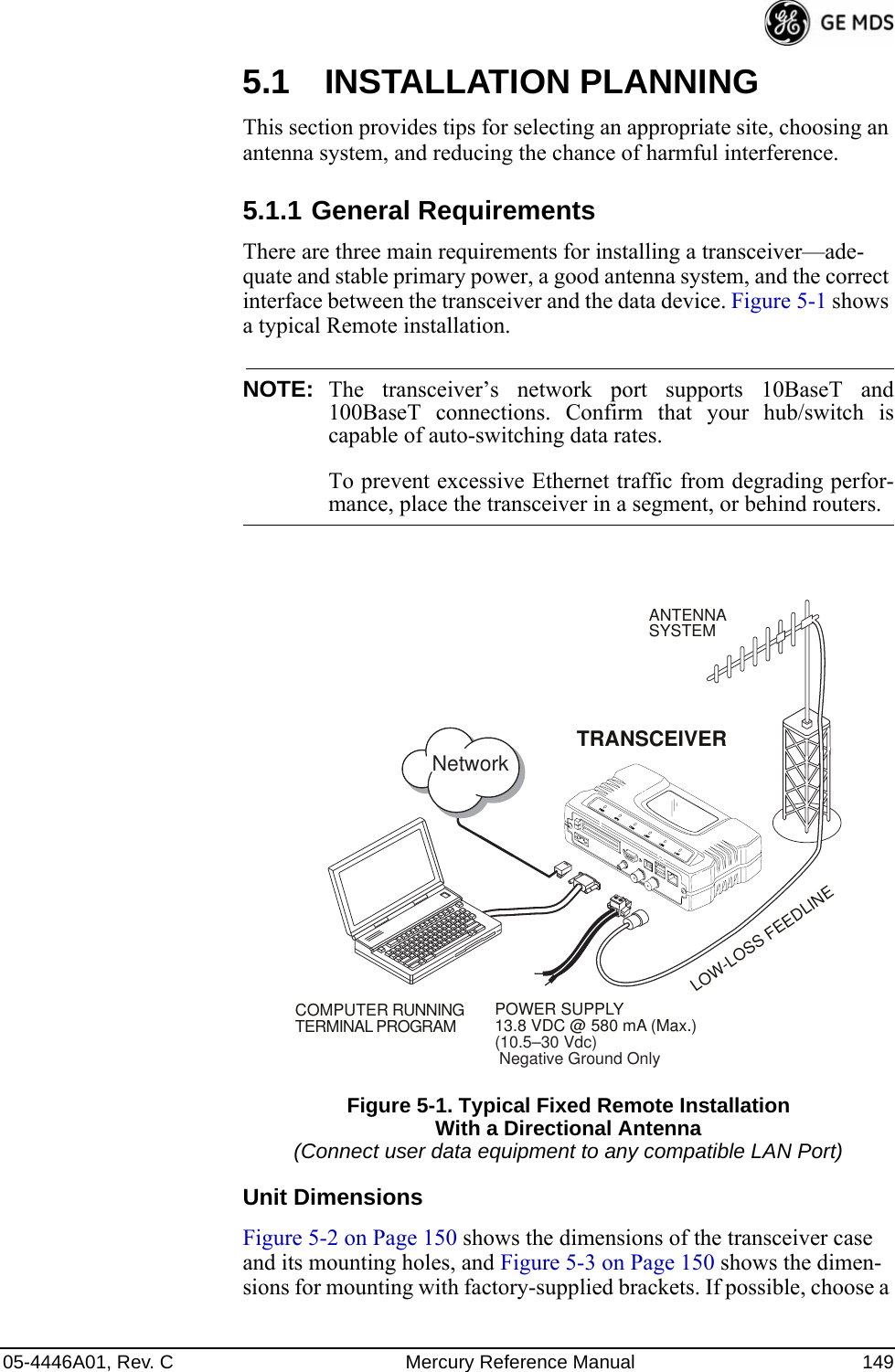
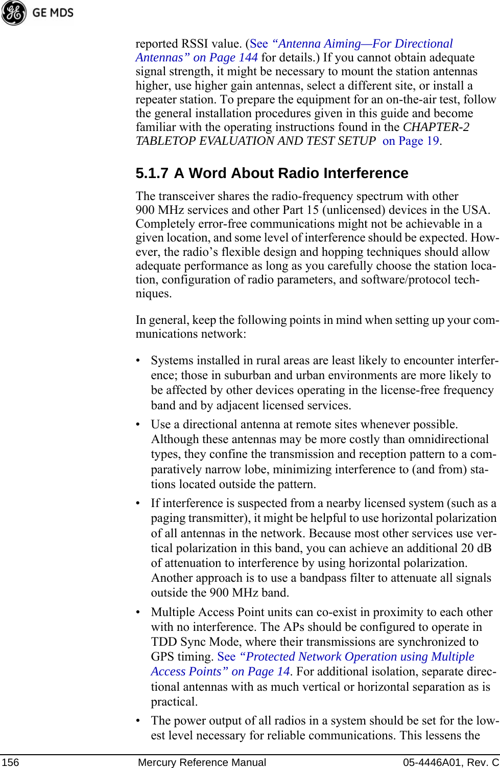
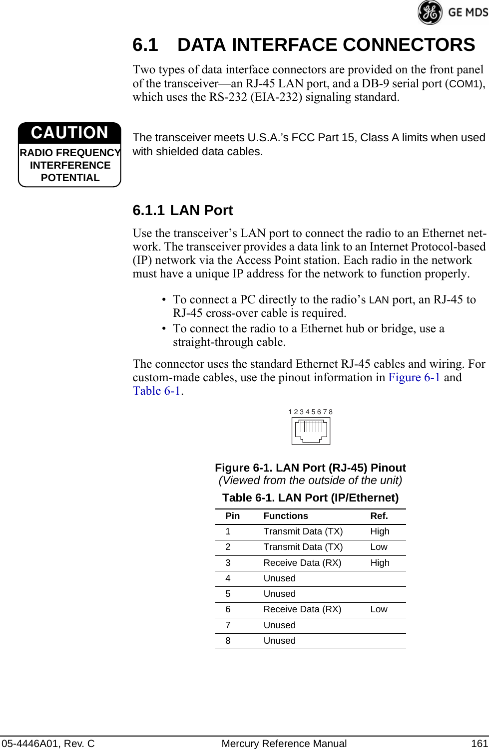
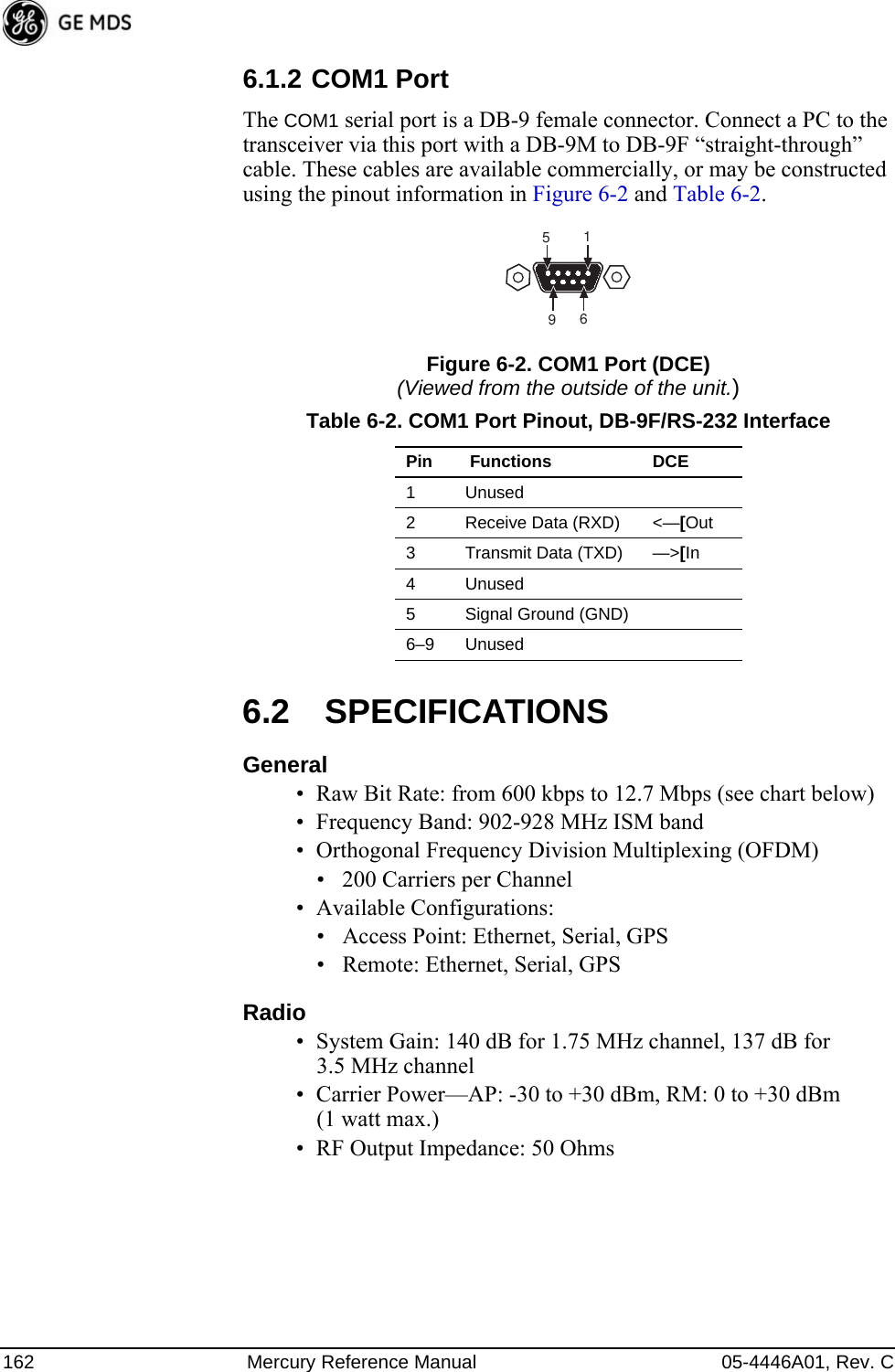
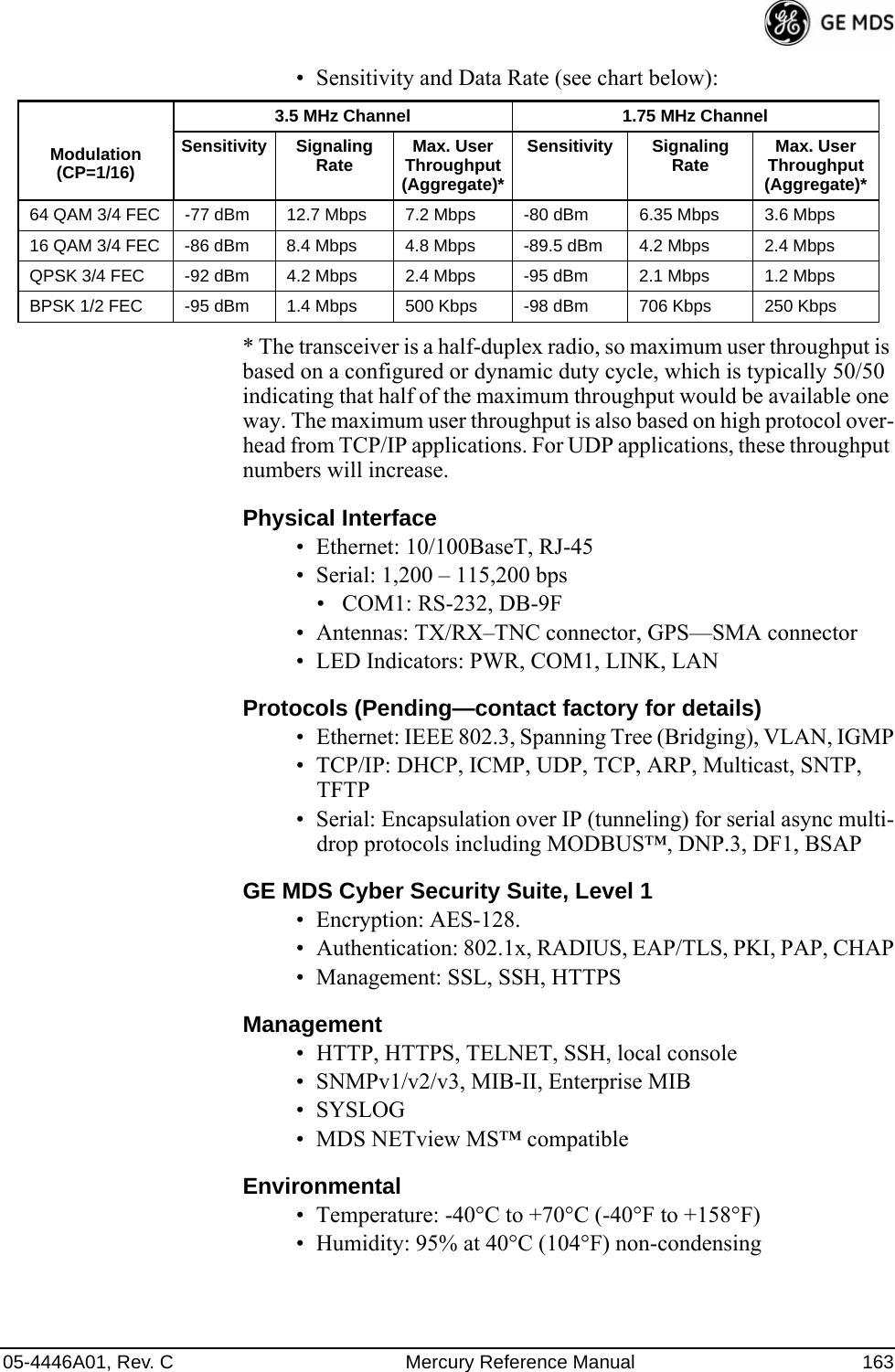
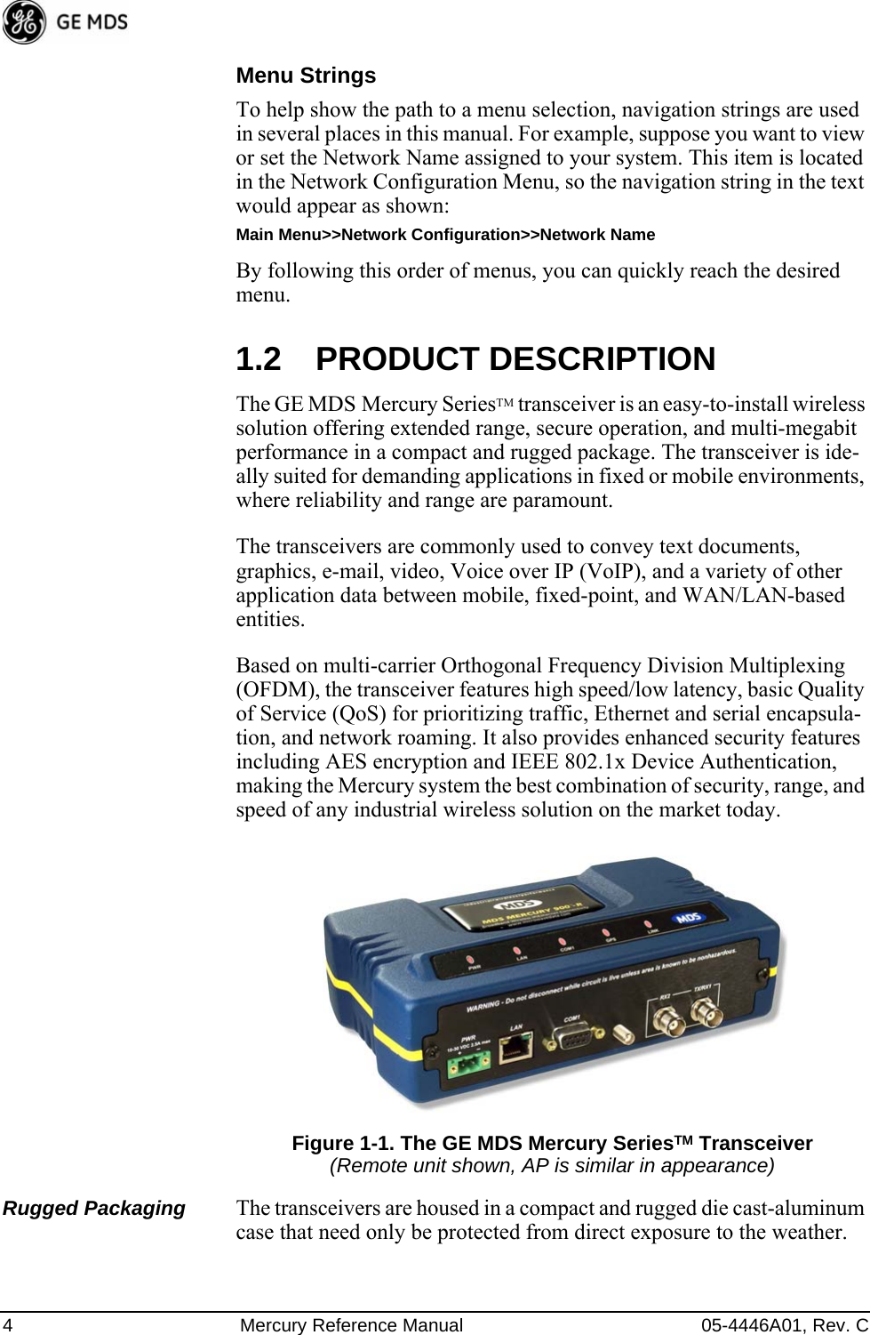
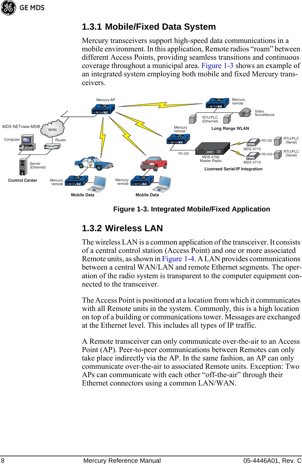
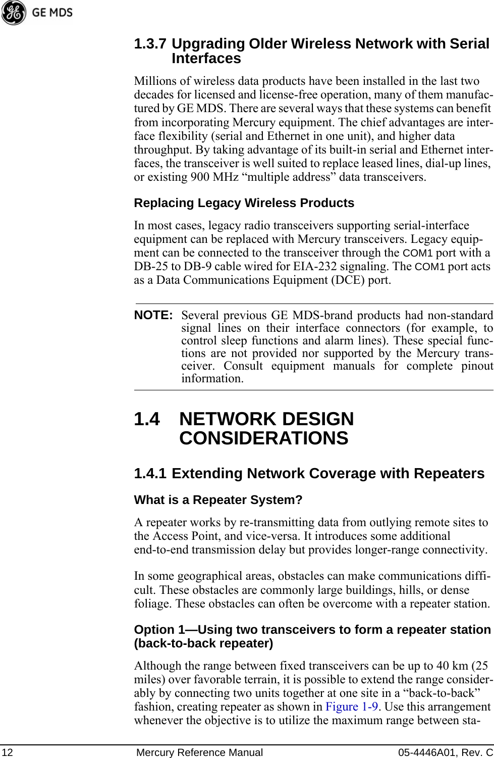
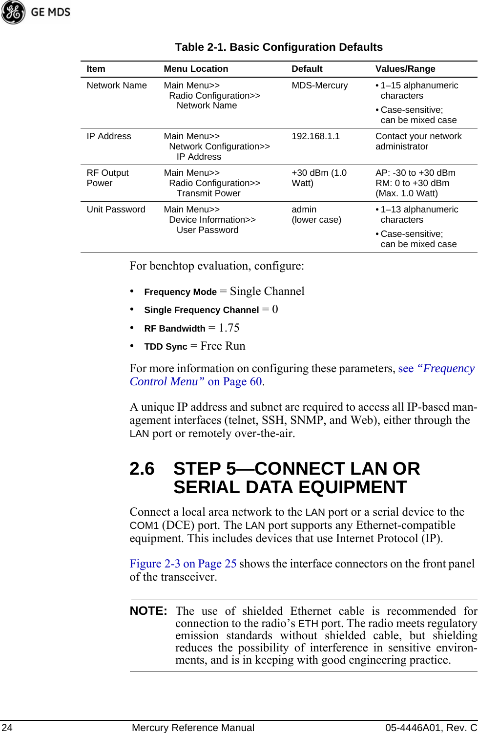
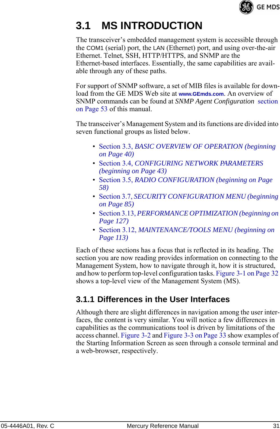
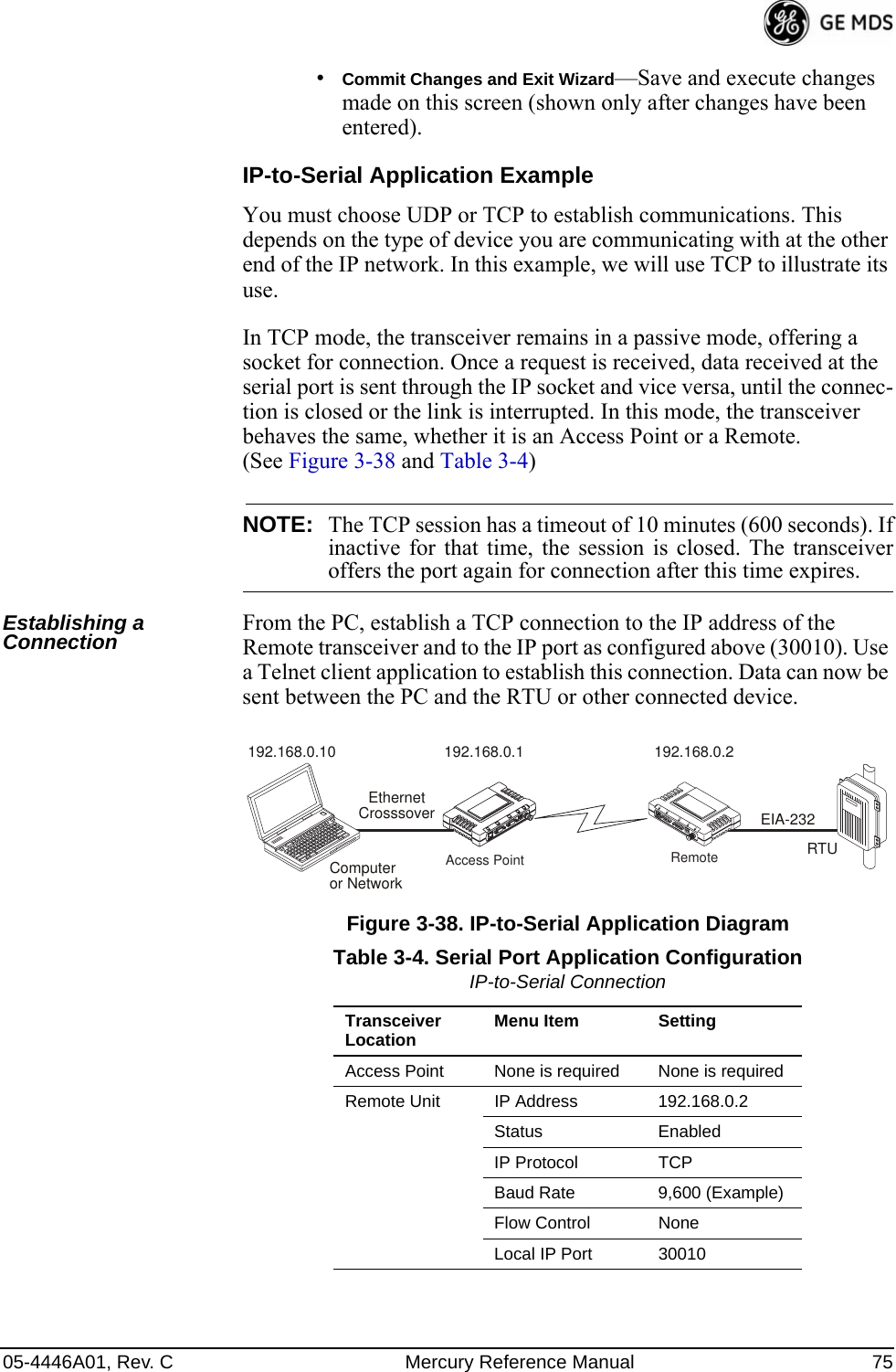
![05-4446A01, Rev. C Mercury Reference Manual 31.1 ABOUT THIS MANUALThis Reference Manual is one of two publications provided for users of the Mercury SeriesTM transceiver system. It contains detailed product information, an overview of common applications, a screen-by-screen review of the menu system, technical specifications, suggested settings for various scenarios, and detailed troubleshooting information. This manual should be available to all personnel responsible for network design, setup, commissioning and troubleshooting.1.1.1 Start-Up GuideThe Mercury Series Start-Up Guide (Part No. 05-4558A01) is a com-panion publication to the Reference Manual. It is a smaller book, with a specific purpose—to guide an installer in the basic steps for getting a transceiver on the air and communicating with other units in a network. It provides only the essential information installers require for getting their equipment up and running in the shortest time possible.1.1.2 Online Access to ManualsIn addition to printed manuals, many users need access to documents electronically. This is especially useful when you need to access docu-mentation while traveling, or want to share a document with another user in the field. Electronic documents also allow searching for a spe-cific term or subject, especially in larger manuals.Access manuals for our equipment anytime from our Web site at www.GEmds.com. Simply click the Downloads tab at the top of the home page and select Product Manuals from the drop-down list. A search window appears to help you locate the manual you need.Online manuals are provided as PDF files in the Adobe® Acrobat® stan-dard. If necessary, download the free reader for PDF files from www.adobe.com.1.1.3 Conventions Used in This ManualOn-Screen Menu ItemsOn-screen menu items or command entries are presented in a distinctive font to set them apart from regular text (for example: Network Name, IP Address, Password). You will find this font most often in Chapter 3, where the menu system is discussed in detail. When variable settings or a range of options are available for a menu option, the items are pre-sented inside brackets, with the default setting (if any) shown last after a semicolon:[available settings or range; default setting]](https://usermanual.wiki/GE-MDS/DS-MERCURY3650.User-manual/User-Guide-987144-Page-11.png)
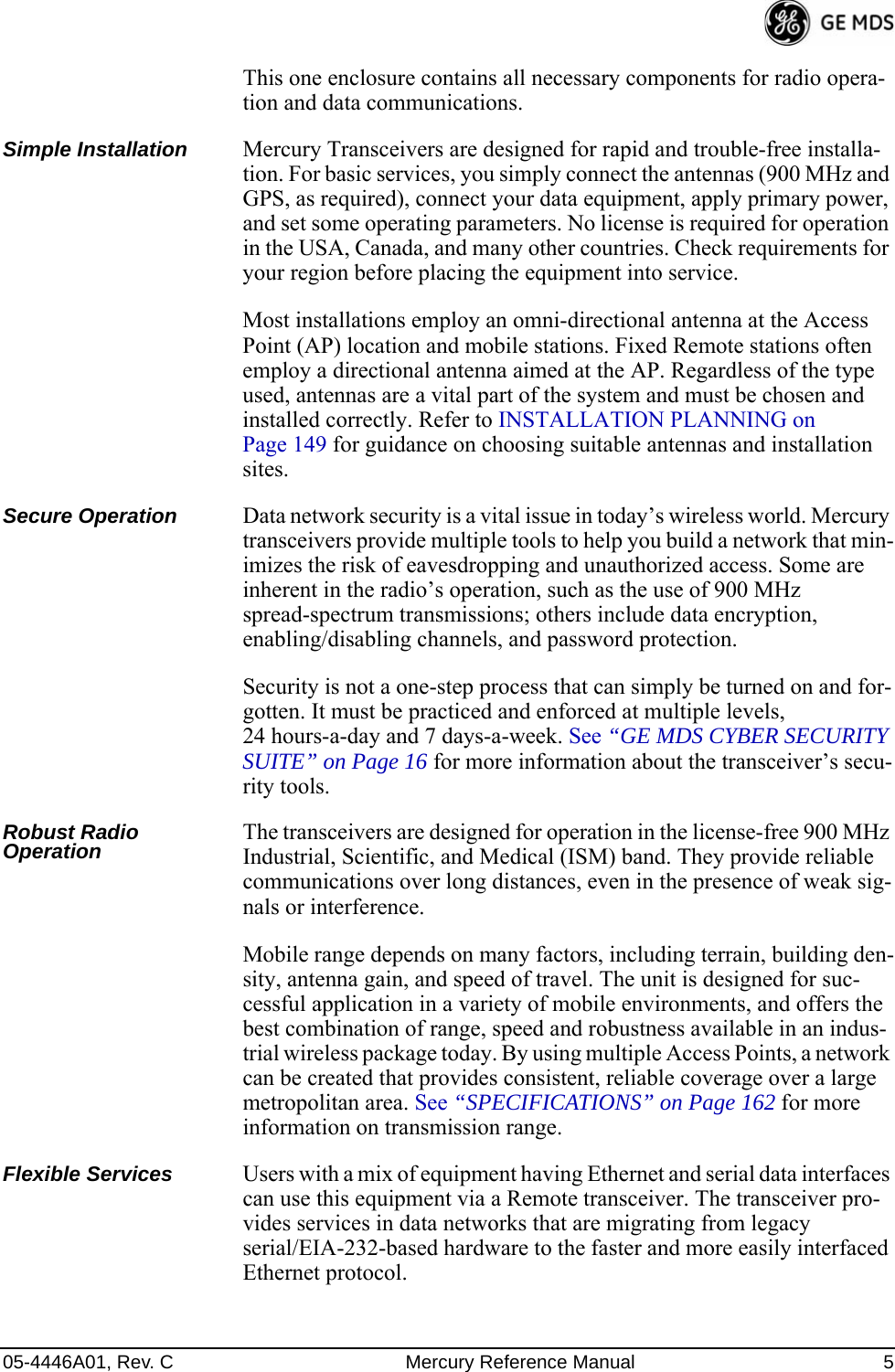
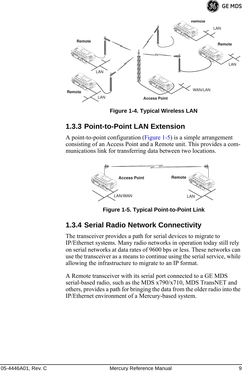
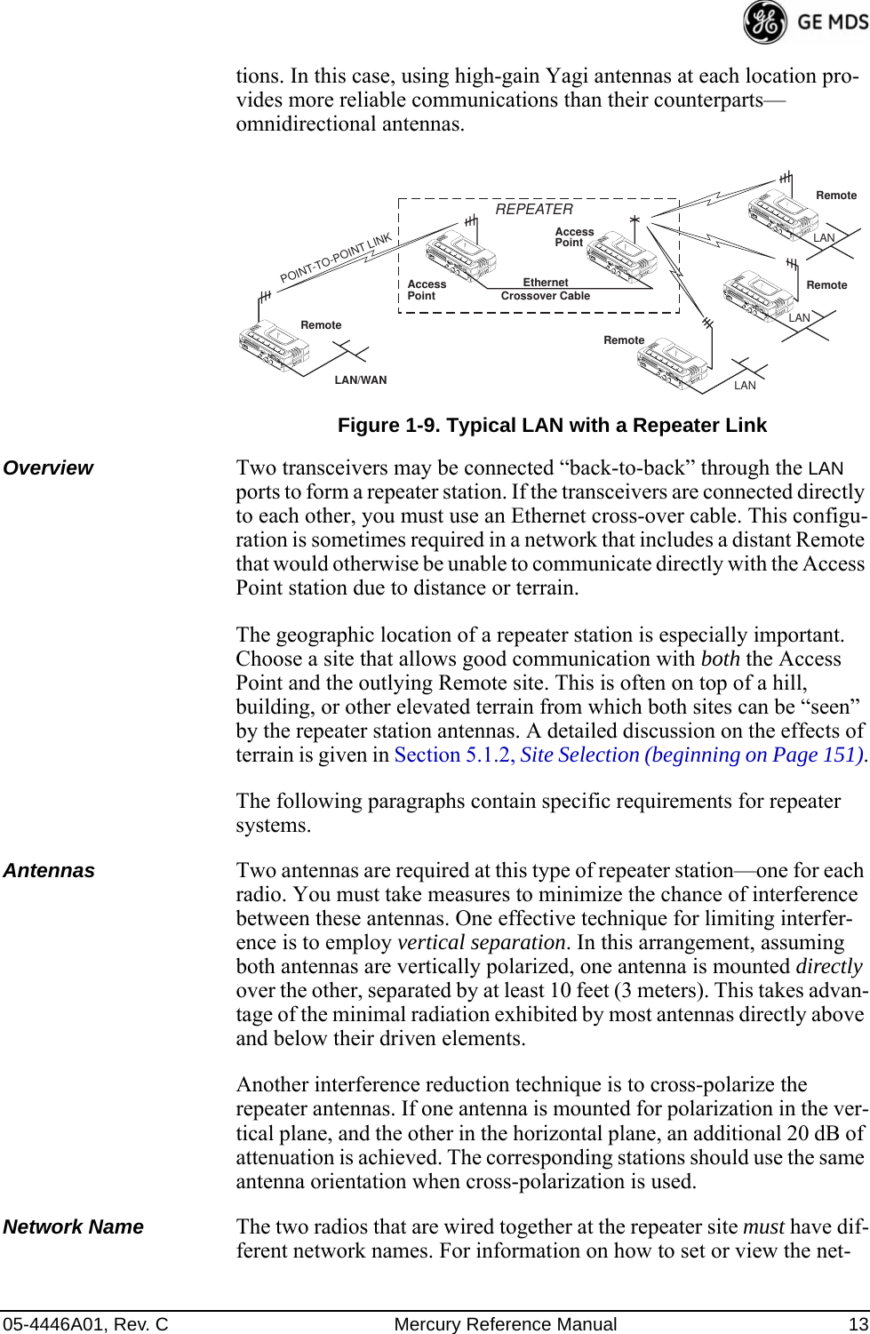
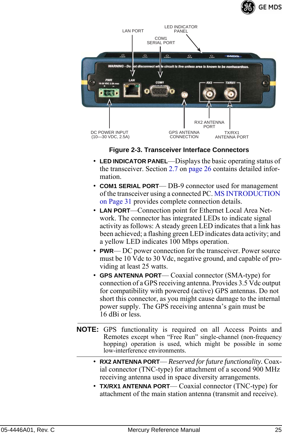

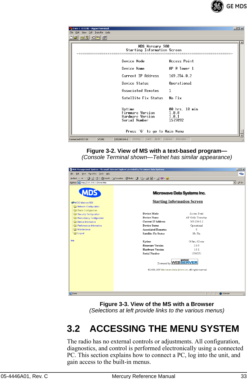
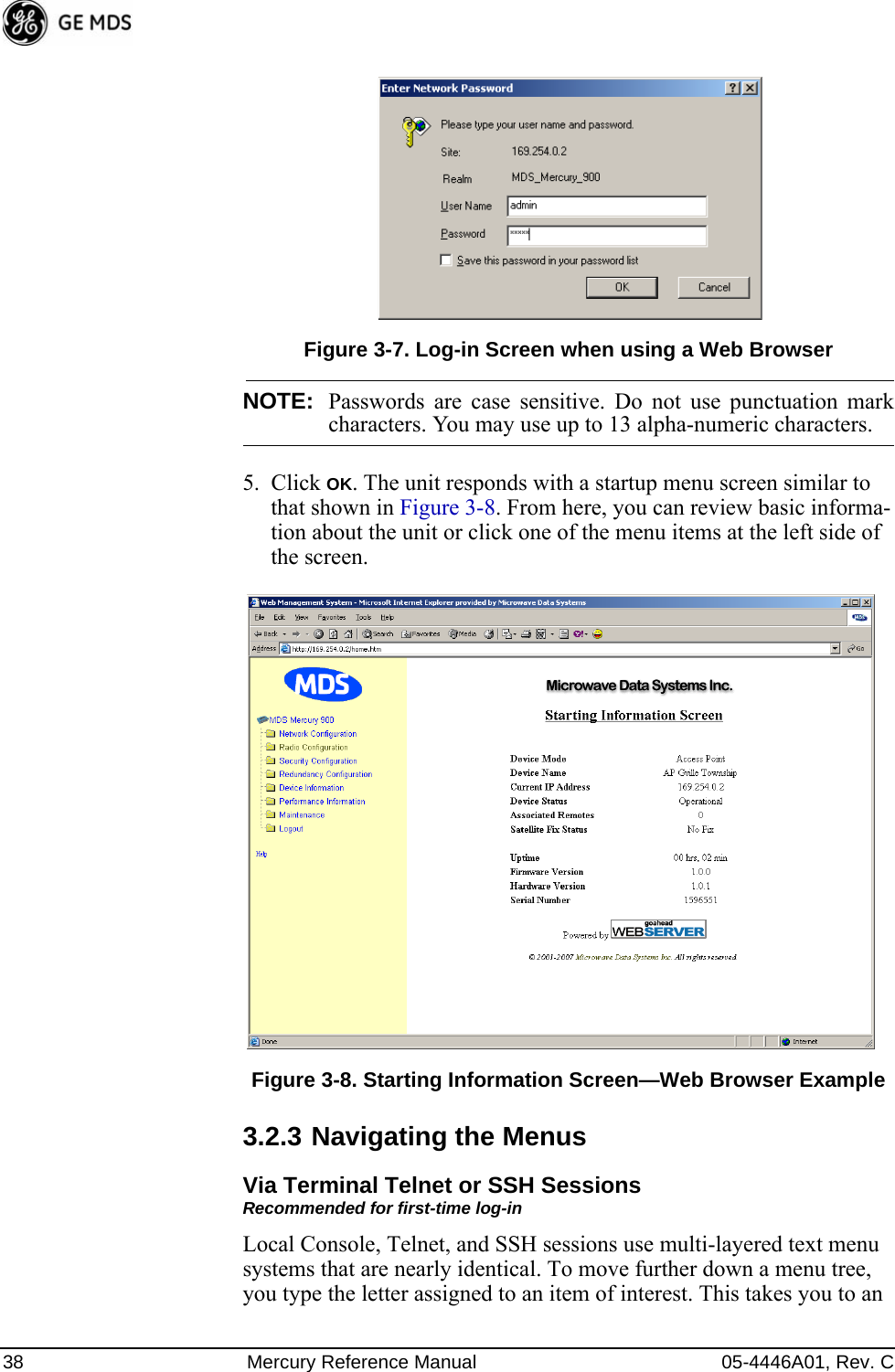
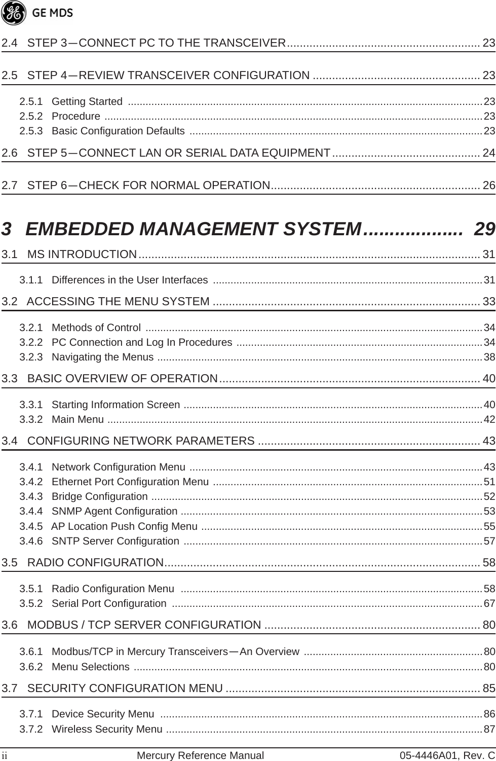
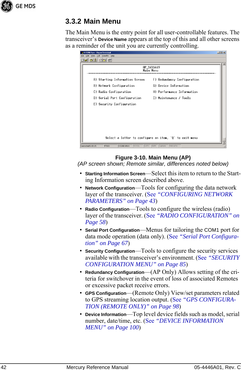
![40 Mercury Reference Manual 05-4446A01, Rev. CNOTE: In the menu descriptions that follow, parameter options/range,and any default values are displayed at the end of the textbetween square brackets. Note that the default setting isalways shown after a semicolon: [available settings or range; default setting]3.3 BASIC OVERVIEW OF OPERATION3.3.1 Starting Information ScreenOnce you have logged into the Management System, the Starting Infor-mation Screen (Figure 3-9) appears with an overview of the transceiver and its current operating conditions. Figure 3-9. Starting Information Screen(AP screen shown; Remote similar, differences noted below)•Device Mode—Operating mode of the unit as it relates to the radio network.•Device Name—This is a user-defined parameter that appears in the heading of all pages. (To change it, see Network Configura-tion Menu on Page 43.)•Current IP Address—Unit’s IP address [169.254.0.2]•Device Status—Condition of the unit’s operation as follows:At Access Point:•Operational—Unit operating normally.•Initializing—This is the first phase after boot-up.•Synchronizing—Unit is waiting for the GPS receiver to obtain a satellite fix and for its internal clock to synchronize to the GPS timing signals.](https://usermanual.wiki/GE-MDS/DS-MERCURY3650.User-manual/User-Guide-987144-Page-48.png)
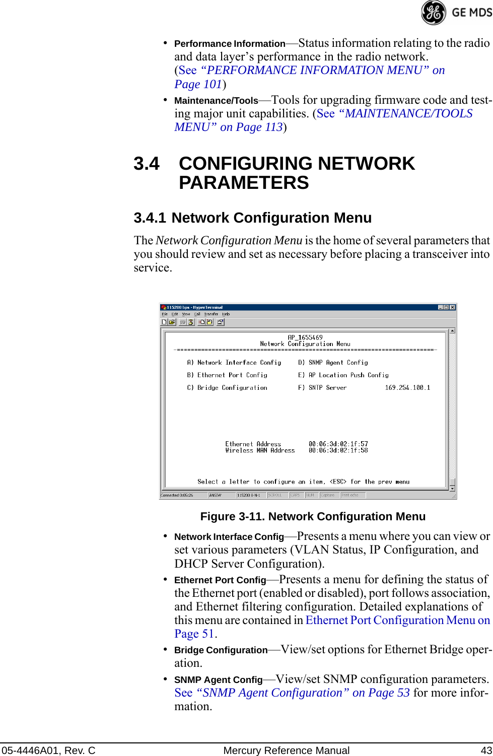
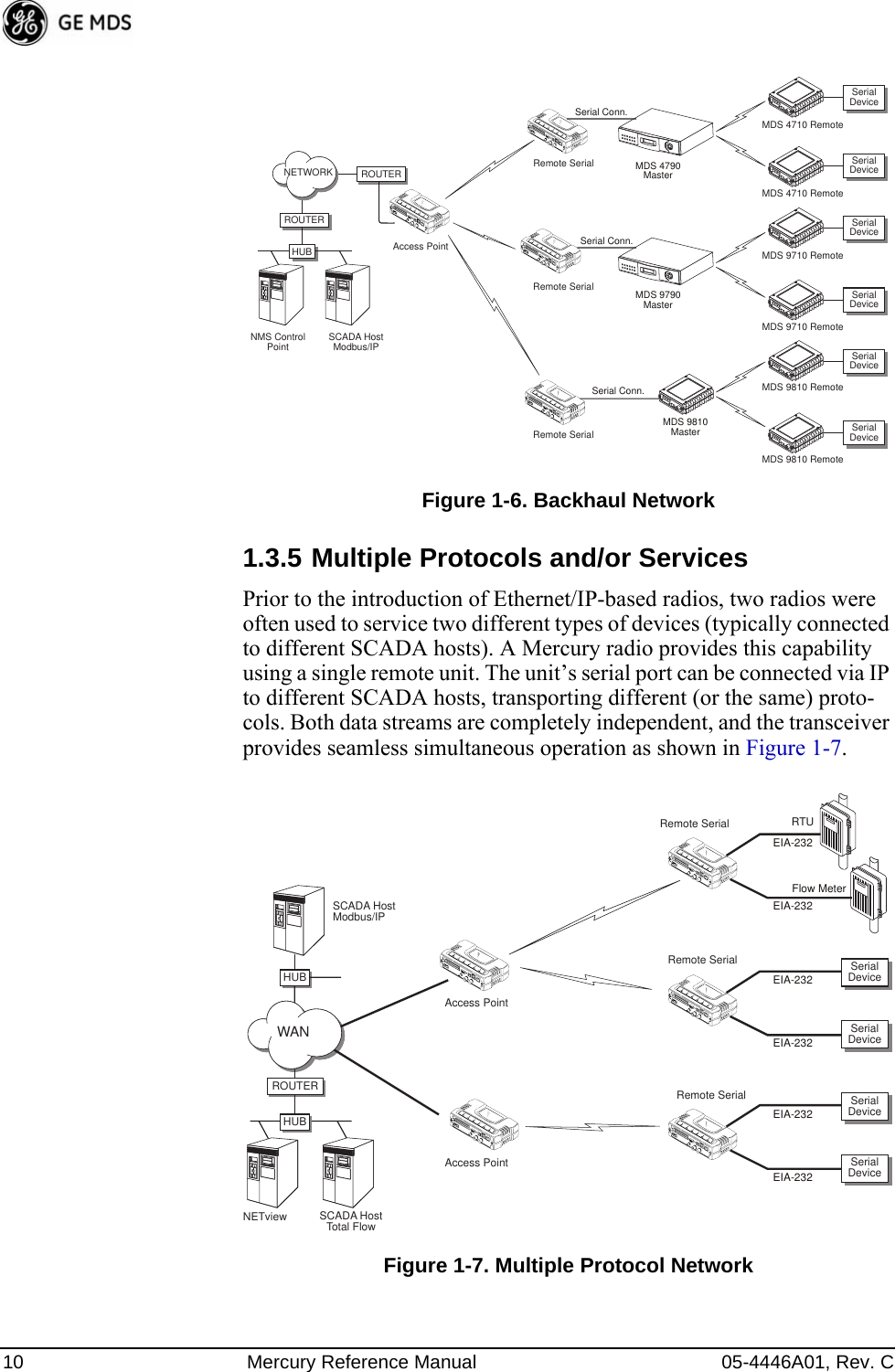
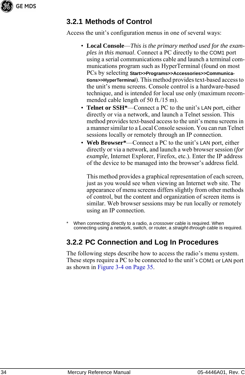
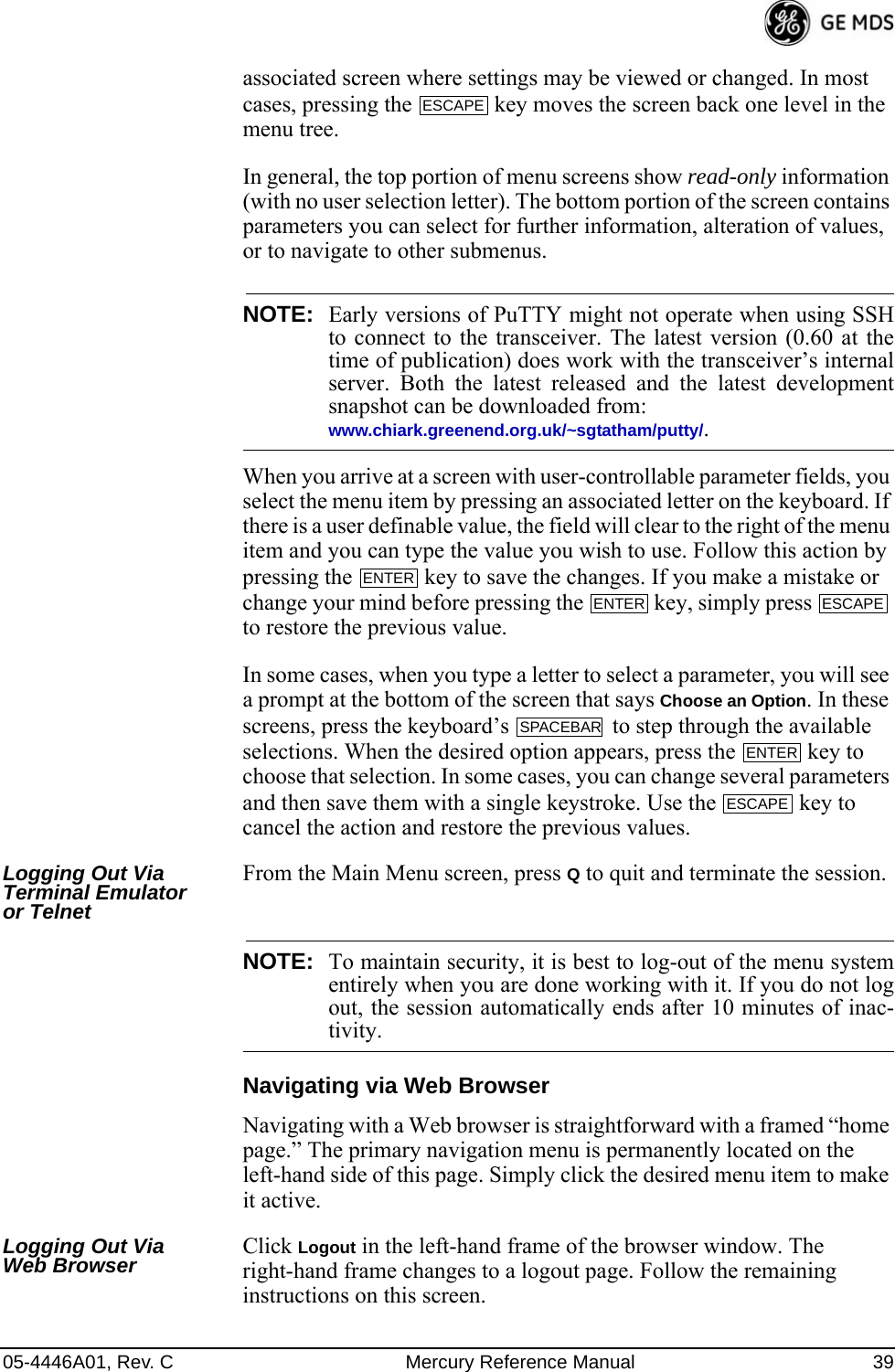
![44 Mercury Reference Manual 05-4446A01, Rev. C•AP Location Push Config—Presents a submenu for configuring an AP to automatically force connected remotes to receive the AP Locations file from the AP. See “AP Location Push Config Menu” on Page 55 for details.•SNTP Server—Address of SNTP server (RFC 2030) from which the transceiver will automatically get the time-of-day. You can also manually set the date and time. A Mercury unit tries to get the time and date from the SNTP server only if an IP address is configured. It will continue to retry every minute until it suc-ceeds. The transceivers use UTC (Universal Time Coordinated) with a configurable time offset. [0]NOTE: The Mercury gets time of day data from the GPS receiver if thereceiver gets a satellite fix.Network Interface Configuration SubmenuInvisible place holderFigure 3-12. Network Interface Configuration Submenu•VLAN Status—This selection is used to enable or disable virtual LAN operation. For details, refer to VLAN Configuration Menu on Page 45. [enable, disabled; disabled]•IP Configuration—This selection presents a submenu for config-uring the local IP address of the transceiver. Detailed explana-tions are provided in the section titled IP Configuration Menu on Page 50.•DHCP Server Config—Menu for configuration of DHCP services by the Access Point. DHCP provides “on-the-fly” IP address assignments to other LAN devices, including Mercury Series units. For details, refer to DHCP Server Configuration (Data and Mgmt) on Page 48.](https://usermanual.wiki/GE-MDS/DS-MERCURY3650.User-manual/User-Guide-987144-Page-52.png)
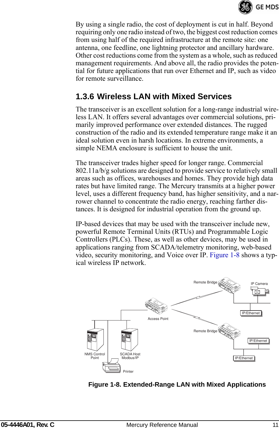
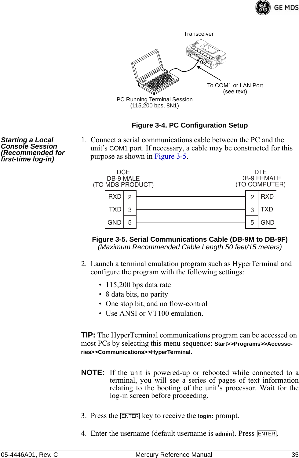
![46 Mercury Reference Manual 05-4446A01, Rev. CNetwork Interface Configuration Menu—VLAN ItemsInvisible place holderFigure 3-13. VLAN Configuration Menu•VLAN Status—Defines whether the radio handles Ethernet frames in “extended” 802.1Q mode or in “normal” mode in the Ethernet port. If configured with a trunk port, the Mercury passes all tagged traffic regardless of the VLAN ID. The Mer-cury only uses the Data VLAN ID parameter when the ETH port is configured as an Access Port.[enabled, disabled; disabled]•VLAN Ethport Mode—Defines if the Ethernet port acts as a trunk port or as an access port. Auto mode defines the port as a trunk port in an AP, or an access port in a Remote radio. [Auto, Trunk, Access; Auto]•Management VLAN ID—Defines the VLAN ID for traffic directed to the radio itself, other than the terminal server process. This VLAN ID is used for filtering and for tagging purposes. [1-4094; 2]•Data VLAN ID—Defines the VLAN ID assigned to traffic directed to and from the Ethernet port and the terminal server process in the radio. This VLAN ID is used for filtering and tagging pur-poses. [1-4094; 3]•Default Route IF—Defines the VLAN that contains the default gateway in the radio. [MGMT, DATA; MGMT]•Management VLAN Mode—Applies the VLAN tag to management frames. [Tagged, Native; Tagged].•Management VLAN Subnet Config—Presents a screen where you can set the IP Address Mode, Static IP Address, and Static IP Netmask (see Figure 3-14 on Page 47).•DHCP Server Config (Mgmt)—Presents a screen where you can view or set the DHCP server status and address information for management functions (see Figure 3-15 on Page 48).](https://usermanual.wiki/GE-MDS/DS-MERCURY3650.User-manual/User-Guide-987144-Page-54.png)
![05-4446A01, Rev. C Mercury Reference Manual 47•Data VLAN Subnet Config—Presents a screen where you can view or set the IP mode and address information (see Figure 3-17 on Page 49).•DHCP Server Config (Data)—Presents a screen where you can view or set DHCP server status and address information for data functions (see Figure 3-16 on Page 49).Management VLAN Subnet Configuration MenuInvisible place holderFigure 3-14. Management VLAN Subnet Configuration MenuNOTE: Changes to any of the following parameters while communi-cating over the network (LAN or over-the-air) might cause aloss of communication with the unit you are configuring. Youmust re-establish communication using the new IP address.•IP Address Mode—Defines the source of the IP address of this device. Only static IP addressing mode is available when VLAN Status is enabled. [Static, Dynamic; Static]•Static IP Address—The IPv4 local IP address. [192.168.1.1]•Static IP Netmask—The IPv4 local subnet mask. This value is used when the radio attempts to send a locally initiated message, either from the terminal server, or from a management process. [255.255.0.0]The lower three lines of the screen (Current IP Address, Current IP Netmask, Current IP Gateway) show the current addressing configured at the trans-ceiver. Current IP Gateway only displays on this screen if Default Route IF on the Network Interface Config menu (Figure 3-13 on Page 46) is set to Management.Selecting option I from the menu in Figure 3-13 on Page 46 displays the screen shown in Figure 3-17 on Page 49. Note that the IP address is dif-ferent even though it is the same physical unit. This is because this IP address is defined for a different VLAN.](https://usermanual.wiki/GE-MDS/DS-MERCURY3650.User-manual/User-Guide-987144-Page-55.png)
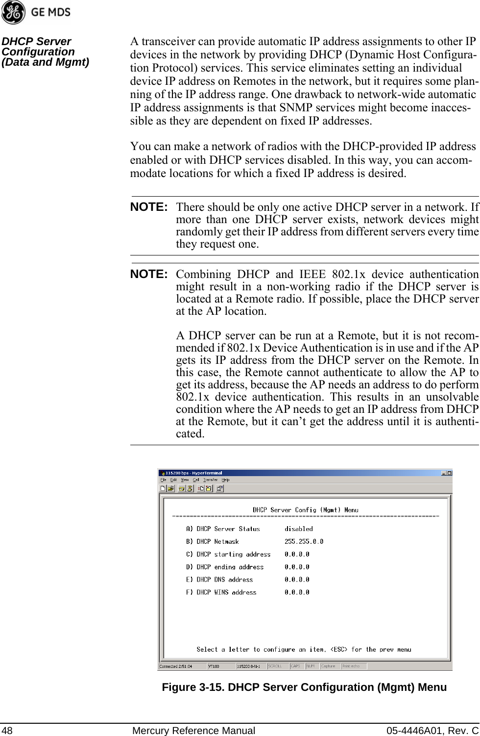
![05-4446A01, Rev. C Mercury Reference Manual 49Invisible place holderFigure 3-16. DHCP Server Configuration (Data) Menu•DHCP Server Status—Enable/Disable the response to DHCP requests to assign an IP address. [Disabled/Enabled; Disabled]•DHCP Netmask—IP netmask to be assigned along with the IP address in response to a DHCP request. [0.0.0.0]•DHCP starting address—Lowest IP address in the range of addresses provided by this device. [0.0.0.0]•DHCP ending address—Highest IP address in the range of addresses provided by this device. A maximum of 256 addresses is allowed in this range. [0.0.0.0]•DHCP DNS address—Domain Name Server address provided by this service.•DHCP WINS address—Windows Internet Naming Service server address provided by this service.Data VLAN Subnet Configuration Menu Invisible place holderFigure 3-17. Data VLAN Subnet Configuration Menu](https://usermanual.wiki/GE-MDS/DS-MERCURY3650.User-manual/User-Guide-987144-Page-57.png)
![50 Mercury Reference Manual 05-4446A01, Rev. C•IP Address Mode—Defines the source of this device’s IP address. Only static IP addressing mode is available when VLAN Status is enabled [Static; Static]•IP Address—The IPv4 local IP address. [192.168.1.1]•IP Netmask—The IPv4 local subnet mask. This value is used when the radio attempts to send a locally initiated message, from either the terminal server or the management process. [255.255.0.0]•IP Gateway—The IPv4 address of the default gateway device, typically a router. [0.0.0.0]The lower three lines of the screen (Current IP Address, Current IP Netmask, and Current IP Gateway) show the current addressing configured at the transceiver. Current IP Gateway only displays on this screen if Default Route IF on the Network Interface Config menu (Figure 3-13 on Page 46) is set to Data.Invisible place holderIP Configuration MenuFigure 3-18. IP Configuration MenuCAUTION: Changes to the following parameters while communicatingover the network (LAN or over-the-air) might cause a loss ofcommunication with the unit being configured. You mustre-establish communication using the new IP address.•IP Address Mode—Defines the source of this device’s IP address. [Static, Dynamic; Static]•Static IP Address (User Review Recommended)—Essential for connec-tivity to the transceiver’s MS using the LAN port. Enter any valid IP address that is unique within the network. This field is unnec-essary if DHCP is enabled. [192.168.1.1]](https://usermanual.wiki/GE-MDS/DS-MERCURY3650.User-manual/User-Guide-987144-Page-58.png)
![05-4446A01, Rev. C Mercury Reference Manual 51•Static IP Netmask—The IPv4 local subnet mask. This field is unnecessary if DHCP is enabled. [255.255.0.0]•Static IP Gateway—The IPv4 address of the network gateway device, typically a router. This field is unnecessary if DHCP is enabled. [0.0.0.0]The lower three items on the screen (Current IP Address, Net-mask and Gateway) show the actual addressing at the trans-ceiver whether it was obtained from static configuration or from a DHCP server.3.4.2 Ethernet Port Configuration MenuThe transceiver allows for special control of the Ethernet interface, to allow traffic awareness and availability of the backhaul network for redundancy purposes.NOTE: The transceiver’s network port supports 10BaseT and100BaseT connections. Confirm that your hub/switch iscapable of auto-switching data rates.To prevent excessive Ethernet traffic from degrading perfor-mance, place the transceiver in a segment, or behind routers.Figure 3-19. Ethernet Port Configuration Menu•Ethernet Port Enable—Allows enabling/disabling Ethernet traffic for security purposes. Setting it to enabled enables the port. [enabled, disabled; enabled]•Ethernet Port Phy Rate—The Ethernet port’s configured speed.•Eth Port Follows Association (Remote Only)—When enabled, the Ethernet port is disabled when not associated. [enabled, disabled; disabled]](https://usermanual.wiki/GE-MDS/DS-MERCURY3650.User-manual/User-Guide-987144-Page-59.png)
![52 Mercury Reference Manual 05-4446A01, Rev. C•Ethernet Filtering Config—Allows enabling/disabling filtering and specifying of Ethernet addresses.Ethernet Filtering Configuration MenuInvisible place holderFigure 3-20. Ethernet Filtering Configuration Menu•Enable Filtering—Activates Ethernet filtering.[enabled, disabled; disabled]•Address 1, 2, 3, 4—Ethernet address fields. When filtering is enabled, the Mercury only accepts traffic on its Ethernet port from the configured addresses. [Valid IP address string]3.4.3 Bridge Configuration Invisible place holderFigure 3-21. Bridge Configuration Menu•Bridge Priority—View/set the priority of the bridge in the span-ning tree. [0-65535; 32769]](https://usermanual.wiki/GE-MDS/DS-MERCURY3650.User-manual/User-Guide-987144-Page-60.png)
![05-4446A01, Rev. C Mercury Reference Manual 53•Bridge Hello Time—View/set spanning tree hello time. This parameter affects how often the bridge sends a spanning tree Bridge Protocol Data Unit (BPDU). [1-10 seconds; 2 seconds]•Bridge Forward Delay—View/set spanning tree forwarding delay. Affects how long the bridge spends listening and learning after initialization. [4-30 seconds; 5 seconds].3.4.4 SNMP Agent ConfigurationThe transceiver contains over 100 custom SNMP-manageable objects as well as the IETF standard RFC1213 for protocol statistics, also known as MIB II. You can use off-the-shelf SNMP managers to access the transceiver’s SNMP Agent’s MIB, such as Castle Rock Computing SNMPc™ and Hewlett Packard OpenView™. The transceiver’s SNMP agent supports SNMPv1, v2, and v3.The objects are split into nine MIB files for use with your SNMP man-ager. There are textual conventions, common files, and specific files. This allows the flexibility to change areas of the MIB and not affect other existing installations or customers.•msdreg.mib—MDS sub-tree registrations•mds_comm.mib—MDS Common MIB definitions for objects and events common to the entire product family•mercury_reg.mib—MDS sub-tree registrations•mercurytrv1.mib—SNMPv1 enterprise-specific traps•mercurytrv2.mib—SNMPv2 enterprise-specific traps•mercury_comm.mib— MIB definitions for objects and events common to the entire Mercury Series•mercury_ap.mib—MIB definitions for objects and events for an Access Point transceiver•mercury_rem.mib—Definitions for objects and events for a Remote radio•mercury_sec.mib—For security management of the radio systemNOTE: SNMP management requires that the proper IP address,network, and gateway addresses are configured in each associ-ated network transceiver. In addition, some management systems might require that youcompile the MIB files in the order shown above.](https://usermanual.wiki/GE-MDS/DS-MERCURY3650.User-manual/User-Guide-987144-Page-61.png)
![54 Mercury Reference Manual 05-4446A01, Rev. CInvisible place holderFigure 3-22. SNMP Server Configuration MenuThis menu provides configuration and control of vital SNMP functions.•Read Community String—SNMP community name with SNMPv1/SNMPv2c read access. This string can contain up to 30 alpha-numeric characters.•Write Community String—SNMP community name with SNMPv1/SNMPv2c write access. This string can contain up to 30 alpha-numeric characters.•Trap Community String—SNMP community name with SNMPv1/SNMPv2c trap access. This string can contain up to 30 alpha-numeric characters.•V3 Authentication Password—Authentication password stored in flash memory. This is used when the Agent is managing pass-words locally (or initially for all cases on reboot). This is the SNMPv3 password used for Authentication (currently, only MD5 is supported). This string can contain up to 30 alpha-numeric characters.•V3 Privacy Password—Privacy password stored in flash memory. Used when the SNMP Agent is managing passwords locally (or initially for all cases on reboot). This is the SNMPv3 password used for privacy (DES encryption). This string can contain between 8 and 30 alpha-numeric characters.•SNMP Mode—This specifies the mode of operation of the radio’s SNMP Agent. The choices are: disabled, v1_only, v2_only, v3_only, v1-v2, and v1-v2-v3. If the mode is disabled, the Agent does not respond to any SNMP traffic. If the mode is v1_only, v2_only, or v3_only, the Agent responds only to that version of SNMP traffic. If the mode is v1-v2 or v1-v2-v3, the Agent responds to the specified version of SNMP traffic. [v1-v2-v3]](https://usermanual.wiki/GE-MDS/DS-MERCURY3650.User-manual/User-Guide-987144-Page-62.png)
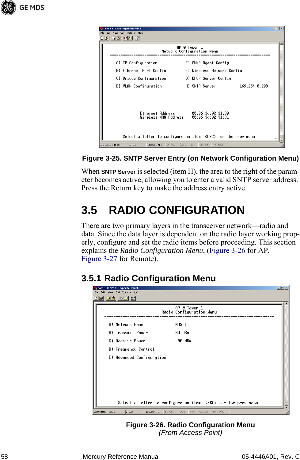
![05-4446A01, Rev. C Mercury Reference Manual 55•Trap Version—This specifies which version of SNMP is used to encode the outgoing traps. The choices are v1_traps, v2_traps, and v3_traps. When v3_traps is selected, v2-style traps are sent, but with a v3 header. [v1_traps, v2_traps, v3_traps]•Auth Traps Status—Indicates whether or not traps are generated for failed authentication of an SNMP PDU. [Disabled/Enabled; Disabled]•SNMP V3 Passwords—Determines whether v3 passwords are managed locally or via an SNMP Manager. The different behav-iors of the Agent, depending on the mode selected, are described in SNMP Mode above.•Trap Manager #1–#4— Table of up to four locations on the net-work to which traps are sent. [Any standard IP address]NOTE: The number in the upper right-hand corner of the screen is theSNMP Agent’s SNMPv3 Engine ID. Some SNMP Managersmay need to know this ID in order interface with the trans-ceiver’s SNMP Agent. The ID only appears on the screenwhen SNMP Mode is either v1-v2-v3 or v3_only.NOTE: For more SNMP information, see “NOTES ON SNMP” onPage 165.3.4.5 AP Location Push Config MenuThis menu configures the AP for updating connected remotes with the AP Locations File loaded on the AP.Invisible place holderFigure 3-23. AP Location Push Config Menu•TFTP Host Address—IP address of the TFTP server that holds the AP locations file. [any valid IP address; 0.0.0.0]•Transfer Options—Menu for configuring the TFTP transfer.](https://usermanual.wiki/GE-MDS/DS-MERCURY3650.User-manual/User-Guide-987144-Page-63.png)
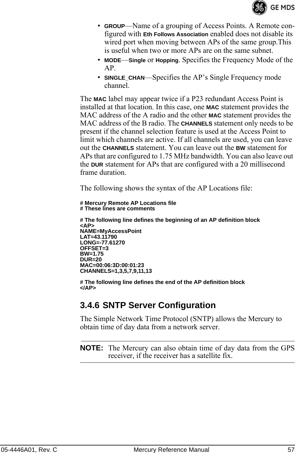
![56 Mercury Reference Manual 05-4446A01, Rev. C•AP Locations Filename—Name of the AP Locations file on the server. [any valid filename string; ap_locations.txt]•Auto AP Location Download—A setting to force connected remotes to download immediately the AP Locations file on the AP. Remotes that associate to an AP with this feature will also download the file.•Retrieve Text File—Download AP Locations text file from the server.•Send Text File—Upload the local AP Locations file to the server.•View AP Location File—Allows on-screen review of the AP Loca-tions file. An example screen is shown in Figure 3-24.Invisible place holderFigure 3-24. AP Location Text FileAP Locations File Syntax and GuidelinesThe AP Locations file is used by the Remote radio to determine which Access Point to connect to when operating in Hopping w/ Hand-offs mode. The AP Locations file is a simple text file containing information about the location and configuration of all Access Points that the Remote can associate with. The file is filled in by creating “AP definition blocks” using tags and labels. The <AP> tag is used to begin a definition block and the </AP> tag ends the block. Within the block, you can declare sev-eral parameters using a LABEL=VALUE syntax. The possible labels are: •NAME—The name of the AP. Typically set to the Device Name configured on the AP•LAT—GPS Latitude of the AP in decimal degrees•LONG—GPS Longitude of the AP in decimal degrees•OFFSET—Pattern Offset configured on the AP•BW—Bandwidth (1.75 or 3.5) configured on the AP•DUR—Frame duration (10 or 20) configured on the AP•MAC—The “Wireless MAN Address” configured on the AP•CHANNELS—Specifies which channels are being used by the AP](https://usermanual.wiki/GE-MDS/DS-MERCURY3650.User-manual/User-Guide-987144-Page-64.png)
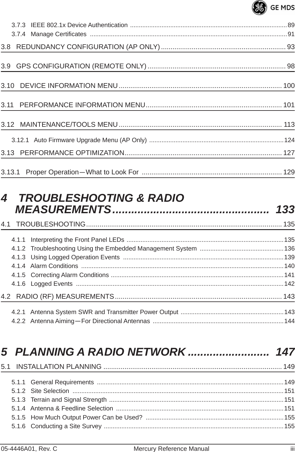
![05-4446A01, Rev. C Mercury Reference Manual 59Figure 3-27. Radio Configuration Menu(From Remote Unit)•Network Name—The user-defined name for the wireless network. [Any 40 character string; MDS-Mercury]•Transmit Power (AP Only)—Sets/displays RF power output level in dBm. This setting should reflect local regulatory limitations and losses in antenna transmission line. (See “How Much Out-put Power Can be Used?” on Page 155 for information on how to calculate this value.) [0–30; 30]•Max Transmit Power (Remote Only)—Sets/displays maximum RF power output level in dBm of the Remote. Power level is still controlled by the AP, but it is limited to the maximum level set here. This setting should reflect local regulatory limitations and losses in antenna transmission line. (See “How Much Output Power Can be Used?” on Page 155 for information on how to calculate this value.) [0–30; 30]•Receive Power (AP Only)—View/set the receiver gain setpoint for the expected strength of incoming signals from Remotes. This setting indicates at what level (in dBm) the AP expects to hear the Remote stations. A setting of -70 would set the AP receiver’s gain to a relatively low level, while a setting of -85 would be a comparatively high gain setting. [-100 to -20; -75]•Frequency Control—Opens a submenu where you can view or set frequency mode bandwidth, channel and other parameters as described in Frequency Control Menu below.•Advanced Configuration—Opens a submenu where you can view or set modulation, protection/hysteresis margins, data compres-sion, ARQ settings, and other parameters as described in Advanced Configuration Menu on Page 65.](https://usermanual.wiki/GE-MDS/DS-MERCURY3650.User-manual/User-Guide-987144-Page-67.png)
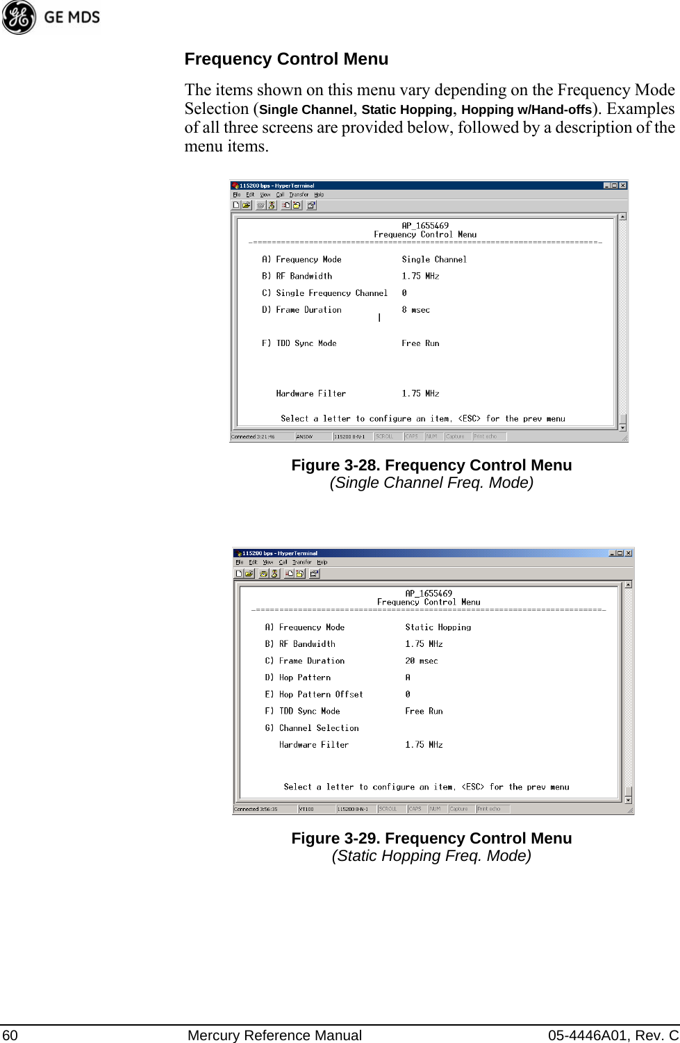
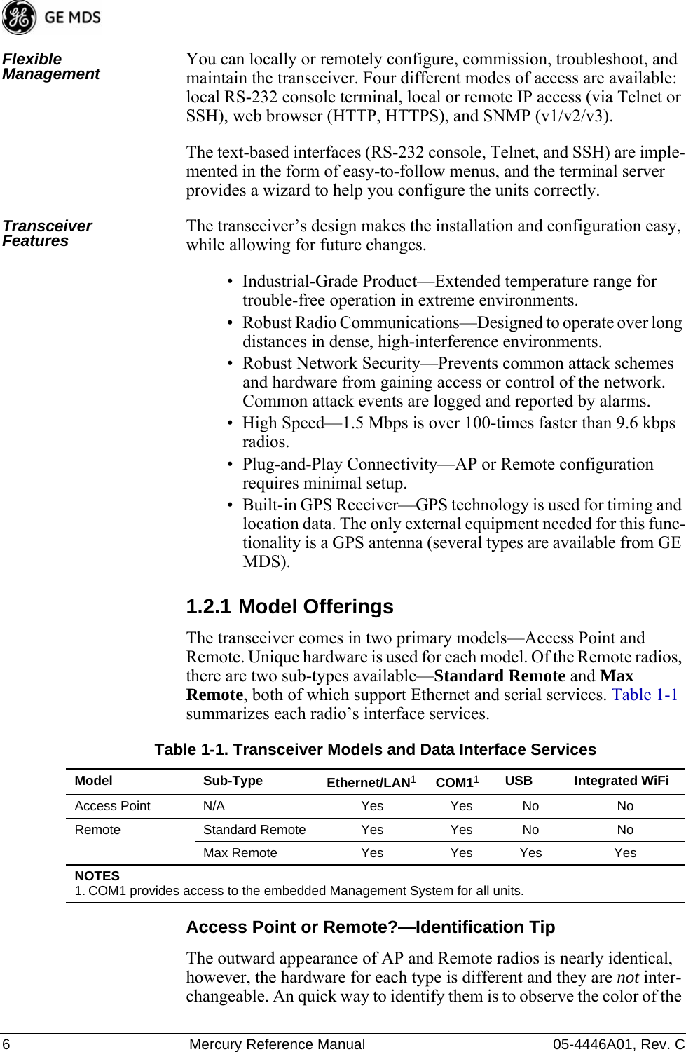
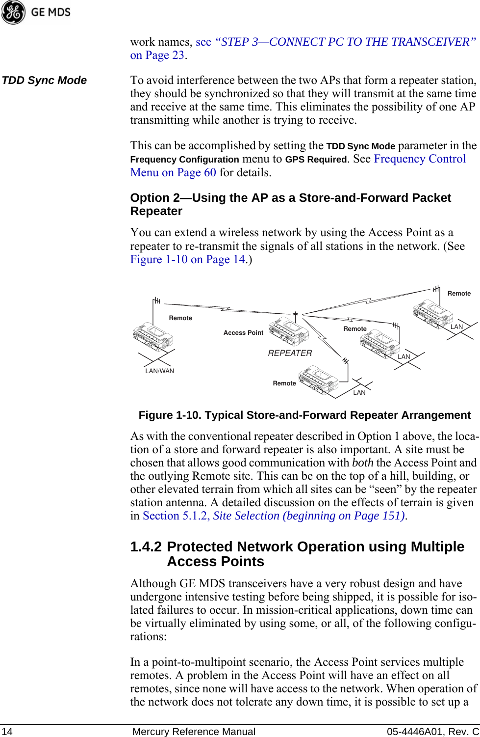
![05-4446A01, Rev. C Mercury Reference Manual 61Invisible place holderFigure 3-30. Frequency Control Menu(Hopping w/Hand-offs Freq. Mode [Remote only])•Frequency Mode—The unit can operate on one selected fre-quency or frequency hop. Remotes have the option of using a static hopping configuration or using the AP locations file to select an AP and perform hand-offs. For more information on hand-offs, see Table 3-2 on Page 64. Changing this parameter requires a radio reboot.[Static Hopping, Hopping with Hand-offs, Single Channel; Single Channel]NOTE: Frequency Mode Static Hopping on Access Points requiresTDD Sync Mode GPS Required.Channel/Frequency Allocations for Single Channel operation are shown in Table 3-1. The transceiver utilizes up to 14 chan-nels (0-13) depending on the bandwidth used (1.75 MHz or 3.5 MHz).Table 3-1. Channel/Frequency AllocationsChannel 1.75 MHz B/W 3.5 MHz B/W0 903.000000 904.0000001 904.800000 907.6000002 906.600000 911.4000003 908.600000 915.0000004 910.400000 918.6000005 912.200000 922.4000006 914.000000 926.0000007 916.0000008 917.8000009 919.600000](https://usermanual.wiki/GE-MDS/DS-MERCURY3650.User-manual/User-Guide-987144-Page-69.png)
![62 Mercury Reference Manual 05-4446A01, Rev. C•RF Bandwidth—View/set the radio’s RF operating bandwidth. Radios are factory-configured for either 1.75 MHz or 3.5 MHz maximum bandwidth. Determine the factory configuration of a radio by viewing the “CONFIG” number on the label at the bot-tom of the radio. 1.75 MHz units will have a Configuration string starting with HGA/R9N1, and 3.5 MHz units will have a string starting with HGA/R9N3.The bandwidth setting on this menu does not necessarily have to match the configured bandwidth of the radio, but it is limited by it. That is, you can set a 3.5 MHz radio to either 1.75 or 3.5, but you can only set a 1.75 MHz radio to 1.75. Note that setting a 3.5 MHz bandwidth radio to operate at 1.75 MHz bandwidth will cause a slight degradation of interference rejection capabil-ity. [1.75MHz, 3.5MHz]•Hop Pattern—Selects a pre-defined series of channels that is fol-lowed when hopping.•Hop Pattern Offset—Inserts an offset into the hop pattern that is synchronized with the GPS. For example, if the offset is 0, then the start of the pattern is aligned with the GPS timing. If the off-set is 3, then the fourth hop of the pattern is aligned with the GPS timing. All of the APs that are part of a network should use the same pattern and each one should have its own offset. In the diagram below, one Remote is configured for static hop-ping and will only associate with AP1 because they are both 10 921.40000011 923.40000012 925.20000013 927.000000Table 3-1. Channel/Frequency AllocationsChannel 1.75 MHz B/W 3.5 MHz B/W](https://usermanual.wiki/GE-MDS/DS-MERCURY3650.User-manual/User-Guide-987144-Page-70.png)
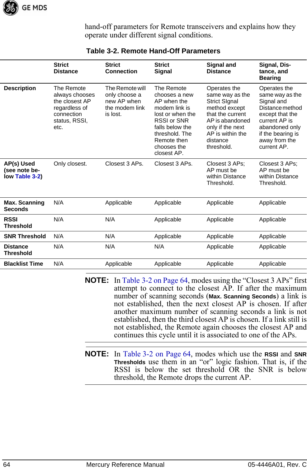
![05-4446A01, Rev. C Mercury Reference Manual 63using Offset 0. The hand-off configured Remote, using its AP Locations file, may connect to AP1, AP2, or AP3. The Remote does this by determining the Offset for each AP, then configur-ing its radio.•Current AP—Shows the name of the AP that the Remote is trying to associate with.•Advanced Control—Provides access to frequency setup parame-ters.•TDD Sync Mode—Indicates if the Access Point’s transmissions should synchronize with the GPS timing. Configure this param-eter to GPS Required when the AP is configured for Static Hopping. TDD Sync Mode (Time-Division Duplex) is useful in eliminat-ing same-network interference for multiple-AP installations. When enabled, all AP transmissions are synchronized using GPS timing information. The result is that no AP transmits while another is receiving, which prevents AP-to-AP interfer-ence. Changing this parameter requires a radio reboot.[Free Run, GPS Required; Free Run] Note: Do not use the Prefer GPS setting.•Channel Selection—Opens a submenu where you can specify channel usage.•Single Frequency Channel—The RF frequency that the integrated radio will operate on when in single frequency (non-hopping) mode. [0 to 6 for 3.5-MHz, 0 to 13 for 1.75-MHz; 0].•Frame Duration—Defines the over-the-air media access control framing. [5, 8, 10, or 20 msec; 20 msec]•Hardware Filter—This field provides a read-only indication of the maximum bandwidth of the radio. [1.75 MHz or 3.5 MHz]Hand-Off Mode Parameters In a mobile or portable application, a Remote radio needs to move and associate with different APs depending on its location. The process by which the Remote ends the connection with one AP and begins a con-nection with another AP is called “hand-off.” Table 3-2 lists the AP 1 Pattern A Offset 0 AP 2 Pattern A Offset 1 AP 3 Pattern A Offset 2 RM Static Hopping Offset 0 RM Hopping w/ Hand-offs](https://usermanual.wiki/GE-MDS/DS-MERCURY3650.User-manual/User-Guide-987144-Page-71.png)
![05-4446A01, Rev. C Mercury Reference Manual 65Advanced Configuration Menu Invisible place holderFigure 3-31. Advanced Configuration Menu•Adaptive Modulation—Enables automatic selection of modulation and FEC rate based on SNR. [enabled, disabled; enabled]•Protection Margin—A number of decibels of SNR added to the minimum SNR required for a given modulation and FEC rate. See “Modulation Protection and Hysteresis Margins” on Page 66 for more information. [0-50; 3]•Hysteresis Margin—A number of decibels of SNR added to the maximum SNR required before shifting to the next higher mod-ulation and FEC rate. See “Modulation Protection and Hyster-esis Margins” on Page 66 for more information. [0-50; 3]•Data Compression—This setting determines whether over-the-air data packets will be compressed. [enabled, disabled; enabled]•Max Modulation—Sets the highest modulation speed the trans-ceiver will use.[BPSK, QPSK-1/2, QPSK-3/4, 16QAM-1/2, 16QAM-3/4, 64QAM-2/3, 64QAM-3/4; QAM16-3/4]•Cyclic Prefix—Amount of additional information added to the over-the-air packets to mitigate the effects of channel multipath. [1/4, 1/8, 1/16,1/32; 1/16]•Channel Type—This parameter, available on Access Point units, must be set appropriately according to the signal conditions of a network. For installations with strong signals, low interference, and minimal fading, set the Channel Type parameter to Static. This setting is generally appropriate for Access Points whose Remotes are in fixed locations. It supports a large offered pay-load with high packet rates. For installations with significant interference and fading or nomadic/mobile Remotes, set the Channel Type parameter to Dynamic. [Static, Dynamic; Static]](https://usermanual.wiki/GE-MDS/DS-MERCURY3650.User-manual/User-Guide-987144-Page-73.png)
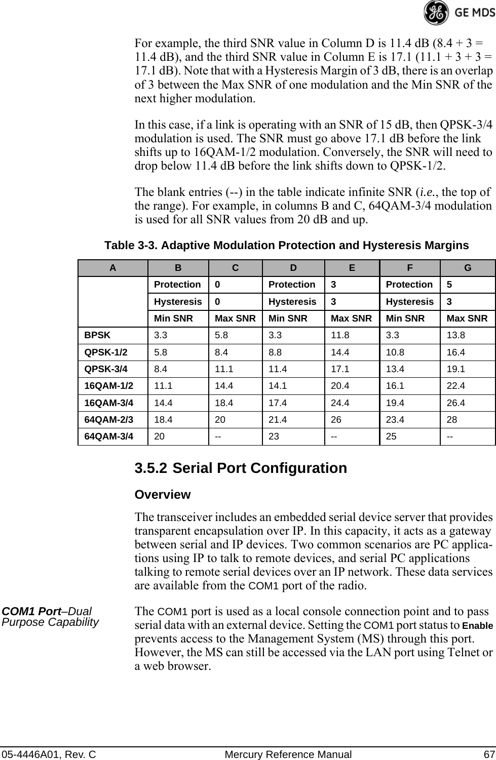
![66 Mercury Reference Manual 05-4446A01, Rev. C•ARQ—Enables the Automatic Repeat Request function. [enable, disable; enabled]•ARQ Window Size—The maximum number of blocks to send before receiving an acknowledgement. [1–1024; 512]•ARQ Block Size—ARQ is applied to payload data in blocks of this size. [4–2040; 256]•ARQ Block Lifetime—ARQ blocks are valid for this length of time. [0–655; 655]•ARQ Transmitter Delay—The length of time the transmitter waits before repeating an unacknowledged packet.[1–655; 35]•ARQ Receiver Delay—The length of time the receiver waits before repeating an unacknowledged packet. [1–655; 35]•Downlink Percentage—The percentage of link time given to downstream traffic. It should be set to 50% when Adaptive Split is set to enabled. [10-90%; 50%]•Adaptive Split—The adaptive split feature provides improved link utilitization and throughput for burst payload traffic. The Mercury is a TDD system and normally allocates 50% of its capacity to the downlink and 50% to the uplink. When adaptive split is enabled, the Media Access Controller (MAC) in the Access Point monitors the traffic flow continuously in the downlink and uplink directions. The MAC auotmatically modi-fies the downlink split in response to the traffic load. When more traffic is flowing upstream, the downlink split changes to allocate additional capacity to the uplink. When more traffic is flowing downstream, the downlink gets additional capacity. If TDD synchronization is used to synchronize Access Points and minimize inter-Access Point interference, Adaptive Split should be disabled. [enabled, disabled; enabled]Modulation Protection and Hysteresis MarginsTable 3-3 on Page 67 shows the relationship between the radio’s Protec-tion Margin, Hysteresis Margin, and the SNR range allowed for each form of modulation.Column A lists the available modulation types for the radio, while col-umns B and C show the minimum SNR range required to operate in each modulation. For example, an SNR of 5.8 dB in Column B is required for QPSK modulation with an FEC rate of 1/2. An SNR of 8.4 dB is required for QPSK modulation with an FEC rate of 3/4.Columns B and C have a Hysteresis Margin of 0 dB. This means there is no overlap between the maximum SNR for BPSK (5.8 dB) and the minimum SNR for QPSK-1/2 (5.8 dB).Columns D and E show the SNR ranges with a Protection Margin and Hysteresis Margin of 3 dB. The Protection Margin is added to each value in Columns B and C to get the corresponding value in Columns D and E. The Hysteresis Margin is then added to the Max SNR value.](https://usermanual.wiki/GE-MDS/DS-MERCURY3650.User-manual/User-Guide-987144-Page-74.png)
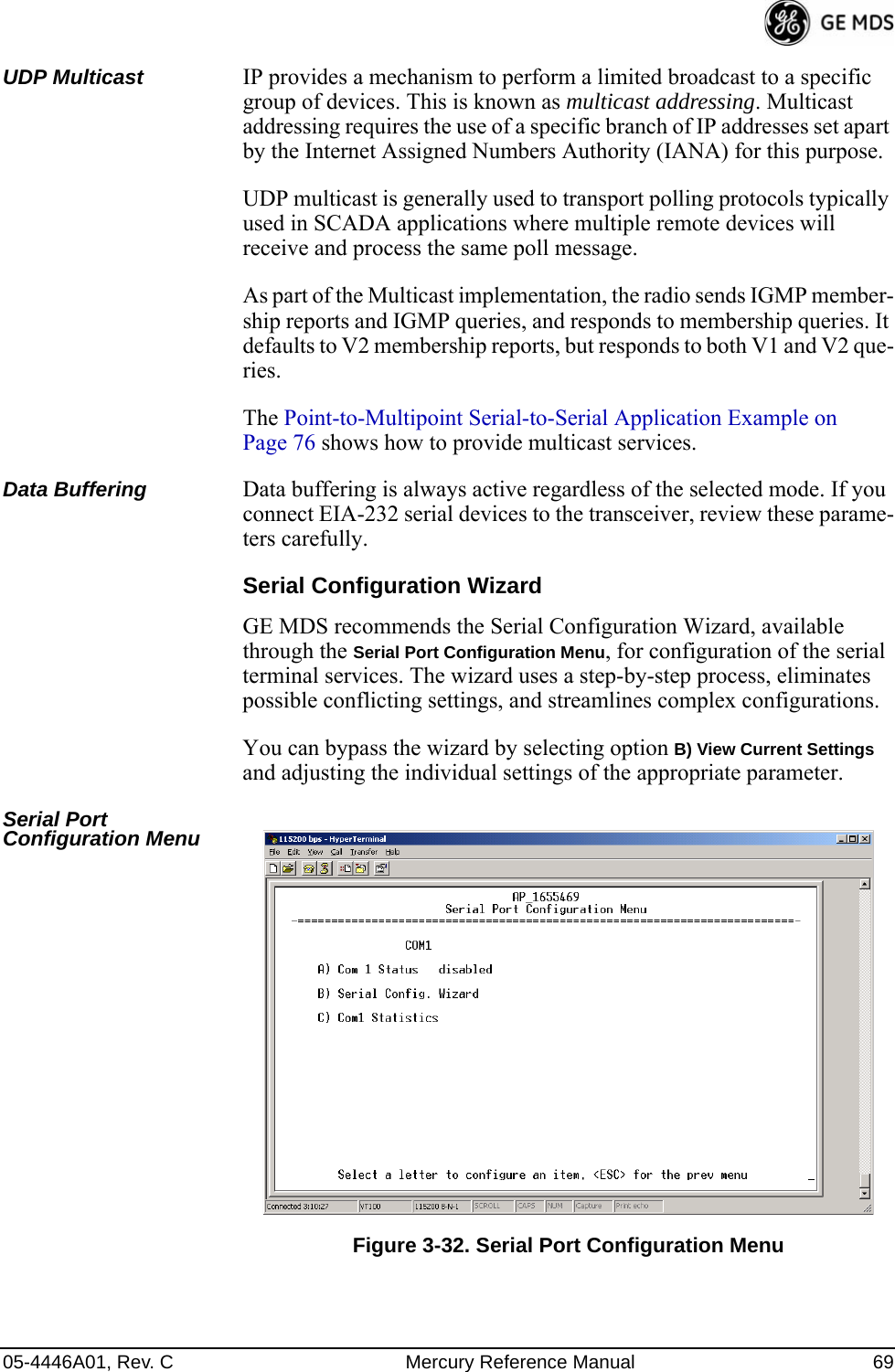
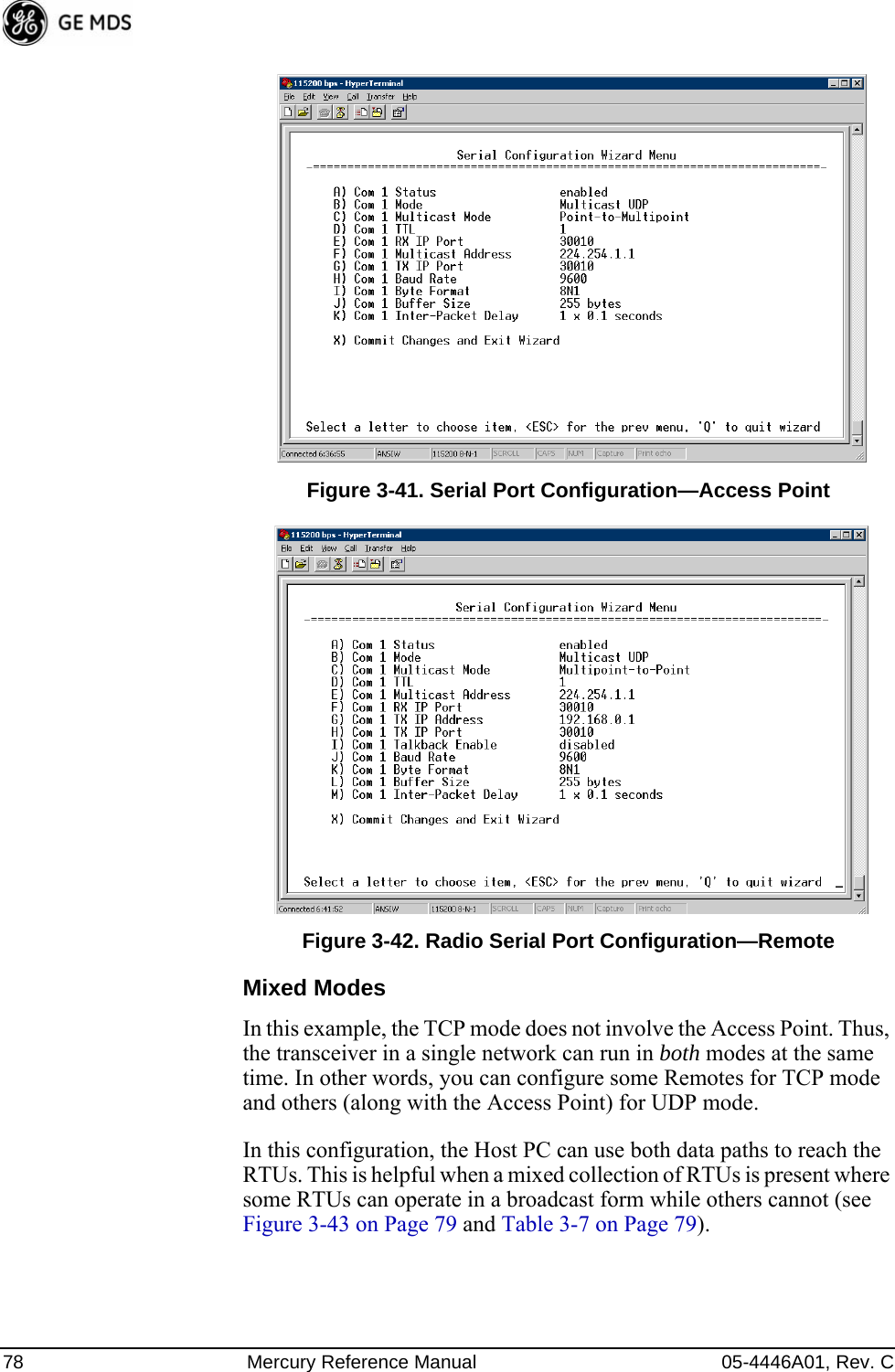
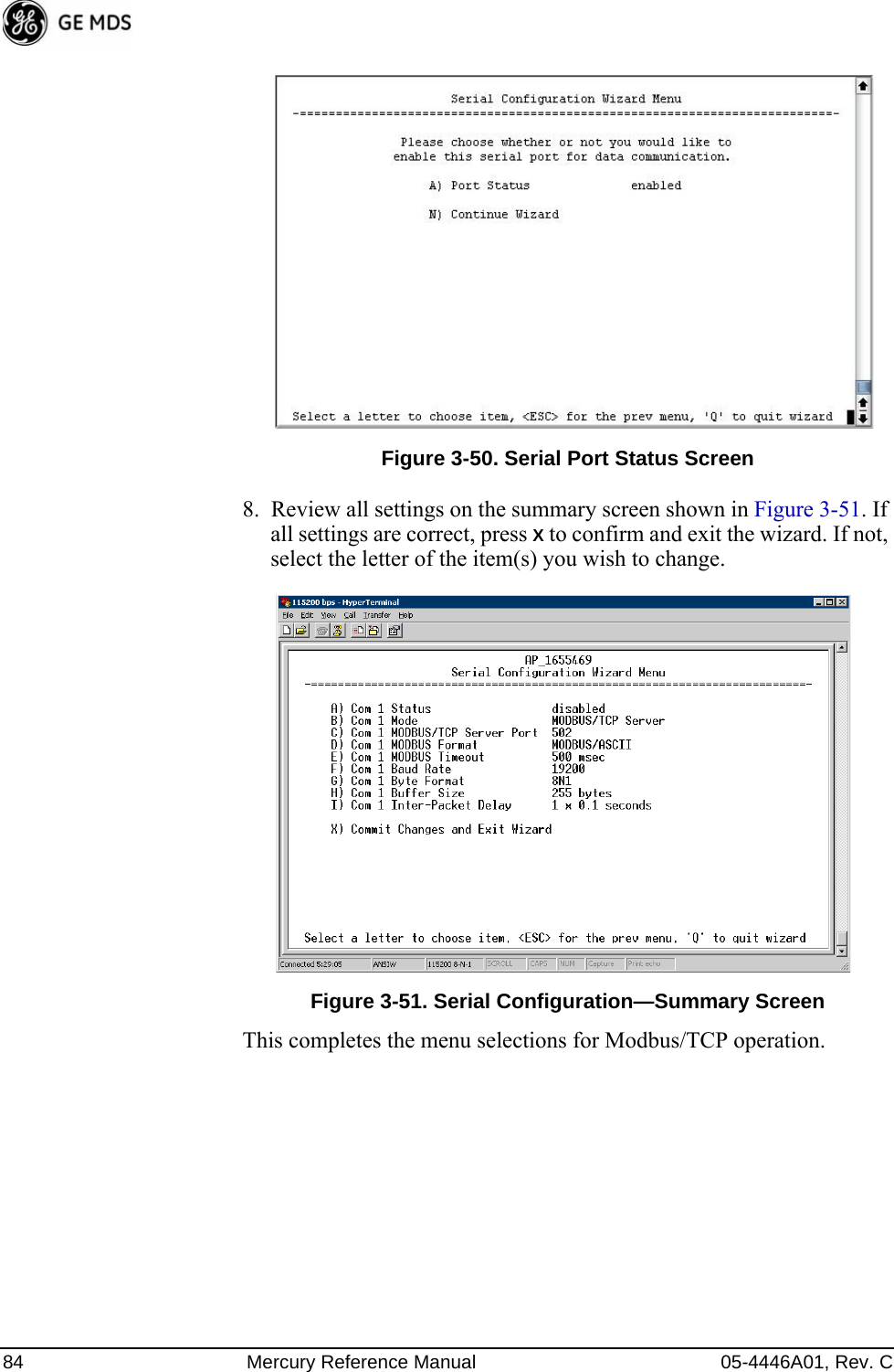
![70 Mercury Reference Manual 05-4446A01, Rev. CFigure 3-33. Serial Configuration Wizard•Begin Wizard—Tool for configuring serial ports using a step-by-step process.•View Current Settings—Displays all setable options. Varies depending on the selected IP protocol.Configuring for UDP Point-to-Multipoint Invisible place holderFigure 3-34. UDP Point-to-Multipoint MenuUse UDP point-to-multipoint to send a copy of the same packet to mul-tiple destinations, such as in a polling protocol.•Status—Enable/Disable the serial data port.•Mode—The type of IP port offered by the transceiver’s serial device server. [TCP, UDP; TCP]](https://usermanual.wiki/GE-MDS/DS-MERCURY3650.User-manual/User-Guide-987144-Page-78.png)
![05-4446A01, Rev. C Mercury Reference Manual 71•RX IP Port—Receive IP data from this source and pass it through to the connected serial device. The port number must be used by the application connecting to local TCP or UDP socket. [Any valid IP port; 30010]•TX IP Address (used instead of Local IP Address when using UDP Point-to-Multipoint)— Configure with a valid Multi-cast address (224.0.0.0–239.255.255.255). IP packets received with a matching destination address are processed by this unit. [Any legal IP address; 0.0.0.0]•TX IP Port (used instead of Local IP Port when using UDP Point-to-Multipoint)—This port number must match the number used by the application connecting to local TCP or UDP socket. [1-64,000; 30010]•Talkback Enable—Talkback is a mode where the radio returns a serial message received within a time-out period back to the last address of an incoming UDP message. If the time-out expires, the unit sends the serial data to the configured address. [Enable, Disable; Disabled]•Baud Rate—Data rate (payload) for the COM port, in bits-per-second. [1,200–115,200; 19200] •Byte Format—Formatting of data bytes, representing data bits, parity and stop bits. [7N1, 7E1, 7O1, 8N1, 8E1, 8O1, 8N1, 7N2, 7E2, 7O2, 8N2, 8E2, 8O2; 8N1]•Buffer Size—Maximum amount of characters that the Remote end buffers locally before transmitting data through the serial port. [1–255; 255]•Inter-Packet Delay—Amount of time that signal the end of a message, measured in tenths of a second. [default = 1 (that is, 1/10th of a second)]•Commit Changes and Exit Wizard—Save and execute changes made on this screen (shown only after changes have been entered).](https://usermanual.wiki/GE-MDS/DS-MERCURY3650.User-manual/User-Guide-987144-Page-79.png)
![72 Mercury Reference Manual 05-4446A01, Rev. CInvisible place holderFigure 3-35. UDP Point-to-Point MenuConfiguring for UDP Point-to-Point Use UDP point-to-point configuration to send information to a single device.•Status—Enable/Disable the serial data port. •IP Protocol—UDP Point-to-Point. This is the type of IP port offered by the transceiver’s serial device server. [TCP, UDP; TCP]•Remote IP Address—Data received through the serial port is sent to this IP address. To reach multiple Remotes in the net-work, use UDP Point-to-Multipoint. [Any legal IP address; 0.0.0.0]•Remote IP Port—The destination IP port for data packets received through the serial port on the transceiver. [1–64,000; 30010]•Local IP Port—Port number where data is received and passed through to the serial port. The application connecting to this transceiver must use this port number.[1–64,000; 30010,]•Packet Redundancy Mode—For proper operation, all radios’ Serial Packet Redundancy mode must match (Single Packet mode vs. Packet Repeat mode). This is because a transceiver, when in Packet Repeat mode, sends 12 extra characters (sequence numbers, etc.) to control the delivery of the repeated data. Misconfigurations might result in undesired operation.•Data Baud Rate—Data rate (payload) for the COM port, in bits-per-second. [1,200–115,200; 19200] •Byte Format—Formatting of data bytes. Data bits, parity and stop bits. [7N1, 7E1, 7O1, 8N1, 8E1, 8O1, 8N1, 7N2, 7E2, 7O2, 8N2, 8E2, 8O2; 8N1]](https://usermanual.wiki/GE-MDS/DS-MERCURY3650.User-manual/User-Guide-987144-Page-80.png)
![05-4446A01, Rev. C Mercury Reference Manual 73•Commit Changes and Exit Wizard—Save and execute changes made on this screen (shown only after changes have been entered).Configuring for TCP Mode Invisible place holderFigure 3-36. TCP Client Menu (Remote)•Status—Enable/Disable the serial data port. •IP Protocol—TCP Client. This is the type of IP port offered by the transceiver’s serial device server. [TCP, UDP; TCP]•Primary Host Address—The IP address to be used as a destina-tion for data received through the serial port.[Any legal IP address; 0.0.0.0]•Primary IP Port—The destination IP port for data packets received through the serial port on the transceiver.[Any valid IP port; 30010]•Secondary Host Address—The IP address to be used as a desti-nation for data received through the serial port, in case the primary host address is not available.[Any legal IP address; 0.0.0.0]•Secondary IP Port—The destination IP port for data packets received through the serial port on the transceiver, used along with the secondary host address above.[Any valid IP port; COM1: 30010]•Outgoing Connection’s Inactivity Timeout—Amount of time (in seconds) that the transceiver waits for data before terminat-ing the TCP session. [0–600; 600]•Data Baud Rate—Data rate (payload) for the COM port, in bits-per-second. [1,200–115,200; 19200] •Byte Format—Interface signaling parameters. Data bits, parity and stop bits. [7N1, 7E1, 7O1, 8N1, 8E1, 8O1, 8N1, 7N2, 7E2, 7O2, 8N2, 8E2, 8O2; 8N1]](https://usermanual.wiki/GE-MDS/DS-MERCURY3650.User-manual/User-Guide-987144-Page-81.png)
![74 Mercury Reference Manual 05-4446A01, Rev. C•Buffer Size—Maximum amount of characters that the Remote end buffers locally before transmitting data through the serial port. [1–255; 255]•Inter-Frame Packet Delay—A measurement representing the end of a message, measured in tenths of a second.[default = 1 (that is, 1/10th of a second)]•Commit Changes and Exit Wizard—Save and execute changes made on this screen (shown only after changes have been entered). Invisible place holderFigure 3-37. TCP Server Menu (AP)•Status—Enable/Disable the serial data port.•IP Protocol—TCP Server. This is the type of IP port offered by the transceiver’s serial device server. [TCP, UDP; TCP]•Local Listening IP Port—Receive IP data from this source and pass it through to the connected serial device. The applica-tion connecting to the local TCP or UDP socket must use this port number.[Any valid IP port; 30010]•Baud Rate—Data rate (payload) for the COM port, in bits-per-second. [1,200–115,200; 19200] •Byte Format—Interface signaling parameters. Data bits, parity and stop bits. [7N1, 7E1, 7O1, 8N1, 8E1, 8O1, 8N1, 7N2, 7E2, 7O2, 8N2, 8E2, 8O2; 8N1]•Buffer Size—Maximum amount of characters that the Remote end buffers locally before transmitting data through the serial port. [1–255; 255]•Inter-Packet Delay—Amount of time that signal the end of a message, measured in tenths of a second. [default = 1 (that is, 1/10th of a second)]](https://usermanual.wiki/GE-MDS/DS-MERCURY3650.User-manual/User-Guide-987144-Page-82.png)
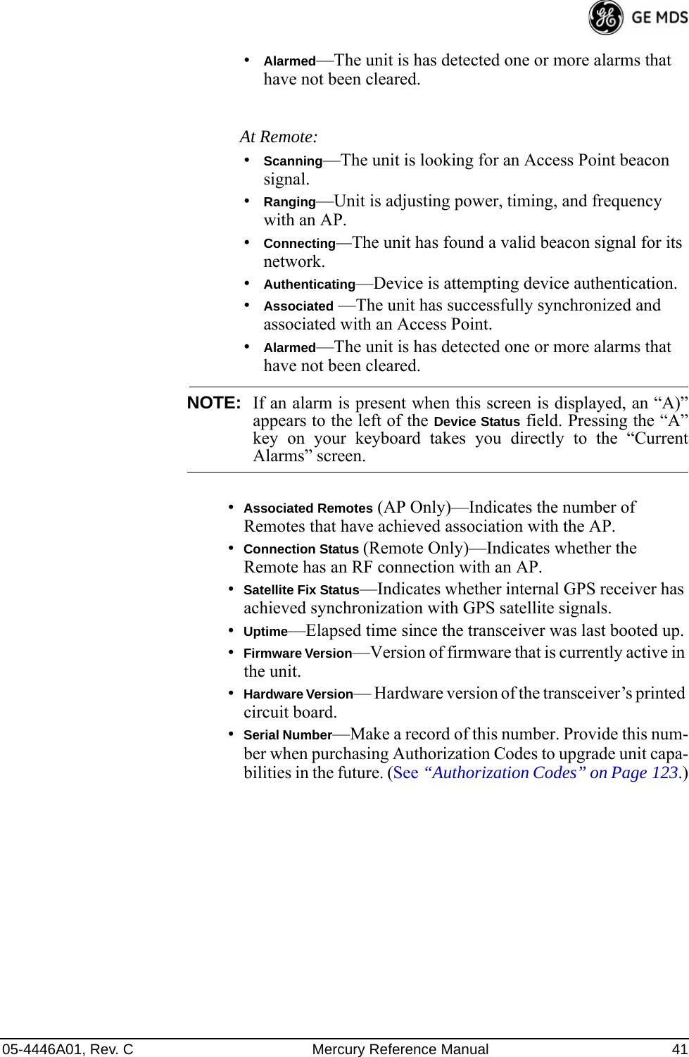
![86 Mercury Reference Manual 05-4446A01, Rev. C3.7.1 Device Security MenuThe Device Security Menu (Figure 3-53) controls how the radios can be accessed either locally or remotely for configuration and management.Invisible place holderFigure 3-53. Device Security Menu•Telnet Access—Controls Telnet access to the transceiver’s man-agement system. [enabled, disabled; enabled]•SSH Access—Controls access to the Secure Shell (SSH) server.[enabled, disabled; enabled]•HTTP Mode—Controls access to the transceiver’s management system via the web server. [disabled, HTTP, HTTPS; HTTP]•HTTP Auth Mode—Selects the mode used for authenticating a web user. [Basic Auth, MD5 Digest; Basic Auth]•User Auth Method—View/set the method of authentication for users. [Local, Radius; Local]•User Auth Fallback—View/set method of authentication to use if the RADIUS server is unavailable. [None, Local; None] •User Passwords—Allows changing of Administrative and Guest passwords. When selected, a new screen appears (Figure 3-54 on Page 87).](https://usermanual.wiki/GE-MDS/DS-MERCURY3650.User-manual/User-Guide-987144-Page-94.png)
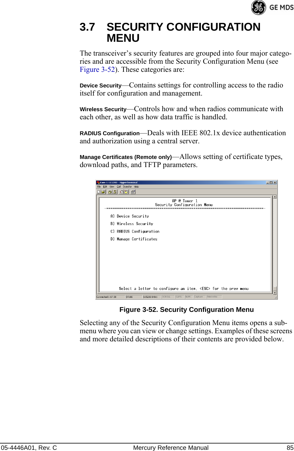
![05-4446A01, Rev. C Mercury Reference Manual 87User Passwords Menu Invisible place holderFigure 3-54. User Passwords MenuTo change the Administrator or Guest password, select the appropriate menu item (A or B). A flashing cursor appears to the right. From here, type the new password, which can be any alpha-numeric string up to 13 characters long. The change is asserted when you press the Return key.•Change Admin Password—Allows you to set a new password. [any alpha-numeric string up to 13 characters; admin]•Change Guest Password—Allows you to set a new password. [any alpha-numeric string up to 13 characters; guest]TIP: For enhanced security, consider using misspelled words, a combi-nation of letters and numbers, and a combination of upper and lower case letters. Also, the more characters used (up to 13), the more secure the password. These strategies help protect against sophisticated hackers who use a database of common words (for example, dictionary attacks) to determine a password.3.7.2 Wireless Security MenuThe features in the Wireless Security menu (Figure 3-55 on Page 88) control the communication of data across the wireless link. You can authenticate the radios locally via a list of authorized radios, or remotely via a centralized IEEE 802.1x device authentication server. This server provides a centralized authentication mechanism based on standards.](https://usermanual.wiki/GE-MDS/DS-MERCURY3650.User-manual/User-Guide-987144-Page-95.png)
![88 Mercury Reference Manual 05-4446A01, Rev. CInvisible place holderFigure 3-55. Wireless Security Menu•Device Auth Mode—View/set the device’s authentication method. [None, Local, IEEE 802.1X; None]•Data Encryption—Controls the over-the-air payload data’s AES-128 bit encryption. [enable, disable; disabled]•Encryption Phrase—View/set the phrase used to generate encryp-tion keys when encrypting over-the-air payload. [any alpha-numeric string of 8 to 15 characters; <empty>]•Max Remotes (AP only)—The maximum number of remotes an AP can associate with.•Approved Remotes (AP only)—Launches a submenu where you can view, add, or delete approved Remotes. (See Figure 3-56.)Approved Remotes Submenu Setting the Device Auth Mode to Local forces an AP to check the Approved Remotes List before establishing a radio link. A Remote must be in the list before the AP associates and grants authorization. Before enabling this option, at least one entry must already exist in the View Approved Remotes list.](https://usermanual.wiki/GE-MDS/DS-MERCURY3650.User-manual/User-Guide-987144-Page-96.png)
![05-4446A01, Rev. C Mercury Reference Manual 89Invisible place holderFigure 3-56. Approved Remotes Submenu•Add Remote—Enter the MAC address of Remote.[Any valid 6-digit hexadecimal MAC address; 00:00:00:00:00:00] •Delete Remote—Enter the MAC address of Remote. For security purposes, you should delete a stolen or deprovisioned radio from this list.•Add Associated Remotes—Add all currently associated remotes to the approved remote list. Alternatively, you can enter each Remote MAC manually.•Delete All Remotes—Remove (complete purge) all Remotes from current list.•View Approved Remotes—Listing of approved Remotes by MAC address. These radios are authorized to join this AP. If a Remote is not in this list, it cannot associate with this AP.3.7.3 IEEE 802.1x Device AuthenticationThis section covers the configuration needed for the radios to access the IEEE 802.1x device authentication server, which provides Device Level Security and for Wireless Access Security. GE MDS does not provide the server software.Operation of Device AuthenticationDevice authentication forces the radio to authenticate before allowing user traffic to traverse the wireless network. When Device Security is configured to use IEEE 802.1x as the Authentication Method, Remote radios need three types of certificates: public (client), private, and root (Certificate Authority). These files are unique to each Remote radio and must first be created at the server and then installed into each unit via TFTP. The certificate files must be in DER format.Device authentication uses the serial number of each radio as the Common Name (CN) in its certificate and in its RADIUS identity field.](https://usermanual.wiki/GE-MDS/DS-MERCURY3650.User-manual/User-Guide-987144-Page-97.png)
![05-4446A01, Rev. C Mercury Reference Manual 91RADIUS Configuration Menu Invisible place holderFigure 3-57. Radius Configuration Menu•Auth Server Address—The IP address of the authentication server. [any valid IP address; 0.0.0.0]•Auth Server Port—The UDP Port of the authentication server. [1812, 1645, 1812]•Auth Server Shared Secret—User authentication and Device authentication require a common shared secret to complete an authentication transaction. This entry must match the string used to configure the appropriate files on the authentication server. [<empty>; any alpha-numeric string up to 16 characters]•User Auth Mode—RADIUS Authentication algorithm.[PAP, CHAP, EAP; PAP]NOTE: CHAP is more secure than PAP. PAP may display the loginpassword in log files at the authentication server while CHAPwill encrypt the login password.3.7.4 Manage CertificatesUse Certificate generation software to generate certificate files, then install these files into each Remote unit using TFTP. This is done using the Manage Certificates Menu (Figure 3-58 on Page 92). The certificate files must be in DER format. The Common Name (CN) field in the public certificate file must match the serial number of the unit it is installed on.](https://usermanual.wiki/GE-MDS/DS-MERCURY3650.User-manual/User-Guide-987144-Page-99.png)
![92 Mercury Reference Manual 05-4446A01, Rev. CInvisible place holderFigure 3-58. Manage Certificates Menu•TFTP Host Address—(Telnet/Terminal only)—IP address of the com-puter on which the TFTP server resides. This same IP address is used in other screens/functions (reprogramming, logging, etc.). Changing it here also changes it for other screens/functions.[Any valid IP address; 127.0.0.1].•Transfer Options—A menu for configuring the TFTP transfer. (See Figure 3-59 on Page 93.)Three certificate files (Root CA, Client, and Private Key) must be present in each of the Remote radios. Use the commands described below to install these files into each Remote radio:•Certificate Type—Selects one of the three certificate file types mentioned above. [Root CA, Client, Private Key; Root CA]•Certificate Filename—Specifies the software path and filename for downloading certificates.•Retrieve Certificate—Initiates the retrieval of the certificate file from the storage location. A successful installation issues a Com-plete status message.NOTE: It is imperative that the three certificate files are installedcorrectly into the Remote radio, in their respective file types.If they are not, the Remote is un-authenticated for data traffic.Consult your network administrator for more information.](https://usermanual.wiki/GE-MDS/DS-MERCURY3650.User-manual/User-Guide-987144-Page-100.png)
![94 Mercury Reference Manual 05-4446A01, Rev. CInvisible place holderFigure 3-60. Redundancy Configuration Menu (AP Only)•Redundancy Configuration—Enable/disable redundancy switcho-ver for AP. [enabled, disabled; disabled]•Network Event Triggers—This selection opens a submenu (Figure 3-61 on Page 95) where you can set/view the trigger sta-tus for Network Events.•Radio Event Triggers—This selection opens a submenu (Figure 3-62 on Page 95) where you can set/view the trigger sta-tus for Radio Events, such as a loss of associated Remotes or excessive packet errors.•Hardware Event Triggers—This selection opens a submenu (Figure 3-63 on Page 96) where you can set/view the trigger sta-tus for initialization/hardware errors.•Redundancy Configuration Options—This selection opens a sub-menu (Figure 3-64 on Page 96) where you can set the threshold criteria for declaring an error event.•Force Switchover—Selecting this option forces a manual (user initiated) switchover to the backup AP. The “challenge ques-tion” Are you sure? (y/n) is presented to avoid an unintended switchover. To invoke the change, press the letter y followed by the Enter key.](https://usermanual.wiki/GE-MDS/DS-MERCURY3650.User-manual/User-Guide-987144-Page-102.png)
![05-4446A01, Rev. C Mercury Reference Manual 95Network Event Triggers Menu Invisible place holderFigure 3-61. Network Events Triggers Menu•Network Interface Error—This setting determines whether or not a network interface error will cause redundancy switchover. [enabled, disabled; disabled]Radio Event Triggers Invisible place holderFigure 3-62. Radio Event Triggers•Lack of associated remotes exceeded threshold—This setting deter-mines whether or not a switchover occurs when a lack of asso-ciated Remote units exceeds the time period set in Figure 3-65 on Page 97. [enabled, disabled; disabled]•Packet Receive Errors exceeded threshold—This setting determines whether or not a switchover occurs when the number of Packet Receive errors exceeds the number set in Figure 3-66 on Page 97. [enabled, disabled; disabled]](https://usermanual.wiki/GE-MDS/DS-MERCURY3650.User-manual/User-Guide-987144-Page-103.png)
![96 Mercury Reference Manual 05-4446A01, Rev. CHardware Event Triggers Invisible place holderFigure 3-63. Hardware Event Triggers•Init/Hardware Error—This setting determines whether or not an initialization or hardware error results in a redundancy switcho-ver. [enabled, disabled; disabled]Redundancy Configuration Options MenuUse this menu (Figure 3-64) to set the thresholds for the Lack of Asso-ciated Remotes and Packet Receive Errors. Selecting either item opens a submenu where you can view or change settings.Invisible place holderFigure 3-64. Redundancy Configuration Options Menu•Lack of Associated Remotes Exceeded Threshold—This selection opens a submenu (Figure 3-65) where you can view or change the time period allowed for a lack of associated Remotes.](https://usermanual.wiki/GE-MDS/DS-MERCURY3650.User-manual/User-Guide-987144-Page-104.png)
![05-4446A01, Rev. C Mercury Reference Manual 97•Packet Receive Errors Exceeded Threshold—This selection opens a submenu (Figure 3-66 on Page 97) where you can view or change the maximum allowable number of receive errors.Lack of Associated Remotes Exceeded Threshold Menu Invisible place holderFigure 3-65. Lack of Associated Remotes Exceeded Threshold Menu•Lack of Remotes for—Select this item to change the time setting (in seconds) for a lack of associated Remotes. When there are no associated Remotes for a period exceeding this time, a redun-dancy switchover occurs. [60-500; 500]Packet Receive Errors Exceeded Threshold Menu Invisible place holderFigure 3-66. Packet Receive Errors Exceeded Threshold Menu](https://usermanual.wiki/GE-MDS/DS-MERCURY3650.User-manual/User-Guide-987144-Page-105.png)
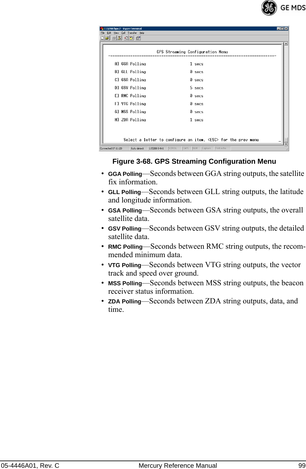
![98 Mercury Reference Manual 05-4446A01, Rev. C•Maximum Receive Errors—Select this item to change the maxi-mum allowable number of receive errors. When the number of errors exceeds this number, a redundancy switchover occurs. [0-1000; 500]3.9 GPS CONFIGURATION (REMOTE ONLY)This menu allows you to view or set important parameters for the built-in Global Positioning System (GPS) receiver in the Mercury Remote.Invisible place holderFigure 3-67. GPS Configuration Menu (Remote Only)•Stream GPS to Console—Used to enable/disable streaming of GPS NMEA data to the console port (COM1). Baud rate is 4800 baud when Stream GPS to console is enabled.[enabled, disabled; disabled]•GPS to Console Baud Rate—The serial baud rate when GPS streaming is enabled.•Send GPS via UDP—Used to enable/disable sending GPS NMEA data to a server via UDP. [enabled, disabled; disabled]•GPS UDP Server IP Address—Specify the destination address for GPS NMEA UDP packets. [any valid IP address; 0.0.0.0]•GPS UDP Server UDP Port—Destination UDP port for GPS NMEA UDP packets. [valid UDP port number; 0]•GPS Streaming Configuration—A submenu for setting GPS NMEA outputs. (See Figure 3-68 on Page 99.)](https://usermanual.wiki/GE-MDS/DS-MERCURY3650.User-manual/User-Guide-987144-Page-106.png)
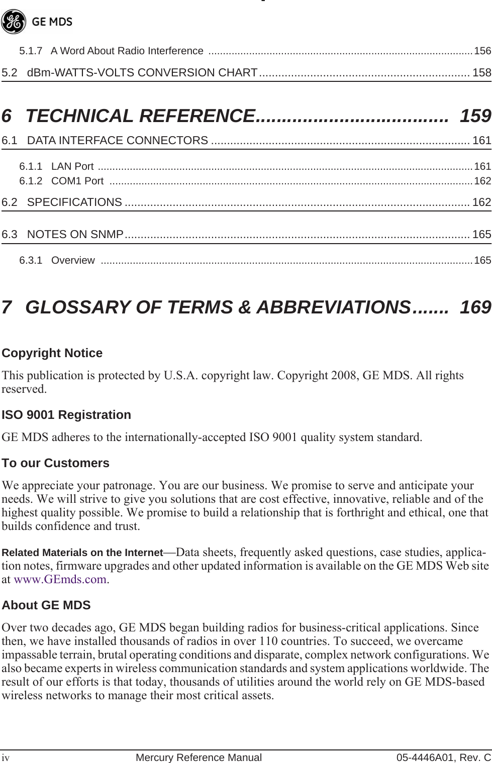
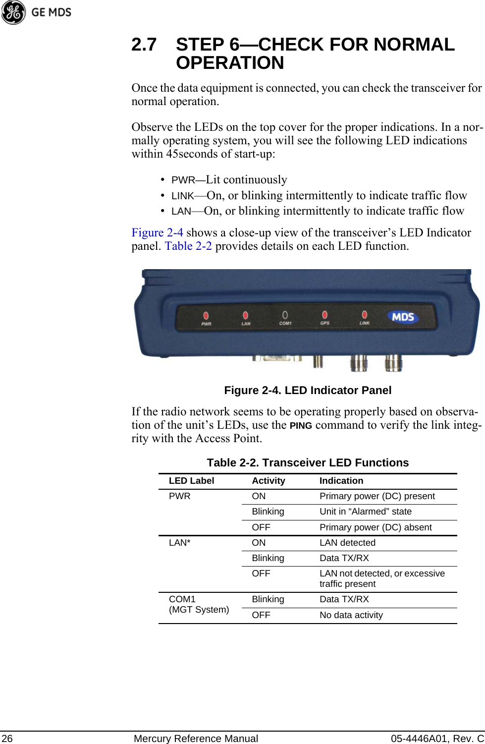
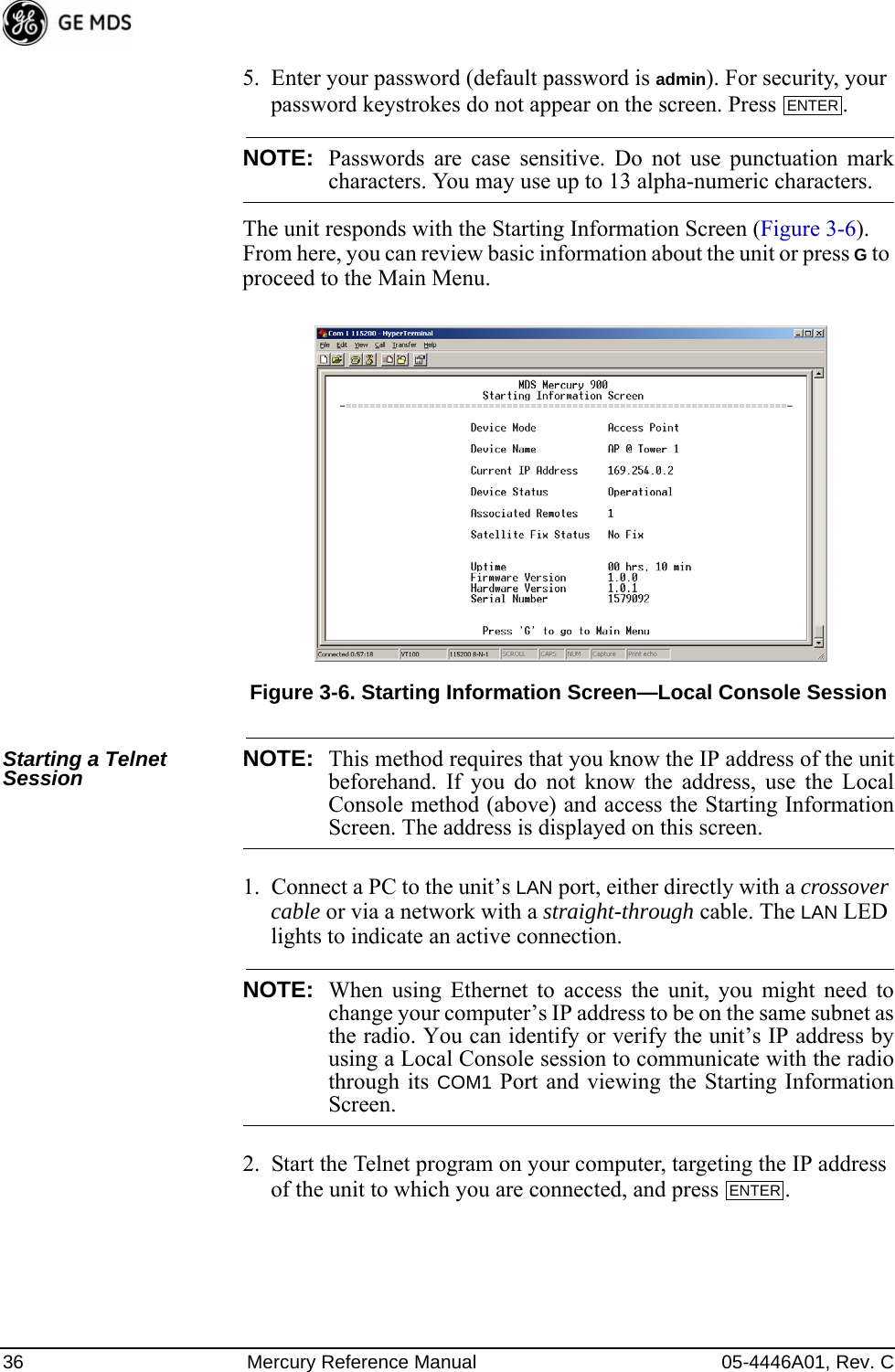
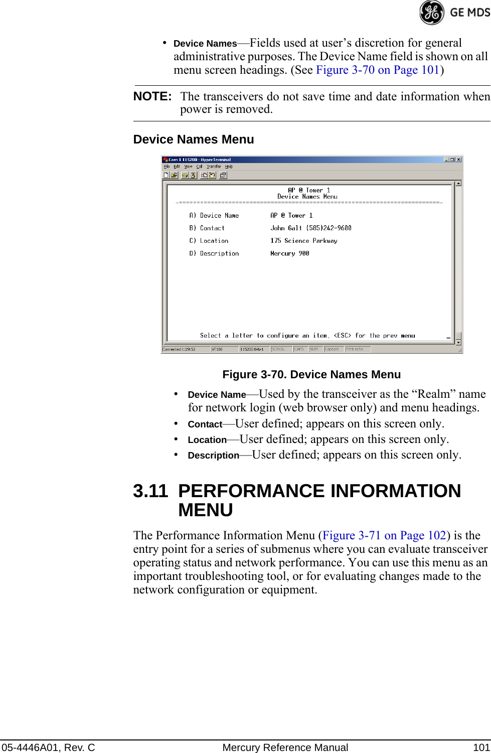
![100 Mercury Reference Manual 05-4446A01, Rev. C3.10 DEVICE INFORMATION MENUFigure 3-69 shows the menu that displays basic administrative data on the unit to which you are connected. It also provides access to user-spe-cific parameters such as date/time settings and device names.Figure 3-69. Device Information Menu•Model (Display only)•Serial Number (Display only)•Uptime (Display only)—Elapsed time since boot-up.•Date—Current date being used for the transceiver logs. User-set-able. (Value lost with power failure if SNTP [Simple Network Time Protocol] server not accessible.) •Time—Current time of day. User-setable. Setting: HH:MM:SS (Value lost with power failure if SNTP server not accessible.)•Date Format—Select presentation format:• Generic = dd Mmm yyyy• European = dd-mm-yyyy• US = mm-dd-yyyy•Console Baud Rate—Used to set/display data communications rate (in bits-per-second) between a connected console terminal and the radio. [115200]•UTC Time Offset—Set/view the number of hours difference between your local clock time and Universal Coordinated Time. Offsets for U.S. times zones are shown in the chart below.Time Zone (U.S.) UTC Offset (Hours)PST -8MST -7CST -6EST -5](https://usermanual.wiki/GE-MDS/DS-MERCURY3650.User-manual/User-Guide-987144-Page-108.png)
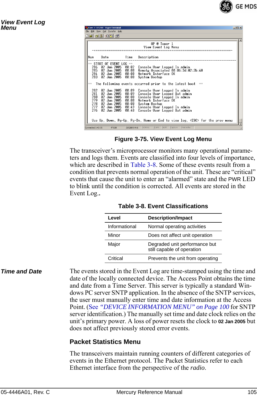
![104 Mercury Reference Manual 05-4446A01, Rev. CEvent Log Menu Invisible place holderFigure 3-74. Event Log Menu•Current Alarms—Shows active alarms (if any) reported by the transceiver.•View Event Log—Displays a log of radio events arranged by event number, date, and time. (Example shown in Figure 3-75 on Page 105).•Clear Event Log—Erases all previously logged events.•Send Event Log—Sends the event log to the server. You must answer the challenge question Send File? y/n before the request proceeds.•Event Log Host Address—Set/display the IP address of the TFTP server. [any valid IP address; 0.0.0.0]•Event Log Filename—Set/display the name of the event log file on the TFTP server. [any valid filename; eventlog.txt]•Transfer Options—A menu for configuring the TFTP transfer.•Syslog Server Address—Use this selection to set or view the IP address of the Syslog server. Syslog is a standardized protocol for sending IP log data across a network. Low cost (or even free) Syslog downloads are available online by searching for the term “Syslog Server.” [any valid IP address; 0.0.0.0]](https://usermanual.wiki/GE-MDS/DS-MERCURY3650.User-manual/User-Guide-987144-Page-112.png)
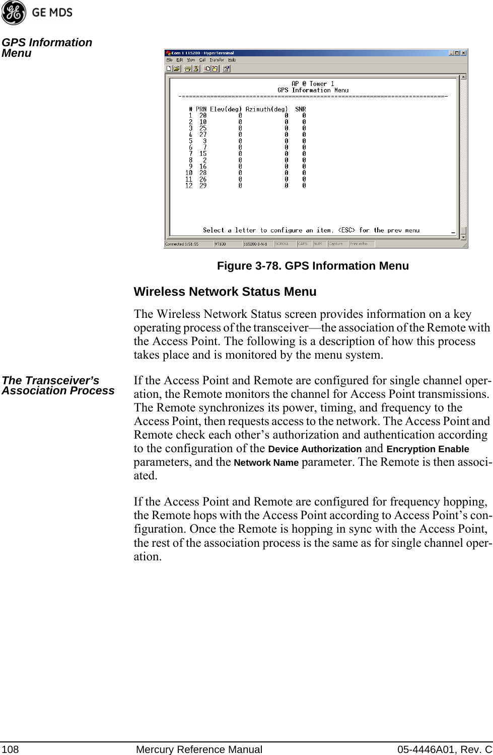
![05-4446A01, Rev. C Mercury Reference Manual 107GPS Status Menu Invisible place holderFigure 3-77. GPS Status Menu•GPS Serial Number—The serial number of the GPS unit in the radio.•GPS Firmware Version—The firmware version running on the GPS chip.•Satellite Fix Status—Indicates whether or not the unit has achieved signal lock with the minimum required number of GPS satellites. The transceiver requires a fix on five satellites to achieve Precise Positioning Service (PPS) and four to maintain PPS. [No Fix, Fix]•Number of Satellites—Shows the number of GPS satellites received by the transceiver. Although there are typically 24 active GPS satellites orbiting the Earth twice a day, only a sub-set of these is “visible” to a receiver at a given location. A good signal provides information from six to ten satellites.•Latitude—Shows the transceiver’s latitudinal location (in degrees), based on GPS data received from the satellites.•Longitude—Shows the transceiver’s longitudinal location (in degrees), based on GPS data received from the satellites.•Altitude—Shows the transceiver’s altitude above sea level (in feet), based on GPS data received from the satellites.•GPS Information—Shows data about the individual satellites being received, including the Pseudo-Random Noise (PRN) code (a unique bit stream for each satellite), the satellite’s ele-vation (in degrees), azimuth (in degrees), and the sig-nal-to-noise ratio of the carrier signal (SNR). Figure 3-78 on Page 108 shows a layout example for this screen.](https://usermanual.wiki/GE-MDS/DS-MERCURY3650.User-manual/User-Guide-987144-Page-115.png)
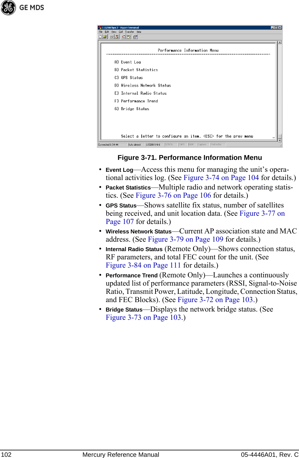
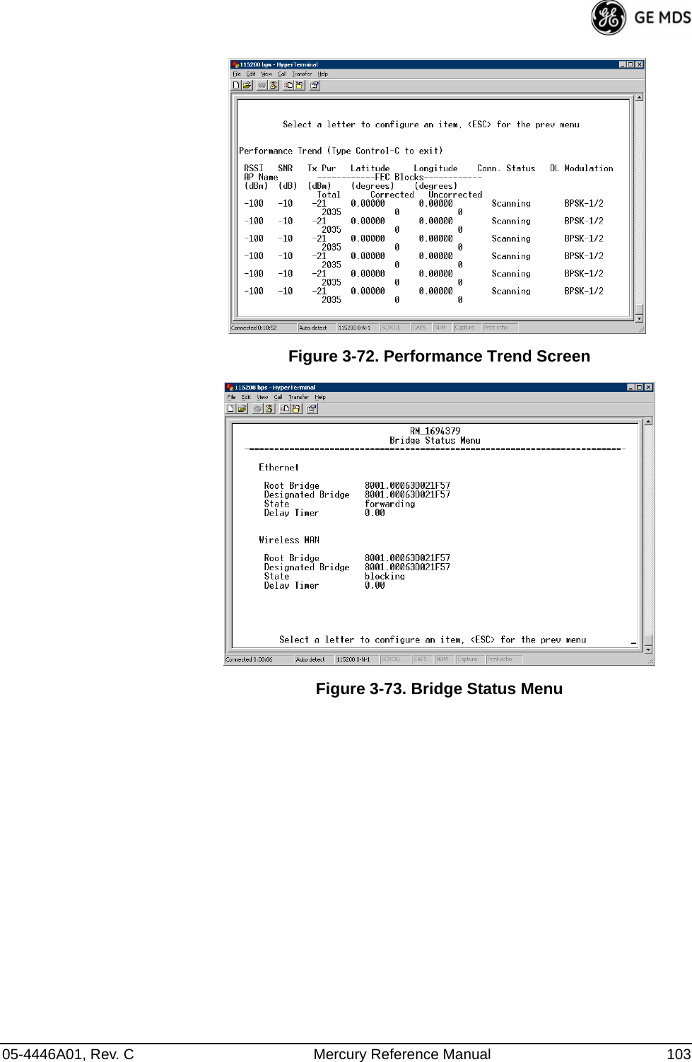
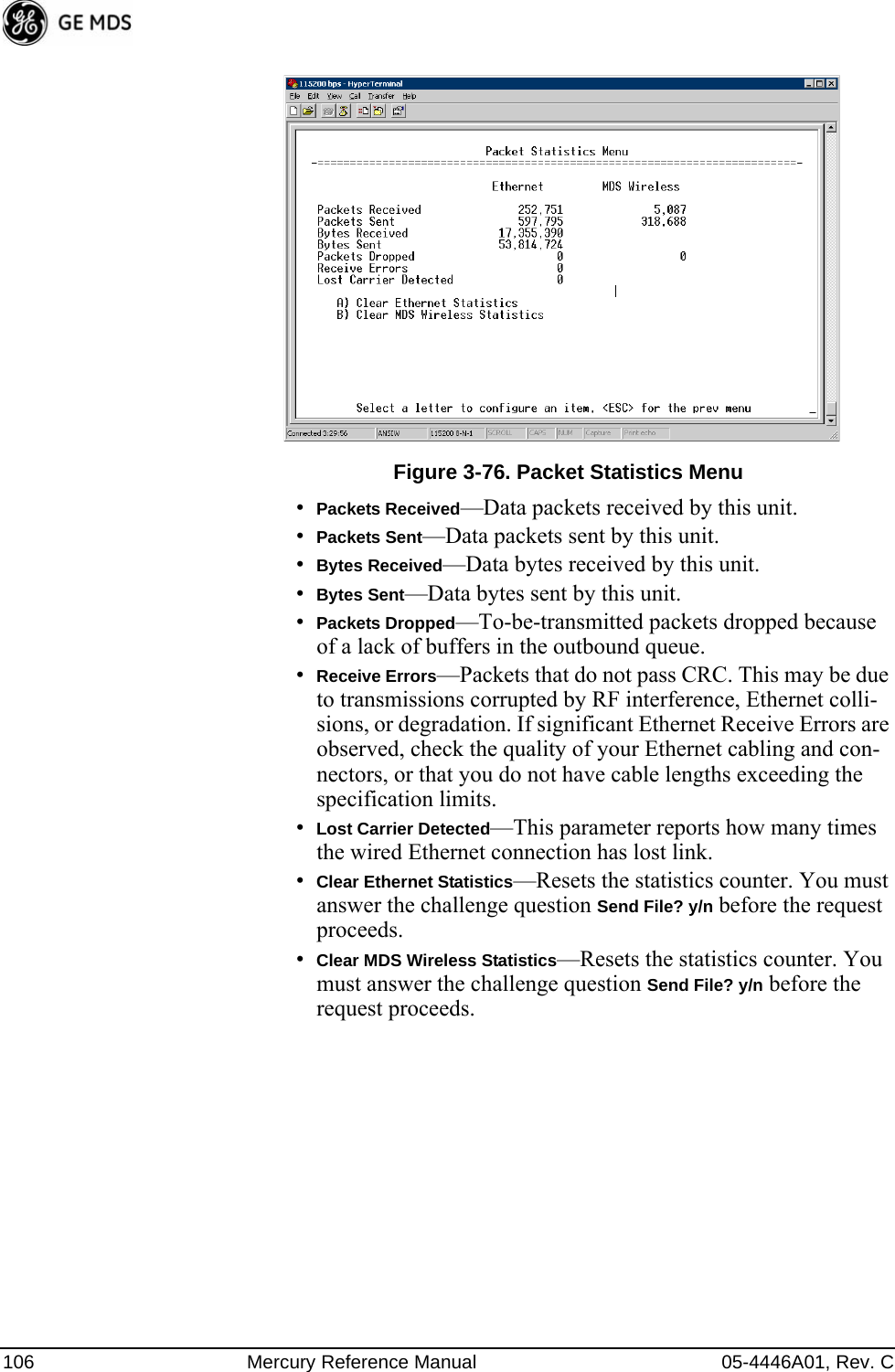
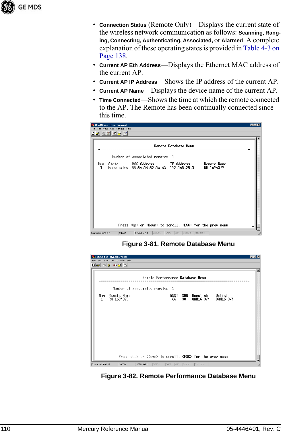
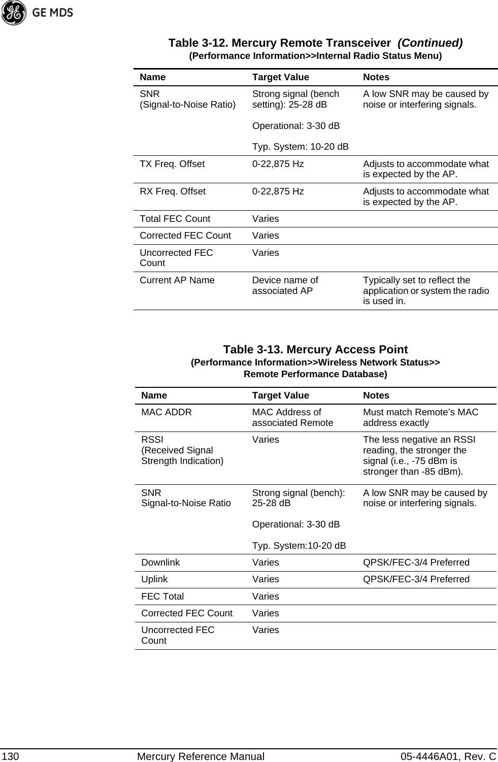
![05-4446A01, Rev. C Mercury Reference Manual 109Invisible place holderFigure 3-79. Wireless Network Status Menu (AP)Invisible place holderFigure 3-80. Wireless Network Status Menu (Remote)•Device Status—Displays the overall operating condition of the transceiver. [Operational, Alarmed]•Associated Remotes (AP Only)—Shows the number of Remote transceivers currently associated with the AP.•PA Temperature—Shows the power amplifier temperature in degrees Celsius.•Remote Database (AP Only)—Displays a submenu where associ-ated Remotes are listed in table form according to their number, operational state, MAC address, IP address, and name (if assigned). (See Figure 3-81 on Page 110.)•Remote Performance Database (AP Only)—Displays a submenu where associated Remote performance data is listed in table form. Remotes are presented according to their number, MAC address, RSSI, SNR, modulation type, uplink modulation, and FEC total. (See Figure 3-82 on Page 110.)](https://usermanual.wiki/GE-MDS/DS-MERCURY3650.User-manual/User-Guide-987144-Page-117.png)
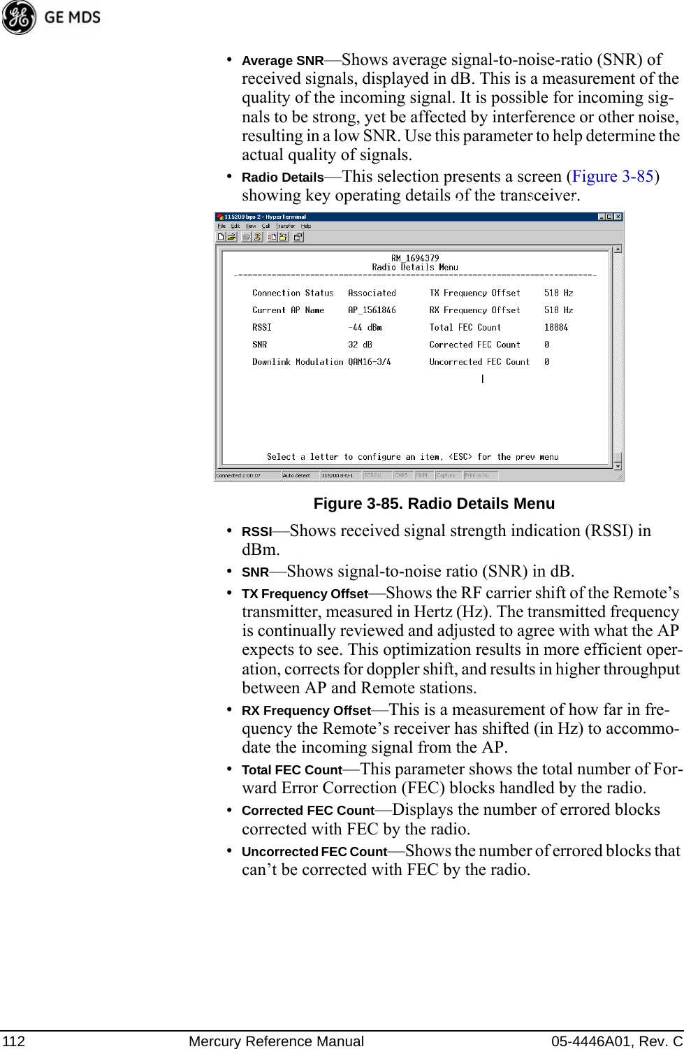
![05-4446A01, Rev. C Mercury Reference Manual 111Invisible place holderFigure 3-83. Remote Database Details Menu (AP)Internal Radio Status Menu (Remote Only)Invisible place holderFigure 3-84. Internal Radio Status (Remote Only)•Connection Status—Indicates whether or not the Remote station has associated with an AP. [Associated, Scanning, Ranging, Con-necting, Authorizing]•Current AP Name—Shows the Device Name of the current AP.•Transmit Power—Shows the RF power output from the transmit-ter. The AP changes the transmit power of the Remote to match the desired receive power at the APs receiver. This provides end-to-end power control.•Average RSSI—Shows average received signal strength indica-tion (RSSI) of incoming RF signals, displayed in dBm.](https://usermanual.wiki/GE-MDS/DS-MERCURY3650.User-manual/User-Guide-987144-Page-119.png)
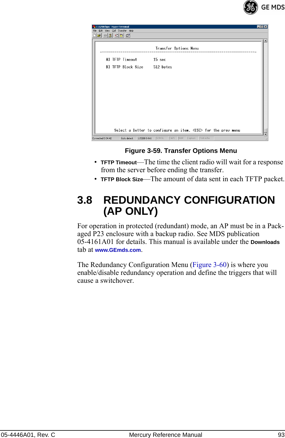
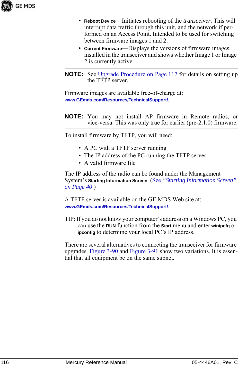
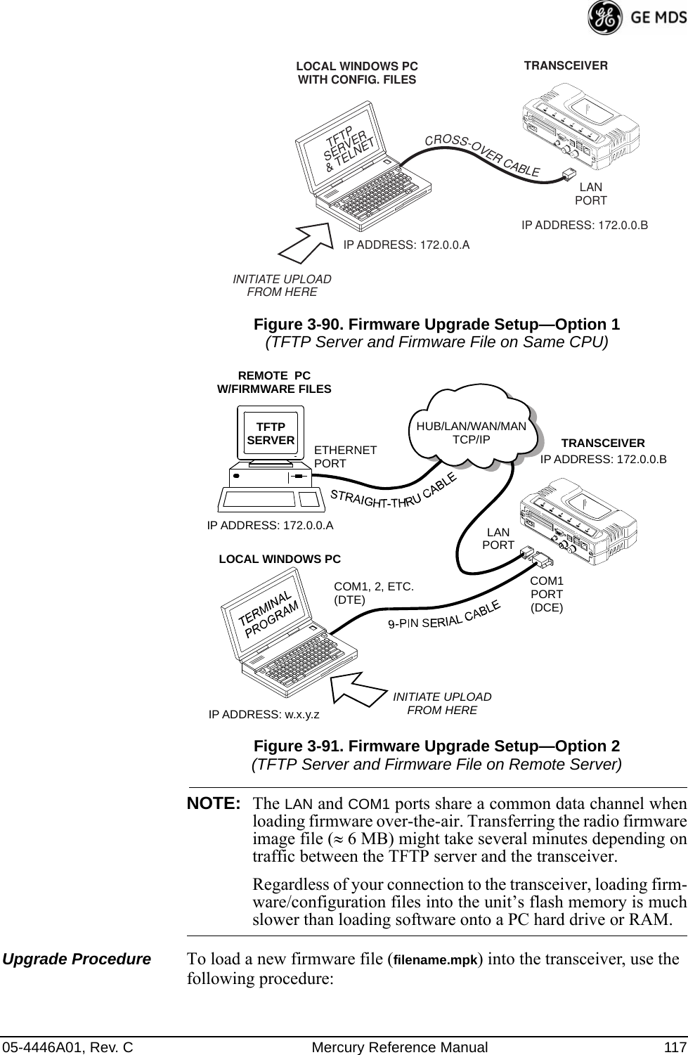
![05-4446A01, Rev. C Mercury Reference Manual 115NOTE: Always read the release notes for downloaded firmware. Thesenotes contain important information on compatibility and anyspecial steps needed for proper installation.All units and versions have two resident images. Version 1.4.4 had two .mpk files, one for the Access Point and one for the Remote. As of ver-sion 2.1.0, there is only one .mpk file which you can use with both Access Points and Remotes.The transceiver has two copies of the firmware (microprocessor code) used for the operating system and applications. One copy is “active” and the second is standing by, ready to be used once activated. You can load new firmware into the inactive position and place it in service whenever you desire.Invisible place holderFigure 3-89. Reprogramming Menu•TFTP Host Address—IP address of the host computer from which to get the file. [Any valid IP address] This same IP address is used in other screens/functions (reprogramming, logging, etc.). Changing it here also changes it for other screens/functions.•Firmware Filename—Name of file to be received by the TFTP server. [Any 40-character alphanumeric string] Verify that this cor-responds to the TFTP directory location. May require sub-direc-tory, for example: me-bkrc-2_1_0.mpk.•Transfer Options—A menu for configuring the TFTP transfer.•Retrieve File—Initiates the file transfer from the TFTP server. The new file is placed into inactive firmware image. [Y, N]•Image Verify—Initiate the verification of the integrity of firmware file held in unit.•Image Copy—Initiate the copying of the active firmware into the inactive image.](https://usermanual.wiki/GE-MDS/DS-MERCURY3650.User-manual/User-Guide-987144-Page-123.png)
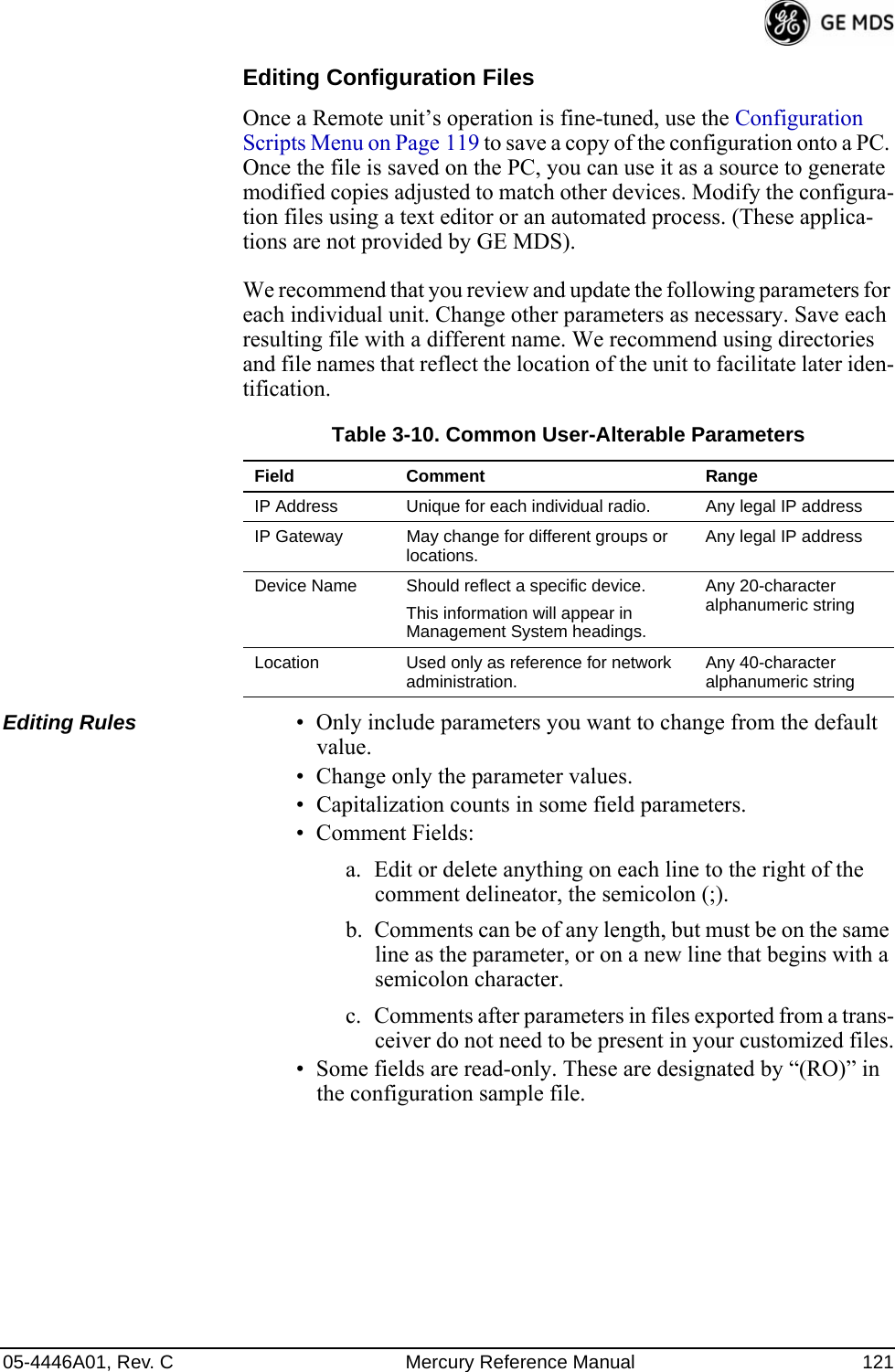
![120 Mercury Reference Manual 05-4446A01, Rev. CInvisible place holderFigure 3-92. Configuration Scripts Menu•TFTP Host Address—IP address of the computer on which the TFTP server resides. [Any valid IP address]•Config Filename—Name of file containing this unit’s configura-tion profile that will be transferred to the TFTP server. The con-figuration information is in plain-text ASCII format.[Any 40-character alphanumeric string] May require a sub-direc-tory, for example: config\mercury-config.txt. (See “Configuration Scripts Menu” on Page 119 for more information.)NOTE: The filename field is used to identify the desired incoming fileand as the name of the file exported to the TFTP server. Beforeexporting a unit’s configuration, name it in a way that reflectsthe radio’s services or other identification.•Transfer Options—A menu for configuring the TFTP transfer.•Category—The category of parameters to send or receive.•Retrieve File—Initiate the file transfer of the configuration file from TFTP server into the transceiver.•Send File—Initiate the file transfer from the transceiver’s current configuration file to TFTP server.NOTE: See “Upgrade Procedure” on Page 117 for details on settingup the TFTP server.Sample of Configuration Script FileA sample configuration script file is provided as part of every firmware release. Firmware images and sample files are available free-of-charge at: www.GEmds.com/Resources/TechnicalSupport/.The name of the specific file includes the firmware revision number, represented by the “x” characters in the following example: mercury-config-x_x_x.txt.](https://usermanual.wiki/GE-MDS/DS-MERCURY3650.User-manual/User-Guide-987144-Page-128.png)
![122 Mercury Reference Manual 05-4446A01, Rev. CPing Utility Menu Invisible place holderFigure 3-93. Ping Utility Menu•Address to Ping—Address to send a Ping. [Any valid IP address]•Count—Number of Ping packets to be sent.•Packet Size—Size of each Ping data packet (bytes).•Ping—Send Ping packets to address shown on screen.This screen is replaced with a detailed report of Ping activity (see example in Figure 3-94). Press any key after viewing the results to return to this menu.Invisible place holderFigure 3-94. Ping Results Screen](https://usermanual.wiki/GE-MDS/DS-MERCURY3650.User-manual/User-Guide-987144-Page-130.png)
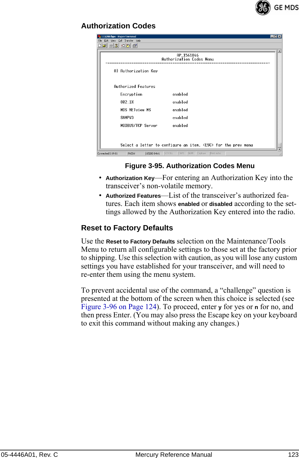
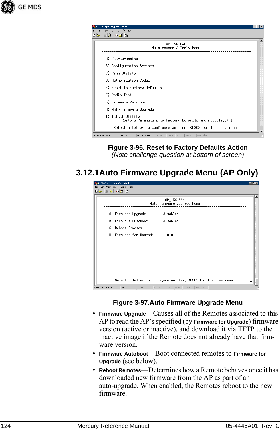
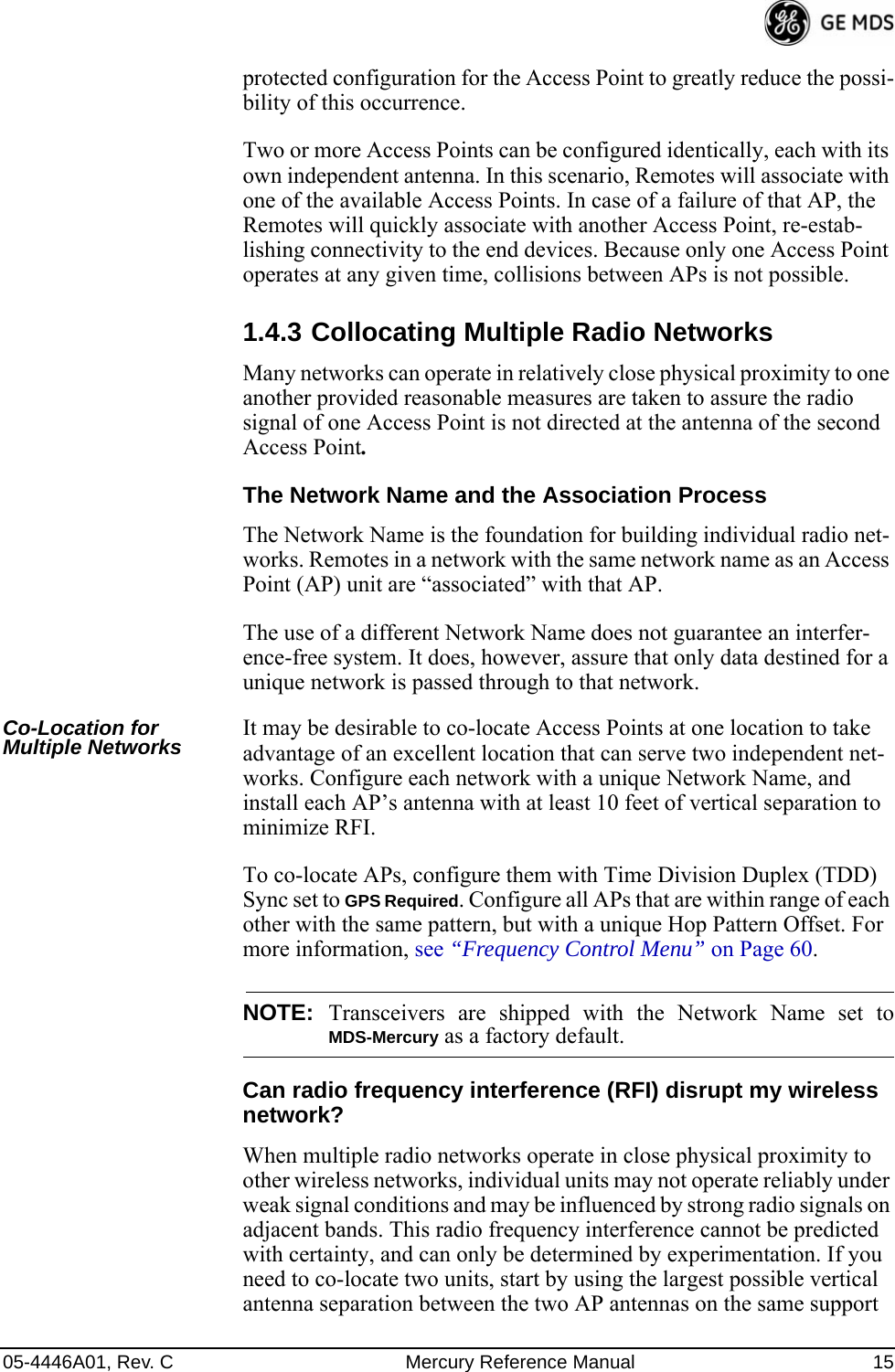
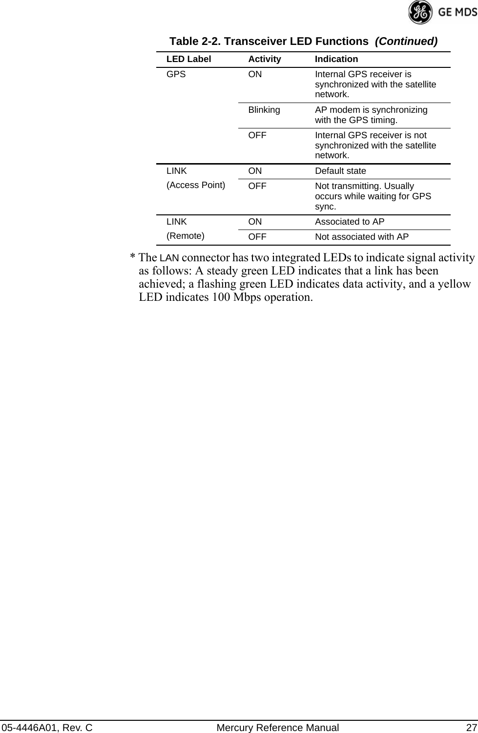
![05-4446A01, Rev. C Mercury Reference Manual 125NOTE: To use the Auto Upgrade/Reboot feature, both the AP andRemotes must already be running version 2.1.0 or newer firm-ware.•Firmware for Upgrade—Specifies the firmware version that the Remotes should download, if they do not already have it.Radio Test MenuUsing this menu, you can manually key the radio transmitter for perfor-mance checks and set several parameters that will be used when the Radio Mode is set to Test.Invisible place holderFigure 3-98. Radio Test MenuNOTE : Using Test Mode disrupts traffic through the radio. If the unitis an Access Point, it will disrupt traffic through the entirenetwork. The Test Mode function is automatically limited to10 minutes. Only use Test Mode for brief measurements.•Radio Mode—Sets/displays the radio’s operating mode. To change the setting, press A on the PC’s keyboard and press the Spacebar to toggle between the two settings. Press the Enter key to select the desired state. [Normal, Test; Normal]•Test Status—This read-only parameter shows the current state of the radio. [Radio is Operational, Reconfiguring the Radio, Ready to KEY]The following parameters are read-only unless A) Radio Mode is first selected and set to Test. In Test Mode, these items become selectable, and you can set their entries using the Spacebar or with a numeric entry, followed by pressing the Enter key.•Test Key—Sets/displays keying status of the radio’s transmitter. Use the Spacebar to view selections. [disabled, enabled; disabled]](https://usermanual.wiki/GE-MDS/DS-MERCURY3650.User-manual/User-Guide-987144-Page-133.png)
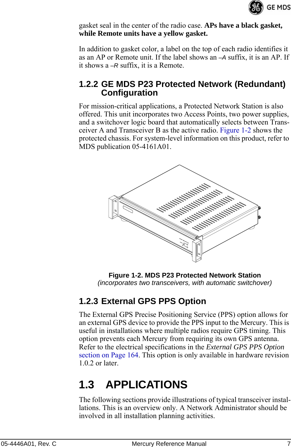
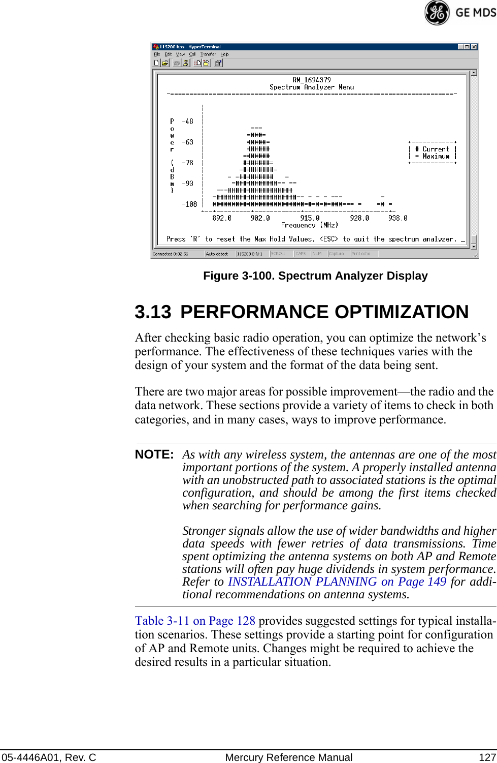
![126 Mercury Reference Manual 05-4446A01, Rev. C•Test Transmit Power—Sets/displays the transmitter’s power set-ting. Make a numerical entry within the allowable range. [-30 to +30 dBm]•Test Channel—Sets/displays the radio’s test channel number. Make a numerical entry within the allowable range.[0-13; 0]•Test RF Bandwidth—Sets/displays the transmitter’s bandwidth for testing. Use the Spacebar to view selections.[1.75. 3.5 MHz; 1.75 MHz]•Test Burst Percentage—Sets/displays the percentage of Burst size to use for testing. Make a numerical entry within the allowable range. [0-100%; 100]Spectrum Analyzer Menu (Remote Only)Using this menu, you can enable or disable the remote’s spectrum ana-lyzer mode (Figure 3-99 on Page 126). When enabled, the remote dis-plays through the terminal a spectrum analyzer view of its transmit power and frequency (Figure 3-100 on Page 127).Figure 3-99. Spectrum Analyzer Menu](https://usermanual.wiki/GE-MDS/DS-MERCURY3650.User-manual/User-Guide-987144-Page-134.png)
![05-4446A01, Rev. C Mercury Reference Manual 131Additional Considerations for Mobile OperationConsider the following key points for all mobile installations:• Use connectionware—The use of connectionware in the mobile lap-tops is highly recommended for better operation of a mobile data system. GE MDS provides connectionware from one of the vendors in this market. Contact your factory representative for details.• Plan your network coverage—Deploy Access Points so that they provide overlapping coverage with each other. Access Points must use the same Network Name to enable roaming service.• Set the RSSI Threshold to -85 dBm—This level is typically used for mobile systems with good performance. Make sure there is overlap-ping coverage of more than one AP to provide continuous coverage.• At every AP Radio, review the following settings when providing service to mobile remotes:•TDD Sync—Set to GPS Required.•Pattern Offset—Each AP should be different. Cell planning is required if there are overlaps.•Hop Pattern—Set the same on all APs.•Compression [disabled]—Disable radio compression. Data com-pression is best performed by the connectionware running on the mobile laptop PC. Gains in efficiency are made because connectionware compresses data at a higher stack level, and it aggregates multiple data frames and streams into a single packet. Compression at the radio level, although highly effi-cient, works only at the individual packet level.](https://usermanual.wiki/GE-MDS/DS-MERCURY3650.User-manual/User-Guide-987144-Page-139.png)