GE MDS DS-MERCURY3651 WIRELESS IP/ETHERNET TRANSCEIVER User Manual
GE MDS LLC WIRELESS IP/ETHERNET TRANSCEIVER
GE MDS >
4446E Mercury Series Ref Man
Reference Manual
05-4446A01, Rev. E
MARCH 2009
Wireless IP/Ethernet Transceiver
Covering all AP and Remote Units
including Mercury 900, 3650, and Option Set 1 Remotes
MDS MercuryTM Series

05-4446A01, Rev. E Mercury Reference Manual i
TABLE OF CONTENTS
1 PRODUCT OVERVIEW & APPLICATIONS ............ 1
1.1 ABOUT THIS MANUAL................................................................................................... 3
1.1.1 Start-Up Guide .................................................................................................................... 3
1.1.2 Online Access to Manuals ................................................................................................... 3
1.1.3 Conventions Used in This Manual ....................................................................................... 3
1.2 PRODUCT DESCRIPTION............................................................................................. 4
1.2.1 Model Offerings ................................................................................................................... 6
1.2.2 Remote Radio with Option Set 1 .........................................................................................7
1.2.3 GE MDS P23 Protected Network (Redundant) Configuration ............................................. 8
1.2.4 External GPS PPS Option ................................................................................................... 9
1.3 APPLICATIONS ..............................................................................................................9
1.3.1 Mobile/Fixed Data System .................................................................................................. 9
1.3.2 Wireless LAN ..................................................................................................................... 10
1.3.3 Point-to-Point LAN Extension .............................................................................................11
1.3.4 Serial Radio Network Connectivity .....................................................................................11
1.3.5 Multiple Protocols and/or Services .....................................................................................11
1.3.6 Wireless LAN with Mixed Services .................................................................................... 12
1.3.7 Upgrading Older Wireless Network with Serial Interfaces ................................................. 13
1.4 NETWORK DESIGN CONSIDERATIONS.................................................................... 14
1.4.1 Extending Network Coverage with Repeaters ................................................................... 14
1.4.2 Protected Network Operation using Multiple APs .............................................................. 16
1.4.3 Collocating Multiple Radio Networks ................................................................................. 16
1.5 GE MDS CYBER SECURITY SUITE............................................................................ 17
1.6 ACCESSORIES ............................................................................................................ 19
2 TABLETOP EVALUATION & TEST SETUP............. 21
2.1 OVERVIEW................................................................................................................... 23
2.2 STEP 1: CONNECT THE ANTENNA PORTS............................................................... 23
2.3 STEP 2: CONNECT THE PRIMARY POWER.............................................................. 24

ii Mercury Reference Manual 05-4446A01, Rev. E
2.4 STEP 3: CONNECT PC TO THE TRANSCEIVER ....................................................... 25
2.5 STEP 4: REVIEW TRANSCEIVER CONFIGURATION ................................................ 25
2.5.1 Getting Started .................................................................................................................. 25
2.5.2 Procedure .......................................................................................................................... 25
2.5.3 Basic Configuration Defaults ............................................................................................. 25
2.6 STEP 5: CONNECT LAN OR SERIAL DATA EQUIPMENT.......................................... 26
2.6.1 Option Set 1 Connectors ................................................................................................... 28
2.7 STEP 6: CHECK FOR NORMAL OPERATION ............................................................ 29
3 DEVICE MANAGEMENT......................................... 31
3.1 INTRODUCTION .......................................................................................................... 33
3.1.1 Differences in the User Interfaces .....................................................................................33
3.2 ACCESSING THE MENU SYSTEM ............................................................................. 35
3.2.1 Methods of Control ............................................................................................................ 36
3.2.2 PC Connection and Log In Procedures ............................................................................. 36
3.2.3 Navigating the Menus ........................................................................................................ 40
3.3 BASIC OVERVIEW OF OPERATION........................................................................... 42
3.3.1 Starting Information Screen ............................................................................................... 42
3.3.2 Main Menu ......................................................................................................................... 43
3.4 CONFIGURING NETWORK PARAMETERS ............................................................... 45
3.4.1 Network Configuration Menu .............................................................................................45
3.4.2 Ethernet Port Configuration Menu ..................................................................................... 56
3.4.3 Bridge Configuration .......................................................................................................... 58
3.4.4 SNMP Agent Configuration ................................................................................................ 58
3.4.5 AP Location Push Config Menu ......................................................................................... 60
3.4.6 SNTP Server Configuration ............................................................................................... 64
3.5 RADIO CONFIGURATION............................................................................................ 65
3.5.1 Radio Configuration Menu ................................................................................................. 65
3.5.2 Serial Port Configuration ................................................................................................... 76
3.6 MODBUS / TCP SERVER CONFIGURATION ............................................................. 88
3.6.1 Modbus/TCP in Mercury TransceiversAn Overview ...................................................... 88
3.6.2 Menu Selections ................................................................................................................ 89
3.7 SECURITY CONFIGURATION MENU ......................................................................... 92
3.7.1 Device Security Menu ....................................................................................................... 93

05-4446A01, Rev. E Mercury Reference Manual iii
3.7.2 Wireless Security Menu ..................................................................................................... 95
3.7.3 IEEE 802.1x Device Authentication ................................................................................... 97
3.7.4 Manage Certificates .......................................................................................................... 99
3.8 REDUNDANCY CONFIGURATION (AP ONLY) ......................................................... 102
3.9 GPS CONFIGURATION (REMOTE ONLY) ................................................................ 107
3.10 DEVICE INFORMATION MENU ............................................................................... 109
3.11 PERFORMANCE INFORMATION MENU..................................................................110
3.12 MAINTENANCE/TOOLS MENU ............................................................................... 123
3.12.1 Installing Firmware via TFTP ........................................................................................ 129
3.12.2 Auto Firmware Upgrade Menu (AP Only) ..................................................................... 138
3.13 PERFORMANCE OPTIMIZATION............................................................................ 140
3.13.1 Proper Operation and What to Look For ....................................................................... 143
4 TROUBLESHOOTING & RADIO
MEASUREMENTS.................................................. 147
4.1 TROUBLESHOOTING................................................................................................ 149
4.1.1 Interpreting the Front Panel LEDs ................................................................................... 149
4.1.2 Troubleshooting With the Embedded Management System ........................................... 150
4.1.3 Using Logged Operation Events ..................................................................................... 153
4.1.4 Alarm Conditions ............................................................................................................. 154
4.1.5 Correcting Alarm Conditions ............................................................................................ 155
4.1.6 Logged Events ................................................................................................................ 155
4.2 RADIO (RF) MEASUREMENTS ................................................................................. 157
4.2.1 Antenna System SWR and Transmitter Power Output .................................................... 157
4.2.2 Antenna Aiming (For Directional Antennas)...................................................................... 158
5 PLANNING A RADIO NETWORK ......................... 161
5.1 INSTALLATION PLANNING ....................................................................................... 163
5.1.1 General Requirements .................................................................................................... 163
5.1.2 Site Selection .................................................................................................................. 164
5.1.3 Terrain and Signal Strength ............................................................................................. 165
5.1.4 Antenna & Feedline Selection ......................................................................................... 165
5.1.5 How Much Output Power Can be Used? ........................................................................ 169
5.1.6 Conducting a Site Survey ................................................................................................ 169
5.1.7 A Word About Radio Interference .................................................................................... 170

iv Mercury Reference Manual 05-4446A01, Rev. E
5.1.8 ERP Compliance at 900 MHz .......................................................................................... 172
5.1.9 ERP Compliance at 3650 MHz ........................................................................................ 173
5.2 dBm-WATTS-VOLTS CONVERSION CHART............................................................ 174
6 TECHNICAL REFERENCE.................................... 175
6.1 DATA INTERFACE CONNECTORS ........................................................................... 177
6.1.1 LAN Port .......................................................................................................................... 177
6.1.2 COM1 Port ...................................................................................................................... 177
6.2 SPECIFICATIONS ...................................................................................................... 178
6.3 NOTES ON SNMP...................................................................................................... 180
6.3.1 Overview ......................................................................................................................... 180
7 GLOSSARY OF TERMS & ABBREVIATIONS...... 185
Copyright Notice
This publication is protected by U.S.A. copyright law. Copyright 2009, GE MDS. All rights
reserved.
ISO 9001 Registration
GE MDS adheres to the internationally-accepted ISO 9001 quality system standard.
To our Customers
We appreciate your patronage. You are our business. We promise to serve and anticipate your
needs. We will strive to give you solutions that are cost effective, innovative, reliable and of the
highest quality possible. We promise to build a relationship that is forthright and ethical, one that
builds confidence and trust.
Related Materials on the Internet
—
Data sheets, frequently asked questions, case studies, applica-
tion notes, firmware upgrades and other updated information is available on the GE MDS Web site
at www.GEmds.com.
About GE MDS
Over two decades ago, GE MDS began building radios for business-critical applications. Since
then, we have installed thousands of radios in over 110 countries. To succeed, we overcame
impassable terrain, brutal operating conditions and disparate, complex network configurations. We
also became experts in wireless communication standards and system applications worldwide. The
result of our efforts is that today, thousands of utilities around the world rely on GE MDS-based
wireless networks to manage their most critical assets.

05-4446A01, Rev. E Mercury Reference Manual v
The majority of GE MDS radios deployed since 1985 are still installed and performing within our
customers' wireless networks. That’s because we design and manufacture our products in-house,
according to ISO 9001 which allows us to control and meet stringent global quality standards.
Thanks to our durable products and comprehensive solutions, GE MDS is the wireless leader in
industrial automation
—
including oil and gas production and transportation, water/wastewater
treatment, supply and transportation, electric transmission and distribution and many other utility
applications. GE MDS is also at the forefront of wireless communications for private and public
infrastructure and online transaction processing. Now is an exciting time for GE MDS and our cus-
tomers as we look forward to further demonstrating our abilities in new and emerging markets.
As your wireless needs change you can continue to expect more from GE MDS. We'll always put
the performance of your network above all. Visit us at www.GEmds.com for more information.
OPERATIONAL & SAFETY NOTICES
Professional installation required. The radio equipment described in this
guide emits radio frequency energy. Although the power level is low, the
concentrated energy from a directional antenna may pose a health hazard.
Do not allow people to come closer than 23 cm (9 inches) to the antenna
when the transmitter is operating in indoor or outdoor environments. More
information on RF exposure is on the Internet at
www.fcc.gov/oet/info/documents/bulletins
.
To meet co-location requirements, the FCC requires a 20cm (7.87 inch)
separation distance between the unit’s WIFI and fundamental antenna
installations. See
“ERP Compliance at 900 MHz”
on Page 172 for allow-
able power/antenna settings for this radio.
Professional installation required. The transceiver described here emits
radio frequency energy. Although the power level is low, the concentrated
energy from a directional antenna may pose a health hazard. Do not allow
people to come closer than 22 cm (8.7 inches) to the antenna when the
transmitter is operating. This calculation is based on an 18 dBi panel
antenna. Refer also to the table below, which lists required separation dis-
tances. Additional information on RF exposure is available on the Internet
at www.fcc.gov/oet/info/documents/bulletins. See
“ERP Compliance at
3650 MHz”
on Page 173 for allowable power/antenna settings for this
radio.
To meet co-location requirements, the FCC requires a 20cm (7.87 inch)
separation distance between the unit’s WIFI and fundamental antenna
installations.
RF Exposure
(900 MHz models)
RF Exposure
(3650 MHz models)

vi Mercury Reference Manual 05-4446A01, Rev. E
CSA/
us
Notice (Remote Transceiver Only)
This product is approved for use in Class 1, Division 2, Groups A, B, C & D Hazardous Locations. Such locations are
defined in Article 500 of the National Fire Protection Association (NFPA) publication
NFPA 70
, otherwise known as
the National Electrical Code.
The transceiver has been recognized for use in these hazardous locations by the Canadian Standards Association
(CSA) which also issues the US mark of approval (CSA/
US
). The CSA Certification is in accordance with CSA STD
C22.2 No. 213-M1987.
CSA Conditions of Approval: The transceiver is not acceptable as a stand-alone unit for use in the
hazardous locations described above. It must either be mounted within another piece of equipment
which is certified for hazardous locations, or installed within guidelines, or conditions of approval,
as set forth by the approving agencies. These conditions of approval are as follows:
The transceiver must be mounted within a separate enclosure which is suitable for the intended
application.
The antenna feedline, DC power cable and interface cable must be routed through conduit in accor-
dance with the National Electrical Code.
Installation, operation and maintenance of the transceiver should be in accordance with the trans-
ceiver's installation manual, and the National Electrical Code.
Tampering or replacement with non-factory components may adversely affect the safe use of the
transceiver in hazardous locations, and may void the approval.
A power connector with screw-type retaining screws as supplied by GE MDS must be used.
Do not disconnect equipment unless power has been switched off or the area is known to
be non-hazardous.
Refer to Articles 500 through 502 of the National Electrical Code (NFPA 70) for further
information on hazardous locations and approved Division 2 wiring methods.
FCC Part 15 Notices
The transceiver series complies with Part 15 of the FCC Rules. Operation is subject to the fol-
lowing two conditions: (1) this device may not cause harmful interference, and (2) this device must
accept any interference received, including interference that may cause undesired operation. This
device is specifically designed to be used under Section 15.247 of the FCC Rules and Regulations.
Any unauthorized modification or changes to this device without the express approval of Micro-
wave Data Systems may void the user’s authority to operate this device. Furthermore, the Mercury
Series is intended to be used only when installed in accordance with the instructions outlined in
this manual. Failure to comply with these instructions may also void the user’s authority to operate
this device.
Part 15 rules also require that the Effective Isotropic Radiated Power (EIRP) from a Mercury Series
900 MHz installation not exceed 36 dBm. For the Mercury 3650, EIRP must not exceed 1-watt per
MHz. Refer to this manual for more information.
EXPLOSION
HAZARD!

05-4446A01, Rev. E Mercury Reference Manual vii
Industry Canada RSS Notices
Operation is subject to the following two conditions: (1) this device may not cause interference,
and (2) this device must accept any interference, including interference that may cause undesired
operation of the device.
To reduce potential radio interference to other users, the antenna type and its gain should be chosen
so that the Equivalent Isotropic Radiated Power (EIRP) is not more than that permitted for suc-
cessful communication.
This device has been designed to operate with the antennas listed in this manual. Antennas not
included here are strictly prohibited for use with this device. The required antenna impedance is 50
ohms.
Manual Revision and Accuracy
This manual was prepared to cover a specific version of firmware code. Accordingly, some screens
and features may differ from the actual unit you are working with. While every reasonable effort
has been made to ensure the accuracy of this guide, product improvements may also result in minor
differences between the manual and the product shipped to you. If you have additional questions
or need an exact specification for a product, please contact our Customer Service Team using the
information at the back of this guide. In addition, manual updates can often be found on the GE
MDS Web site at www.GEmds.com.
Environmental Information
The manufacture of this equipment has required the extraction and use of natural resources.
Improper disposal may contaminate the environment and present a health risk due to hazardous
substances contained within. To avoid dissemination of these substances into our environment, and
to limit the demand on natural resources, we encourage you to use the appropriate recycling sys-
tems for disposal. These systems will reuse or recycle most of the materials found in this equipment
in a sound way. Please contact GE MDS or your supplier for more information on the proper dis-
posal of this equipment.

viii Mercury Reference Manual 05-4446A01, Rev. E

05-4446A01, Rev. E Mercury Reference Manual 1
1
PRODUCT OVERVIEW
AND APPLICATIONS
1 Chapter Counter Reset Paragraph
Contents
1.1 ABOUT THIS MANUAL ......................................................... 3
1.1.1 Start-Up Guide ....................................................................... 3
1.1.2 Online Access to Manuals ...................................................... 3
1.1.3 Conventions Used in This Manual ......................................... 3
1.2 PRODUCT DESCRIPTION ................................................... 4
1.2.1 Model Offerings ...................................................................... 6
1.2.2 Remote Radio with Option Set 1 ............................................ 7
1.2.3 GE MDS P23 Protected Network (Redundant) Config. ......... 8
1.2.4 External GPS PPS Option ..................................................... 9
1.3 APPLICATIONS ..................................................................... 9
1.3.1 Mobile/Fixed Data System ..................................................... 9
1.3.2 Wireless LAN ......................................................................... 10
1.3.3 Point-to-Point LAN Extension ................................................ 11
1.3.4 Serial Radio Network Connectivity ......................................... 11
1.3.5 Multiple Protocols and/or Services ......................................... 11
1.3.6 Wireless LAN with Mixed Services ......................................... 12
1.3.7 Upgrading Older Wireless Network with Serial Interfaces ..... 13
1.4 NETWORK DESIGN CONSIDERATIONS ............................ 14
1.4.1 Extending Network Coverage with Repeaters ....................... 14
1.4.2 Protected Network Operation using Multiple APs .................. 16
1.4.3 Collocating Multiple Radio Networks ..................................... 16
1.5 GE MDS CYBER SECURITY SUITE .................................... 17
1.6 ACCESSORIES ..................................................................... 19

2 Mercury Reference Manual 05-4446A01, Rev. E

05-4446A01, Rev. E Mercury Reference Manual 3
1.1 ABOUT THIS MANUAL
This
Reference Manual
is one of two publications provided for users of
the Mercury Series
TM
transceiver system. It contains detailed product
information, an overview of common applications, a screen-by-screen
review of the menu system, technical specifications, suggested settings
for various scenarios, and troubleshooting information. This manual
should be available to all personnel responsible for network design,
setup, commissioning and troubleshooting of the radios.
1.1.1 Start-Up Guide
The Mercury Series
Start-Up Guide
(Part No. 05-4558A01) is a com-
panion publication to the Reference Manual. It is a smaller book, with a
specific purpose—to guide an installer in the basic steps for getting a
transceiver on the air and communicating with other units in a network.
It provides only the essential information installers need for getting their
equipment up and running in the shortest time possible.
1.1.2 Online Access to Manuals
In addition to printed manuals, many users need access to documents
electronically. This is especially useful when you need to access docu-
mentation while traveling, or want to share a document with another
user in the field. Electronic documents also allow searching for a spe-
cific term or subject, especially in larger manuals.
Access manuals for our equipment anytime from our Web site at
www.GEmds.com
. Simply click the
Downloads
tab at the top of the home
page and select
Product Manuals
from the drop-down list. A search
window appears to help you locate the manual you need.
Online manuals are provided as PDF files in the Adobe
®
Acrobat
®
stan-
dard. If necessary, download the free reader for PDF files from
www.adobe.com
.
1.1.3 Conventions Used in This Manual
On-Screen Menu Items
On-screen menu items or command entries are presented in a distinctive
font to set them apart from regular text (for example: Network Name, IP
Address, Password). You will find this font most often in Chapter 3,
where the menu system is discussed in detail. When variable settings or
a range of options are available for a menu option, the items are pre-
sented inside brackets, with the default setting (if any) shown last after
a semicolon:
[available settings or range; default setting]

4 Mercury Reference Manual 05-4446A01, Rev. E
Menu Strings
To help show the path to a menu selection, navigation strings are used
in several places in this manual. For example, suppose you want to view
or set the Network Name assigned to your system. This item is located
in the Network Configuration Menu, so the navigation string in the text
would appear as shown:
Main Menu>>Network Configuration>>Network Name
By following this order of menus, you can quickly reach the desired
menu.
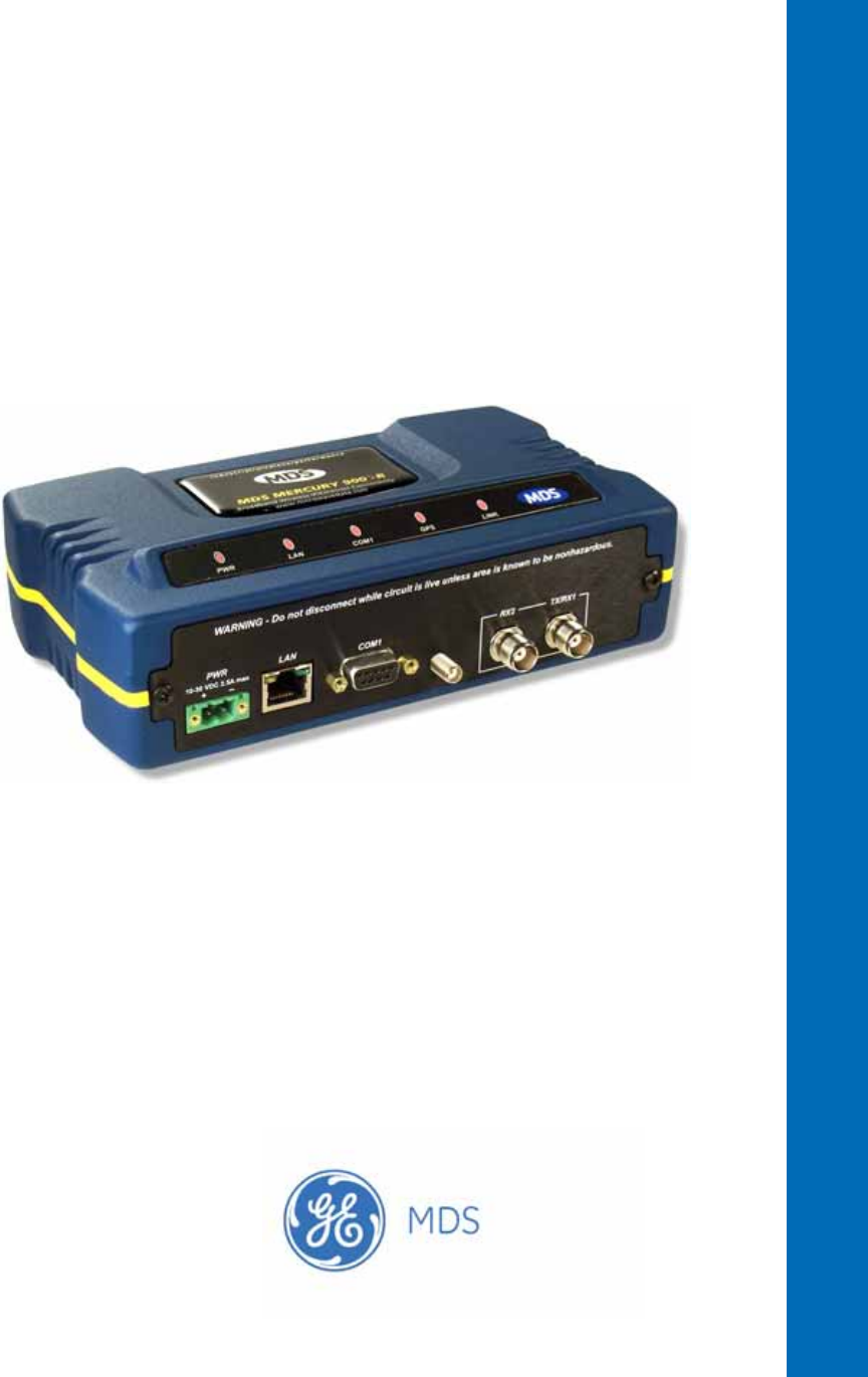
1.2 PRODUCT DESCRIPTION
The GE MDS Mercury SeriesTM transceiver (Figure 1-1) is an
easy-to-install wireless solution offering extended range, secure opera-
tion, and multi-megabit performance in a compact and rugged package.
The transceiver is ideally suited for demanding applications in fixed or
mobile environments, where reliability and range are paramount.
The transceivers are commonly used to convey text documents,
graphics, e-mail, video, Voice over IP (VoIP), and a variety of other
application data between mobile, fixed-point, and WAN/LAN-based
entities.
Based on multi-carrier Orthogonal Frequency Division Multiplexing
(OFDM), the transceiver features high speed/low latency, basic Quality
of Service (QoS) for prioritizing traffic, Ethernet and serial encapsula-
tion, and network roaming. It also provides enhanced security features
including AES encryption and IEEE 802.1x Device Authentication,
making the Mercury system the best combination of security, range, and
speed of any industrial wireless solution on the market today.
Invisible place holder
Figure 1-1. The GE MDS Mercury SeriesTM Transceiver
(Remote unit shown, AP similar in appearance)
Rugged Packaging The transceivers are housed in a compact and rugged die cast-aluminum
case that needs only protection from direct exposure to the weather. This

05-4446A01, Rev. E Mercury Reference Manual 5
one enclosure contains all necessary components for radio operation and
data communications.
Simple Installation Mercury Transceivers are designed for rapid and trouble-free installa-
tion. For basic services, you simply connect the antennas (900 or 3650
MHz as required, and GPS), connect your data equipment, apply pri-
mary power, and set some operating parameters. No license is required
for 900 MHz operation in the USA, Canada, and many other countries.
A simple registration process is required for 3650 MHz operation in the
USA. Check requirements for your region before placing the equipment
into service. (NOTE: 3650 MHz is for APs and Fixed Remote stations.)
Most installations employ an omni-directional antenna at the Access
Point (AP) location and mobile stations. Fixed Remote stations often
employ a directional antenna aimed at the AP. Regardless of the type
used, antennas are a vital part of the system and must be chosen and
installed correctly. Refer to INSTALLATION PLANNING on Page 163
for guidance on choosing suitable antennas and installation sites.
Secure Operation Data network security is a vital issue in today’s wireless world. Mercury
transceivers provide multiple tools to help you build a network that min-
imizes the risk of eavesdropping and unauthorized access. Some are
inherent in the radio’s operation, such as the use of 900 MHz
spread-spectrum transmissions; others include AES data encryption,
enabling/disabling channels, IEEE 802.1X port blocking, approved
device lists, secure devices management protocols, and password pro-
tection.
Security is not a one-step process that can simply be turned on and for-
gotten. It must be practiced and enforced at multiple levels,
24 hours-a-day and 7 days-a-week. See “GE MDS CYBER SECURITY
SUITE” on Page 17 for more information about the transceiver’s secu-
rity tools.
Robust Radio
Operation The transceivers are designed for operation in the 900 MHz license-free
Industrial, Scientific, and Medical (ISM) band and the 3650-3700 MHz
registered band. They provide consistent, reliable coverage over a large
geographic area.
Mobile range depends on many factors, including terrain, building den-
sity, antenna gain, and speed of travel. The unit is designed for suc-
cessful application in a variety of mobile environments, and offers the
best combination of range, speed and robustness available in an indus-
trial wireless package today. By using multiple Access Points, a network
can be created that provides consistent, reliable coverage over a large
metropolitan area. See “SPECIFICATIONS” on Page 178 for more
information on transmission range.
Flexible Services Users with a mix of equipment having Ethernet and serial data interfaces
can use this equipment via a Remote transceiver. The transceiver pro-
vides services in data networks that are migrating from legacy

6 Mercury Reference Manual 05-4446A01, Rev. E
serial/EIA-232-based hardware to the faster and more easily interfaced
Ethernet protocol.
Flexible
Management You can locally or remotely configure, commission, troubleshoot, and
maintain the transceiver. Four different modes of access are available:
local RS-232 console terminal, local or remote IP access (via Telnet or
SSH), web browser (HTTP, HTTPS), and SNMP (v1/v2/v3) All IP
access interfaces are available through the unit’s wired Ethernet port and
over the air.
The text-based interfaces (RS-232 console, Telnet, and SSH) are imple-
mented in the form of easy-to-follow menus, and the terminal server
provides a wizard to help you configure the units correctly.
Transceiver
Features The transceiver’s design makes the installation and configuration easy,
while allowing for future changes.
• Industrial-Grade Product—Extended temperature range for
trouble-free operation in extreme environments.
• Robust Radio Communications—Designed to operate over long
distances in dense, high-interference environments.
• Robust Network Security—Prevents common attack schemes
and hardware from gaining access or control of the network.
Common attack events are logged and reported by alarms.
• Transmission Speed—Operation at 1.5 Mbps is over 100-times
faster than 9.6 kbps radios.
• Plug-and-Play Connectivity—AP or Remote configuration
requires minimal setup.
• Built-in GPS Receiver—GPS technology is used for timing and
location data. The only external equipment needed for this func-
tionality is a GPS antenna available from GE MDS).
1.2.1 Model Offerings
The transceiver comes in two primary models—Access Point and
Remote. Unique hardware is used for each model. Of the Remote radios,
there are two sub-types available—Standard Remote and Remote
with Option Set 1, both of which support Ethernet and serial services.
Table 1-1 summarizes each radio’s interface services.
Table 1-1. Transceiver Models and Data Interface Services
Model Sub-Type Ethernet/LAN1COM11USB Integrated WiFi
Access Point N/A Yes Yes No No
Remote Standard Remote Yes Yes No No
Remote w/Option Set 1 Yes Yes Yes Yes
NOTES
1. COM1 provides access to the embedded Management System for all units.

05-4446A01, Rev. E Mercury Reference Manual 7
Available Frequency Bands
At the time of publication, Mercury transceivers are offered in two dif-
ferent frequency bands: 902-928 MHz (Mercury 900) and 3.65–3.70
GHz (Mercury 3650). The 900 MHz unit operates in a license-free spec-
trum (frequency hopping spread spectrum—FHSS), which may be used
by anyone in the USA, provided FCC Part 15 rules are observed.
Canada, and certain other countries allow license-free operation in this
band—check your country’s requirements.
The 3.65–3.70 GHz radio operates in a “registered” band using conten-
tion-based protocol, which provides additional protection from interfer-
ence, but it requires FCC registration before operation can begin. Other
restrictions may apply based on your location and “grandfathered” FSS
users. Check local requirements before operation. GE MDS has pub-
lished a whitepaper containing frequently asked questions about the
3.65–3.70 GHz band. To obtain a copy, request publication
05-4734A02. (NOTE: 3650 MHz is for APs and Fixed Remote stations.)
Operationally, the Mercury 3650 has two key differences from the Mer-
cury 900: First, it operates on a different RF band (3.65–3.70 GHz).
Second, it only requires GPS for TDD synchronization of the Access
Points, which may or may not be needed for an installation.
Access Point or Remote?—Identification Tip
The outward appearance of AP and Remote radios is nearly identical,
however, the hardware for each type is different and they are not inter-
changeable. An quick way to identify them is to observe the color of the
gasket seal in the center of the radio case. APs have a black gasket,
while Remote units have a yellow gasket.
In addition to gasket color, a label on the top of each radio identifies it
as an AP or Remote unit. If the label shows an –A suffix, it is an AP. If
it shows a –R suffix, it is a Remote.
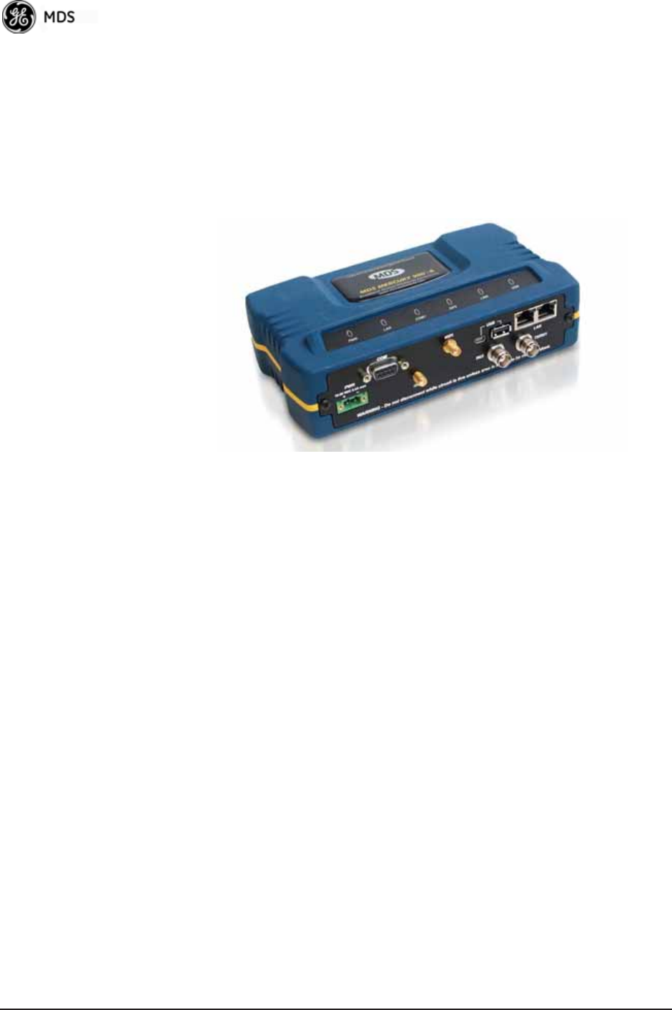
1.2.2 Remote Radio with Option Set 1
The “Option Set 1” Remote is similar to and compatible with the stan-
dard Mercury Remote. It contains the same 900 MHz radio, user inter-
face, and primary functionality as the Standard Remote. The Standard
Remote can be directly replaced with the Option Set 1 Remote. The key
differences are the additional physical interfaces: an IEEE 802.11b/g
WiFi networking module, a USB device port, a USB host port, and a
second Ethernet port on the radio enclosure.
The USB ports are used for device management. The host port accepts
a flash drive and can be used to transfer firmware and configuration
files. The two Ethernet ports are connected to an internal, integrated
switch and included in the Layer 2 bridge.
8 Mercury Reference Manual 05-4446A01, Rev. E
The internal WiFi module has FCC modular approval and may only be
operated by connecting one of the GE MDS approved antennas (see
802.11 WiFi Module Specifications below) to the reverse-SMA con-
nector on the radio’s front panel. Only these antennas may be used. The
WiFi module can operate as an 802.11 Access Point or Infrastructure
Station, according to user configuration. The operational mode (AP, Infra-
structure RM) and frequency can be configured through the unit's user
interface.
Invisible place holder
Figure 1-2. Mercury Remote with Option Set 1
(Note interface connector differences from Standard Remote)
802.11 WiFi Module Specifications
The specifications listed below are unique to Remotes with Option Set
1, which contain a 2.4 GHz WiFi module. SPECIFICATIONS on
Page 178 contains a complete list of general Mercury Series specifica-
tions.
Protocol: IEEE 802.11b/g OFDM 6 to 54Mbps, CCK 1 to
11Mbps
Frequency Range: 2400 to 2500MHz
Maximum Transmit Power: 15 dBm
Permissible Antennas: MDS 97-4278A36
MDS 97-4278A34
MDS 97-4278A35
FCC: Part 15C
FCC ID: VRA-SG9011028
WiFi Antenna Connector: Female Reverse SMA
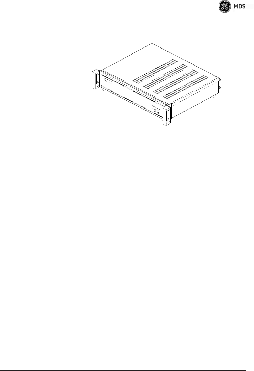
1.2.3 GE MDS P23 Protected Network (Redundant)
Configuration
For mission-critical applications, a Protected Network Station is also
offered. This unit incorporates two Access Points, two power supplies,
and a switchover logic board that automatically selects between Trans-
ceiver A and Transceiver B as the active radio. Figure 1-3 shows the
05-4446A01, Rev. E Mercury Reference Manual 9
protected chassis. For system-level information on this product, refer to
MDS publication 05-4161A01.
Invisible place holder
Figure 1-3. MDS P23 Protected Network Station
(incorporates two transceivers, with automatic switchover)
1.2.4 External GPS PPS Option
The External GPS Precise Positioning Service (PPS) option allows for
an external GPS device to provide the PPS input to the Mercury. This is
useful in installations where multiple radios require GPS timing. This
option prevents each Mercury from requiring its own GPS antenna.
Refer to the electrical specifications in the External GPS PPS Option
section on Page 180. This option is only available in hardware revision
1.0.2 or later.
1.3 APPLICATIONS
The following sections provide illustrations of typical transceiver instal-
lations. This is an overview only. A Network Administrator should be
involved in all installation planning activities.
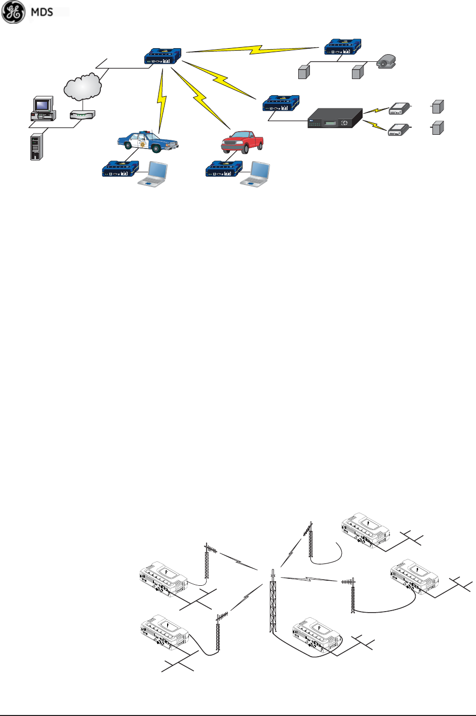
1.3.1 Mobile/Fixed Data System
Mercury transceivers support high-speed data communications in a
mobile environment. In this application, Remote radios “roam” between
different Access Points, providing seamless transitions and continuous
coverage throughout a municipal area. Figure 1-4 shows an example of
an integrated system employing both mobile and fixed Mercury trans-
ceivers.
NOTE: 3650 MHz is for APs and Fixed Remote stations only.
10 Mercury Reference Manual 05-4446A01, Rev. E
Invisible place holder
Figure 1-4. Integrated Mobile/Fixed Application
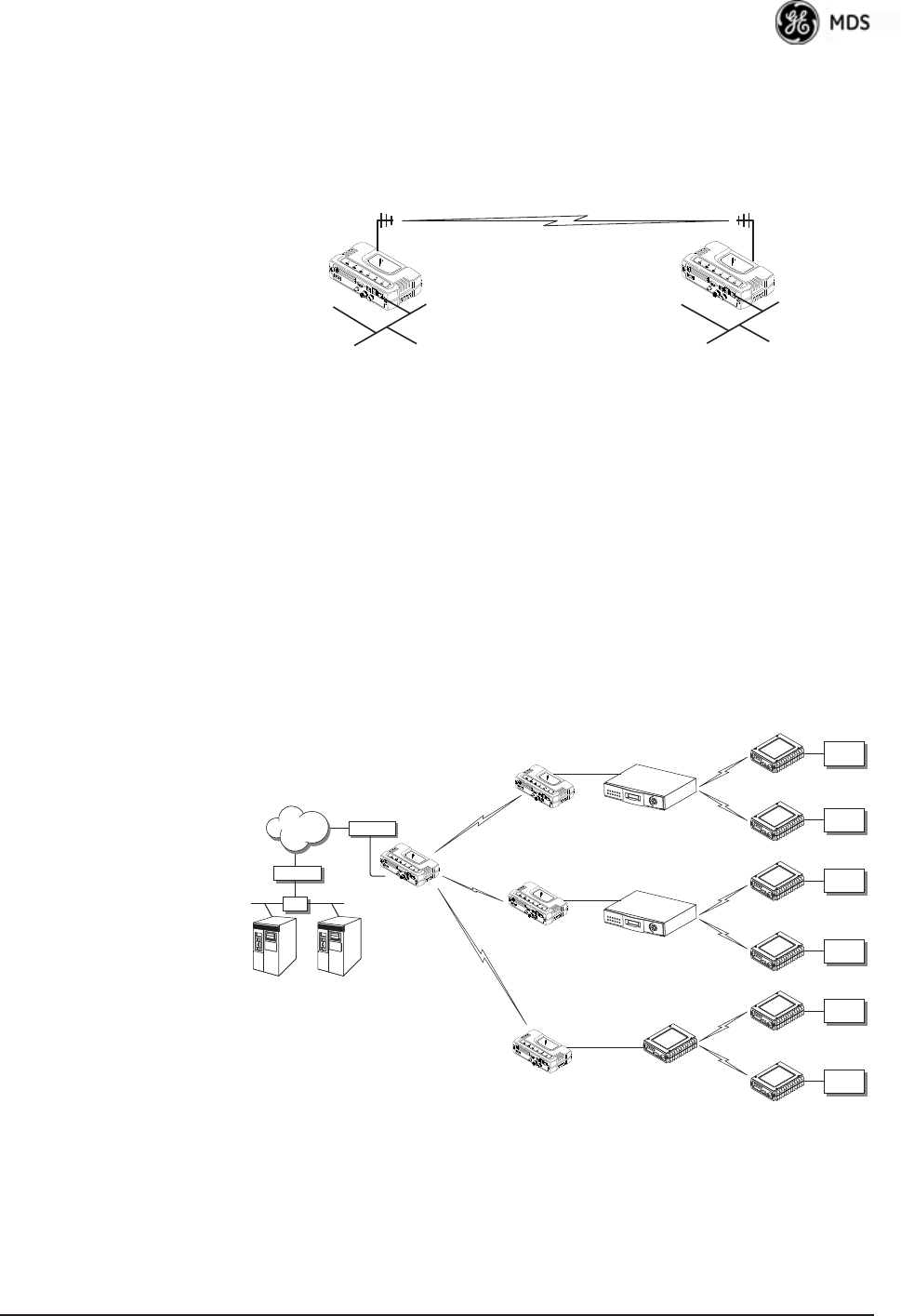
1.3.2 Wireless LAN
The wireless LAN is a common application of the transceiver. It consists
of a central control station (Access Point) and one or more associated
Remote units, as shown in Figure 1-5. A LAN provides communications
between a central WAN/LAN and remote Ethernet segments. The oper-
ation of the radio system is transparent to the computer equipment con-
nected to the transceiver.
The Access Point is positioned at a location from which it communi-
cates with all Remote units in the system. Commonly, this is a high loca-
tion on top of a building or communications tower. Messages are
exchanged at the Ethernet level. This includes all types of IP traffic.
A Remote transceiver can only communicate over-the-air to an Access
Point (AP). Peer-to-peer communications between Remotes can only
take place indirectly via the AP. In the same fashion, an AP can only
communicate over-the-air to associated Remote units. Exception: Two
APs can communicate with each other “off-the-air” through their
Ethernet connectors using a common LAN/WAN.
Invisible place holder
Figure 1-5. Typical Wireless LAN
MDS 4790
Master Radio
Licensed Serial/IP Integration
Mercury AP
MDS 4710
RTU/PLC
(Serial)
RS-232
RS-232
RS-232
MDS 4710
RTU/PLC
(Serial)
RTU/PLC
(Ethernet)
Long Range WLAN
Mobile DataMobile Data
MDS NETview MS®
Server
(Ethernet)
Computer Router
WAN
Video
Surveillance
Mercury
remote
Control Center Mercury
remote
Mercury
remote
Mercury
remote
R
emo
t
e
Remote
Access Point
Remote
Remote
LAN
LAN
WAN/LAN
LAN
LAN
05-4446A01, Rev. E Mercury Reference Manual 11
1.3.3 Point-to-Point LAN Extension
A point-to-point configuration (Figure 1-6) is a simple arrangement
consisting of an Access Point and a Remote unit. This provides a com-
munications link for transferring data between two locations.
Invisible place holder
Figure 1-6. Typical Point-to-Point Link
1.3.4 Serial Radio Network Connectivity
The transceiver provides a path for serial devices to migrate to
IP/Ethernet systems. Many radio networks in operation today still rely
on serial networks at data rates of 9600 bps or less. These networks can
use the transceiver as a means to continue using the serial service, while
allowing the infrastructure to migrate to an IP format.
A Remote transceiver with its serial port connected to a GE MDS
serial-based radio, such as the MDS x790/x710, MDS TransNET and
others, provides a path for bringing the data from the older radio into the
IP/Ethernet environment of a Mercury-based system.
Invisible place holder
Figure 1-7. Backhaul Network
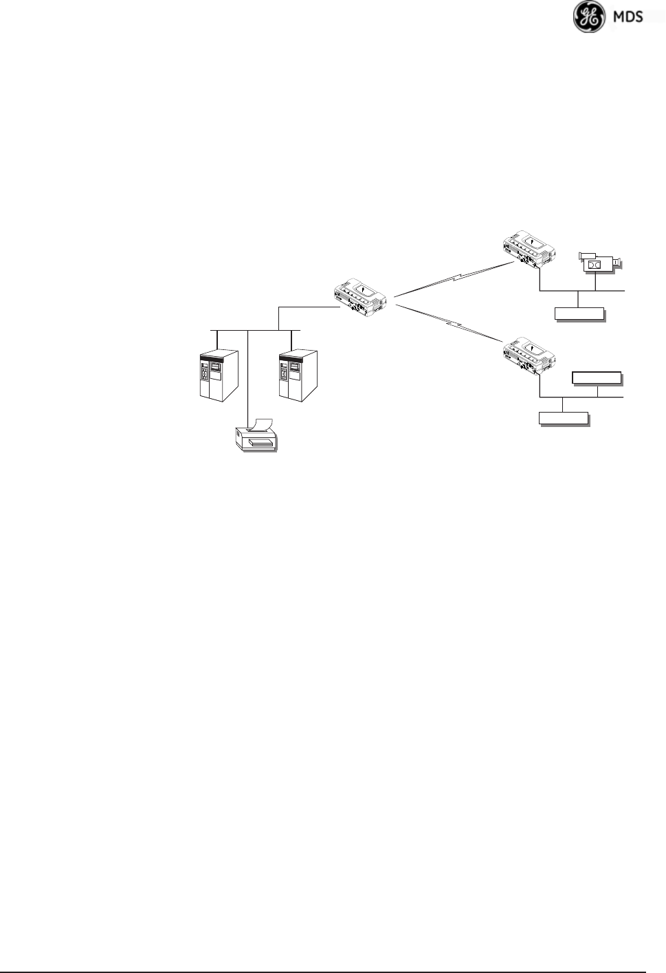
1.3.5 Multiple Protocols and/or Services
Prior to the introduction of Ethernet/IP-based radios, two radios were
often used to service two different types of devices (typically connected
LAN/WAN
Access Point Remote
LAN
MDS 4790
Master
MDS 9790
Master
MDS 9810
Master
Serial Conn.
Serial Conn.
Serial Conn.
MDS 4710 Remote
NMS Control
Point
SCADA Host
Modbus/IP
HUB Access Point
MDS 4710 Remote
MDS 9710 Remote
MDS 9710 Remote
MDS 9810 Remote
MDS 9810 Remote
Remote Serial
Remote Serial
Remote Serial
NETWORK
ROUTER
ROUTER
Serial
Device
Serial
Device
Serial
Device
Serial
Device
Serial
Device
Serial
Device
12 Mercury Reference Manual 05-4446A01, Rev. E
to different SCADA hosts). A Mercury radio provides this capability
using a single remote unit. The unit’s serial port can be connected via IP
to different SCADA hosts, transporting different (or the same) proto-
cols. Both data streams are completely independent, and the transceiver
provides seamless simultaneous operation as shown in Figure 1-8.
Invisible place holder
Figure 1-8. Multiple Protocol Network
By using a single radio, the cost of deployment is cut in half. Beyond
requiring only one radio instead of two, the biggest cost reduction comes
from using half of the required infrastructure at the remote site: one
antenna, one feedline, one lightning protector and ancillary hardware.
Other cost reductions come from the system as a whole, such as reduced
management requirements. And above all, the radio provides the poten-
tial for future applications that run over Ethernet and IP, such as video
for remote surveillance.
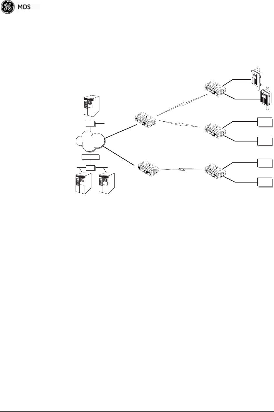
1.3.6 Wireless LAN with Mixed Services
The transceiver is an excellent solution for a long-range industrial wire-
less LAN. It offers several advantages over commercial solutions, pri-
marily improved performance over extended distances. The rugged
construction of the radio and its extended temperature range make it an
ideal solution even in harsh locations. In extreme environments, a
simple NEMA enclosure is sufficient to house the unit.
The transceiver trades higher speed for longer range. Commercial
802.11a/b/g solutions are designed to provide service to relatively small
areas such as offices, warehouses and homes. They provide high data
rates but have limited range. The Mercury transmits at a higher power
level, uses a different frequency band, has higher sensitivity, and a nar-
NETview SCADA Host
Total Flow
Access Point
Remote Serial
Remote Serial
SCADA Host
Modbus/IP
Remote Serial
Access Point
RTU
Flow Meter
EIA-232
EIA-232
EIA-232
EIA-232
EIA-232
EIA-232
ROUTER
HUB
Serial
Device
Serial
Device
Serial
Device
Serial
Device
HUB
HUB
HUB
WAN
05-4446A01, Rev. E Mercury Reference Manual 13
rower channel to concentrate the radio energy, reaching farther dis-
tances. It is designed for industrial operation from the ground up.
IP-based devices that may be used with the transceiver include new,
powerful Remote Terminal Units (RTUs) and Programmable Logic
Controllers (PLCs). These, as well as other devices, may be used in
applications ranging from SCADA/telemetry monitoring, web-based
video, security monitoring, and Voice over IP. Figure 1-9 shows a typ-
ical wireless IP network.
Invisible place holder
Figure 1-9. Extended-Range LAN with Mixed Applications
1.3.7 Upgrading Older Wireless Network with Serial
Interfaces
Millions of wireless data products have been installed in the last two
decades for licensed and license-free operation, many of them manufac-
tured by GE MDS. There are several ways that these systems can benefit
from incorporating Mercury equipment. The chief advantages are inter-
face flexibility (serial and Ethernet in one unit), and higher data
throughput. By taking advantage of its built-in serial and Ethernet inter-
faces, the transceiver is well suited to replace leased lines, dial-up lines,
or existing “multiple address” data transceivers.
Replacing Legacy Wireless Products
In most cases, legacy radio transceivers supporting serial-interface
equipment can be replaced with Mercury transceivers. Legacy equip-
ment can be connected to the transceiver through the COM1 port with a
DB-25 to DB-9 cable wired for EIA-232 signaling. The COM1 port acts
as a Data Communications Equipment (DCE) port.
NMS Control
Point
SCADA Host
Modbus/IP
Access Point
Remote Bridge
Printer
IP/Ethernet
IP/Ethernet
Remote Bridge
IP/Ethernet
IP Camera
14 Mercury Reference Manual 05-4446A01, Rev. E
NOTE: Several previous GE MDS-brand products had non-standard
signal lines on their interface connectors (for example, to
control sleep functions and alarm lines). These special func-
tions are not provided nor supported by the Mercury trans-
ceiver. Consult equipment manuals for complete pinout
information.
1.4 NETWORK DESIGN
CONSIDERATIONS
1.4.1 Extending Network Coverage with Repeaters
What is a Repeater System?
A repeater works by re-transmitting data from outlying remote sites to
the Access Point, and vice-versa. It introduces some additional
end-to-end transmission delay but provides longer-range connectivity.
In some geographical areas, obstacles can make communications diffi-
cult. These obstacles are commonly large buildings, hills, or dense
foliage. These obstacles can often be overcome with a repeater station.
Option A—Using two transceivers to form a repeater station
(back-to-back repeater)
Although the range between fixed transceivers can be up to 40 km (25
miles) over favorable terrain, it is possible to extend the range consider-
ably by connecting two units together at one site in a “back-to-back”
fashion, creating repeater as shown in Figure 1-10. Use this arrangement
whenever the objective is to utilize the maximum range between sta-
tions. In this case, using high-gain Yagi antennas at each location pro-
vides more reliable communications than their counterparts—
omnidirectional antennas.
Invisible place holder
Figure 1-10. Typical LAN with a Repeater Link
Overview Two transceivers may be connected “back-to-back” through the LAN
ports to form a repeater station. If the transceivers are connected directly
to each other, you must use an Ethernet cross-over cable. This configu-
Remote
Remote
Remote
Remote
Access
Point
Access
Point
LAN/WAN
REPEATER
Crossover Cable
LAN
LAN
LAN
Ethernet
POINT-TO-POINT LINK

05-4446A01, Rev. E Mercury Reference Manual 15
ration is sometimes required in a network that includes a distant Remote
that would otherwise be unable to communicate directly with the Access
Point station due to distance or terrain.
The geographic location of a repeater station is especially important.
Choose a site that allows good communication with both the Access
Point and the outlying Remote site. This is often on top of a hill,
building, or other elevated terrain from which both sites can be “seen”
by the repeater station antennas. A detailed discussion on the effects of
terrain is given in Section 5.1.2, Site Selection (beginning on Page 164).
The following paragraphs contain specific requirements for repeater
systems.
Antennas Two antennas are required at this type of repeater station—one for each
radio. You must take measures to minimize the chance of interference
between these antennas. One effective technique for limiting interfer-
ence is to employ vertical separation. In this arrangement, assuming
both antennas are vertically polarized, one antenna is mounted directly
over the other, separated by at least 10 feet (3 meters). This takes advan-
tage of the minimal radiation exhibited by most antennas directly above
and below their driven elements.
Another interference reduction technique is to cross-polarize the
repeater antennas. If one antenna is mounted for polarization in the ver-
tical plane, and the other in the horizontal plane, an additional 20 dB of
attenuation is achieved. The corresponding stations should use the same
antenna orientation when cross-polarization is used.
Network Name The two radios that are wired together at the repeater site must have dif-
ferent network names. For information on how to set or view the net-
work names, see “STEP 3: CONNECT PC TO THE TRANSCEIVER”
on Page 25.
TDD Sync Mode To avoid interference between the two APs that form a repeater station,
they should be synchronized so that they will transmit at the same time
and receive at the same time. This eliminates the possibility of one AP
transmitting while another is trying to receive.
This can be accomplished by setting the TDD Sync Mode parameter in the
Frequency Configuration menu to GPS Required. See Frequency Control
Menu on Page 67 for details.
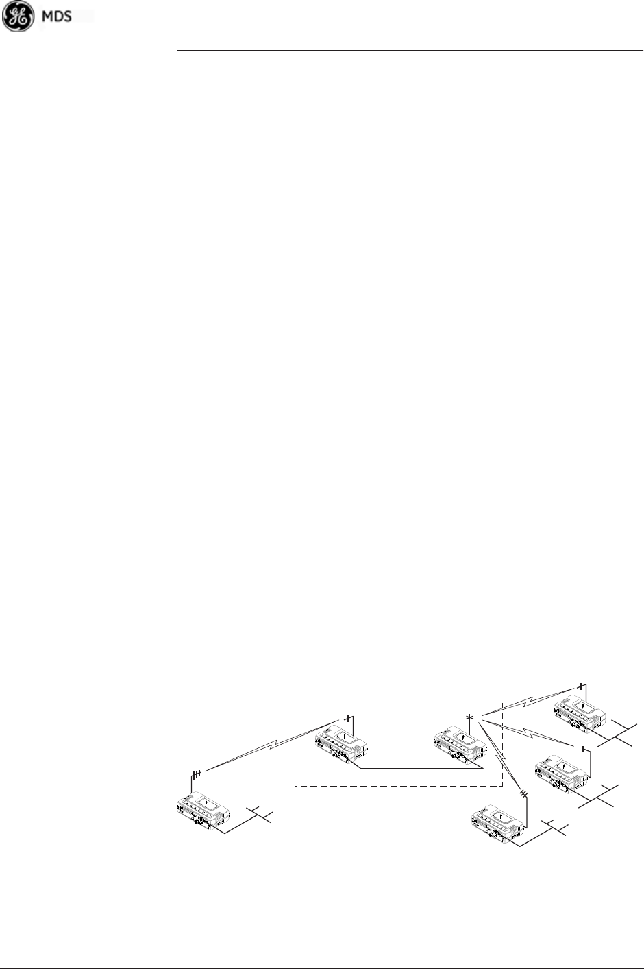
Option B—Using the AP as a Store-and-Forward Packet
Repeater
You can extend a wireless network by using the Access Point as a
repeater to re-transmit the signals of all stations in the network. (See
Figure 1-11 on Page 16.)

16 Mercury Reference Manual 05-4446A01, Rev. E
Invisible place holder
Figure 1-11. Typical Store-and-Forward Repeater Arrangement
As with the conventional repeater described in Option 1 above, the loca-
tion of a store and forward repeater is also important. A site must be
chosen that allows good communication with both the Access Point and
the outlying Remote site. This can be on the top of a hill, building, or
other elevated terrain from which all sites can be “seen” by the repeater
station antenna. A detailed discussion on the effects of terrain is given
in Section 5.1.2, Site Selection (beginning on Page 164).
1.4.2 Protected Network Operation using Multiple
APs
Although GE MDS transceivers have a very robust design and have
undergone intensive testing before being shipped, it is possible for iso-
lated failures to occur. In mission-critical applications, down time can
be virtually eliminated by using some, or all, of the following configu-
rations:
In a point-to-multipoint scenario, the Access Point services multiple
remotes. A problem in the Access Point will have an effect on all
remotes, since none will have access to the network. When operation of
the network does not tolerate any down time, it is possible to set up a
protected configuration for the Access Point to greatly reduce the possi-
bility of this occurrence.
Two or more Access Points can be configured identically, each with its
own independent antenna. In this scenario, Remotes will associate with
one of the available Access Points. In case of a failure of that AP, the
Remotes will quickly associate with another Access Point, re-estab-
lishing connectivity to the end devices. Because only one Access Point
operates at any given time, collisions between APs is not possible.
1.4.3 Collocating Multiple Radio Networks
Many networks can operate in relatively close physical proximity to one
another provided reasonable measures are taken to assure the radio
signal of one Access Point is not directed at the antenna of the second
Access Point.
Remote
Remote
Remote
Remote
Access Point
LAN/WAN
REPEATER
LAN
LAN
LAN

05-4446A01, Rev. E Mercury Reference Manual 17
The Network Name and the Association Process
The Network Name is the foundation for building individual radio net-
works. Remotes in a network with the same network name as an Access
Point (AP) unit are “associated” with that AP.
The use of a different Network Name does not guarantee an interfer-
ence-free system. It does, however, assure that only data destined for a
unique network is passed through to that network.
Co-Location for
Multiple Networks It may be desirable to co-locate Access Points at one location to take
advantage of an excellent location that can serve two independent net-
works. Configure each network with a unique Network Name, and
install each AP’s antenna with at least 10 feet of vertical separation to
minimize RFI.
To co-locate APs, configure them with Time Division Duplex (TDD)
Sync set to GPS Required. Configure all APs that are within range of each
other with the same pattern, but with a unique Hop Pattern Offset. For
more information, see “Frequency Control Menu” on Page 67.
NOTE: Transceivers are shipped with the Network Name set to
MDS-Mercury as a factory default.
Can radio frequency interference (RFI) disrupt my wireless
network?
When multiple radio networks operate in close physical proximity to
other wireless networks, individual units may not operate reliably under
weak signal conditions and may be influenced by strong radio signals on
adjacent bands. This radio frequency interference cannot be predicted
with certainty, and can only be determined by experimentation. If you
need to co-locate two units, start by using the largest possible vertical
antenna separation between the two AP antennas on the same support
structure. If that does not work, consult with your factory representative
about other techniques for controlling radio frequency interference
between the radios. (See “A Word About Radio Interference” on
Page 170 for more details.)
1.5 GE MDS CYBER SECURITY SUITE
Today, the operation and management of an enterprise is increasingly
dependent on electronic information flow. An accompanying concern
becomes the cyber security of the communication infrastructure and the
security of the data itself.

18 Mercury Reference Manual 05-4446A01, Rev. E
The transceiver is capable of dealing with many common security
issues. Table 1-2 profiles security risks and how the transceiver pro-
vides a solution for minimizing vulnerability.
Table 1-2. Security Risk Management
Security Vulnerability GE MDS Cyber Security Solution
Unauthorized access to the backbone
network through a foreign remote radio • IEEE 802.1x device authentication
• Approved Remotes List (local)
Only those remotes included in the
AP list will associate
“Rogue” AP, where a foreign AP takes
control of some or all remote radios and
thus remote devices
• IEEE 802.1x device authentication
• Approved AP List
A remote will only associate to those
APs included in its local authorized
list of APs
Dictionary attacks, where a hacker runs a
program that sequentially tries to break a
password.
• Failed-login lockdown
After five tries, the transceiver
ignores login requests for 5 minutes.
Critical event reports (traps) are
generated as well.
Denial of service, where Remote radios
could be reconfigured with bad
parameters, bringing the network down.
• Remote login with SSH or HTTPS
• Local console login
• Disabled HTTP and Telnet to allow
only local management services
Airsnort and other war-driving hackers in
parking lots, etc. • Operation is not interoperable with
standard 802.11 wireless cards
• The transceiver cannot be put in a
promiscuous mode
• Proprietary data framing
Eavesdropping, intercepting messages • AES-128 encryption
Unprotected access to configuration via
SNMPv1 • Implement SNMPv3 secure
operation
Intrusion detection •Provides early warning via SNMP
through critical event reports
(unauthorized, logging attempts,
etc.)
•Unauthorized AP MAC address
detected at Remote
•Unauthorized Remote MAC
address detected at AP
•Login attempt limit exceeded
(Accessed via: Telnet, HTTP, or
local)
•Successful login/logout
(Accessed via: Telnet, HTTP, or
local)

05-4446A01, Rev. E Mercury Reference Manual 19
1.6 ACCESSORIES
The transceiver can be used with one or more of the accessories listed in
Table 1-3. Contact the factory for ordering details.
Table 1-3. Accessories
Accessory Description GE MDS
Part No.
AC Power
Adapter Kit
A small power supply module designed for
continuous service. UL approved. Input:
120/220; Output: 13.8 Vdc @ 2.5 A
01-3682A02
Omni-
Directional
Antennas
Rugged antennas well suited for use at Access
Point installations. Consult with your factory
Sales Representative for details
--
Yagi Antenna
(Directional)
Rugged antennas well suited for use at fixed
Remote sites. Consult with your factory Sales
Representative for details.
--
GPS Receiving
Antennas
A variety of fixed and mobile GPS antennas
(active and passive) are available. Consult with
your factory Sales Representative for details.
--
TNC Male-to-N
Female Adapter
One-piece RF adaptor plug. 97-1677A161
TNC Male-to-N
Female Adapter
Cable
Short length of coaxial cable used to connect
the radio’s TNC antenna connector to a Type N
commonly used on large diameter coaxial
cables.
97-1677A159
(3 ft./1m)
97-1677A160
(6 ft./1.8m)
Ethernet RJ-45
Crossover
Cable (CAT5)
Cable assembly used to cross-connect the
Ethernet ports of two transceivers used in a
repeater configuration.
(Cable length ≈ 3 ft./1M)
97-1870A21
2-Pin Power
Plug
Mates with power connector on transceiver.
Screw terminals provided for wires, threaded
locking screws to prevent accidental disconnect.
73-1194A39
Ethernet RJ-45
Straight-thru
Cable (CAT5)
Cable assembly used to connect an Ethernet
device to the transceiver. Both ends of the cable
are wired identically.
(Cable length ≈ 3 ft./1M)
97-1870A20
EIA-232
Shielded Data
Cable
Shielded cable terminated with a DB-25 male
connector on one end, and a DB-9 female on the
other end. Two lengths available (see part
numbers at right).
97-3035L06
(6 ft./1.8m)
97-3035L15
(15 ft./4.6m)
EIA-232
Shielded Data
Cable
Shielded cable terminated with a DB-9 male
connector on one end, and a DB-9 female on the
other end, 6 ft./1.8m long.
97-1971A03
Flat-Surface
Mounting
Brackets &
Screws
Brackets: 2˝ x 3˝ plates designed to be screwed
onto the bottom of the unit for surface-mounting
the radio.
82-1753-A01
Bracket screws: 6-32/1/4˝ with locking adhesive.
(Industry Standard MS 51957-26)
70-2620-A01
Fuse Internal fuse, 5.0 Ampere 29-1784A04

20 Mercury Reference Manual 05-4446A01, Rev. E
DIN Rail
Mounting
Bracket
Bracket used to mount the transceiver to
standard 35 mm DIN rails commonly found in
equipment cabinets and panels.
03-4022A03
COM1 Interface
Adapter
DB-25(F) to DB-9(M) shielded cable assembly
(6 ft./1.8 m) for connection of equipment or other
EIA-232 serial devices previously connected to
“legacy” units. (Consult factory for other lengths
and variations.)
97-3035A06
Bandpass Filter Antenna system filter that helps eliminate
interference from nearby paging transmitters.
20-2822A02
Ethernet Surge
Suppressor
Surge suppressor for protection of Ethernet port
against lightning.
29-4018A01
Table 1-3. Accessories (Continued)
Accessory Description GE MDS
Part No.

05-4446A01, Rev. E Mercury Reference Manual 21
2TABLETOP EVALUATION
AND TEST SETUP
2 Chapter Counter Reset Paragraph
Contents
2.1 OVERVIEW ........................................................................... 23
2.2 STEP 1—CONNECT THE ANTENNA PORTS...................... 23
2.3 STEP 2—CONNECT THE PRIMARY POWER ..................... 24
2.4 STEP 3—CONNECT PC TO THE TRANSCEIVER............... 25
2.5 STEP 4—REVIEW TRANSCEIVER CONFIGURATION ....... 25
2.5.1 Getting Started ....................................................................... 25
2.5.2 Procedure ............................................................................... 25
2.5.3 Basic Configuration Defaults .................................................. 25
2.6 STEP 5—CONNECT LAN OR SERIAL DATA EQUIPMENT. 26
2.6.1 Option Set 1 Connectors ........................................................ 28
2.7 STEP 6—CHECK FOR NORMAL OPERATION ................... 29

22 Mercury Reference Manual 05-4446A01, Rev. E
05-4446A01, Rev. E Mercury Reference Manual 23
2.1 OVERVIEW
GE MDS recommends that you set up a “tabletop network” to verify the
basic operation of the transceivers. This allows experimenting with net-
work designs, configurations, or network equipment in a convenient
location. This test can be performed with any number of radios.
When you are satisfied that the network is functioning properly in a
benchtop setting, perform the field installation. Complete information
for field installation, including mounting dimensions and antenna selec-
tion, is provided in INSTALLATION PLANNING on Page 163.
NOTE: It is important to use a “Network Name” that is different from
any currently in use in your area during the testing period.
To simulate data traffic over the radio network, connect a PC or LAN to
the Ethernet port of the Access Point and PING each transceiver several
times.
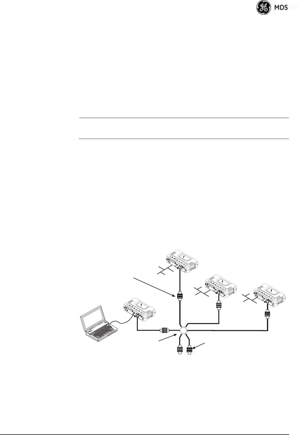
2.2 STEP 1: CONNECT THE ANTENNA
PORTS
Figure 2-1 shows the tabletop arrangement. Connect the antenna ports
of each transceiver as shown. This provides stable radio communica-
tions between each unit and prevents interference to nearby electronic
equipment.
Invisible place holder
Figure 2-1. Typical Setup for Tabletop-Testing of Radios
POWER ATTENUATORS
• Fixed or adjustable
• 2W Minimum Rating
POWER DIVIDER
NON-RADIATING ATTENUATORS
• Install on unused divider ports (if any)
• 2W Minimum Rating
COMPUTER
Remote
Remote
Access Point
Remote
24 Mercury Reference Manual 05-4446A01, Rev. E
NOTE: Use attenuation between all units in the test setup. The amount
of attenuation required depends on the number of units tested
and the desired signal strength (RSSI) at each transceiver
during the test. In no case should a signal greater than –50 dBm
be applied to any transceiver in the test setup. GE MDS recom-
mends an RF power output level of +20 dBm from the AP.
Remote power is not setable. (See “Radio Configuration
Menu” on Page 65.)
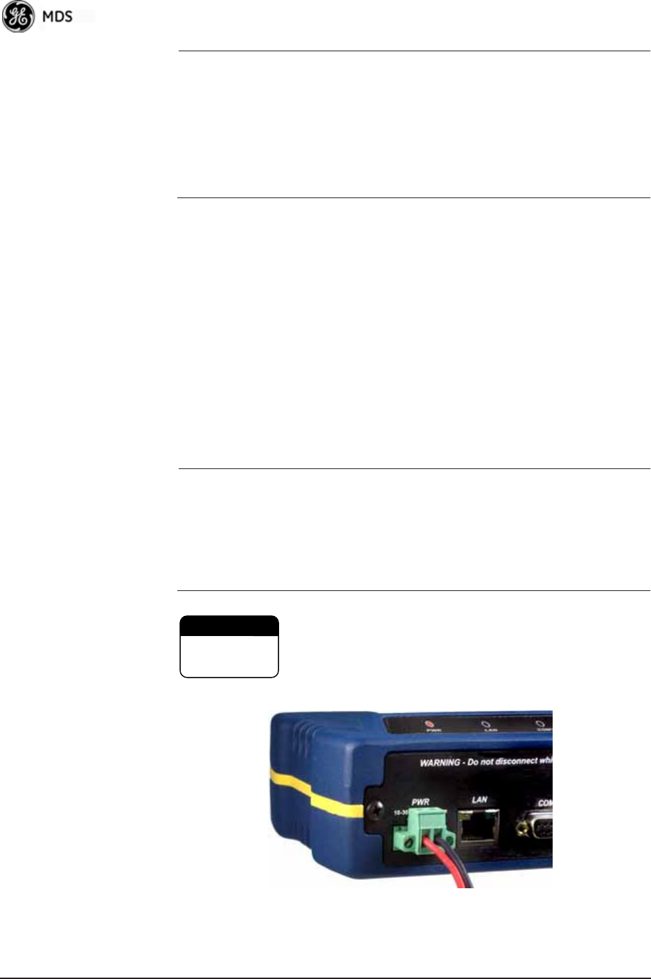
2.3 STEP 2: CONNECT THE PRIMARY
POWER
The primary power at the transceiver’s power connector must be within
10.5–30 Vdc and be capable of continuously providing 30 Watts. Typ-
ical power consumption for 13.8 Vdc and 24 Vdc operation are listed in
SPECIFICATIONS on Page 178.
A Phoenix two-pole power connector with screw-terminals is provided
with each unit. Strip the wire leads to 6 mm (0.25"). Be sure to observe
proper polarity with the positive lead (+) on the left and negative (–) on
the right, as shown in Figure 2-2.
NOTE: The transceiver typically requires about 30 seconds to power up, and
might require several minutes to associate with another unit, if GPS
is required for time synchronization.
GPS is required for all configurations except when “Free Run”
single-channel (non-frequency hopping) operation is used, which
might be possible in some low-interference environments.
Only use the transceiver with negative-ground power
systems. Make sure the polarity of the power source
is correct.
Invisible place holder
Figure 2-2. Power Connector
(Polarity: Left +, Right —)
CAUTION
POSSIBLE
EQUIPMENT
DAMAGE

05-4446A01, Rev. E Mercury Reference Manual 25
2.4 STEP 3: CONNECT PC TO THE
TRANSCEIVER
Connect a PC’s Ethernet port to the LAN port using an Ethernet cross-
over cable. The LAN LED should light. Alternatively, you can use a
serial cable to connect to the COM1 port (Figure 2-3 on Page 27).
2.5 STEP 4: REVIEW TRANSCEIVER
CONFIGURATION
2.5.1 Getting Started
Start by logging into the Access Point radio. This is done first because
the Remotes are dependent on the AP’s beacon signal to achieve an
“associated” state.
Once the Access Point is up and running, move the computer connection
to each of the Remote units, log-in at each unit, review their configura-
tion, set their IP addresses, Network Name, and frequency configura-
tion, then wait for each AP to achieve an associated state.
With all units associated, you will be ready to connect and test your data
services.
2.5.2 Procedure
The following is a summary of the configuration procedure that must be
done on each unit in the system. Key parameters are shown on the
Embedded Management System overview (Figure 3-1 on Page 34). A
lists of parameters is located in two tables—Table 4-5 on Page 154 and
Table 4-7 on Page 156. Detailed information on using the Management
System can be found in INTRODUCTION on Page 33.
NOTE: The Management System supports the use of “configuration
files” to help consistently configure multiple units. These are
explained in Configuration Scripts Menu on Page 131.
2.5.3 Basic Configuration Defaults
Table 2-1 provides a selection of key operating parameters, their range,
and default values. All of these are accessible through a terminal emu-
lator connected to the COM1 serial port or through a Web browser con-
nected to the LAN port (see Figure 5-1 on Page 163 for hookup).
NOTE: Access to the transceiver’s Management System and changes
to all parameters requires entering a security password.

26 Mercury Reference Manual 05-4446A01, Rev. E
For benchtop evaluation, configure:
•Frequency Mode = Single Channel
•Single Frequency Channel = 0
•RF Bandwidth = 1.75
•TDD Sync = Free Run
For more information on configuring these parameters, see “Frequency
Control Menu” on Page 67.
A unique IP address and subnet are required to access all IP-based man-
agement interfaces (telnet, SSH, SNMP, and Web), either through the
LAN port or remotely over-the-air.
2.6 STEP 5: CONNECT LAN OR
SERIAL DATA EQUIPMENT
Connect a local area network to the LAN port or a serial device to the
COM1 (DCE) port. The LAN port supports any Ethernet-compatible
equipment. This includes devices that use Internet Protocol (IP).
Figure 2-3 on Page 27 shows the interface connectors on the front panel
of the standard transceiver (Remote). The Option Set 1 Remote connec-
tors are shown in Figure 2-4 on Page 28.
NOTE: The use of shielded Ethernet cable is recommended for
connection to the radio’s ETH port. The radio meets regulatory
emission standards without shielded cable, but shielding
reduces the possibility of interference in sensitive environ-
ments, and is in keeping with good engineering practice.
Table 2-1. Basic Configuration Defaults
Item Menu Location Default Values/Range
Network Name Main Menu>>
Radio Configuration>>
Network Name
MDS-Mercury • 1–15 alphanumeric
characters
• Case-sensitive;
can be mixed case
IP Address Main Menu>>
Network Configuration>>
IP Address
192.168.1.1 Contact your network
administrator
RF Output
Power
Main Menu>>
Radio Configuration>>
Transmit Power
+29 dBm (900 model)
+23 dBm (3650 model)
AP: -30 to +29 dBm
RM: 0 to +29 dBm
Unit Password Main Menu>>
Device Information>>
User Password
admin
(lower case)
• 1–13 alphanumeric
characters
• Case-sensitive;
can be mixed case
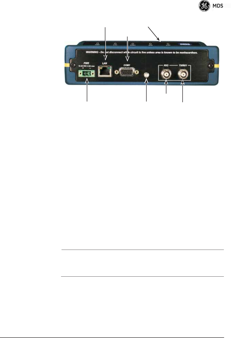
05-4446A01, Rev. E Mercury Reference Manual 27
Invisible place holder
Figure 2-3. Transceiver Interface Connectors
(Standard unit shown; See Figure 2-4 on Page 28 for Option Set 1 unit)
•LED INDICATOR PANEL—Displays the basic operating status of
the transceiver. See section 2.7 on Page 29 for detailed informa-
tion.
•COM1 SERIAL PORT— DB-9 connector used for management
of the transceiver with a connected PC. INTRODUCTION on
Page 33 provides complete connection details.
•LAN PORT—Connection point for Ethernet Local Area Net-
work. The connector has integrated LEDs to indicate signal
activity as follows: A steady green LED indicates that a link has
been achieved; a flashing green LED indicates data activity; and
a yellow LED indicates 100 Mbps operation.
•PWR— DC power connection for the transceiver. Power source
must be 10 Vdc to 30 Vdc, negative ground, and capable of pro-
viding at least 25 watts.
•GPS ANTENNA PORT— Coaxial connector (SMA-type) for
connection of a GPS receiving antenna. Provides 3.5 Vdc output
for compatibility with powered (active) GPS antennas. The GPS
receiving antenna’s gain must be 16 dBi or less.
NOTE: GPS functionality is required on all Access Points and
Remotes except when “Free Run” single-channel (non-frequency
hopping) operation is used, which might be possible in some
low-interference environments.
•RX2 ANTENNA PORT— Coaxial connector (TNC-type) for
attachment of a second receiving antenna used in space diver-
sity arrangements.
•TX/RX1 ANTENNA PORT— Coaxial connector (TNC-type) for
attachment of the main station antenna (transmit and receive).
COM1
SERIAL PORT
LAN PORT
GPS ANTENNA
CONNECTION
RX2 ANTENNA
PORT
TX/RX1
ANTENNA PORT
DC POWER INPUT
(10—30 VDC, 2.5A)
LED INDICATOR
PANEL
28 Mercury Reference Manual 05-4446A01, Rev. E
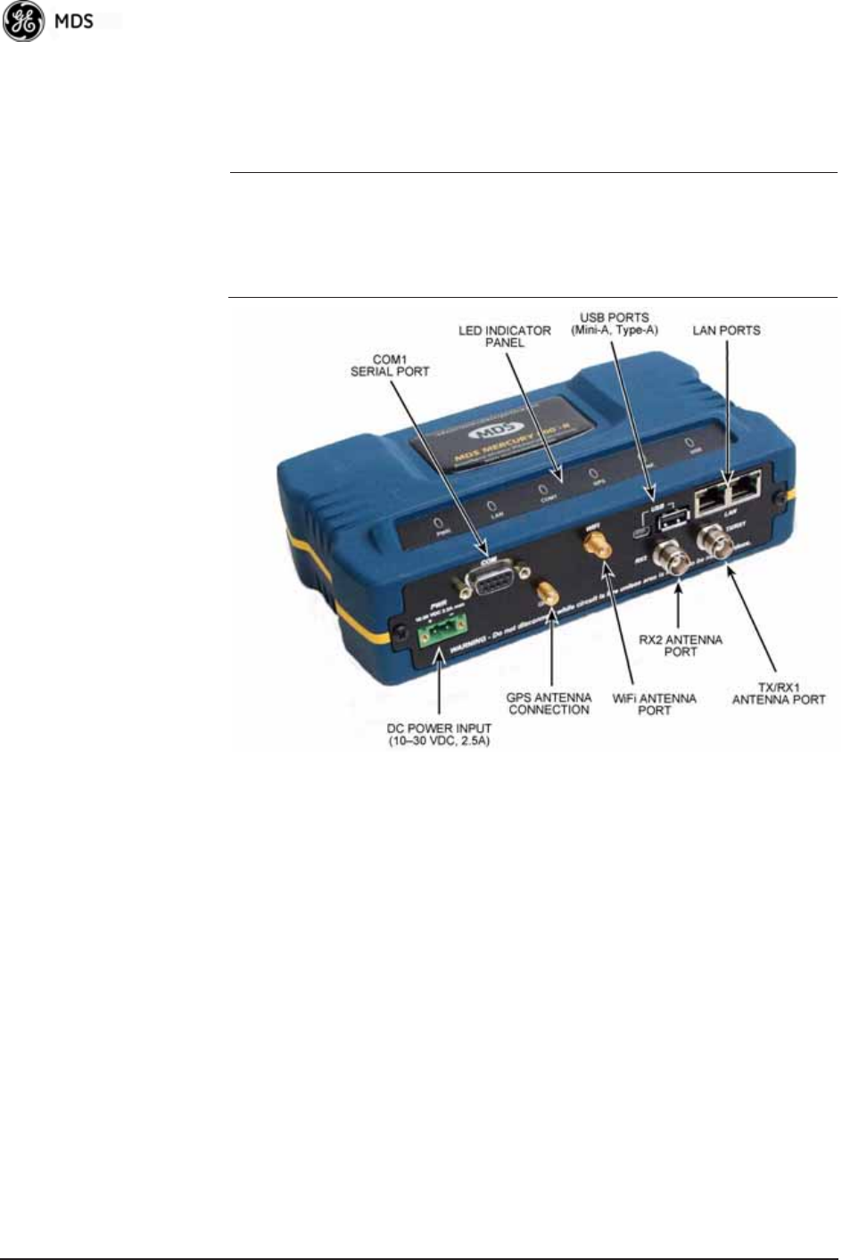
2.6.1 Option Set 1 Connectors
Figure 2-4 shows the interface connectors on the front panel of the
Option Set 1 Remote transceiver.
NOTE: The use of shielded Ethernet cable is recommended for
connection to the radio’s ETH port. The radio meets regulatory
emission standards without shielded cable, but shielding
reduces the possibility of interference in sensitive environ-
ments, and is in keeping with good engineering practice.
Invisible place holder
Figure 2-4. Option Set 1 Transceiver
Interface Connectors
•LED INDICATOR PANEL—Displays the basic operating status of
the transceiver. See section 2.7 on Page 29 for detailed informa-
tion.
•COM1 SERIAL PORT— DB-9 connector used for management
of the transceiver with a connected PC. INTRODUCTION on
Page 33 provides complete connection details.
•LAN PORTS—Connection point for Ethernet Local Area Net-
work. The connectors have integrated LEDs to indicate signal
activity as follows: A steady green LED indicates that a link has
been achieved; a flashing green LED indicates data activity; and
a yellow LED indicates 100 Mbps operation.
•PWR— DC power connection for the transceiver. Power source
must be 10 Vdc to 30 Vdc, negative ground, and capable of pro-
viding at least 25 watts.

05-4446A01, Rev. E Mercury Reference Manual 29
•GPS ANTENNA PORT— Coaxial connector (SMA-type) for
connection of a GPS receiving antenna. Provides 3.5 Vdc output
for compatibility with powered (active) GPS antennas. Do not
short this connector, as you might cause damage to the internal
power supply. The GPS receiving antenna’s gain must be
16 dBi or less.
NOTE: GPS functionality is required on all Access Points and
Remotes except when “Free Run” single-channel (non-frequency
hopping) operation is used, which might be possible in some
low-interference environments.
•WiFi ANTENNA PORT— Coaxial connector (SMA-type) for
attachment of a WiFi antenna. WiFI is typically used for short
range wireless communication at the transceiver site or within a
small area around the site.
•RX2 ANTENNA PORT— Coaxial connector (TNC-type) for
attachment of a second receiving antenna used in space diver-
sity arrangements.
•TX/RX1 ANTENNA PORT— Coaxial connector (TNC-type) for
attachment of the main station antenna (transmit and receive).
2.7 STEP 6: CHECK FOR NORMAL
OPERATION
Once the data equipment is connected, you can check the transceiver for
normal operation.
Observe the LEDs on the top cover for the proper indications. In a nor-
mally operating system, you will see the following LED indications
within 45 seconds of start-up:
•PWR—Lit continuously
•LINK—On, or blinking intermittently to indicate traffic flow
•LAN—On, or blinking intermittently to indicate traffic flow
Figure 2-5 shows a close-up view of the transceiver’s LED Indicator
panel. Table 2-2 provides details on each LED function.
Invisible place holder
Figure 2-5. LED Indicator Panel

30 Mercury Reference Manual 05-4446A01, Rev. E
If the radio network seems to be operating properly based on observa-
tion of the unit’s LEDs, use the PING command to verify the link integ-
rity with the Access Point.
* The LAN connector has two integrated LEDs to indicate signal activity
as follows: A steady green LED indicates that a link has been achieved;
a flashing green LED indicates data activity, and a yellow LED indicates
100 Mbps operation.
Table 2-2. Transceiver LED Functions
LED Label Activity Indication
PWR ON Primary power (DC) present
Blinking Unit in “Alarmed” state
OFF Primary power (DC) absent
LAN* ON LAN detected
Blinking Data TX/RX
OFF LAN not detected, or excessive
traffic present
COM1
(MGT System)
Blinking Data TX/RX
OFF No data activity
GPS ON Internal GPS receiver is
synchronized with the satellite
network.
Blinking AP modem is synchronizing
with the GPS timing.
OFF Internal GPS receiver is not
synchronized with the satellite
network.
LINK
(Access Point)
ON Unit is operational
OFF Not transmitting. Usually
occurs while waiting for GPS
sync.
LINK
(Remote)
ON Associated to AP
OFF Not associated with AP
USB ON USB activity on either port
OFF No USB activity

05-4446A01, Rev. E Mercury Reference Manual 31
3DEVICE MANAGEMENT
3 Chapter Counter Reset Paragraph
Contents
3.1 INTRODUCTION .....................................................................33
3.1.1 Differences in the User Interfaces ............................................33
3.2 ACCESSING THE MENU SYSTEM ........................................ 35
3.2.1 Methods of Control ................................................................... 36
3.2.2 PC Connection and Log In Procedures ...................................36
3.2.3 Navigating the Menus .............................................................. 40
3.3 BASIC OVERVIEW OF OPERATION......................................42
3.3.1 Starting Information Screen ..................................................... 42
3.3.2 Main Menu ............................................................................... 43
3.4 CONFIGURING NETWORK PARAMETERS .......................... 45
3.4.1 Network Configuration Menu ...................................................45
3.4.2 Ethernet Port Configuration Menu ...........................................56
3.4.3 Bridge Configuration ................................................................ 58
3.4.4 SNMP Agent Configuration ...................................................... 58
3.4.5 AP Location Push Config Menu ............................................... 60
3.4.6 SNTP Server Configuration ......................................................64
3.5 RADIO CONFIGURATION ...................................................... 65
3.5.1 Radio Configuration Menu ....................................................... 65
3.5.2 Serial Port Configuration ..........................................................76
3.6 MODBUS / TCP SERVER CONFIGURATION ........................ 88
3.6.1 Modbus/TCP in Mercury TransceiversAn Overview .............88
3.6.2 Menu Selections .......................................................................89
3.7 SECURITY CONFIGURATION MENU ....................................92
3.7.1 Device Security Menu .............................................................. 93
3.7.2 Wireless Security Menu ........................................................... 95
3.7.3 IEEE 802.1x Device Authentication .........................................97
3.7.4 Manage Certificates ................................................................. 99
3.8 REDUNDANCY CONFIGURATION (AP ONLY)......................102
3.9 GPS CONFIGURATION (REMOTE ONLY).............................107

32 Mercury Reference Manual 05-4446A01, Rev. E
3.10 DEVICE INFORMATION MENU............................................109
3.11 PERFORMANCE INFORMATION MENU .............................110
3.12 MAINTENANCE/TOOLS MENU............................................123
3.12.1 Installing Firmware via TFTP ................................................ 129
3.12.2 Auto Firmware Upgrade Menu (AP Only) ..............................138
3.13 PERFORMANCE OPTIMIZATION ........................................ 140
3.13.1 Proper OperationWhat to Look For .................................... 143

05-4446A01, Rev. E Mercury Reference Manual 33
3.1 INTRODUCTION
The transceiver’s embedded management system is accessible through
the COM1 (serial) port, the LAN (Ethernet) port, and using over-the-air
Ethernet. Telnet, SSH, HTTP/HTTPS, and SNMP are the
Ethernet-based interfaces. Essentially, the same capabilities are avail-
able through any of these paths.
For support of SNMP software, a set of MIB files is available for down-
load from the GE MDS Web site at www.GEmds.com. An overview of
SNMP commands can be found at SNMP Agent Configuration section
on Page 58 of this manual.
The transceiver’s Management System and its functions are divided into
seven functional groups as listed below.
•Section 3.3, BASIC OVERVIEW OF OPERATION (beginning
on Page 42)
•Section 3.4, CONFIGURING NETWORK PARAMETERS
(beginning on Page 45)
•Section 3.5, RADIO CONFIGURATION (beginning on Page
65)
•Section 3.7, SECURITY CONFIGURATION MENU (beginning
on Page 92)
•Section 3.13, PERFORMANCE OPTIMIZATION (beginning on
Page 140)
•Section 3.12, MAINTENANCE/TOOLS MENU (beginning on
Page 123)
Each of these sections has a focus that is reflected in its heading. The
section you are now reading provides information on connecting to the
Management System, how to navigate through it, how it is structured,
and how to perform top-level configuration tasks. Figure 3-1 on Page 34
shows a top-level view of the Management System (MS).
3.1.1 Differences in the User Interfaces
Although there are slight differences in navigation among the user inter-
faces, the content is very similar. You will notice a few differences in
capabilities as the communications tool is driven by limitations of the
access channel. Figure 3-2 and Figure 3-3 on Page 35 show examples of
the Starting Information Screen as seen through a console terminal and
a web-browser, respectively.
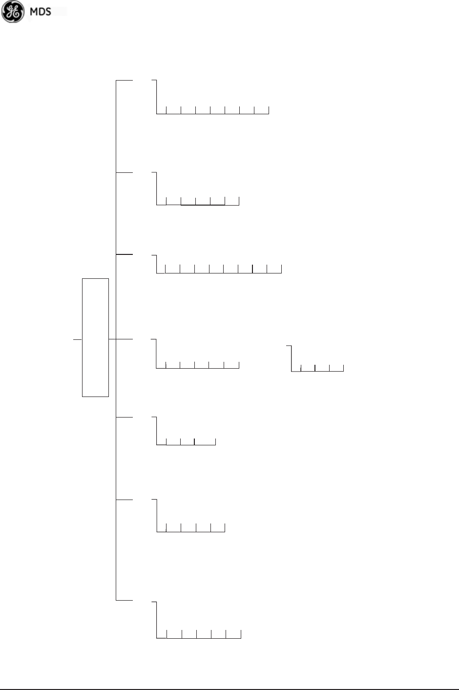
34 Mercury Reference Manual 05-4446A01, Rev. E
• Spacebar is used to make some menu selections
• AP = Access Point Only
• RM = Remote Only
Ntwk. Intfc. Config
Ethernet Port Config
Bridge Configuration
SNMP Agent Config. (AP)
AP Location Info (RM)
SNTP Server Config.
Network
Configuration Radio
Configuration Device
Information Maintenance/Tools
Security
Configuration
Reprogramming
Config. Scripts
Ping Utility
Auth. Codes
Reset to Defaults
Radio Test
F/W Versions
F/W Upgrade
MAIN MENU
Network Name
Transmit Power
Receive Pwr. (AP)
Freq. Control
Adv. Config.
Performance
Information
NOTES
• Chart shows top-level view only. See Reference Manual for details.
• Not all menu items are-user configurable
Serial Number
Uptime
Date
Date Format
Time
Model
Device Names
Console Bd. Rt.
UTC Time Offset
Device Security
Wireless Security
Event Log
Packet Statistics
GPS Status
Wireless Ntwk Stat.
Intl. Radio Stat. (RM)
Performance Trend
Manage Certif.
RADIUS
Configuration
Starting Information Screen
(Read-Only Status)
Redundancy
Configuration (AP)
Redundancy Config.
Ntwk Event Triggers
Radio Event Triggers
Hdwr Event Triggers
Red. Config. Options
Force Switchover
GPS
Configuration (RM)
Stream GPS to Console
Send GPS via UDP
GPS UDP Server IP Address
GPS UDP Server UDP Port
Figure 3-1. Embedded Management SystemTop-Level Flowchart
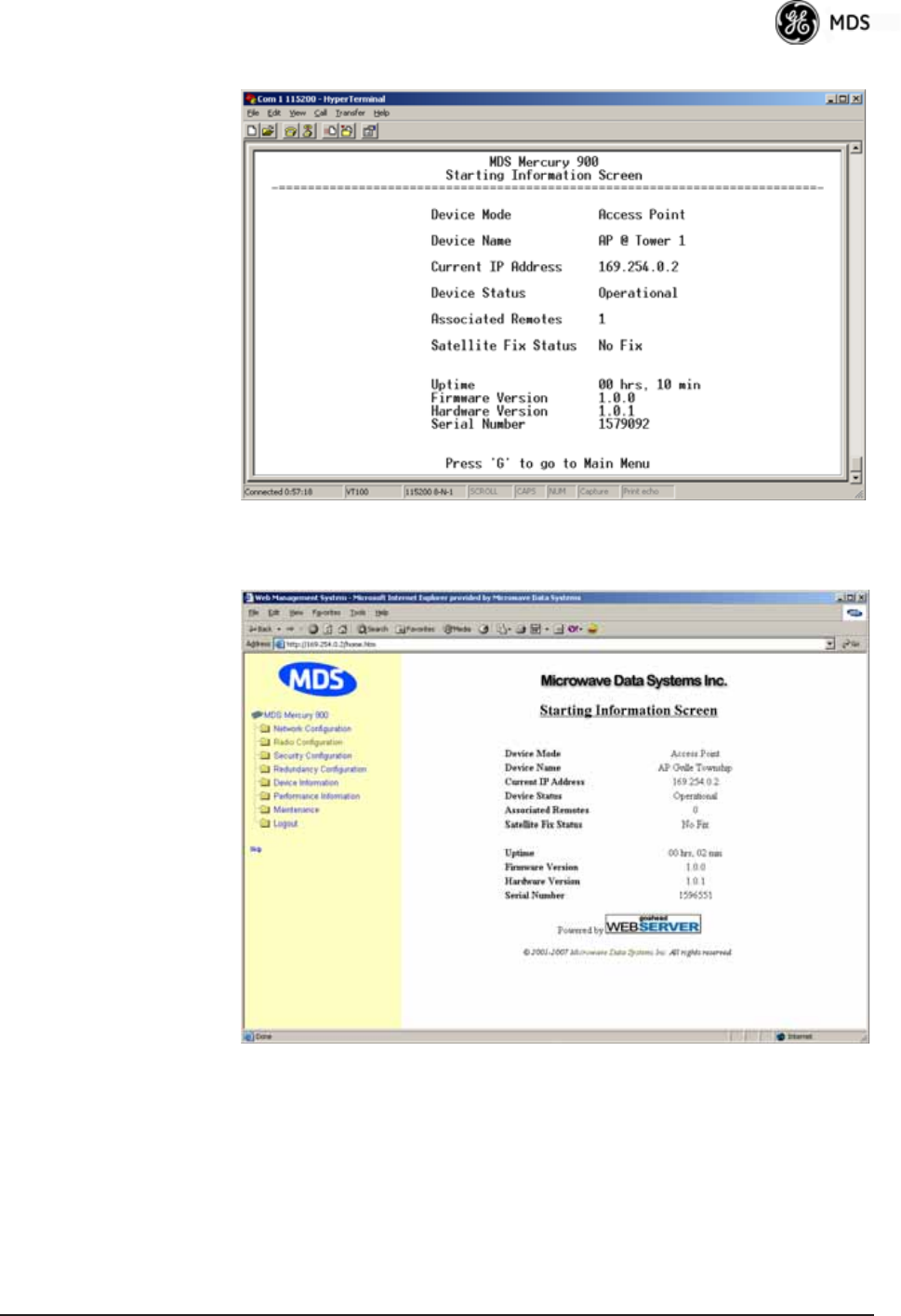
05-4446A01, Rev. E Mercury Reference Manual 35
Figure 3-2. View of MS with a text-based program
(Console Terminal shownTelnet has similar appearance)
Invisible place holder
Figure 3-3. View of the MS with a Browser
(Selections at left provide links to the various menus)
3.2 ACCESSING THE MENU SYSTEM
The radio has no external controls or adjustments. All configuration,
diagnostics, and control is performed electronically using a connected
PC. This section explains how to connect a PC, log into the unit, and
gain access to the built-in menus.

36 Mercury Reference Manual 05-4446A01, Rev. E
3.2.1 Methods of Control
Access the unit’s configuration menus in one of several ways:
•Local Console—This is the primary method used for the exam-
ples in this manual. Connect a PC directly to the COM1 port
using a serial communications cable and launch a terminal com-
munications program such as HyperTerminal (found on most
PCs by selecting Start>>Programs>>Accessories>>Communica-
tions>>HyperTerminal). This method provides text-based access to
the unit’s menu screens. Console control is a hardware-based
technique, and is intended for local use only (maximum recom-
mended cable length of 50 ft./15 m).
•Telnet or SSH*—Connect a PC to the unit’s LAN port, either
directly or via a network, and launch a Telnet session. This
method provides text-based access to the unit’s menu screens in
a manner similar to a Local Console session. You can run Telnet
sessions locally or remotely through an IP connection.
•Web Browser*—Connect a PC to the unit’s LAN port, either
directly or via a network, and launch a web browser session (for
example, Internet Explorer, Firefox, etc.). Enter the IP address
of the device to be managed into the browser’s address field.
This method provides a graphical representation of each screen,
just as you would see when viewing an Internet web site. The
appearance of menu screens differs slightly from other methods
of control, but the content and organization of screen items is
similar. Web browser sessions may be run locally or remotely
using an IP connection.
* When connecting directly to a radio, a crossover cable is required. When
connecting using a network, switch, or router, a straight-through cable is required.
3.2.2 PC Connection and Log In Procedures
The following steps describe how to access the radio’s menu system.
These steps require a PC to be connected to the unit’s COM1 or LAN port
as shown in Figure 3-4 on Page 37.
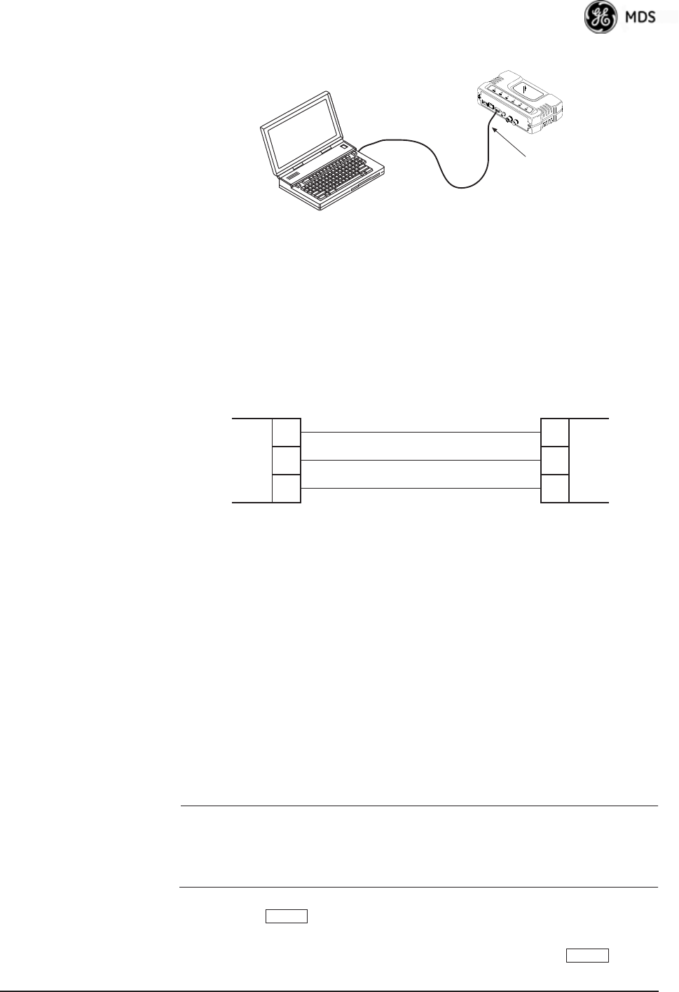
05-4446A01, Rev. E Mercury Reference Manual 37
Invisible place holder
Figure 3-4. PC Configuration Setup
Starting a Local
Console Session
(Recommended for
first-time log-in)
1. Connect a serial communications cable between the PC and the
unit’s COM1 port. If necessary, a cable may be constructed for this
purpose as shown in Figure 3-5.Invisible place holder
Figure 3-5. Serial Communications Cable (DB-9M to DB-9F)
(Maximum Recommended Cable Length 50 feet/15 meters)
2. Launch a terminal emulation program such as HyperTerminal and
configure the program with the following settings:
• 115,200 bps data rate
• 8 data bits, no parity
• One stop bit, and no flow-control
• Use ANSI or VT100 emulation.
TIP: The HyperTerminal communications program can be accessed on
most PCs by selecting this menu sequence: Start>>Programs>>Accesso-
ries>>Communications>>HyperTerminal.
NOTE: If the unit is powered-up or rebooted while connected to a
terminal, you will see a series of pages of text information
relating to the booting of the unit’s processor. Wait for the
log-in screen before proceeding.
3. Press the key to receive the login: prompt.
4. Enter the username (default username is admin). Press .
PC Running Terminal Session
(115,200 bps, 8N1)
To COM1 or LAN Port
(see text)
Transceiver
PC Running Terminal Session
(115,200 bps, 8N1)
Transceiver
To COM1 or LAN Port
(See Text)
3
5
2
3
5
2
TXD
GND
RXD
TXD
GND
RXD
DCE
DB-9 MALE
(TO MDS PRODUCT)
DTE
DB-9 FEMALE
(TO COMPUTER)
ENTER
ENTER
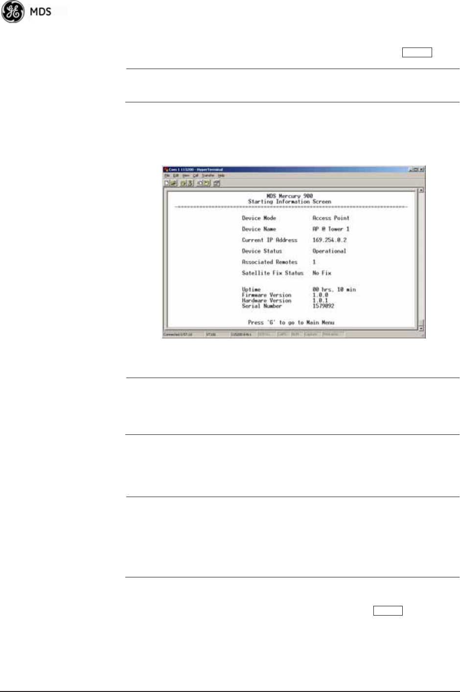
38 Mercury Reference Manual 05-4446A01, Rev. E
5. Enter your password (default password is admin). For security, your
password keystrokes do not appear on the screen. Press .
NOTE: Passwords are case sensitive. Do not use punctuation mark
characters. You may use up to 13 alpha-numeric characters.
The unit responds with the Starting Information Screen (Figure 3-6).
From here, you can review basic information about the unit or press G
to proceed to the Main Menu.
Invisible place holder
Figure 3-6. Starting Information ScreenLocal Console Session
Starting a Telnet
Session NOTE: This method requires that you know the IP address of the unit
beforehand. If you do not know the address, use the Local
Console method (above) and access the Starting Information
Screen. The address is displayed on this screen.
1. Connect a PC to the unit’s LAN port, either directly with a crossover
cable or via a network with a straight-through cable. The LAN LED
lights to indicate an active connection.
NOTE: When using Ethernet to access the unit, you might need to
change your computer’s IP address to be on the same subnet as
the radio. You can identify or verify the unit’s IP address by
using a Local Console session to communicate with the radio
through its COM1 Port and viewing the Starting Information
Screen.
2. Start the Telnet program on your computer, targeting the IP address
of the unit to which you are connected, and press .
ENTER
ENTER

05-4446A01, Rev. E Mercury Reference Manual 39
TIP: You can start a Telnet session on most PCs by selecting: Start>>Pro-
grams>>Accessories>>Command Prompt. At the command prompt
window, type the word telnet, followed by the unit’s IP address
(e.g., telnet 10.1.1.168). Press to receive the Telnet log in
screen.
NOTE: Never connect multiple units to a network with the same IP
address. Address conflicts will result in improper operation.
3. Enter your username (default username is admin). Press .
Next, the Password: prompt appears. Enter your password (default
password is admin). For security, your password keystrokes will not
appear on the screen. Press .
The unit responds with a Starting Information Screen (see
Figure 3-6 on Page 38). From here, you can review basic informa-
tion about the unit or press G to proceed to the Main Menu.
NOTE: Passwords are case sensitive. Do not use punctuation mark
characters. You may use up to 13 alpha-numeric characters.
Starting a Web
Browser Session NOTE: Web access requires that you know the IP address of the unit
you are connecting to. If you do not know the address, start a
Local Console session (see Starting a Local Console Session
(Recommended for first-time log-in) on Page 37) and access
the Starting Information Screen. The IP address is displayed
on this screen.
1. Connect a PC to the unit’s LAN port, either directly or using a
network. If connecting directly, use an Ethernet crossover cable; if
connecting using a network, use a straight-through cable. The LAN
LED lights to indicate an active connection.
2. Launch a Web-browser session on your computer (i.e., Internet
Explorer, Firefox, etc.).
3. Type the unit’s IP address and press .
4. A log-in screen is displayed (Figure 3-7 on Page 40) where you
enter a user name and password to access the unit’s menu system.
Note that the default entries are made in lower case. (Default User
Name: admin; Default Password: admin)
ENTER
ENTER
ENTER
ENTER
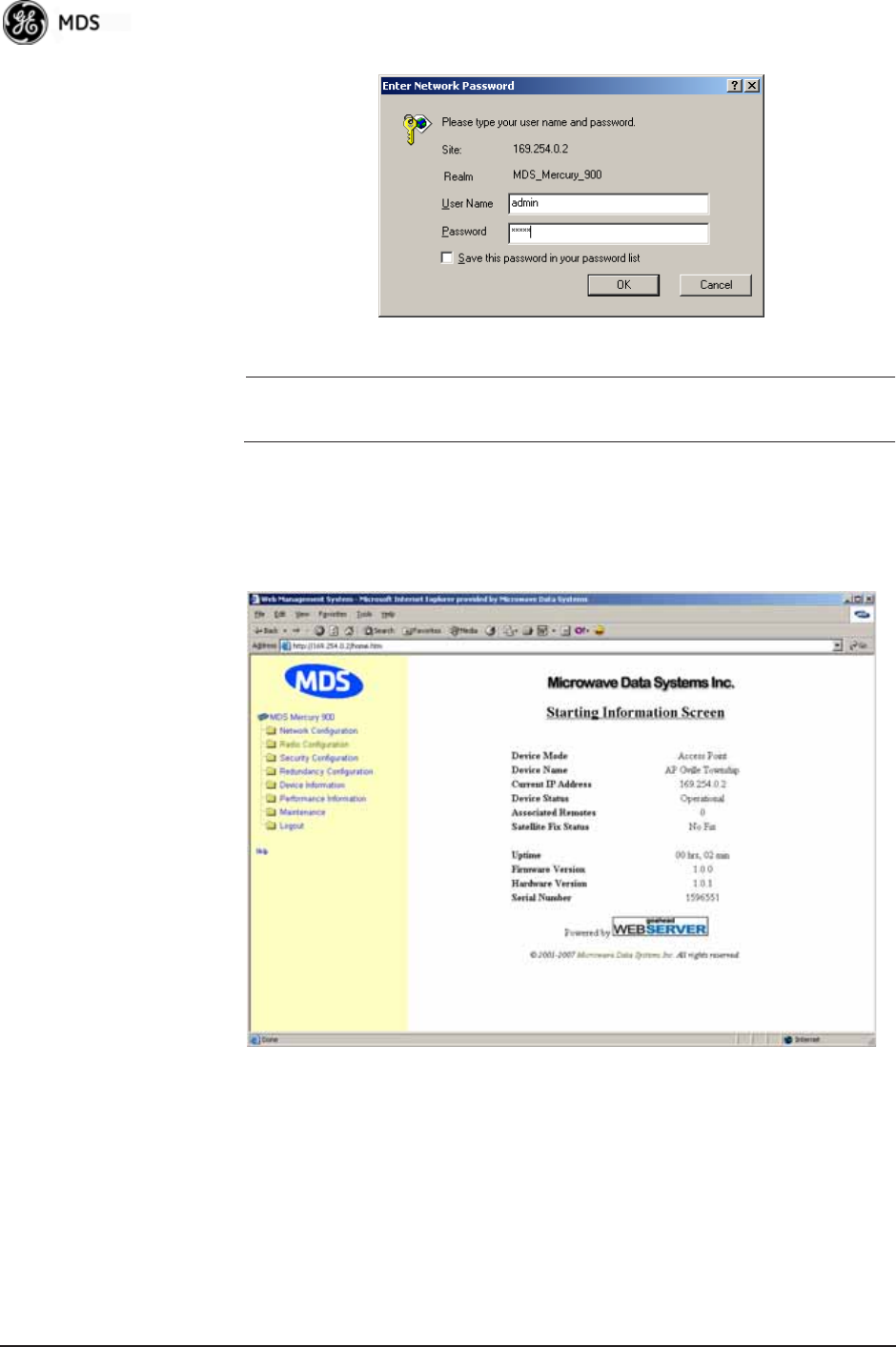
40 Mercury Reference Manual 05-4446A01, Rev. E
Invisible place holder
Figure 3-7. Log-in Screen when using a Web Browser
NOTE: Passwords are case sensitive. Do not use punctuation mark
characters. You may use up to 13 alpha-numeric characters.
5. Click OK. The unit responds with a startup menu screen similar to
that shown in Figure 3-8. From here, you can review basic informa-
tion about the unit or click one of the menu items at the left side of
the screen. Invisible place holder
Figure 3-8. Starting Information ScreenWeb Browser Example
3.2.3 Navigating the Menus
Via Terminal Telnet or SSH Sessions
Recommended for first-time log-in
Local Console, Telnet, and SSH sessions use multi-layered text menu
systems that are nearly identical. To move further down a menu tree,
you type the letter assigned to an item of interest. This takes you to an

05-4446A01, Rev. E Mercury Reference Manual 41
associated screen where settings may be viewed or changed. In most
cases, pressing the key moves the screen back one level in the
menu tree.
In general, the top portion of menu screens show read-only information
(with no user selection letter). The bottom portion of the screen contains
parameters you can select for further information, alteration of values,
or to navigate to other submenus.
NOTE: Early versions of PuTTY might not operate when using SSH
to connect to the transceiver. The latest version (0.60 at the
time of publication) does work with the transceiver’s internal
server. Both the latest released and the latest development
snapshot can be downloaded from:
www.chiark.greenend.org.uk/~sgtatham/putty/.
When you arrive at a screen with user-controllable parameter fields, you
select the menu item by pressing an associated letter on the keyboard. If
there is a user definable value, the field will clear to the right of the menu
item and you can type the value you wish to use. Follow this action by
pressing the key to save the changes. If you make a mistake or
change your mind before pressing the key, simply press
to restore the previous value.
In some cases, when you type a letter to select a parameter, you will see
a prompt at the bottom of the screen that says Choose an Option. In these
screens, press the keyboard’s to step through the available
selections. When the desired option appears, press the key to
choose that selection. In some cases, you can change several parameters
and then save them with a single keystroke. Use the key to
cancel the action and restore the previous values.
Logging Out Via
Terminal Emulator
or Telnet
From the Main Menu screen, press Q to quit and terminate the session.
NOTE: To maintain security, it is best to log-out of the menu system
entirely when you are done working with it. If you do not log
out, the session automatically ends after 10 minutes of inac-
tivity.
Navigating via Web Browser
Navigating with a Web browser is straightforward with a framed “home
page.” The primary navigation menu is permanently located on the
left-hand side of this page. Simply click the desired menu item to make
it active.
Logging Out Via
Web Browser Click Logout in the left-hand frame of the browser window. The
right-hand frame changes to a logout page. Follow the remaining
instructions on this screen.
ESCAPE
ENTER
ENTER ESCAPE
SPACEBAR
ENTER
ESCAPE
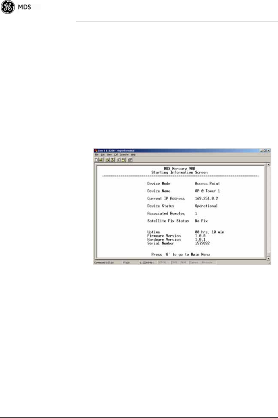
42 Mercury Reference Manual 05-4446A01, Rev. E
NOTE: In the menu descriptions that follow, parameter options/range,
and any default values are displayed at the end of the text
between square brackets. Note that the default setting is
always shown after a semicolon:
[available settings or range; default setting]
3.3 BASIC OVERVIEW OF OPERATION
3.3.1 Starting Information Screen
Once you have logged into the Management System, the Starting Infor-
mation Screen (Figure 3-9) appears with an overview of the transceiver
and its current operating conditions.
Figure 3-9. Starting Information Screen
(AP screen shown; Remote similar, differences noted below)
•Device Mode—Operating mode of the unit as it relates to the
radio network.
•Device Name—This is a user-defined parameter that appears in
the heading of all pages. (To change it, see Network Configura-
tion Menu on Page 45.)
•Current IP Address—Unit’s IP address [169.254.0.2]
•Device Status—Condition of the unit’s operation as follows:
At Access Point:
•Operational—Unit operating normally.
•Initializing—This is the first phase after boot-up.
•Synchronizing—Unit is waiting for the GPS receiver to obtain
a satellite fix and for its internal clock to synchronize to the
GPS timing signals.

05-4446A01, Rev. E Mercury Reference Manual 43
•Alarmed—The unit has detected one or more alarms that have
not been cleared.
At Remote:
•Scanning—The unit is looking for an Access Point beacon
signal.
•Ranging—Unit is adjusting power, timing, and frequency
with an AP.
•Connecting—The unit has found a valid beacon signal for its
network.
•Authenticating—Device is attempting device authentication.
•Associated —The unit has successfully synchronized and
associated with an Access Point.
•Alarmed—The unit is has detected one or more alarms that
have not been cleared.
NOTE: If an alarm is present when this screen is displayed, an “A)”
appears to the left of the Device Status field. Pressing the “A”
key on your keyboard takes you directly to the “Current
Alarms” screen.
•Associated Remotes (AP Only)—Indicates the number of
Remotes that have achieved association with the AP.
•Connection Status (Remote Only)—Indicates whether the
Remote has an RF connection with an AP.
•Satellite Fix Status—Indicates whether internal GPS receiver has
achieved synchronization with GPS satellite signals.
•Uptime—Elapsed time since the transceiver was last booted up.
•Firmware Version—Version of firmware that is currently active in
the unit.
•Hardware Version— Hardware version of the transceiver’s printed
circuit board.
•Serial Number—Make a record of this number. Provide this num-
ber when purchasing Authorization Codes to upgrade unit capa-
bilities in the future. (See “Authorization Codes” on Page 136.)
3.3.2 Main Menu
The Main Menu (Figure 3-10/Figure 3-11) is the entry point for all
user-controllable features. The transceiver’s Device Name appears at the
top of this and all other screens as a reminder of the unit you are cur-
rently controlling.
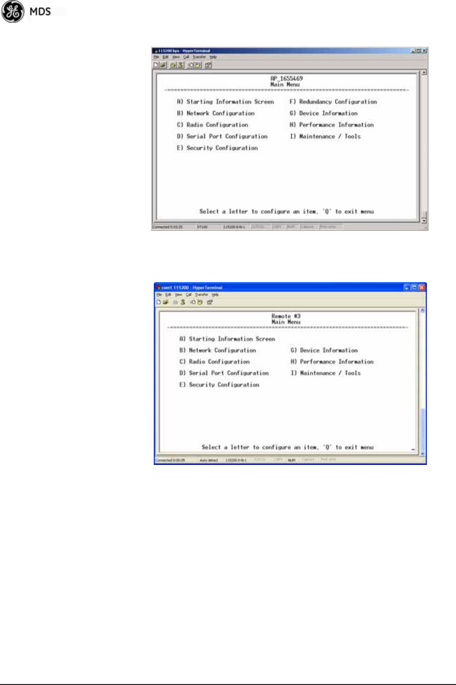
44 Mercury Reference Manual 05-4446A01, Rev. E
Figure 3-10. Main Menu (AP)
(AP menu shown, Remote similar; Differences noted in text below)
Figure 3-11. Main Menu (MDS 3650 Remote Only)
•Starting Information Screen—Select this item to return to the Start-
ing Information screen described above.
•Network Configuration—Tools for configuring the data network
layer of the transceiver. (See “CONFIGURING NETWORK
PARAMETERS” on Page 45)
•Radio Configuration—Tools to configure the wireless (radio)
layer of the transceiver. (See “RADIO CONFIGURATION” on
Page 65)
•Serial Port Configuration—Menus for tailoring the COM1 port for
data mode operation (data only). (See “Serial Port Configura-
tion” on Page 76)
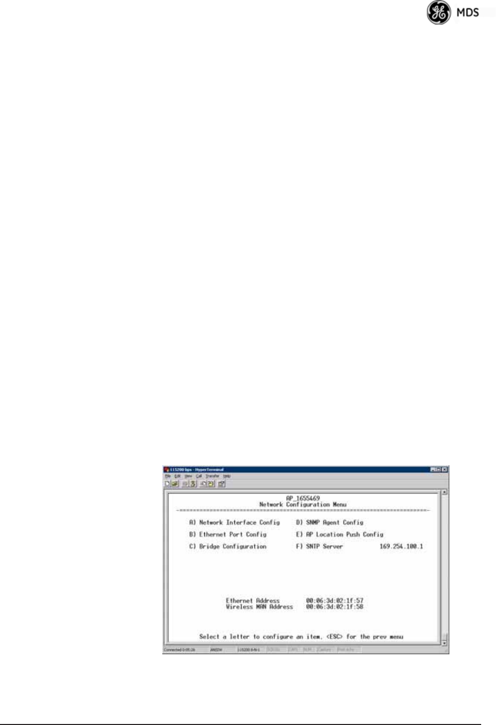
05-4446A01, Rev. E Mercury Reference Manual 45
•Security Configuration—Tools to configure the security services
available with the transceiver’s environment. (See “SECURITY
CONFIGURATION MENU” on Page 92)
•Redundancy Configuration—(AP Only) Allows setting of the cri-
teria for switchover in the event of loss of associated Remotes
or excessive packet receive errors.
•GPS Configuration—(Remote Only; not available on MDS 3650
model) View/set parameters related to GPS streaming location
output. (See “GPS CONFIGURATION (REMOTE ONLY)” on
Page 107)
•Device Information—Top level device fields such as model, serial
number, date/time, etc. (See “DEVICE INFORMATION
MENU” on Page 109)
•Performance Information—Status information relating to the radio
and data layer’s performance in the radio network.
(See “PERFORMANCE INFORMATION MENU” on
Page 110)
•Maintenance/Tools—Tools for upgrading firmware code and test-
ing major unit capabilities. (See “MAINTENANCE/TOOLS
MENU” on Page 123)
3.4 CONFIGURING NETWORK
PARAMETERS
3.4.1 Network Configuration Menu
The Network Configuration Menu is the home of several parameters that
you should review and set as necessary before placing a transceiver into
service.
Figure 3-12. Network Configuration Menu
(Standard radio)

46 Mercury Reference Manual 05-4446A01, Rev. E
Figure 3-13. Network Configuration Menu
(Option Set 1 radio)
•Network Interface Config—Presents a menu where you can view or
set various parameters (VLAN Status, IP Configuration, and
DHCP Server Configuration).
•Ethernet Port Config—Presents a menu for defining the status of
the Ethernet port (enabled or disabled), port follows association,
and Ethernet filtering configuration. Detailed explanations of
this menu are contained in Ethernet Port Configuration Menu on
Page 56.
•Bridge Configuration—View/set options for Ethernet Bridge oper-
ation.
•SNMP Agent Config—View/set SNMP configuration parameters.
See “SNMP Agent Configuration” on Page 58 for more infor-
mation.
•AP Location Info Config—On an AP this submenu allows for con-
figuring an AP to automatically download the AP Locations
File to its associated Remotes. On a Remote this submenu
allows for downloading an AP Locations File. See “AP Loca-
tion Push Config Menu” on Page 60 for additional details.
•802.11 Configuration—Presents a submenu for configuring the
radio’s internal WiFi module to be an Access Point for other
WiFi devices (APs), to connect to a WiFi Access Point at
another location (Station), or to connect directly to another
WiFi device (Ad-Hoc).
•SNTP Server—Address of SNTP server (RFC 2030) from which
the transceiver will automatically get the time-of-day. You can
also manually set the date and time. A Mercury unit tries to get
the time and date from the SNTP server only if an IP address is
configured. It will continue to retry every minute until it suc-
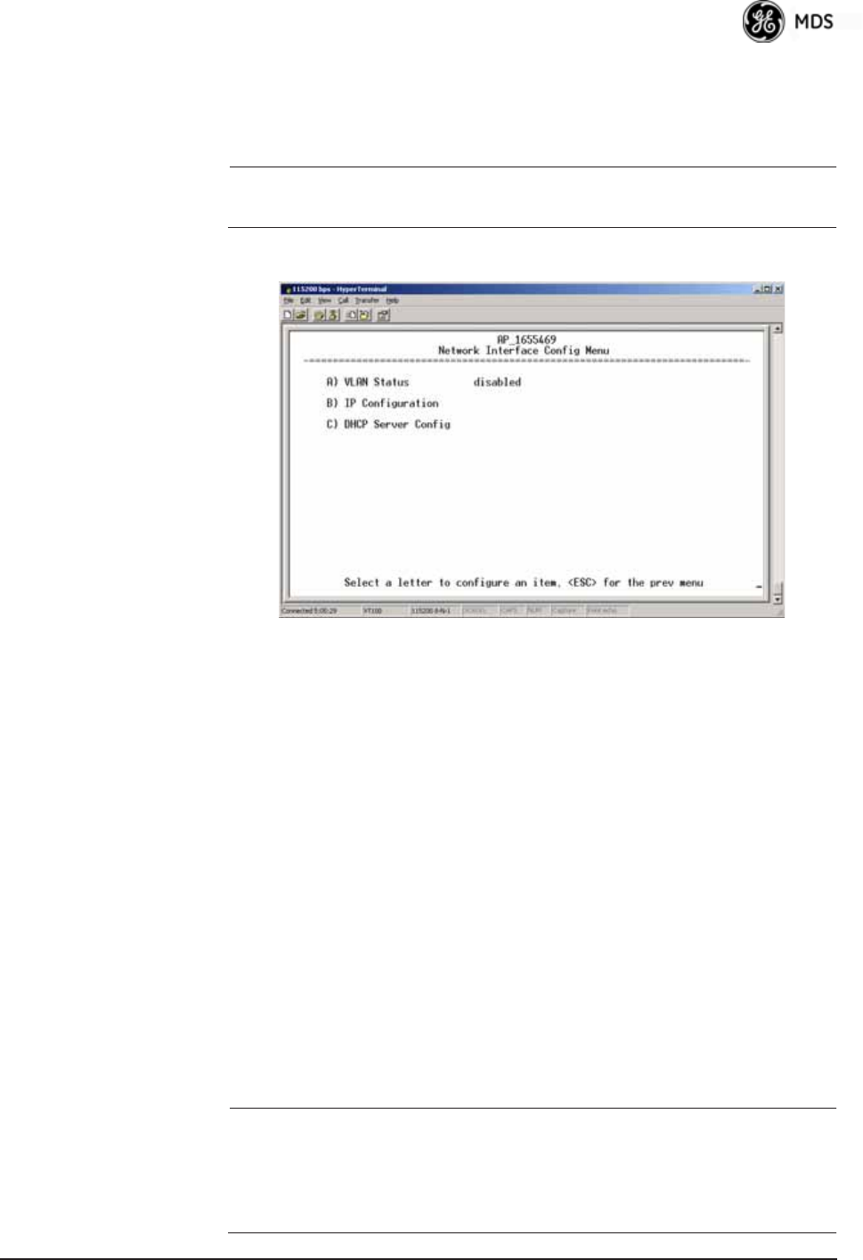
05-4446A01, Rev. E Mercury Reference Manual 47
ceeds.
The transceivers use UTC (Universal Time Coordinated) with a
configurable time offset. [0]
NOTE: The Mercury gets time of day data from the GPS receiver if the
receiver gets a satellite fix.
Network Interface Configuration Submenu
Invisible place holder
Figure 3-14. Network Interface Configuration Submenu
•VLAN Status—This selection is used to enable or disable virtual
LAN operation. For details, refer to VLAN Configuration Menu
on Page 47. [enable, disabled; disabled]
•IP Configuration—This selection presents a submenu for config-
uring the local IP address of the transceiver. Detailed explana-
tions are provided in the section titled IP Configuration Menu
on Page 53.
•DHCP Server Config—Menu for configuration of DHCP services
by the Access Point. DHCP provides “on-the-fly” IP address
assignments to other LAN devices, including Mercury Series
units. For details, refer to DHCP Server Configuration (Data
and Mgmt) on Page 50.
VLAN Configuration Menu
The VLAN Configuration menu (Figure 3-15) becomes active and vis-
ible when you enable VLAN Status on the Network Interface Configura-
tion Menu, and you press the Enter key.
CAUTION:The VLAN Status parameter must be consistent at both the
Access Point and Remote radios in order for data to flow
correctly. Failure to do so might result in data not being trans-
ported correctly even when the radios are in an associated state
and able to communicate over-the-air.
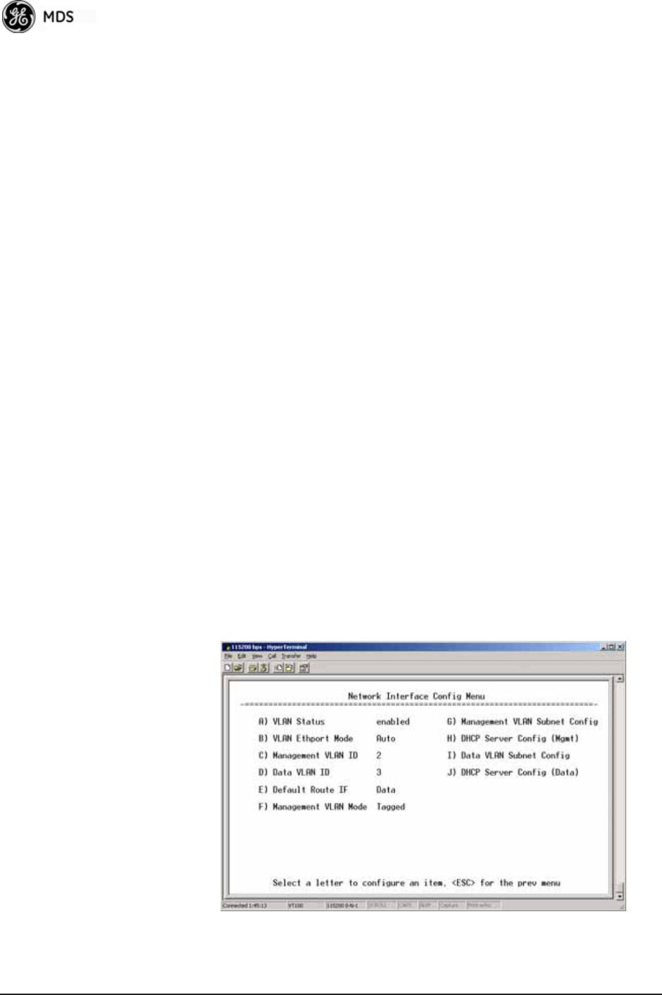
48 Mercury Reference Manual 05-4446A01, Rev. E
About Virtual LAN in
Mercury A VLAN is essentially a limited broadcast domain, meaning that all
members of a VLAN receive broadcast frames sent by members of the
same VLAN but not frames sent by members of a different VLAN. For
more information, refer to the IEEE 802.1Q standard.
The transceiver supports port-based VLAN at the Ethernet interface and
over the air, according to the IEEE 802.1Q standard. When VLAN Status
is enabled, the wireless port of both AP and Remote radios act,
according to user configuration, as either a trunk port or access port.
The Ethernet port of an Access Point radio is normally configured as a
trunk port. This type of port expects incoming frames to have a VLAN ID
tag and sends outgoing frames with a VLAN tag as well.
The Ethernet port of a Mercury radio can be configured as an access port
or as a trunk port.
When the Ethernet port of a Mercury radio is configured as VLAN
Access Port, the radio tags incoming traffic with a VLAN ID, and strips
the tag before sending traffic out. This VLAN is known as the DATA
VLAN. Additionally, a second VLAN is assigned for other traffic that
is terminated at the radio, such as SNMP, TFTP, ICMP, Telnet, and so
on. This is known as the MANAGEMENT VLAN. Traffic directed to
the integrated terminal server that handles the serial ports is assigned to
the DATA VLAN.
When the Ethernet port of a remote radio is configured as a VLAN
trunk, the radio expects all incoming Ethernet frames to be tagged, and
passes all outgoing frames as received from the wireless link, with the
unchanged VLAN tag.
Network Interface Configuration Submenu—VLAN Items
Invisible place holder
Figure 3-15. VLAN Configuration Menu

05-4446A01, Rev. E Mercury Reference Manual 49
•VLAN Status—Defines whether the radio handles Ethernet
frames in “extended” 802.1Q mode or in “normal” mode in the
Ethernet port. If configured with a trunk port, the Mercury
passes all tagged traffic regardless of the VLAN ID. The Mer-
cury only uses the Data VLAN ID parameter when the ETH port is
configured as an Access Port.
[enabled, disabled; disabled]
•VLAN Ethport Mode—Defines if the Ethernet port acts as a trunk
port or as an access port. Auto mode defines the port as a trunk
port in an AP, or an access port in a Remote radio.
[Auto, Trunk, Access; Auto]
•Management VLAN ID—Defines the VLAN ID for traffic directed
to the radio itself, other than the terminal server process. This
VLAN ID is used for filtering and for tagging purposes.
[1-4094; 2]
•Data VLAN ID—Defines the VLAN ID assigned to traffic directed
to and from the Ethernet port and the terminal server process in
the radio. This VLAN ID is used for filtering and tagging pur-
poses. [1-4094; 3]
•Default Route IF—Defines the VLAN that contains the default
gateway in the radio. [MGMT, DATA; MGMT]
•Management VLAN Mode—Applies the VLAN tag to management
frames. [Tagged, Native; Tagged].
•Management VLAN Subnet Config—Presents a screen where you
can set the IP Address Mode, Static IP Address, and Static IP
Netmask (see Figure 3-16 on Page 50).
•DHCP Server Config (Mgmt)—Presents a screen where you can
view or set the DHCP server status and address information for
management functions (see Figure 3-17 on Page 51).
•Data VLAN Subnet Config—Presents a screen where you can view
or set the IP mode and address information (see Figure 3-19 on
Page 52).
•DHCP Server Config (Data)—Presents a screen where you can view
or set DHCP server status and address information for data
functions (see Figure 3-18 on Page 52).
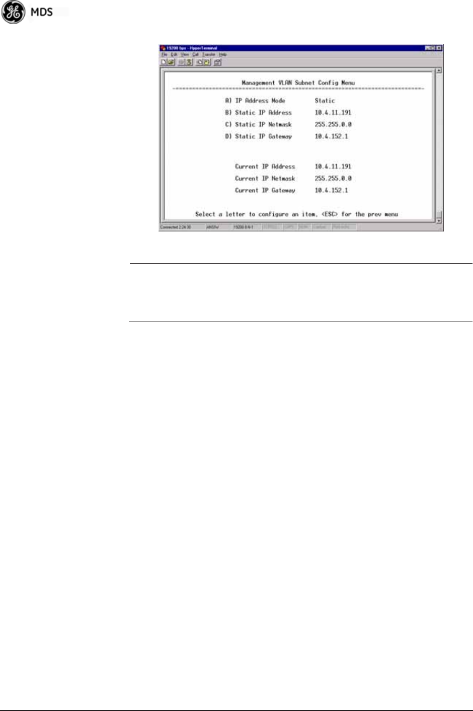
50 Mercury Reference Manual 05-4446A01, Rev. E
Management VLAN
Subnet
Configuration Menu
Invisible place holder
Figure 3-16. Management VLAN Subnet Configuration Menu
NOTE: Changes to any of the following parameters while communi-
cating over the network (LAN or over-the-air) might cause a
loss of communication with the unit you are configuring. You
must re-establish communication using the new IP address.
•IP Address Mode—Defines the source of the IP address of this
device. Only static IP addressing mode is available when VLAN
Status is enabled. [Static, Dynamic; Static]
•Static IP Address—The IPv4 local IP address. [192.168.1.1]
•Static IP Netmask—The IPv4 local subnet mask. This value is
used when the radio attempts to send a locally initiated message,
either from the terminal server, or from a management process.
[255.255.0.0]
The lower three lines of the screen (Current IP Address, Current IP Netmask,
Current IP Gateway) show the current addressing configured at the trans-
ceiver. Current IP Gateway only displays on this screen if Default Route IF
on the Network Interface Config menu (Figure 3-15 on Page 48) is set to
Management.
Selecting option I from the menu in Figure 3-15 on Page 48 displays the
screen shown in Figure 3-19 on Page 52. Note that the IP address is dif-
ferent even though it is the same physical unit. This is because this IP
address is defined for a different VLAN.
DHCP Server
Configuration
(Data and Mgmt)
A transceiver can provide automatic IP address assignments to other IP
devices in the network by providing DHCP (Dynamic Host Configura-
tion Protocol) services. This service eliminates setting an individual
device IP address on Remotes in the network, but it requires some plan-
ning of the IP address range. One drawback to network-wide automatic
IP address assignments is that SNMP services might become inacces-
sible as they are dependent on fixed IP addresses.
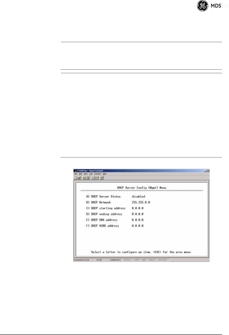
05-4446A01, Rev. E Mercury Reference Manual 51
You can make a network of radios with the DHCP-provided IP address
enabled or with DHCP services disabled. In this way, you can accom-
modate locations for which a fixed IP address is desired.
NOTE: There should be only one active DHCP server in a network. If
more than one DHCP server exists, network devices might
randomly get their IP address from different servers every time
they request one.
NOTE: Combining DHCP and IEEE 802.1x device authentication
might result in a non-working radio if the DHCP server is
located at a Remote radio site. If possible, place the DHCP
server at the AP location.
A DHCP server can be run at a Remote, but it is not recom-
mended if 802.1x Device Authentication is in use and if the AP
gets its IP address from the DHCP server on the Remote. In
this case, the Remote cannot authenticate to allow the AP to
get its address, because the AP needs an address to perform
802.1x device authentication. This results in an unsolvable
condition where the AP needs to get an IP address from DHCP
at the Remote, but it can’t get the address until it is authenti-
cated.
Invisible place holder
Figure 3-17. DHCP Server Configuration (Mgmt) Menu
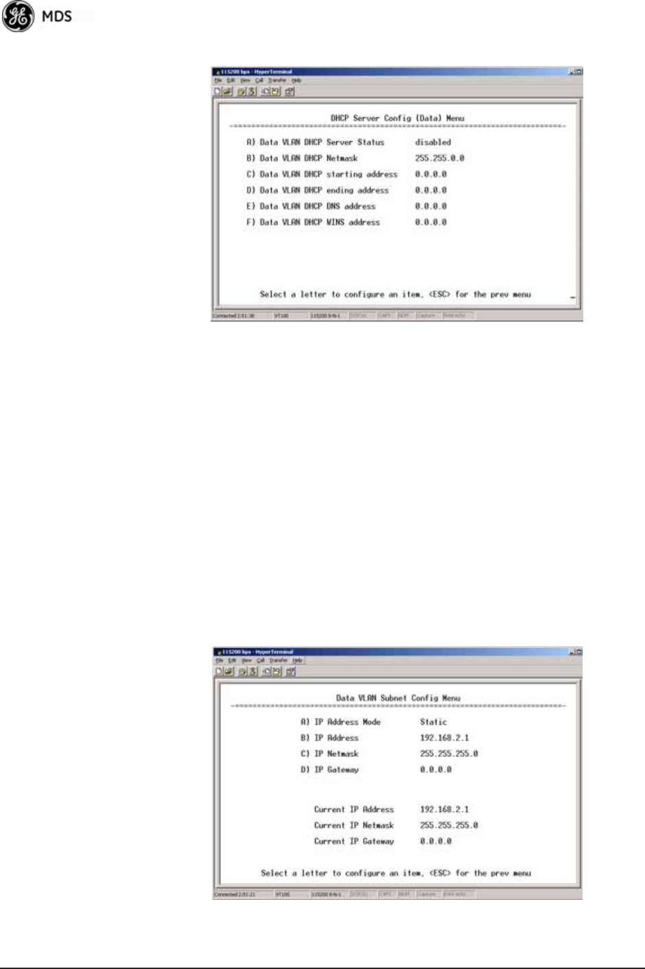
52 Mercury Reference Manual 05-4446A01, Rev. E
Invisible place holder
Figure 3-18. DHCP Server Configuration (Data) Menu
•DHCP Server Status—Enable/Disable the response to DHCP
requests to assign an IP address. [Disabled/Enabled; Disabled]
•DHCP Netmask—IP netmask to be assigned along with the IP
address in response to a DHCP request. [0.0.0.0]
•DHCP starting address—Lowest IP address in the range of
addresses provided by this device. [0.0.0.0]
•DHCP ending address—Highest IP address in the range of
addresses provided by this device. A maximum of 256
addresses is allowed in this range. [0.0.0.0]
•DHCP DNS address—Domain Name Server address provided by
this service.
•DHCP WINS address—Windows Internet Naming Service server
address provided by this service.
Data VLAN Subnet
Configuration Menu Invisible place holder
Figure 3-19. Data VLAN Subnet Configuration Menu
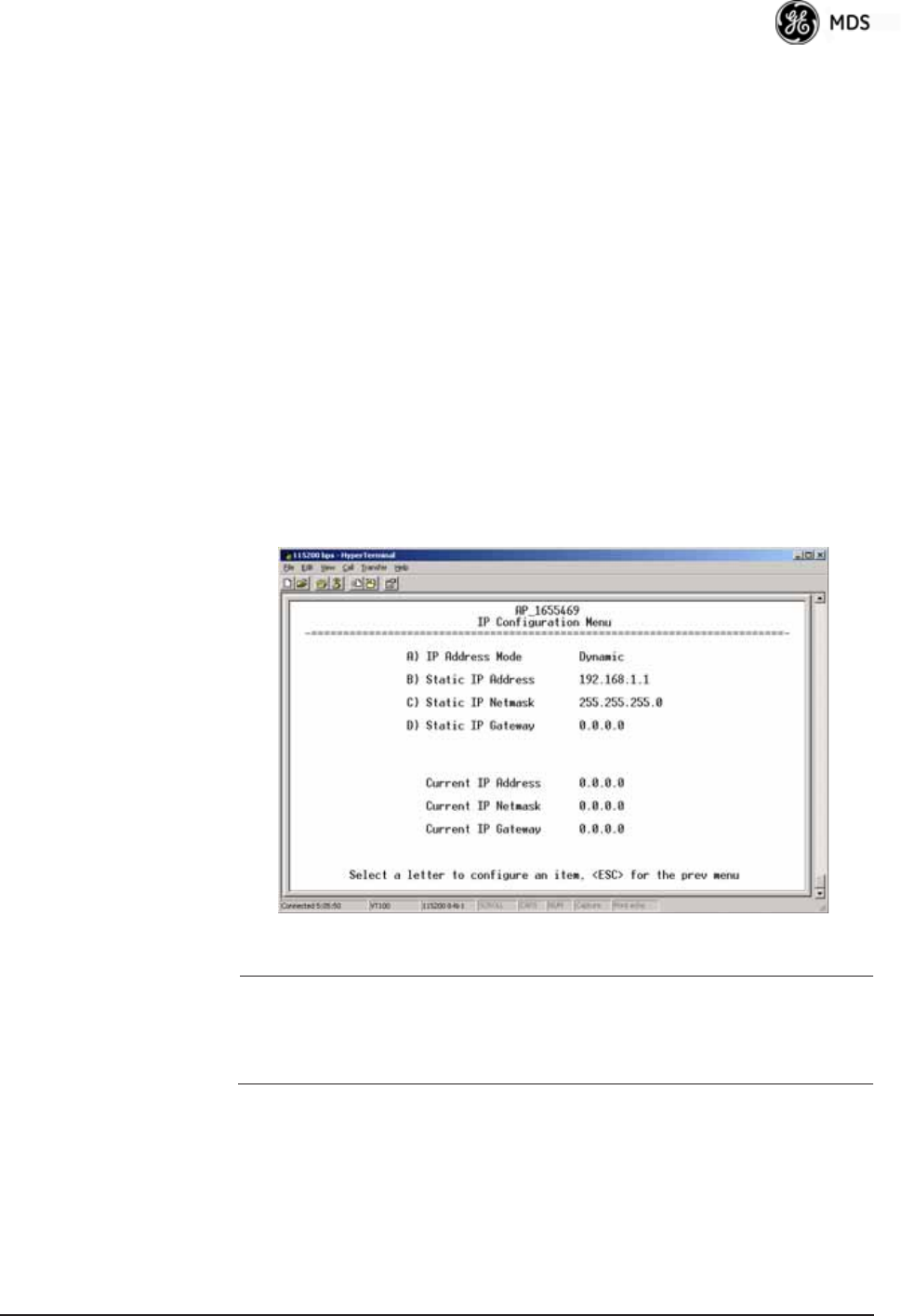
05-4446A01, Rev. E Mercury Reference Manual 53
•IP Address Mode—Defines the source of this device’s IP address.
Only static IP addressing mode is available when VLAN Status
is enabled [Static; Static]
•IP Address—The IPv4 local IP address. [192.168.1.1]
•IP Netmask—The IPv4 local subnet mask. This value is used
when the radio attempts to send a locally initiated message,
from either the terminal server or the management process.
[255.255.0.0]
•IP Gateway—The IPv4 address of the default gateway device,
typically a router. [0.0.0.0]
The lower three lines of the screen (Current IP Address, Current IP Netmask,
and Current IP Gateway) show the current addressing configured at the
transceiver. Current IP Gateway only displays on this screen if Default Route
IF on the Network Interface Config menu (Figure 3-15 on Page 48) is set to
Data.
Invisible place holder
IP Configuration Menu
Figure 3-20. IP Configuration Menu
CAUTION: Changes to the following parameters while communicating
over the network (LAN or over-the-air) might cause a loss of
communication with the unit being configured. You must
re-establish communication using the new IP address.
•IP Address Mode—Defines the source of this device’s IP address.
[Static, Dynamic; Static]
•Static IP Address (User Review Recommended)—Essential for con-
nectivity to the transceiver’s MS using the LAN port. Enter any
valid IP address that is unique within the network. This field is
unnecessary if DHCP is enabled. [192.168.1.1]
•Static IP Netmask—The IPv4 local subnet mask. This field is
unnecessary if DHCP is enabled. [255.255.0.0]
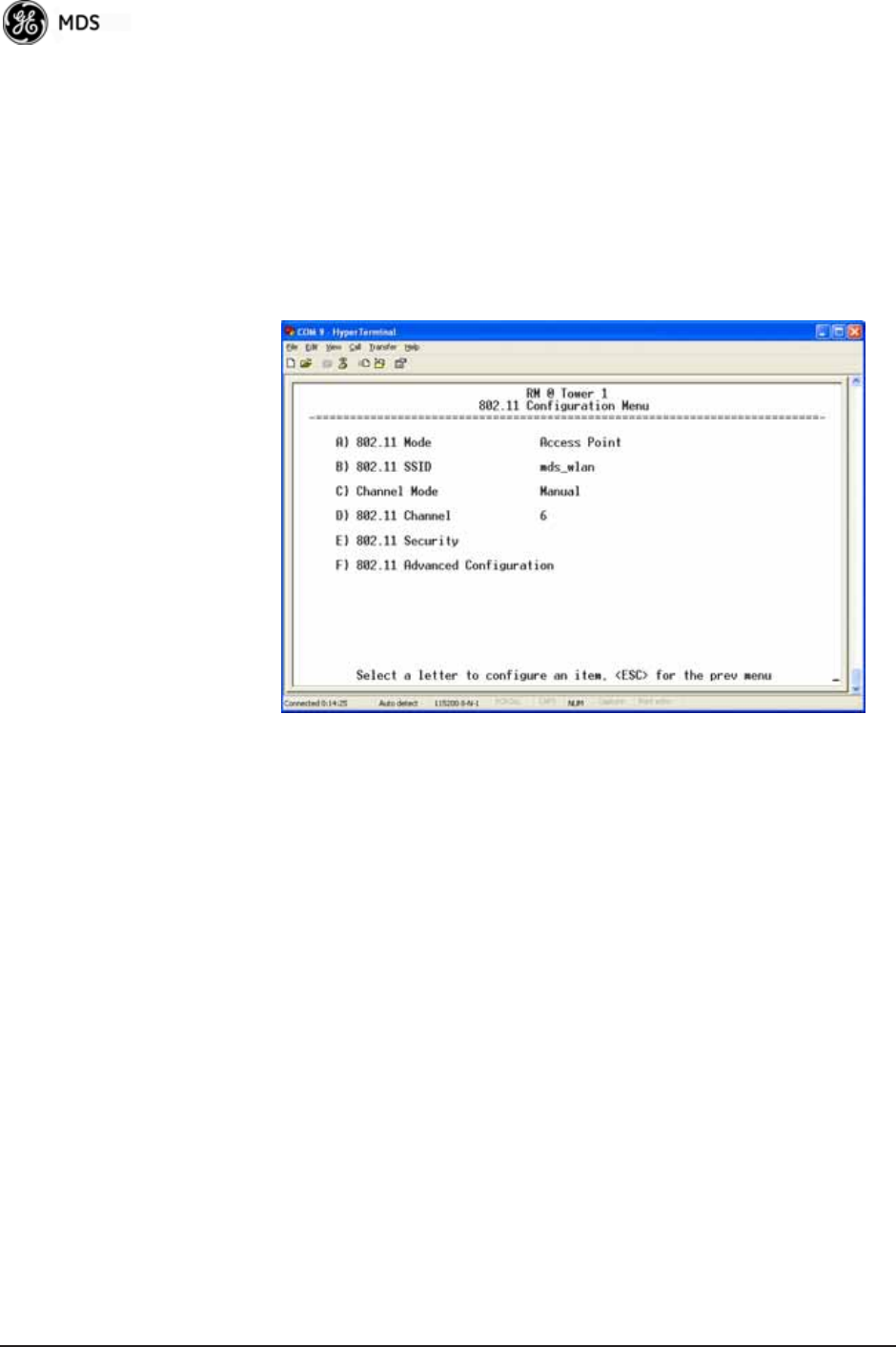
54 Mercury Reference Manual 05-4446A01, Rev. E
•Static IP Gateway—The IPv4 address of the network gateway
device, typically a router. This field is unnecessary if DHCP is
enabled. [0.0.0.0]
The lower three items on the screen (Current IP Address, Net-
mask and Gateway) show the actual addressing at the trans-
ceiver whether it was obtained from static configuration or from
a DHCP server.
802.11 Configuration Submenu Invisible place holder
Figure 3-21. 802.11 Configuration Submenu
•802.11 Mode—Configures the WiFi radio to be an Access Point
for other WiFi devices (Access Point), to connect to a WiFi
Access Point at another location (Station), to connect directly to
another WiFi device (Ad-Hoc), or to be disabled (disabled). The
default setting is disabled.
•802.11 SSID—Service Set Identifier, the name of the wireless
LAN to which to connect. This is equivalent to Network Name
in GE MDS terminology.
•802.11 Channel—(Applies only when 802.11 Mode is set to Access
Point) Sets the 802.11 channel the device will use. This can only
be set to Auto when in Station mode.
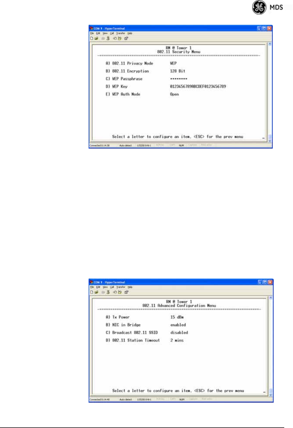
05-4446A01, Rev. E Mercury Reference Manual 55
Invisible place holder
Figure 3-22. 802.11 Security Menu
•802.11 Privacy Mode—Determines which privacy mode is used.
[None, WEP; None]
•802.11 Encryption—Determines the strength of the WEP encryp-
tion. [64 Bit, 128 Bit; 128 Bit]
•WEP Passphrase—A user-entered combination of characters that
is used to generate a WEP Key.
•WEP Key—A security code that is generated using the Wireless
Equivalency Protocol. It is generated by the entry of a WEP
Passphrase (see above) This key should be entered in hexadec-
imal format preceded by 0x. The key should be 13 or 26 hexa-
decimal characters. For example, 1a2b3c4d5e6f709a8b7c6d5e4f.
•WEP Auth Mode—Determines the authentication mode used by
the radio [None, Open, Shared Key, Open and Shared; None]
Invisible place holder
Figure 3-23. 802.11 Advanced Configuration Menu
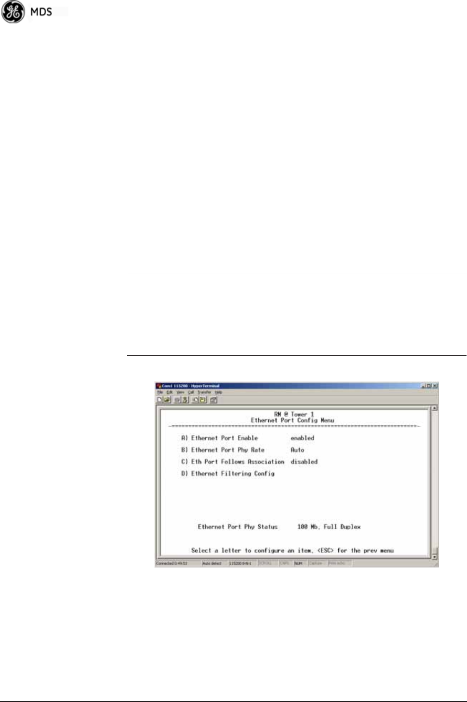
56 Mercury Reference Manual 05-4446A01, Rev. E
•TX Power—Transmit power of the WiFi radio. [1 to 18; 15]
•NIC in Bridge—When enabled, the WiFi interface is added to the
Network Interface Card bridge, allowing traffic to pass between
the WiFi and the other interfaces (LAN and wireless).
[enabled, disabled; enabled]
•Broadcast 802.11 SSID—When enabled, the SSID of the WiFi
Access Point is broadcast over the air so that stations will detect
the AP’s presence. [enabled, disabled; enabled]
•802.11 Station Timeout—Determines how quickly inactive sta-
tions are “aged out” of he WiFi Access Point’s database.
[1 to 240 mins; 2 mins]
3.4.2 Ethernet Port Configuration Menu
The transceiver allows for special control of the Ethernet interface, to
allow traffic awareness and availability of the backhaul network for
redundancy purposes.
NOTE: The transceiver’s network port supports 10BaseT and
100BaseT connections. Confirm that your hub/switch is
capable of auto-switching data rates.
To prevent excessive Ethernet traffic from degrading perfor-
mance, place the transceiver in a segment, or behind routers.
Invisible place holder
Figure 3-24. Ethernet Port Configuration Menu
•Ethernet Port Enable—Allows enabling/disabling Ethernet traffic
for security purposes. Setting it to enabled enables the port.
[enabled, disabled; enabled]
•Ethernet Port Phy Rate—The Ethernet port’s configured speed.
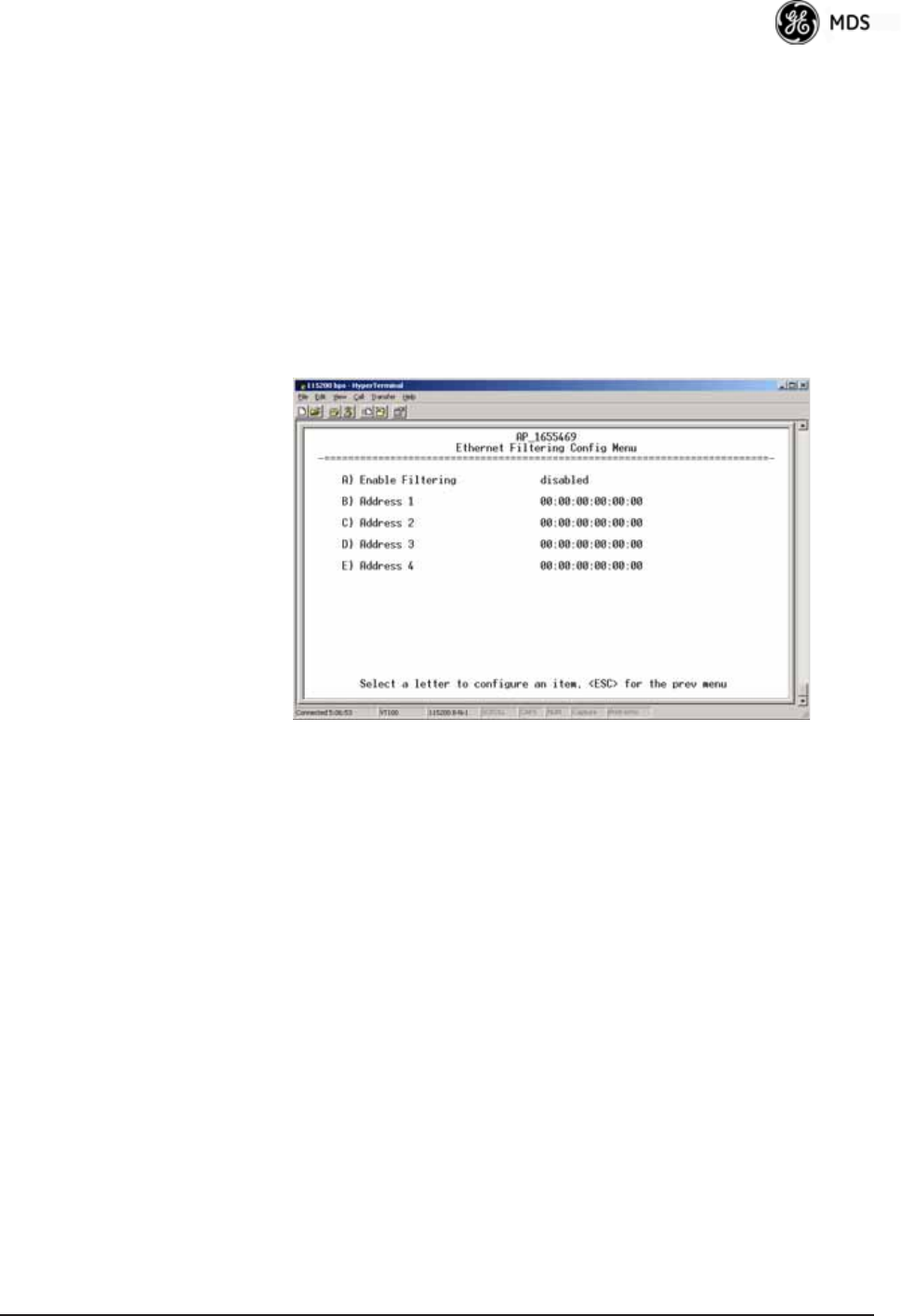
05-4446A01, Rev. E Mercury Reference Manual 57
•Eth Port Follows Association (Remote Only)—When enabled, the
Ethernet port is disabled until the Remote associates. This
allows a PC or laptop connected to the Remote to know when
the wireless link is available. This feature helps middleware on
the laptop in making connectivity decisions. In addition, if the
Remote moves between Access Points on different subnets,
then the laptop can DHCP for a new address when the link
comes back up. [enabled, disabled; disabled]
•Ethernet Filtering Config—Allows enabling/disabling filtering and
specifying of Ethernet addresses.
Ethernet Filtering Configuration Menu
Invisible place holder
Figure 3-25. Ethernet Filtering Configuration Menu
•Enable Filtering—Activates Ethernet filtering.
[enabled, disabled; disabled]
•Address 1, 2, 3, 4—Ethernet address fields. When filtering is
enabled, the Mercury only accepts traffic on its Ethernet port
from the configured addresses.
[Valid MAC address string]
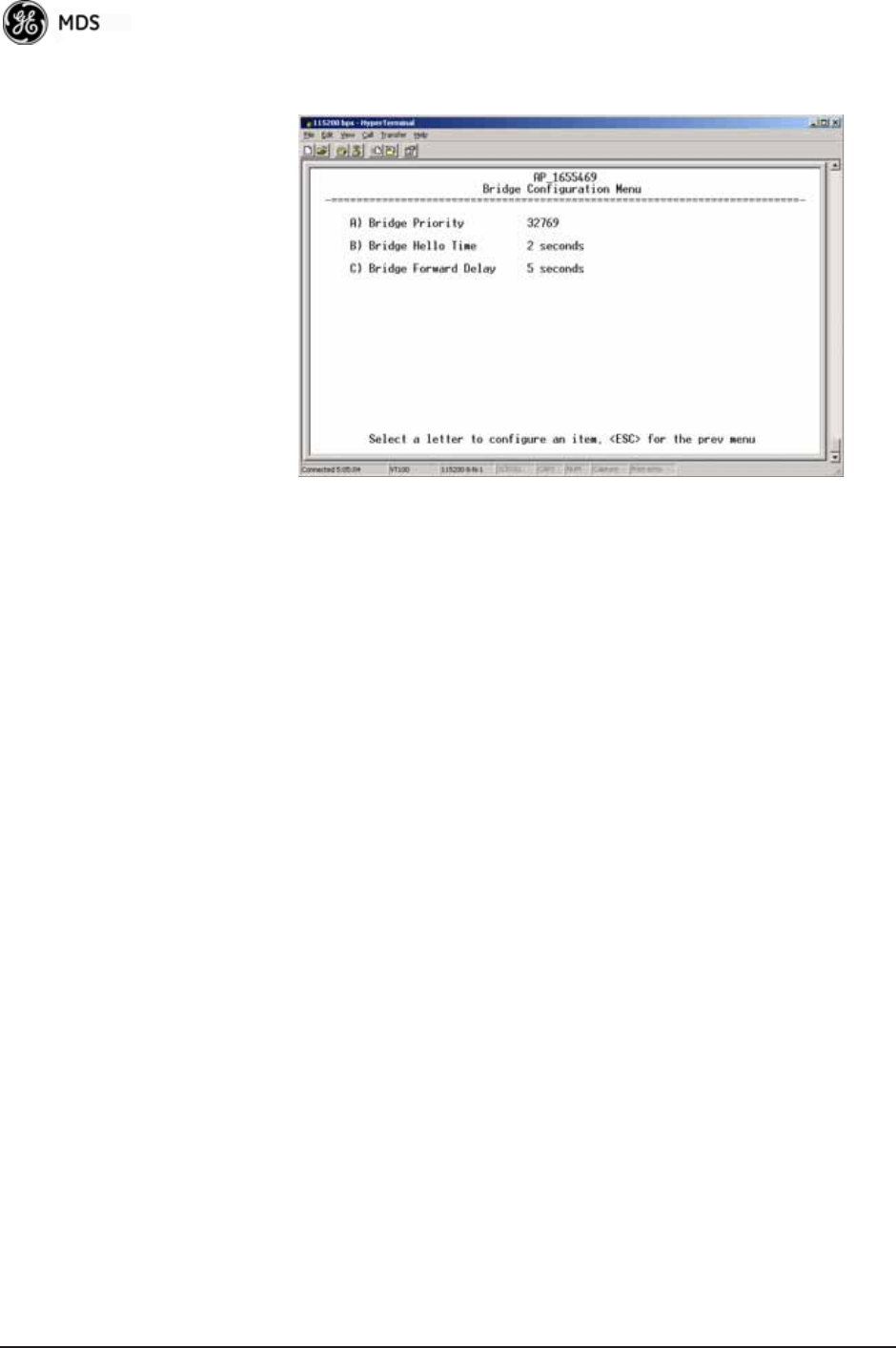
58 Mercury Reference Manual 05-4446A01, Rev. E
3.4.3 Bridge Configuration Invisible place holder
Figure 3-26. Bridge Configuration Menu
•Bridge Priority—View/set the priority of the bridge in the span-
ning tree. [0-65535; 32769]
•Bridge Hello Time—View/set spanning tree hello time. This
parameter affects how often the bridge sends a spanning tree
Bridge Protocol Data Unit (BPDU). [1-10 seconds; 2 seconds]
•Bridge Forward Delay—View/set spanning tree forwarding delay.
Affects how long the bridge spends listening and learning after
initialization. [4-30 seconds; 5 seconds].
3.4.4 SNMP Agent Configuration
The transceiver contains over 100 custom SNMP-manageable objects as
well as the IETF standard RFC1213 for protocol statistics, also known
as MIB II. You can use off-the-shelf SNMP managers to access the
transceiver’s SNMP Agent’s MIB, such as Castle Rock Computing
SNMPc™ and Hewlett Packard OpenView™. The transceiver’s SNMP
agent supports SNMPv1, v2, and v3.
The objects are split into nine MIB files for use with your SNMP man-
ager. There are textual conventions, common files, and specific files.
This allows the flexibility to change areas of the MIB and not affect
other existing installations or customers.
•msdreg.mib—MDS sub-tree registrations
•mds_comm.mib—MDS Common MIB definitions for objects
and events common to the entire product family
•mercury_reg.mib—MDS sub-tree registrations
•mercurytrv1.mib—SNMPv1 enterprise-specific traps
•mercurytrv2.mib—SNMPv2 enterprise-specific traps
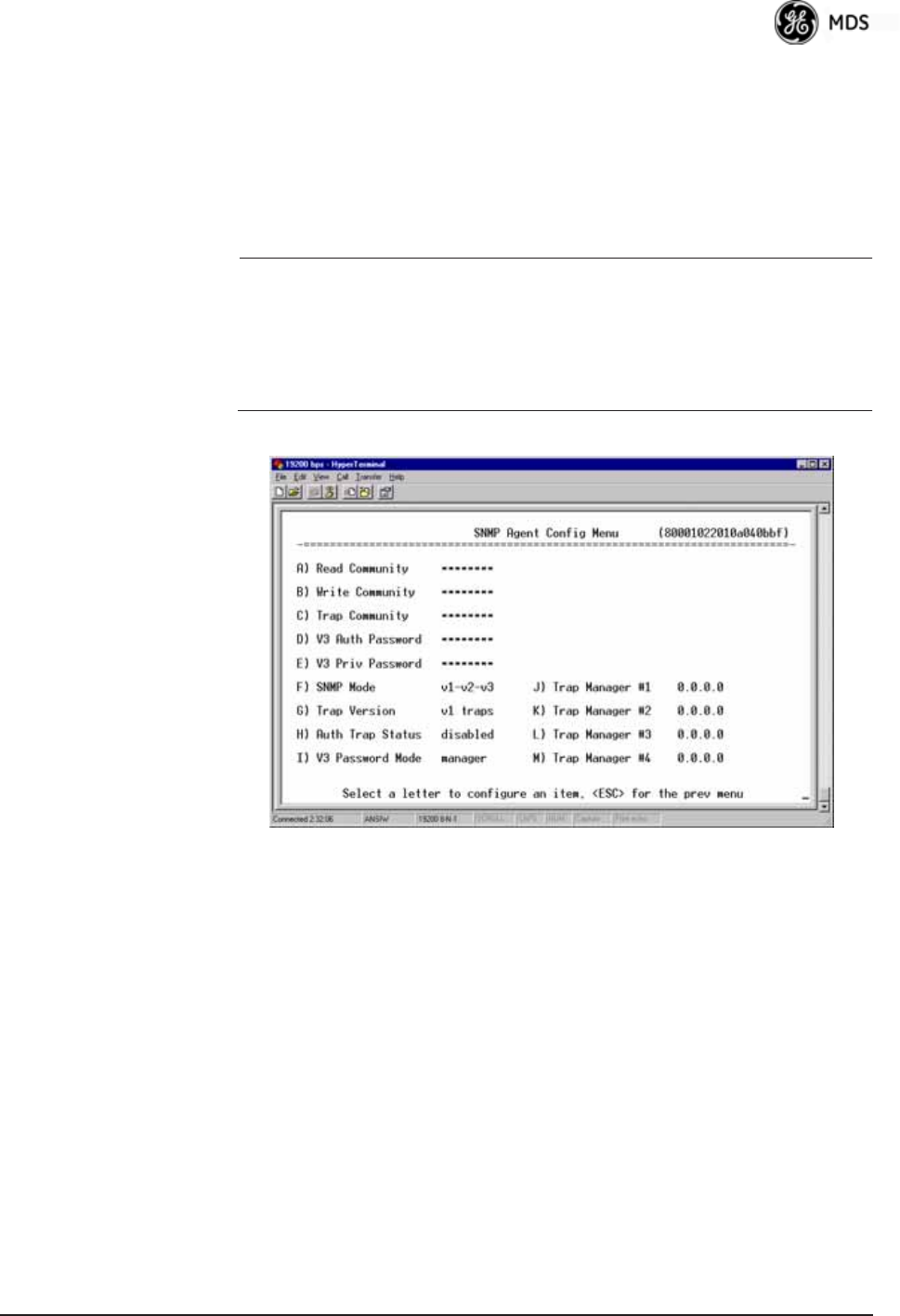
05-4446A01, Rev. E Mercury Reference Manual 59
•mercury_comm.mib— MIB definitions for objects and events
common to the entire Mercury Series
•mercury_ap.mib—MIB definitions for objects and events for an
Access Point transceiver
•mercury_rem.mib—Definitions for objects and events for a
Remote radio
•mercury_sec.mib—For security management of the radio system
NOTE: SNMP management requires that the proper IP address,
network, and gateway addresses are configured in each associ-
ated network transceiver.
In addition, some management systems might require that you
compile the MIB files in the order shown above.
Invisible place holder
Figure 3-27. SNMP Server Configuration Menu
This menu provides configuration and control of vital SNMP functions.
•Read Community String—SNMP community name with
SNMPv1/SNMPv2c read access. This string can contain up to
30 alpha-numeric characters.
•Write Community String—SNMP community name with
SNMPv1/SNMPv2c write access. This string can contain up to
30 alpha-numeric characters.
•Trap Community String—SNMP community name with
SNMPv1/SNMPv2c trap access. This string can contain up to
30 alpha-numeric characters.

60 Mercury Reference Manual 05-4446A01, Rev. E
•V3 Authentication Password—Authentication password stored in
flash memory. This is used when the Agent is managing pass-
words locally (or initially for all cases on reboot). This is the
SNMPv3 password used for Authentication (currently, only
MD5 is supported). This string can contain up to 30
alpha-numeric characters.
•V3 Privacy Password—Privacy password stored in flash memory.
Used when the SNMP Agent is managing passwords locally (or
initially for all cases on reboot). This is the SNMPv3 password
used for privacy (DES encryption). This string can contain
between 8 and 30 alpha-numeric characters.
•SNMP Mode—This specifies the mode of operation of the radio’s
SNMP Agent. The choices are: disabled, v1_only, v2_only,
v3_only, v1-v2, and v1-v2-v3. If the mode is disabled, the Agent
does not respond to any SNMP traffic. If the mode is v1_only,
v2_only, or v3_only, the Agent responds only to that version of
SNMP traffic. If the mode is v1-v2 or v1-v2-v3, the Agent
responds to the specified version of SNMP traffic. [v1-v2-v3]
•Trap Version—This specifies which version of SNMP is used to
encode the outgoing traps. The choices are v1_traps, v2_traps,
and v3_traps. When v3_traps is selected, v2-style traps are sent,
but with a v3 header. [v1_traps, v2_traps, v3_traps]
•Auth Traps Status—Indicates whether or not traps are generated
for failed authentication of an SNMP PDU. [Disabled/Enabled;
Disabled]
•SNMP V3 Passwords—Determines whether v3 passwords are
managed locally or via an SNMP Manager. The different behav-
iors of the Agent, depending on the mode selected, are described
in SNMP Mode above.
•Trap Manager #1—#4— Table of up to four locations on the net-
work to which traps are sent. [Any standard IP address]
NOTE: The number in the upper right-hand corner of the screen is the
SNMP Agent’s SNMPv3 Engine ID. Some SNMP Managers
may need to know this ID in order interface with the trans-
ceiver’s SNMP Agent. The ID only appears on the screen
when SNMP Mode is either v1-v2-v3 or v3_only.
NOTE: For more SNMP information, see “NOTES ON SNMP” on
Page 180.
3.4.5 AP Location Push Config Menu
This menu configures the AP for updating connected remotes with the
AP Locations File loaded on the AP.
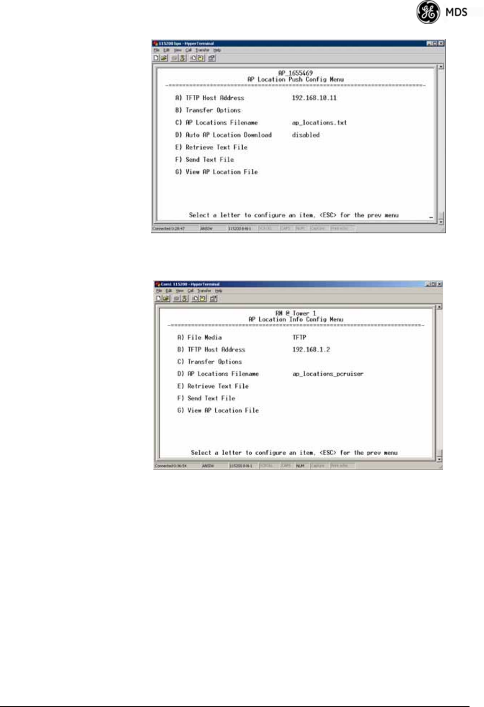
05-4446A01, Rev. E Mercury Reference Manual 61
Invisible place holder
Figure 3-28. AP Location Push Config Menu
Invisible place holder
Figure 3-29. AP Location Info Configuration Menu, TFTP Mode

62 Mercury Reference Manual 05-4446A01, Rev. E
Invisible place holder
Figure 3-30. AP Location Info Configuration Menu, USB Mode
(Option Set 1 Remote only)
•File Media—A selection of methods for transferring files to and
from the radio available on firmware version 3.0 radios. The
options are: TFTP and USB.
•TFTP Host Address—IP address of the TFTP server that holds the
AP locations file. [any valid IP address; 0.0.0.0]
•Transfer Options—Menu for configuring the TFTP transfer.
•AP Locations Filename—Name of the AP Locations file on the
server. [any valid filename string; ap_locations.txt]
•Auto AP Location Download—A setting to force connected remotes
to download immediately the AP Locations file on the AP.
Remotes that associate to an AP with this feature will also
download the file.
•Retrieve Text File—Download AP Locations text file from the
server.
•Send Text File—Upload the local AP Locations file to the server.
•View AP Location File—Allows on-screen review of the AP Loca-
tions file. An example screen is shown in Figure 3-31.

05-4446A01, Rev. E Mercury Reference Manual 63
Invisible place holder
Figure 3-31. AP Location Text File
AP Locations File Syntax and Guidelines
The AP Locations file is used by the Remote radio to determine which
Access Point to connect to when operating in Hopping w/ Hand-offs mode.
The AP Locations file is a simple text file containing information about
the location and configuration of all Access Points that the Remote can
associate with. The file is filled in by creating “AP definition blocks”
using tags and labels. The <AP> tag is used to begin a definition block
and the </AP> tag ends the block. Within the block, you can declare sev-
eral parameters using a LABEL=VALUE syntax. The possible labels
are:
•NAME—The name of the AP. Typically set to the Device Name
configured on the AP
•LAT—GPS Latitude of the AP in decimal degrees
•LONG—GPS Longitude of the AP in decimal degrees
•OFFSET—Pattern Offset configured on the AP
•BW—Bandwidth configured on the AP
•DUR—Frame duration (10 or 20) configured on the AP
•MAC—The “Wireless MAN Address” configured on the AP
•CHANNELS—Specifies which channels are being used by the AP
•GROUP—Name of a grouping of Access Points. A Remote con-
figured with Eth Follows Association enabled does not disable its
wired port when moving between APs of the same group.This
is useful when two or more APs are on the same subnet.
•MODE—Single or Hopping. Specifies the Frequency Mode of the
AP.
•SINGLE_CHAN—Specifies the AP’s Single Frequency mode
channel.
The MAC label may appear twice if a P23 redundant Access Point is
installed at that location. In this case, one MAC statement provides the

64 Mercury Reference Manual 05-4446A01, Rev. E
MAC address of the A radio and the other MAC statement provides the
MAC address of the B radio. The CHANNELS statement only needs to be
present if the channel selection feature is used at the Access Point to
limit which channels are active. If all channels are used, you can leave
out the CHANNELS statement. You can leave out the BW statement for
APs that are configured to 1.75 MHz bandwidth. You can also leave out
the DUR statement for APs that are configured with a 20 millisecond
frame duration.
NOTE: MAC filtering on APs should be used only in a stable network
or with the complete understanding that devices not listed in
the AP filter will not gain access to the Remotes, nor be acces-
sible to the Remotes.
The following shows the syntax of the AP Locations file:
# Mercury Remote AP Locations file
# These lines are comments
# The following line defines the beginning of an AP definition block
<AP>
NAME=MyAccessPoint
LAT=43.11790
LONG=-77.61270
OFFSET=3
BW=1.75
DUR=20
MAC=00:06:3D:00:01:23
CHANNELS=1,3,5,7,9,11,13
# The following line defines the end of the AP definition block
</AP>
3.4.6 SNTP Server Configuration
The Simple Network Time Protocol (SNTP) allows the Mercury to
obtain time of day data from a network server.
NOTE: The Mercury can also obtain time of day data from the GPS
receiver, if the receiver has a satellite fix.
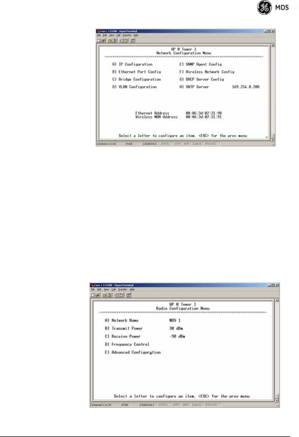
05-4446A01, Rev. E Mercury Reference Manual 65
Invisible place holder
Figure 3-32. SNTP Server Entry (on Network Configuration Menu)
When SNTP Server is selected (item H), the area to the right of the param-
eter becomes active, allowing you to enter a valid SNTP server address.
Press the Return key to make the address entry active.
3.5 RADIO CONFIGURATION
There are two primary layers in the transceiver network—radio and
data. Since the data layer is dependent on the radio layer working prop-
erly, configure and set the radio items before proceeding. This section
explains the Radio Configuration Menu, (Figure 3-33 for AP,
Figure 3-34 for Remote).
3.5.1 Radio Configuration Menu
Figure 3-33. Radio Configuration Menu
(From Access Point)
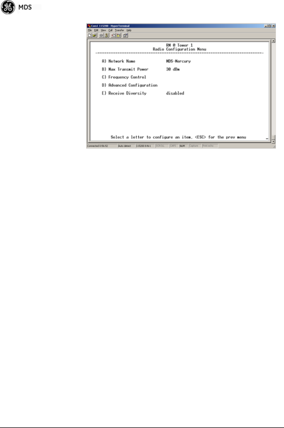
66 Mercury Reference Manual 05-4446A01, Rev. E
Invisible place holder
Figure 3-34. Radio Configuration Menu
•Network Name—The user-defined name for the wireless network.
[Any 40 character string; MDS-Mercury]
•Transmit Power (AP Only)—Sets/displays RF power output level
in dBm. This setting should reflect local regulatory limitations
and losses in antenna transmission line. (See “How Much Out-
put Power Can be Used?” on Page 169 for information on how
to calculate this value.) [0—30; 30 (900 model)] [0—23; 23 (3650 model)]
•Max Transmit Power (Remote Only)—Sets/displays maximum RF
power output level in dBm of the Remote. Power level is still
controlled by the AP, but it is limited to the maximum level set
here. This setting should reflect local regulatory limitations and
losses in antenna transmission line. (See “How Much Output
Power Can be Used?” on Page 169 for information on how to
calculate this value.) [0—30; 30 (900 model) 0—23; 23 (3650 model)
•Receive Power (AP Only)—View/set the receiver gain setpoint
for the expected strength of incoming signals from Remotes.
This setting indicates at what level (in dBm) the AP expects to
hear the Remote stations. A setting of -70 would set the AP
receiver’s gain to a relatively low level, while a setting of -85
would be a comparatively high gain setting. [-100 to -20; -75]
•Frequency Control—Opens a submenu where you can view or set
frequency mode bandwidth, channel and other parameters as
described in Frequency Control Menu below.
•Advanced Configuration—Opens a submenu where you can view
or set modulation, protection/hysteresis margins, data compres-
sion, ARQ settings, and other parameters as described in
Advanced Configuration Menu on Page 73.
•Receive Diversity (900 MHz Remote Only)—Allows enabling or
disabling the RX2 antenna port for receive operation. The use of
two antennas allows “diversity” reception which helps mini-
mize the effects of fading due to multipath reception of signals.
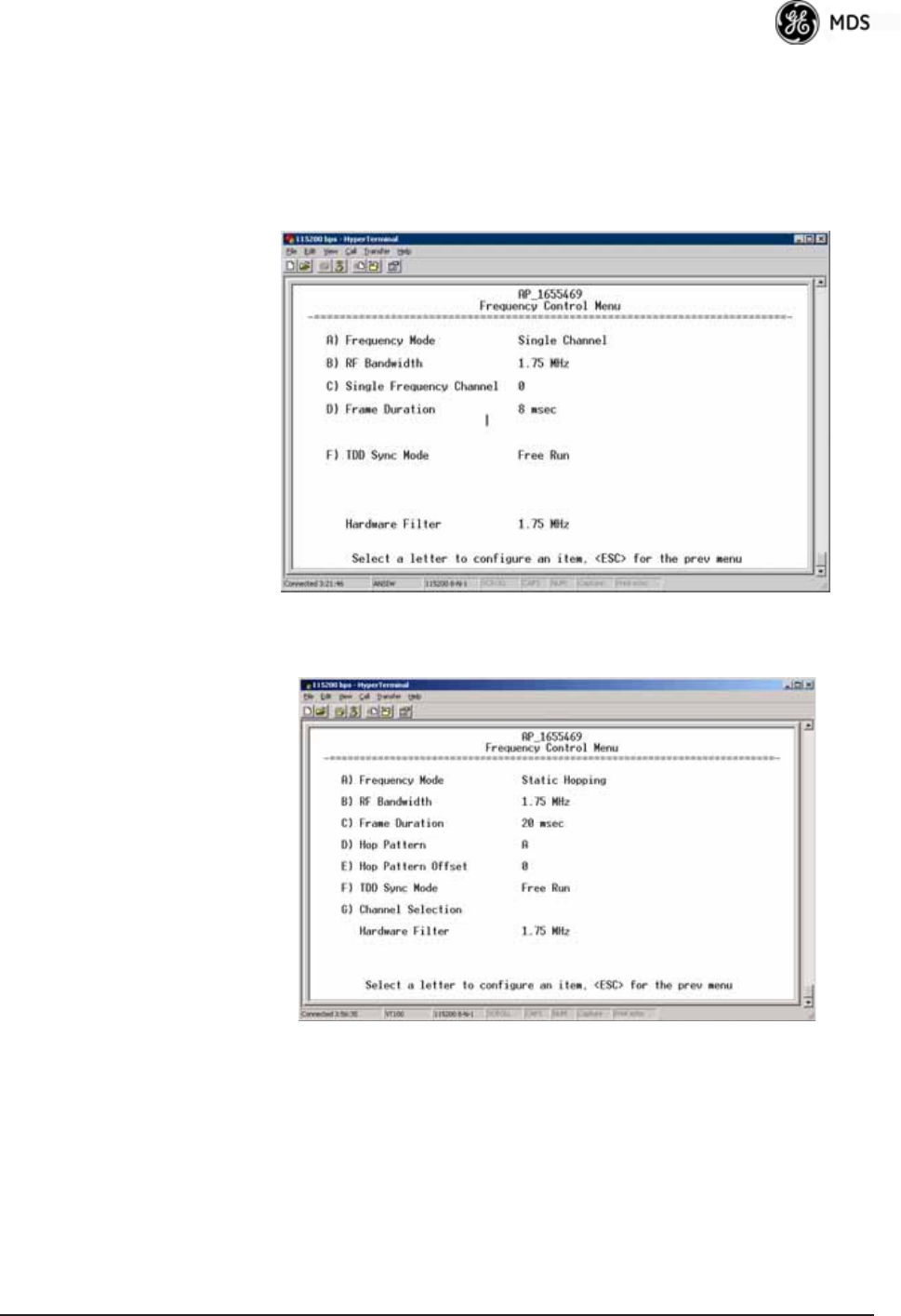
05-4446A01, Rev. E Mercury Reference Manual 67
Frequency Control Menu
The items shown on this menu vary depending on the Frequency Mode
Selection (Single Channel, Static Hopping, Hopping w/Hand-offs). Examples
of all three screens are provided below, followed by a description of the
menu items.
Invisible place holder
Figure 3-35. Frequency Control Menu
(900 MHz AP, Single Channel Freq. Mode)
Invisible place holder
Figure 3-36. Frequency Control Menu
(900 MHz AP, Static Hopping Freq. Mode)
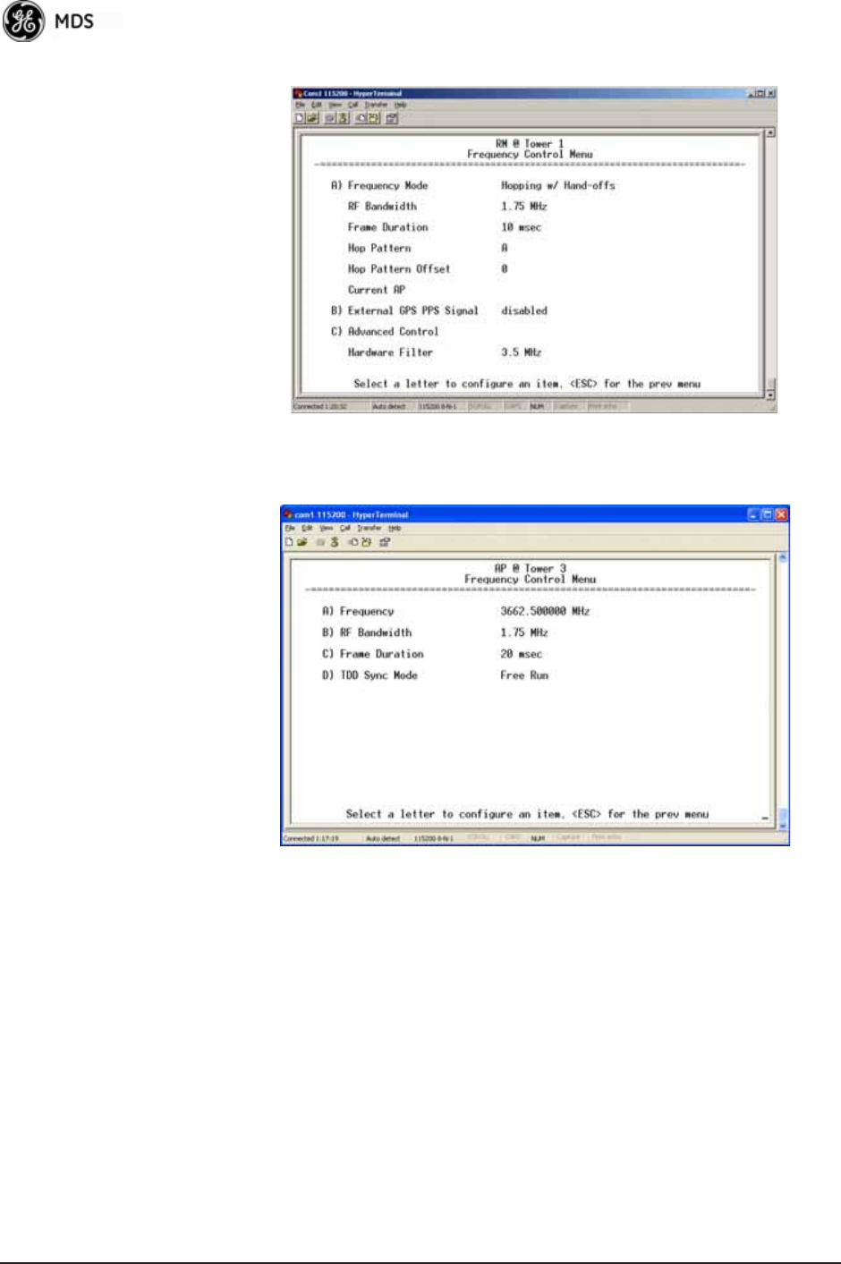
68 Mercury Reference Manual 05-4446A01, Rev. E
Figure 3-37. Frequency Control Menu
(900 MHz Remote, Hopping w/Hand-offs Freq. Mode)
Invisible place holder
Figure 3-38. Frequency Control Menu
(Mercury 3650 model only)
•Frequency (Mercury 3650 only)—Used to set/display the radio’s
operating frequency. MDS 3650 radios do not employ fre-
quency hopping, thus the entry here is a specific RF operating
channel. The allowable entry range is 3652.000 to 3673.000 MHz.
•Frequency Mode—The unit can operate on one selected fre-
quency or frequency hop. Remotes have the option of using a
static hopping configuration or using the AP locations file to
select an AP and perform hand-offs. For more information on
hand-offs, see Table 3-2 on Page 71. Changing this parameter
requires a radio reboot.
[Static Hopping, Hopping with Hand-offs, Single Channel;
Single Channel]

05-4446A01, Rev. E Mercury Reference Manual 69
NOTE: Frequency Mode Static Hopping on Access Points requires
TDD Sync Mode GPS Required.
Channel/Frequency Allocations for Single Channel 900 MHz
are shown in Table 3-1. The transceiver uses up to 14 channels
(0-13) depending on the bandwidth used (1.75 MHz or 3.5
MHz).
•RF Bandwidth—View/set the radio’s RF operating bandwidth.
Radios are factory-configured for either 1.75 MHz or 3.5
MHz maximum bandwidth. Determine the factory configu-
ration of a radio by viewing the “CONFIG” number on the
label at the bottom of the radio. 1.75 MHz units will have a
Configuration string starting with HGA/R9N1, and 3.5 MHz
units will have a string starting with HGA/R9N3.
The bandwidth setting on this menu does not necessarily
have to match the configured bandwidth of the radio, but it is
limited by it. That is, you can set a 3.5 MHz radio to either
1.75 or 3.5, but you can only set a 1.75 MHz radio to 1.75.
Note that setting a 3.5 MHz bandwidth radio to operate at
1.75 MHz bandwidth will cause a slight degradation of inter-
ference rejection capability. Note that this parameter is
read-only when Frequency Mode is set to Hopping w/Hand-offs.
[1.75MHz, 3.5MHz]
The Mercury 3650 can operate at 1.75 MHz, 3.5 MHz, 5
MHz, or 7 MHz bandwidth. The unit uses a digital filter so
that any unit can operate at any bandwidth.
Table 3-1. Channel/Frequency Allocations
Channel 1.75 MHz B/W 3.5 MHz B/W
0 903.000000 904.000000
1 904.800000 907.600000
2 906.600000 911.400000
3 908.600000 915.000000
4 910.400000 918.600000
5 912.200000 922.400000
6 914.000000 926.000000
7 916.000000
8 917.800000
9 919.600000
10 921.400000
11 923.400000
12 925.200000
13 927.000000
70 Mercury Reference Manual 05-4446A01, Rev. E
•Single Frequency Channel—The RF frequency that the inte-
grated radio will operate on when in single frequency
(non-hopping) mode. [0 to 6 for 3.5-MHz, 0 to 13 for 1.75-MHz; 0].
•Frame Duration—Defines the over-the-air media access con-
trol framing. Note that this parameter is read-only when Fre-
quency Mode is set to Hopping w/Hand-offs. [5, 8, 10, or 20 msec;
20 msec]
•Hop Pattern—Selects a pre-defined series of channels that is
followed when hopping. Note that this parameter is read-only
when Frequency Mode is set to Hopping w/Hand-offs.
•Hop Pattern Offset—Inserts an offset into the hop pattern that
is synchronized with the GPS. For example, if the offset is 0,
the start of the pattern is aligned with the GPS timing. If the
offset is 3, then the fourth hop of the pattern is aligned with
the GPS timing. All of the APs that are part of a network
should use the same pattern and each one should have its own
offset.
In the diagram below, one Remote is configured for static
hopping and will only associate with AP1 because they are
both using Offset 0. The hand-off configured Remote, using
its AP Locations file, may connect to AP1, AP2, or AP3. The
Remote does this by determining the Offset for each AP, then
configuring its radio.
•Current AP (Remote only)—Shows the name of the AP that
the Remote is trying to associate with. Note that this param-
eter is read-only when Frequency Mode is set to Hopping
w/Hand-offs.
•TDD Sync Mode (AP only)—Indicates if the Access Point’s trans-
missions should synchronize with the GPS timing. Configure
this parameter to GPS Required when the AP is configured for
Static Hopping. TDD Sync Mode (Time-Division Duplex) is use-
ful in eliminating same-network interference for multiple-AP
installations. When enabled, all AP transmissions are synchro-
nized using GPS timing information. The result is that no AP
AP 1
Pattern A
Offset 0
AP 2
Pattern A
Offset 1
AP 3
Pattern A
Offset 2
RM
Static Hopping
Offset 0
RM
Hopping w/
Hand-offs

05-4446A01, Rev. E Mercury Reference Manual 71
transmits while another is receiving, which prevents AP-to-AP
interference. Changing this parameter requires a radio reboot.
[Free Run, GPS Required; Free Run] Note: Do not use the Prefer GPS
setting.
•Channel Selection (AP only)—Opens a submenu where you can
specify channel usage.
•External GPS PPS Signal—Indicates whether or not an external
Pulse Per Second (PPS) signal is available. The setting may be
changed by pressing the spacebar after selection of the menu
item. This allows the radio to use the proper timing scheme
when frequency hopping.
•Advanced Control (Remote only)—Brings up a submenu (see
Figure 3-39) where additional communication parameters may
be set.
•Hardware Filter (900 MHz only)—This field provides a read-only
indication of the maximum bandwidth of the radio. [1.75 MHz or
3.5 MHz]
Hand-Off Mode
Parameters In a mobile or portable application, a Remote radio can move and asso-
ciate with different APs depending on its location. The process by which
the Remote ends the connection with one AP and begins a connection
with another AP is called “hand-off.” Table 3-2 lists the hand-off
parameters for Remote transceivers and explains how they operate
under different signal conditions.
Table 3-2. Remote Hand-Off Parameters
Strict
Distance
Strict
Connection
Strict
Signal
Signal and
Distance
Signal, Dis-
tance, and
Bearing
Description The Remote
always chooses
the closest AP
regardless of
connection
status, RSSI,
etc.
The Remote will
only choose a
new AP when
the modem link
is lost.
The Remote
chooses a new
AP when the
modem link is
lost or when the
RSSI or SNR
falls below the
threshold. The
Remote then
chooses the
closest AP.
Operates the
same way as the
Strict SIgnal
method except
that the current
AP is abandoned
only if the next
AP is within the
distance
threshold.
Operates the
same way as the
Signal and
Distance method
except that the
current AP is
abandoned only
if the bearing is
away from the
current AP.
AP(s) Used
(see note be-
low Table 3-2)
Only closest AP. Closest 3 APs. Closest 3 APs. Closest 3 APs;
AP must be
within Distance
Threshold.
Closest 3 APs;
AP must be
within Distance
Threshold.
Max. Scanning
Seconds
N/A Applicable Applicable Applicable Applicable
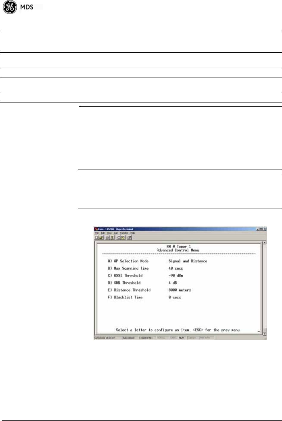
72 Mercury Reference Manual 05-4446A01, Rev. E
NOTE: In Table 3-2 above, modes using the “Closest 3 APs” first
attempt to connect to the closest AP. If after the maximum
number of scanning seconds (Max. Scanning Seconds) a link is
not established, then the next closest AP is chosen. If after
another maximum number of scanning seconds a link is not
established, then the third closest AP is chosen. If a link still is
not established, the Remote again chooses the closest AP and
continues this cycle until it is associated to one of the APs.
NOTE: In Table 3-2 above, modes which use the RSSI and SNR Thresh-
olds use them in an “or” logic fashion. That is, if the RSSI is
below the set threshold OR the SNR is below threshold, the
Remote drops the current AP.
Advanced Control Menu Invisible place holder
Figure 3-39. Advanced Control Menu
(Hopping with Handoff Mode, Remote Only)
AP Selection Mode—The method used by the Remote to determine what
AP to connect to. It may be based on Signal, Distance and Bearing (from
the AP's GPS coordinates in the AP locations file), or Connection.
Table 3-2 on Page 71 summarizes these parameters and other selections
on this menu.
RSSI
Threshold
N/A N/A Applicable Applicable Applicable
SNR Threshold N/A N/A Applicable Applicable Applicable
Distance
Threshold
N/A N/A N/A Applicable Applicable
Blacklist Time N/A Applicable Applicable Applicable Applicable
Table 3-2. Remote Hand-Off Parameters
Strict
Distance
Strict
Connection
Strict
Signal
Signal and
Distance
Signal, Dis-
tance, and
Bearing
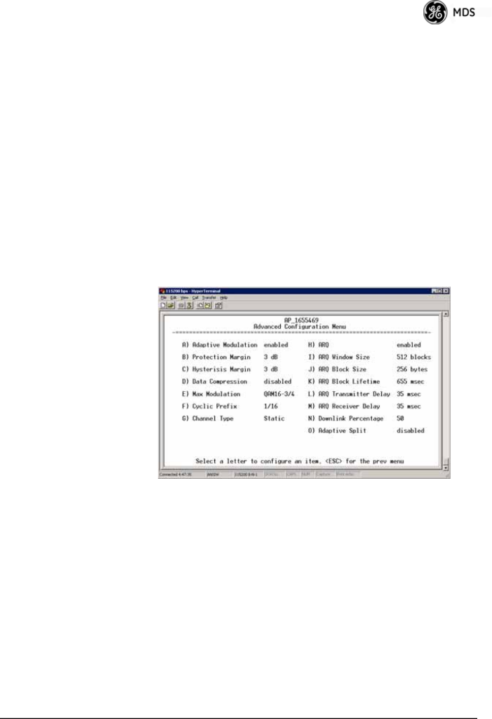
05-4446A01, Rev. E Mercury Reference Manual 73
Max Scanning Time—The maximum time to try to connect to an AP before
trying the next one in the AP Locations file.
RSSI Threshold—The RSSI cutoff for Signal modes. When the RSSI drops
below this value, the Remote disconnects and looks for a new AP.
SNR Threshold—The SNR cutoff point for Signal modes. When the SNR
drops below this value, the Remote disconnects and looks for a new AP.
Distance Threshold—The distance cutoff when operating in Distance
mode. When the Remote's AP gets farther away than this distance, it dis-
connects and look for a new AP.
Blacklist Time—The amount of time (in seconds) that an AP is ignored
when the Remote is trying to find a better connection.
Advanced Configuration Menu Invisible place holder
Figure 3-40. Advanced Configuration Menu
•Adaptive Modulation—Enables automatic selection of modulation
and FEC rate based on SNR. [enabled, disabled; enabled]
•Protection Margin—A number of decibels of SNR added to the
minimum SNR required for a given modulation and FEC rate.
See “Modulation Protection and Hysteresis Margins” on
Page 75 for more information. [0-50; 3]
•Hysteresis Margin—A number of decibels of SNR added to the
maximum SNR required before shifting to the next higher mod-
ulation and FEC rate. See “Modulation Protection and Hyster-
esis Margins” on Page 75 for more information. [0-50; 3]
•Data Compression—This setting determines whether over-the-air
data packets will be compressed. [enabled, disabled; enabled]

74 Mercury Reference Manual 05-4446A01, Rev. E
•Max Modulation—Sets the highest modulation speed the trans-
ceiver will use.
[BPSK, QPSK-1/2, QPSK-3/4, 16QAM-1/2, 16QAM-3/4, 64QAM-2/3;
QAM16-3/4]
•Cyclic Prefix (AP only)—Amount of additional information
added to the over-the-air packets to mitigate the effects of chan-
nel multipath. [1/4, 1/8, 1/16,1/32; 1/16]
•Channel Type (AP only)—This parameter, available on Access
Point units, must be set appropriately according to the signal
conditions of a network. For installations with strong signals,
low interference, and minimal fading, set the Channel Type
parameter to Static. This setting is generally appropriate for
Access Points whose Remotes are in fixed locations. It supports
a large offered payload with high packet rates.
For installations with significant interference and fading or
nomadic/mobile Remotes, set the Channel Type parameter to
Dynamic. [Static, Dynamic; Static]
•ARQ (AP only)—Enables the Automatic Repeat Request func-
tion.
[enable, disable; enabled]
•ARQ Window Size (AP only)—The maximum number of blocks to
send before receiving an acknowledgement. [1—1024; 512]
•ARQ Block Size (AP only)—ARQ is applied to payload data in
blocks of this size. [4—2040; 256]
•ARQ Block Lifetime (AP only)—ARQ blocks are valid for this
length of time. [0—655; 655]
•ARQ Transmitter Delay (AP only)—The length of time the trans-
mitter waits before repeating an unacknowledged packet.
[1—655; 35]
•ARQ Receiver Delay (AP only)—The length of time the receiver
waits before repeating an unacknowledged packet. [1—655; 35]
•Downlink Percentage (AP only)—The percentage of link time
given to downstream traffic. It should be set to 50% when Adap-
tive Split is set to enabled. [10-90%; 50%]
•Adaptive Split (AP only)—The adaptive split feature provides
improved link utilitization and throughput for burst payload
traffic. The Mercury is a TDD system and normally allocates
50% of its capacity to the downlink and 50% to the uplink.
When adaptive split is enabled, the Media Access Controller
(MAC) in the Access Point monitors the traffic flow continu-
ously in the downlink and uplink directions. The MAC automat-
ically modifies the downlink split in response to the traffic load.
When more traffic is flowing upstream, the downlink split
changes to allocate additional capacity to the uplink. When
more traffic is flowing downstream, the downlink gets addi-
tional capacity. If TDD synchronization is used to synchronize
Access Points and minimize inter-Access Point interference,
Adaptive Split should be disabled. [enabled, disabled; enabled]

05-4446A01, Rev. E Mercury Reference Manual 75
Modulation
Protection and
Hysteresis Margins
Table 3-3 on Page 75 shows the relationship between the radio’s Protec-
tion Margin, Hysteresis Margin, and the SNR range allowed for each
form of modulation.
Column A lists the available modulation types for the radio, while col-
umns B and C show the minimum SNR range required to operate in each
modulation. For example, an SNR of 5.8 dB in Column B is required for
QPSK modulation with an FEC rate of 1/2. An SNR of 8.4 dB is
required for QPSK modulation with an FEC rate of 3/4.
Columns B and C have a Hysteresis Margin of 0 dB. This means there
is no overlap between the maximum SNR for BPSK (5.8 dB) and the
minimum SNR for QPSK-1/2 (5.8 dB).
Columns D and E show the SNR ranges with a Protection Margin and
Hysteresis Margin of 3 dB. The Protection Margin is added to each
value in Columns B and C to get the corresponding value in Columns D
and E. The Hysteresis Margin is then added to the Max SNR value.
For example, the third SNR value in Column D is 11.4 dB (8.4 + 3 =
11.4 dB), and the third SNR value in Column E is 17.1 (11.1 + 3 + 3 =
17.1 dB). Note that with a Hysteresis Margin of 3 dB, there is an overlap
of 3 between the Max SNR of one modulation and the Min SNR of the
next higher modulation.
In this case, if a link is operating with an SNR of 15 dB, then QPSK-3/4
modulation is used. The SNR must go above 17.1 dB before the link
shifts up to 16QAM-1/2 modulation. Conversely, the SNR will need to
drop below 11.4 dB before the link shifts down to QPSK-1/2.
The blank entries (--) in the table indicate infinite SNR (i.e., the top of
the range). For example, in columns B and C, 64QAM-3/4 modulation
is used for all SNR values from 20 dB and up.
Table 3-3. Adaptive Modulation Protection and Hysteresis Margins
A B C D E F G
Protection 0 Protection 3 Protection 5
Hysteresis 0 Hysteresis 3 Hysteresis 3
Min SNR Max SNR Min SNR Max SNR Min SNR Max SNR
BPSK 3.3 5.8 3.3 11.8 3.3 13.8
QPSK-1/2 5.8 8.4 8.8 14.4 10.8 16.4
QPSK-3/4 8.4 11.1 11.4 17.1 13.4 19.1
16QAM-1/2 11.1 14.4 14.1 20.4 16.1 22.4
16QAM-3/4 14.4 18.4 17.4 24.4 19.4 26.4
64QAM-2/3 18.4 20 21.4 26 23.4 28
64QAM-3/4 20 -- 23 -- 25 --

76 Mercury Reference Manual 05-4446A01, Rev. E
3.5.2 Serial Port Configuration
Overview
The transceiver includes an embedded serial device server that provides
transparent encapsulation over IP. In this capacity, it acts as a gateway
between serial and IP devices. Two common scenarios are PC applica-
tions using IP to talk to remote devices, and serial PC applications
talking to remote serial devices over an IP network. These data services
are available from the COM1 port of the radio.
COM1 Port—Dual
Purpose Capability The COM1 port is used as a local console connection point and to pass
serial data with an external device. Setting the COM1 port status to Enable
prevents access to the Management System (MS) through this port.
However, the MS can still be accessed via the LAN port using Telnet or
a web browser.
NOTE: To restore the COM1 port to support Management System
services, connect a terminal to the port, select the proper baud
rate (115,200 is default), and enter an escape sequence (+++) to
reset it to the console mode.
There is a configuration parameter for the console baud rate and
another parameter for the serial data baud rate. These items can
be different, so when switching out of data mode to console
mode, the port might also change its baud rate.
TCP vs. UDP TCP and UDP services are used by the transceiver’s embedded serial
device server. TCP provides a connection-oriented link with end-to-end
acknowledgment of data, but with some added overhead. UDP provides
a connectionless best-effort delivery service with no acknowledgment.
Most polled protocols are best served by UDP service as the protocol
itself has built-in error recovery mechanisms. UDP provides the needed
multidrop operation by means of multicast addressing.
On the other hand, TCP services are best suited for applications without
a recovery mechanism (error-correction) and must have the guaranteed
delivery that TCP provides in spite of the extra overhead. The
IP-to-Serial Application Example on Page 83 shows how to do this.
Serial Encapsulation Transparent encapsulation, or IP tunneling, provides a mechanism to
encapsulate serial data in an IP envelope. All bytes received through the
serial port are put into the data portion of a TCP or UDP packet (TCP or
UDP are user-configurable options). In the same manner, all data bytes
received in a TCP or UDP packet are output through the serial port.
When the radio receives data through the serial port, it is buffered until
the packet is received completely. There are two events that signal an
end-of-packet to the radio: a period of time since the last byte was

05-4446A01, Rev. E Mercury Reference Manual 77
received, or a number of bytes that exceed the buffer size. Both of these
triggers are user-configurable.
One radio can perform serial data encapsulation (IP-to-Serial) and talk
to a PC. You can use two radios together (or one radio and a terminal
server) to provide a serial-to-serial channel. For more information, see
“IP-to-Serial Application Example” on Page 83 and Point-to-Point
Serial-to-Serial Application Example on Page 83.
TCP Client vs. TCP
Server On a TCP session there is a server side and a client side. You can con-
figure the transceiver to act as either a server or a client. The server
always waits for requests from clients.
The client mode attempts to establish a connection to a server (typically
running on a PC) whenever it receives data on the serial port. There is
also a Client/Server mode, where the client establishes a connection
when data is received on the serial port and the server is not currently
handling a connection.
UDP Multicast IP provides a mechanism to perform a limited broadcast to a specific
group of devices. This is known as multicast addressing. Multicast
addressing requires the use of a specific branch of IP addresses set apart
by the Internet Assigned Numbers Authority (IANA) for this purpose.
UDP multicast is generally used to transport polling protocols typically
used in SCADA applications where multiple remote devices will
receive and process the same poll message.
As part of the Multicast implementation, the radio sends IGMP mem-
bership reports and IGMP queries, and responds to membership queries.
It defaults to V2 membership reports, but responds to both V1 and V2
queries.
The Point-to-Multipoint Serial-to-Serial Application Example on
Page 84 shows how to provide multicast services.
Data Buffering Data buffering is always active regardless of the selected mode. If you
connect EIA-232 serial devices to the transceiver, review these parame-
ters carefully.
Serial Configuration Wizard
GE MDS recommends the Serial Configuration Wizard, available
through the Serial Port Configuration Menu, for configuration of the serial
terminal services. The wizard uses a step-by-step process, eliminates
possible conflicting settings, and streamlines complex configurations.
You can bypass the wizard by selecting option B) View Current Settings
and adjusting the individual settings of the appropriate parameter.
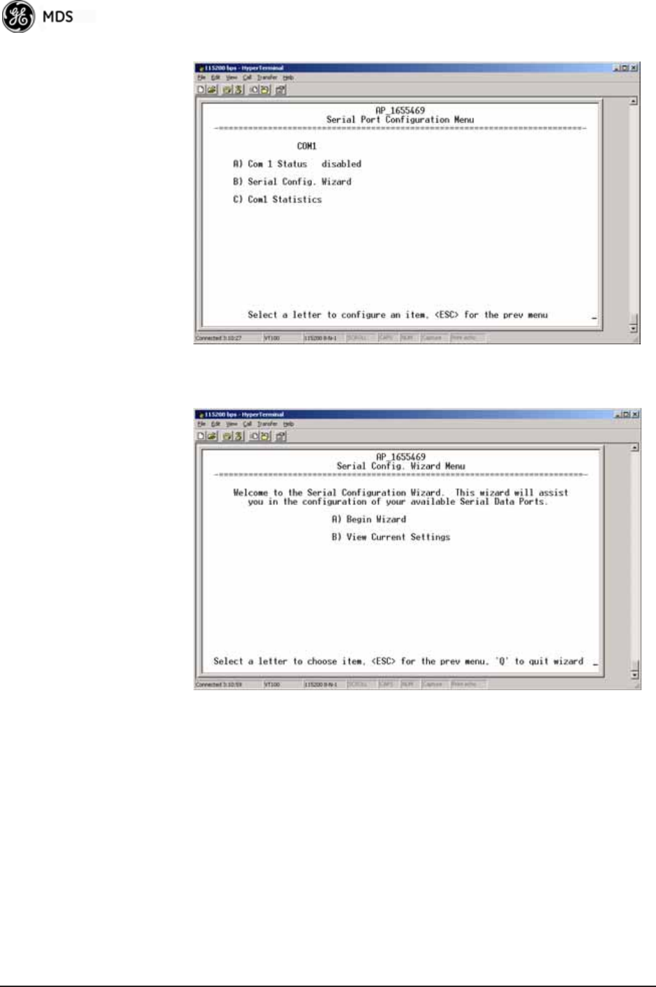
78 Mercury Reference Manual 05-4446A01, Rev. E
Serial Port
Configuration Menu Invisible place holder
Figure 3-41. Serial Port Configuration Menu
Figure 3-42. Serial Configuration Wizard
•Begin Wizard—Tool for configuring serial ports using a
step-by-step process.
•View Current Settings—Displays all setable options. Varies
depending on the selected IP protocol.
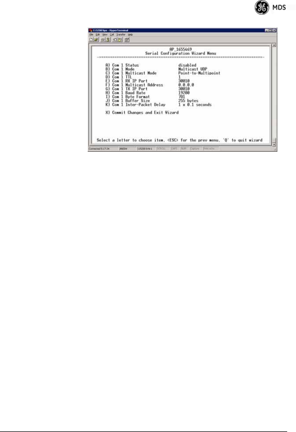
05-4446A01, Rev. E Mercury Reference Manual 79
Configuring for UDP
Point-to-Multipoint Invisible place holder
Figure 3-43. UDP Point-to-Multipoint Menu
Use UDP point-to-multipoint to send a copy of the same packet to mul-
tiple destinations, such as in a polling protocol.
•Status—Enable/Disable the serial data port.
•Mode—The type of IP port offered by the transceiver’s serial
device server. [TCP, UDP; TCP]
•RX IP Port—Receive IP data from this source and pass it
through to the connected serial device. The port number must
be used by the application connecting to local TCP or UDP
socket. [Any valid IP port; 30010]
•TX IP Address (used instead of Local IP Address when using
UDP Point-to-Multipoint)— Configure with a valid Multi-
cast address (224.0.0.0–239.255.255.255). IP packets
received with a matching destination address are processed
by this unit. [Any legal IP address; 0.0.0.0]
•TX IP Port (used instead of Local IP Port when using UDP
Point-to-Multipoint)—This port number must match the
number used by the application connecting to local TCP or
UDP socket. [1-64,000; 30010]
•Baud Rate—Data rate (payload) for the COM port, in
bits-per-second. [1,200—115,200; 19200]
•Byte Format—Formatting of data bytes, representing data bits,
parity and stop bits. [7N1, 7E1, 7O1, 8N1, 8E1, 8O1, 8N1, 7N2, 7E2,
7O2, 8N2, 8E2, 8O2; 8N1]
•Buffer Size—Maximum amount of characters that the Remote
end buffers locally before transmitting data through the serial
port. [1—255; 255]
•Inter-Packet Delay—Amount of time that signal the end of a
message, measured in tenths of a second. [default = 1 (that is,
1/10th of a second)]
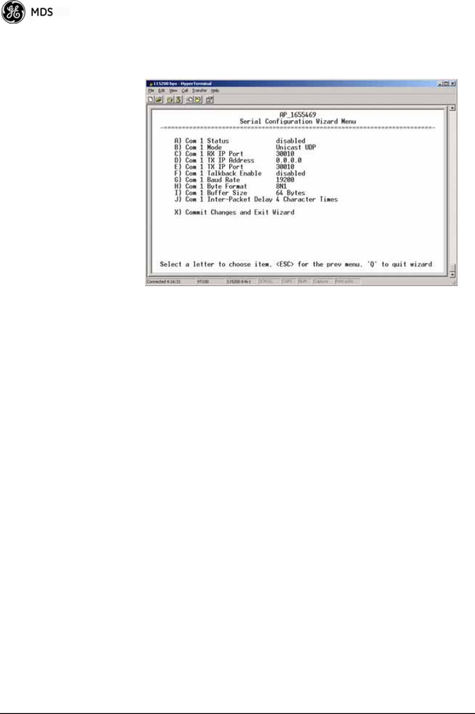
80 Mercury Reference Manual 05-4446A01, Rev. E
•Commit Changes and Exit Wizard—Save and execute changes
made on this screen (shown only after changes have been
entered). Invisible place holder
Figure 3-44. UDP Point-to-Point Menu
Configuring for UDP
Point-to-Point Use UDP point-to-point configuration to send information to a single
device.
•Status—Enable/Disable the serial data port.
•Mode—UDP Point-to-Point. This is the type of IP port
offered by the transceiver’s serial device server.
[TCP, UDP; TCP]
•RX IP Port—Port number where data is received and passed
through to the serial port. The application connecting to this
transceiver must use this port number.
[1—64,000; 30010]
•TX IP Address—Data received through the serial port is sent to
this IP address. To reach multiple Remotes in the network,
use UDP Point-to-Multipoint.
[Any legal IP address; 0.0.0.0]
•TX IP Port—The destination IP port for data packets received
through the serial port on the transceiver.
[1—64,000; 30010]
•Talkback Enable—Talkback is a mode where the radio returns
a serial message received within a time-out period back to the
last address of an incoming UDP message. If the time-out
expires, the unit sends the serial data to the configured
address. [Enable, Disable; Disabled]
•Baud Rate—Data rate (payload) for the COM port, in
bits-per-second. [1,200—115,200; 19200]
•Byte Format—Formatting of data bytes. Data bits, parity and
stop bits. [7N1, 7E1, 7O1, 8N1, 8E1, 8O1, 8N1, 7N2, 7E2, 7O2, 8N2,
8E2, 8O2; 8N1]
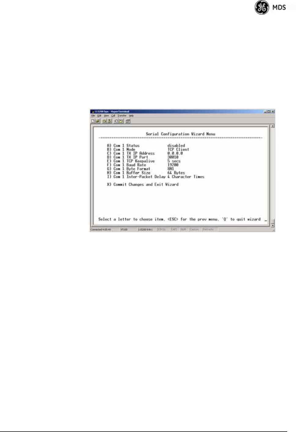
05-4446A01, Rev. E Mercury Reference Manual 81
•Buffer Size—Maximum amount of characters that the Remote
end buffers locally before transmitting data through the serial
port. [1—255; 255]
•Inter-Packet Delay—Amount of time that signal the end of a
message, measured in tenths of a second. [default = 1 (that is,
1/10th of a second)]
•Commit Changes and Exit Wizard—Save and execute changes
made on this screen (shown only after changes have been
entered).
Configuring for TCP
Mode Invisible place holder
Figure 3-45. TCP Client Menu (Remote)
•Status—Enable/Disable the serial data port.
•Mode—TCP Client. This is the type of IP port offered by the
transceiver’s serial device server. [TCP, UDP; TCP]
•TX IP Address—The IP address to be used as a destination for
data received through the serial port.
[Any legal IP address; 0.0.0.0]
•TX IP Port—The destination IP port for data packets received
through the serial port on the transceiver.
[Any valid IP port; 30010]
•TCP Keepalive—Amount of time (in seconds) that the trans-
ceiver waits for data before terminating the TCP session.
[0—600; 600]
•Baud Rate—Data rate (payload) for the COM port, in
bits-per-second. [1,200—115,200; 19200]
•Byte Format—Interface signaling parameters. Data bits, parity
and stop bits.
[7N1, 7E1, 7O1, 8N1, 8E1, 8O1, 8N1, 7N2, 7E2, 7O2, 8N2, 8E2, 8O2;
8N1]
•Buffer Size—Maximum amount of characters that the Remote
end buffers locally before transmitting data through the serial
port. [1—255; 255]
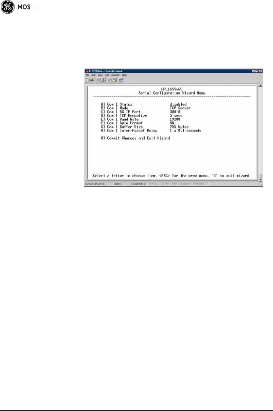
82 Mercury Reference Manual 05-4446A01, Rev. E
•Inter-Frame Packet Delay—A measurement representing the
end of a message, measured in tenths of a second.
[default = 1 (that is, 1/10th of a second)]
•Commit Changes and Exit Wizard—Save and execute changes
made on this screen (shown only after changes have been
entered). Invisible place holder
Figure 3-46. TCP Server Menu (AP)
•Status—Enable/Disable the serial data port.
•Mode—TCP Server. This is the type of IP port offered by the
transceiver’s serial device server.
[TCP, UDP; TCP]
•RX IP Port—Receive IP data from this source and pass it
through to the connected serial device. The application con-
necting to the local TCP or UDP socket must use this port
number.
[Any valid IP port; 30010]
•Baud Rate—Data rate (payload) for the COM port, in
bits-per-second. [1,200—115,200; 19200]
•Byte Format—Interface signaling parameters. Data bits, parity
and stop bits.
[7N1, 7E1, 7O1, 8N1, 8E1, 8O1, 8N1, 7N2, 7E2, 7O2, 8N2, 8E2, 8O2;
8N1]
•Buffer Size—Maximum amount of characters that the Remote
end buffers locally before transmitting data through the serial
port. [1—255; 255]
•Inter-Packet Delay—Amount of time that signal the end of a
message, measured in tenths of a second. [default = 1 (that is,
1/10th of a second)]
•Commit Changes and Exit Wizard—Save and execute changes
made on this screen (shown only after changes have been
entered).
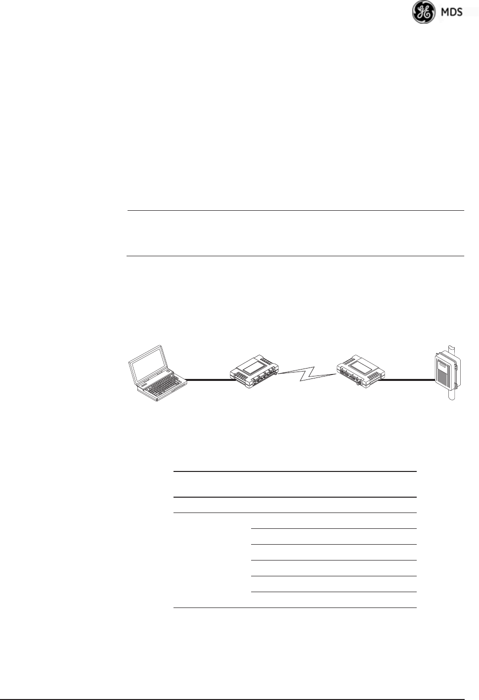
05-4446A01, Rev. E Mercury Reference Manual 83
IP-to-Serial Application Example
You must choose UDP or TCP to establish communications. This
depends on the type of device you are communicating with at the other
end of the IP network. In this example, we will use TCP to illustrate its
use.
In TCP mode, the transceiver remains in a passive mode, offering a
socket for connection. Once a request is received, data received at the
serial port is sent through the IP socket and vice versa, until the connec-
tion is closed or the link is interrupted. In this mode, the transceiver
behaves the same, whether it is an Access Point or a Remote.
(See Figure 3-47 and Table 3-4)
NOTE: The TCP session has a timeout of 10 minutes (600 seconds). If
inactive for that time, the session is closed. The transceiver
offers the port again for connection after this time expires.
Establishing a
Connection From the PC, establish a TCP connection to the IP address of the
Remote transceiver and to the IP port as configured above (30010). Use
a Telnet client application to establish this connection. Data can now be
sent between the PC and the RTU or other connected device.
Invisible place holder
Figure 3-47. IP-to-Serial Application Diagram
Point-to-Point Serial-to-Serial Application Example
Once you have configured the transceivers, they begin processing data
presented at the COM ports. Data presented at the Access Point’s COM
port is packetized and sent via UDP to the Remote. Upon receiving the
Ethernet
Crosssover
RTU
EIA-232
Computer
or Network
192.168.0.10 192.168.0.1 192.168.0.2
LA
NCOM
1COM
2PW
RLIN
K
Remote
Access Point
Table 3-4. Serial Port Application Configuration
IP-to-Serial Connection
Transceiver
Location
Menu Item Setting
Access Point None is required None is required
Remote Unit IP Address 192.168.0.2
Status Enabled
IP Protocol TCP
Baud Rate 9,600 (Example)
Flow Control None
Local IP Port 30010

84 Mercury Reference Manual 05-4446A01, Rev. E
packet, the Remote strips the data out of the UDP packet and sends it out
its COM port. Likewise, data presented at the Remote’s COM port is
packetized, sent to the Access Point, stripped, and sent out the Access
Point’s COM port. This configuration does not use multicast addressing.
Invisible place holder
Figure 3-48. Point-to-Point Serial-to-Serial Application Diagram
Point-to-Multipoint Serial-to-Serial Application Example
The operation and data flow for this mode is very similar to
Point-to-Point serial-to-serial application, except that it uses multicast
addressing. The primary difference is that data presented at the Access
Point’s COM port is packetized and sent using UDP to all of the
Remotes. Upon receiving the packet, all of the Remotes strip the data
from the UDP packet and send it out their COM ports. Likewise, data
presented at any of the Remotes’ COM ports is packetized, sent to the
Access Point, stripped, and sent out the Access Point’s COM port (see
Figure 3-49, Table 3-6, Figure 3-50, and Figure 3-51 on Page 86).
EIA-232
RTU
EIA-232
Terminal
or Computer
192.168.0.10 192.168.0.1 192.168.0.2
Remote
Access Point
LA
NCOM
1COM
2PW
RLIN
K
Table 3-5. Serial Port Application Configuration
Transceiver Location Menu Item Setting
Access Point (COM1) Status Enabled
Data Baud Rate 9,600 (Example)
SIFD 4
IP Protocol UDP
Remote IP
Address
192.168.0.2
(IP address of the Remote radio)
Remote IP Port 30010
Local IP Port 30010
Remote Unit (COM1) Status Enabled
Data Baud Rate 9,600 (Example)
Flow Control X-ON/X-OFF (Example)
SIFD 4 (Characters)
IP Protocol UDP
Remote IP
Address
192.168.0.1
(IP address of the AP)
Remote IP Port 30010
Local IP Port 30010
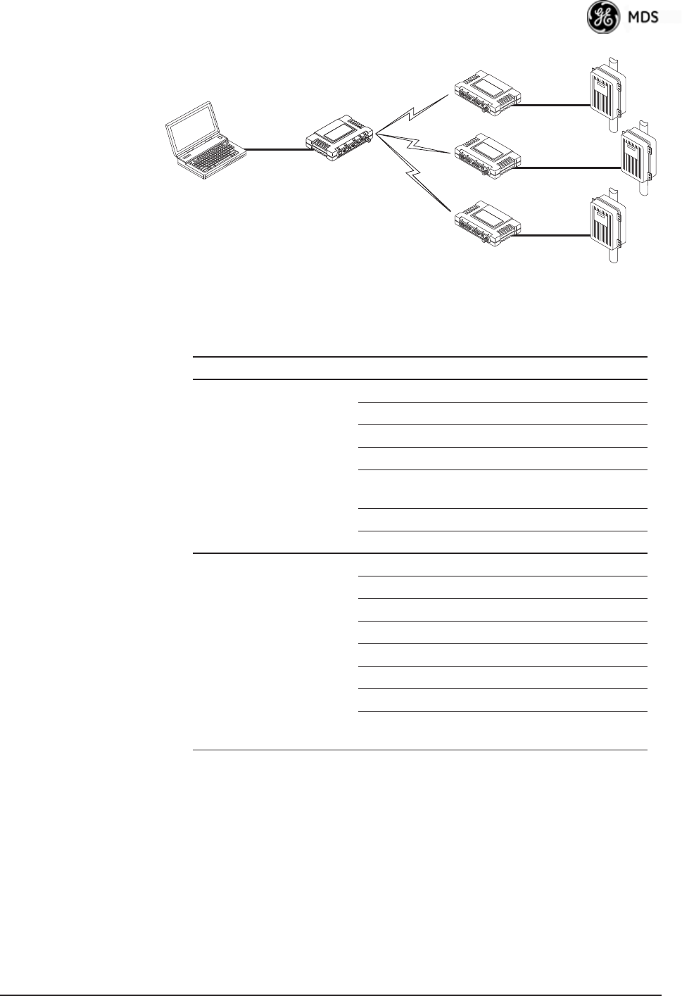
05-4446A01, Rev. E Mercury Reference Manual 85
Invisible place holder
Figure 3-49. Point-to-Multipoint Serial-to-Serial Application
Diagram
Invisible place holder
192.168.0.3
192.168.0.4
EIA-232
Terminal
or Computer
RTU
RTU
RTU
EIA-232
EIA-232
EIA-232
192.168.0.10 192.168.0.1
192.168.0.2
Access Point
LA
NCOM
1COM
2PW
RLIN
K
Remote
LA
NCOM
1COM
2PW
RLIN
K
Remote
LA
NCOM
1COM
2PW
RLIN
K
Remote
Table 3-6. Serial Port Application Configuration
Transceiver Location Menu Item Setting
Access Point (COM1) Status Enabled
Baud Rate 9600 (Example)
Flow Control Disabled
IP Protocol UDP
Remote IP Address 224.254.1.1—
Multicast Address1
Remote IP Port 30010
Local IP Port 30010
Remote Units (COM1) Enable Enabled
Baud Rate 2,400 (Example)
Flow Control Hardware (Example)
IP Protocol UDP
Remote IP Address 192.168.0.1
Remote IP Port 30010
Local IP Port 30010
Local Multicast
Address
224.254.1.1 —
Multicast Address2
1. This address is an example only. Any Class D IP address
(224.0.0.0—239.255.255.255) will work.
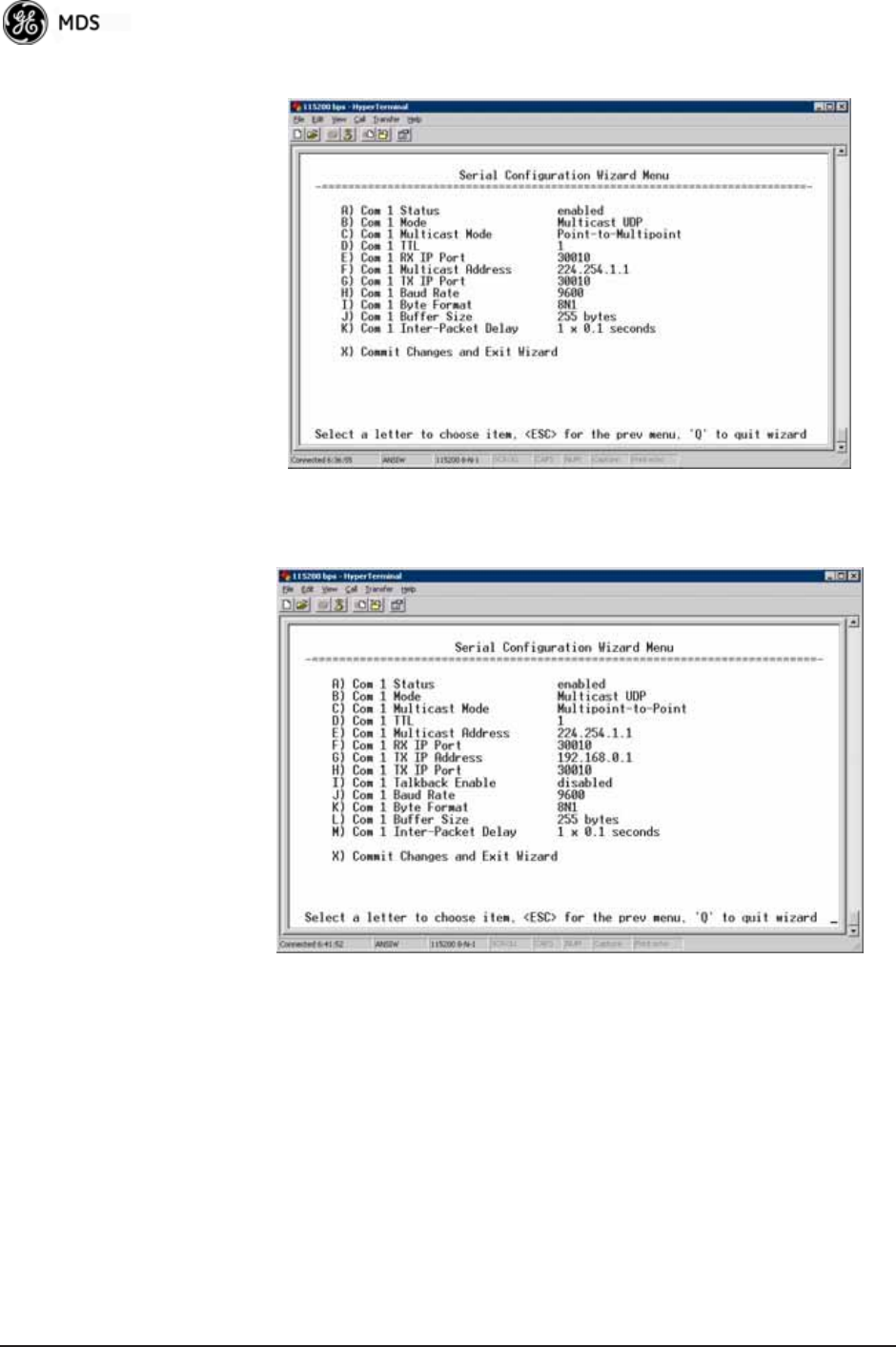
86 Mercury Reference Manual 05-4446A01, Rev. E
Figure 3-50. Serial Port ConfigurationAccess Point
Figure 3-51. Radio Serial Port ConfigurationRemote
Mixed Modes
In this example, the TCP mode does not involve the Access Point. Thus,
the transceiver in a single network can run in both modes at the same
time. In other words, you can configure some Remotes for TCP mode
and others (along with the Access Point) for UDP mode.
In this configuration, the Host PC can use both data paths to reach the
RTUs. This is helpful when a mixed collection of RTUs is present where
some RTUs can operate in a broadcast form while others cannot (see
Figure 3-52 on Page 87 and Table 3-7 on Page 87).
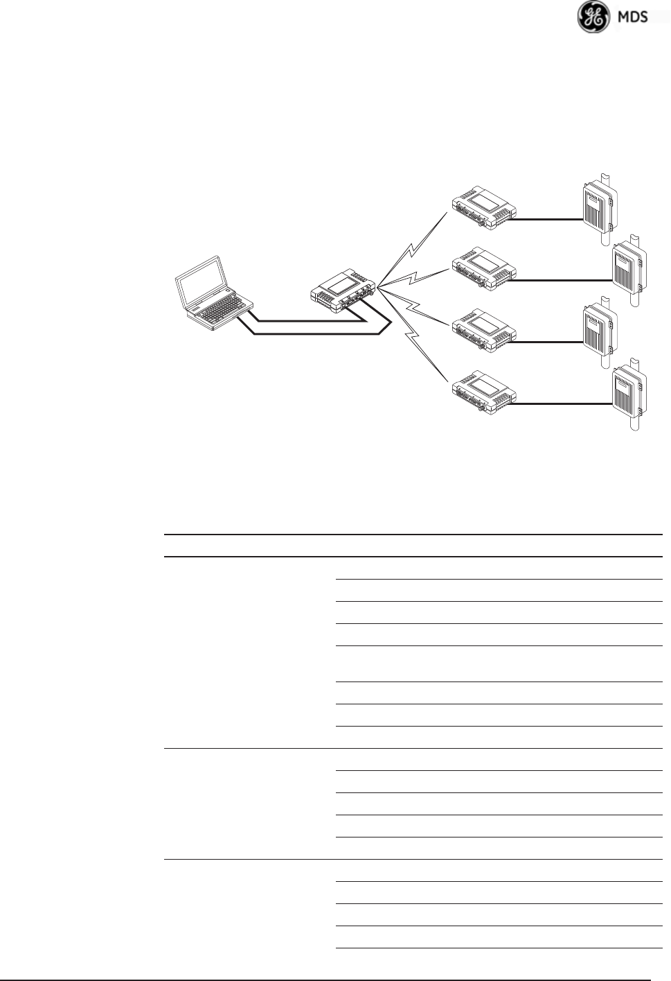
05-4446A01, Rev. E Mercury Reference Manual 87
Operation and Data
Flow • Communicate with RTU A by Telneting to Remote 1, port 30010.
• Communicate with RTU B by Telneting to Remote 2, port 30010.
• Communicate with RTUs C and D by sending and receiving data
from the Access Point’s COM port.
• All communication paths can be used simultaneously.
Invisible place holder
Figure 3-52. Mixed-Modes Application Diagram
EIA-232
Terminal
or Computer
RTU–C
EIA-232
EIA-232
EIA-232
RTU–D
EIA-232
Ethernet
Crosssover
RTU–B
RTU–A
Access Point
Transceiver
LA
NCOM
1COM
2PW
RLIN
K
Remote 1
LA
NCOM
1COM
2PW
RLIN
K
Remote 2
LA
NCOM
1COM
2PW
RLIN
K
Remote 3
LA
NCOM
1COM
2PW
RLIN
K
Remote 4
Table 3-7. Serial Port Application Configuration
Transceiver Location Menu Item Setting
Access Point Status Enabled
Baud Rate 9,600
Flow Control Disabled
IP Protocol UDP
Send to Address A multicast IP address such as
224.254.1.1
Send to Port 30010
Receive on Port 30010
Receive on Address 0.0.0.0 (Not Used)
Remote Units 1 & 2 (COM1) Status Enabled
Baud Rate 2,400
Flow Control Disabled
IP Protocol TCP
Receive on Port 30010
Remote Units 3 & 4 (COM1) Status Enabled
Baud Rate 9,600
Flow Control Disabled
IP Protocol UDP

88 Mercury Reference Manual 05-4446A01, Rev. E
3.6 MODBUS / TCP SERVER
CONFIGURATION
Modbus is a serial communications protocol developed by Schneider
Electric (Modicon) for communication between programmable logic
controllers (PLCs), remote terminal units (RTUs) and other industrial
electronic devices. It has become an established standard in the industry,
and is now used by many manufacturers of industrial data equipment.
Mercury Series transceivers running version 2.2.0 firmware or later
include Modbus functionality. This section of the addendum contains an
overview of the Modbus/TCP Server and provides menu details for
using this feature. You should also review Configuring for TCP Mode
section on Page 81.
NOTE: This material assumes you have an understanding of Ethernet
networking, TCP/IP, and Modbus serial protocols. Refer to the
following web site for additional information:
www.modicon.com/TECHPUBS/intr7.html.
NOTE: Modbus/TCP functionality is provided on the COM1 port of
the transceiver only.
3.6.1 Modbus/TCP in Mercury Transceivers—An
Overview
The transceiver implements a Modbus/TCP server that bridges
Modbus/TCP to either: Modbus RTU or Modbus/ASCII. It does not
function as a Modbus/TCP client.
The transceiver converts Modbus/TCP requests to either RTU or ASCII
serial Modbus packets and sends them to the configured serial port. It
waits up to the timeout period for a reply on the serial port, and if one
arrives, it converts the response back to Modbus/TCP and sends it to the
connected Modbus/TCP client.
Send to Address IP address of the AP
Send to Port 30010
Receive on Port 30010
Receive on Address 224.254.1.1
(The multicast IP address used
for the AP’s Send To Address
above)
Table 3-7. Serial Port Application Configuration (Continued)
Transceiver Location Menu Item Setting
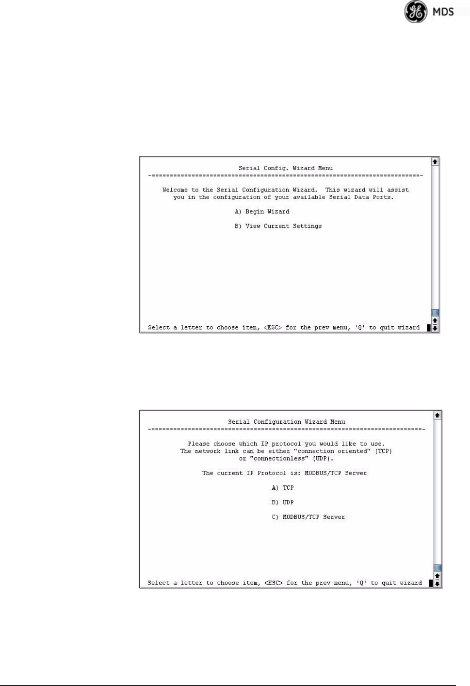
05-4446A01, Rev. E Mercury Reference Manual 89
3.6.2 Menu Selections
Connect a PC to the transceiver as described in STEP 3: CONNECT PC
TO THE TRANSCEIVER section on Page 25, and access the embedded
management system. Follow the steps below to proceed with
Modbus/TCP configuration.
1. From the Serial Configuration Wizard opening screen (Figure 3-53
on Page 89), select A to begin the wizard.
Invisible place holder
Figure 3-53. Configuration Wizard Opening Screen
2. Choose the IP protocol you wish to use (TCP, UDP, or Mod-
bus/TCP) by selecting the appropriate letter from the menu.
Figure 3-54. IP Protocol Selection Screen
3. On the next screen (Figure 3-55 on Page 90), choose the listening
port you wish to use for the Modbus/TCP server. The default is port
502. Press N to continue.
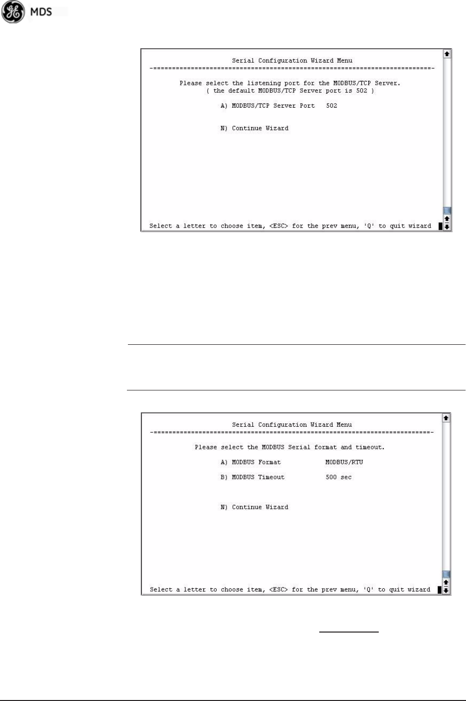
90 Mercury Reference Manual 05-4446A01, Rev. E
Figure 3-55. Modbus/TCP Server Listening Port
4. On the next screen (Figure 3-56), press A to change the Modbus
serial format, then press the space bar to toggle between the avail-
able formats (MODBUS/RTU or MODBUS/ASCII). Press B to enter the
Modbus serial timeout value in milliseconds. Press N to continue the
wizard.
NOTE: The only difference between Modbus/RTU and
Modbus/ASCII is the form of the framing sequence, error
check pattern, and address interpretation.
Figure 3-56. Choose Modbus Serial Format and Timeout Value
Note: Modbus Timeout setting is in milliseconds, not seconds
as displayed in the example above.
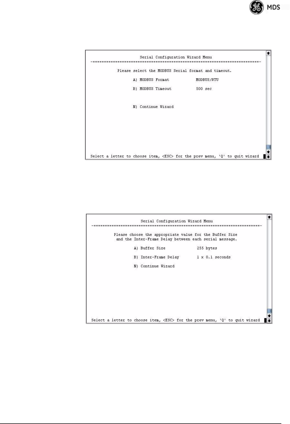
05-4446A01, Rev. E Mercury Reference Manual 91
5. When the next screen appears (Figure 3-57), press A to select the
desired data baud rate and B to select the data byte format. Press N to
continue.
Figure 3-57. Select Data Baud Rate and Byte Format
6. The screen shown in Figure 3-58 appears next. Press A to select the
Buffer Size of message packets, and B to select the Inter-Frame
Delay. Press N to continue with the wizard.
Invisible place holder
Figure 3-58. Buffer Size and Inter-Frame Delay Values
7. On the next screen (Figure 3-59 on Page 92), select A and use the
spacebar to enable the serial port for data communication. Press N to
continue the wizard.
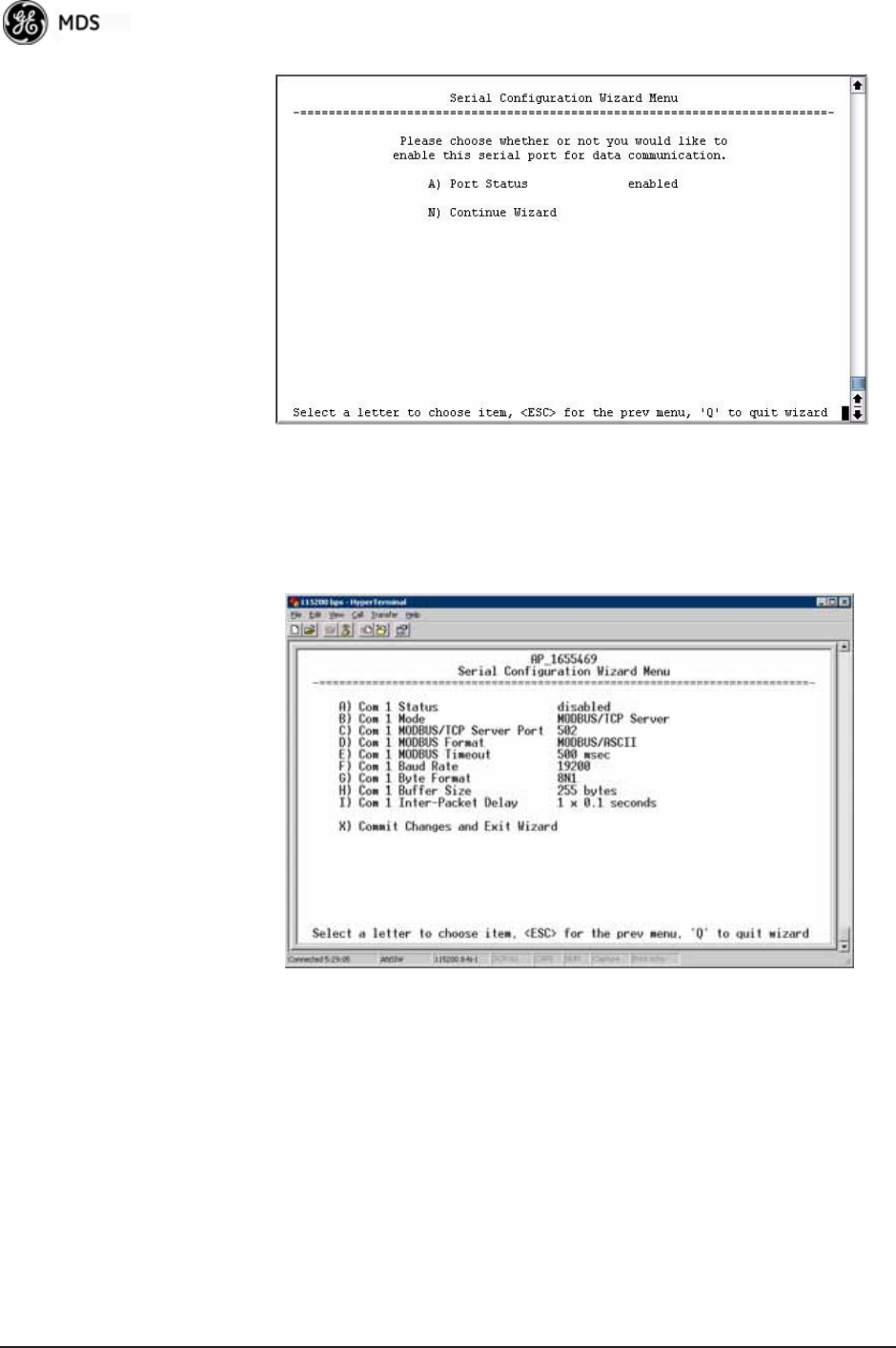
92 Mercury Reference Manual 05-4446A01, Rev. E
Invisible place holder
Figure 3-59. Serial Port Status Screen
8. Review all settings on the summary screen shown in Figure 3-60. If
all settings are correct, press X to confirm and exit the wizard. If not,
select the letter of the item(s) you wish to change.
Invisible place holder
Figure 3-60. Serial ConfigurationSummary Screen
This completes the menu selections for Modbus/TCP operation.
3.7 SECURITY CONFIGURATION
MENU
The transceiver’s security features are grouped into four major catego-
ries and are accessible from the Security Configuration Menu (see
Figure 3-61). These categories are:
Device Security—Contains settings for controlling access to the radio
itself for configuration and management.
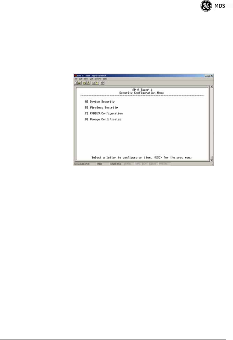
05-4446A01, Rev. E Mercury Reference Manual 93
Wireless Security—Controls how and when radios communicate with
each other, as well as how data traffic is handled.
RADIUS Configuration—Deals with IEEE 802.1x device authentication
and authorization using a central server.
Manage Certificates (Remote only)—Allows setting of certificate types,
download paths, and TFTP parameters.
Invisible place holder
Figure 3-61. Security Configuration Menu
Selecting any of the Security Configuration Menu items opens a sub-
menu where you can view or change settings. Examples of these screens
and more detailed descriptions of their contents are provided below.
3.7.1 Device Security Menu
The Device Security Menu (Figure 3-62) controls how the radios can be
accessed either locally or remotely for configuration and management.
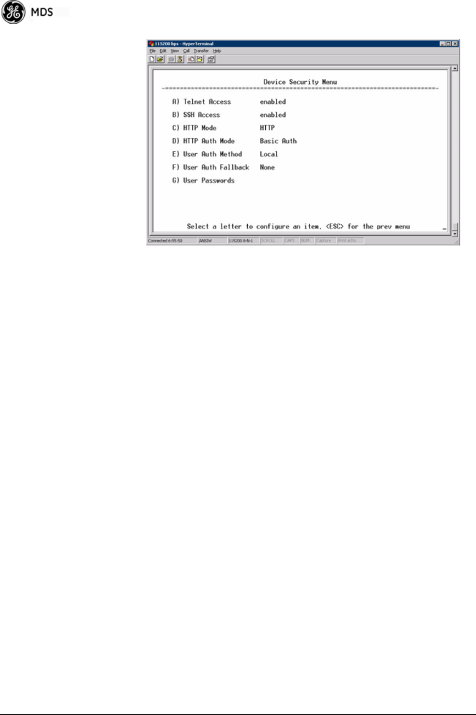
94 Mercury Reference Manual 05-4446A01, Rev. E
Invisible place holder
Figure 3-62. Device Security Menu
•Telnet Access—Controls Telnet access to the transceiver’s man-
agement system. [enabled, disabled; enabled]
•SSH Access—Controls access to the Secure Shell (SSH) server.
[enabled, disabled; enabled]
•HTTP Mode—Controls access to the transceiver’s management
system via the web server. [disabled, HTTP, HTTPS; HTTP]
•HTTP Auth Mode—Selects the mode used for authenticating a web
user. [Basic Auth, MD5 Digest; Basic Auth]
•User Auth Method—View/set the method of authentication for
users. [Local, Radius; Local]
•User Auth Fallback—View/set method of authentication to use if
the RADIUS server is unavailable. [None, Local; None]
•User Passwords—Allows changing of Administrative and Guest
passwords. When selected, a new screen appears (Figure 3-63
on Page 95).
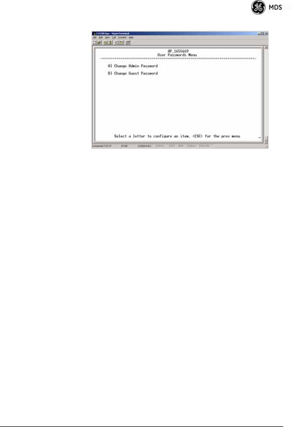
05-4446A01, Rev. E Mercury Reference Manual 95
User Passwords Menu Invisible place holder
Figure 3-63. User Passwords Menu
To change the Administrator or Guest password, select the appropriate
menu item (A or B). A flashing cursor appears to the right. From here,
type the new password, which can be any alpha-numeric string up to 13
characters long. The change is asserted when you press the Return key.
•Change Admin Password—Allows you to set a new password.
[any alpha-numeric string up to 13 characters; admin]
•Change Guest Password—Allows you to set a new password.
[any alpha-numeric string up to 13 characters; guest]
TIP: For enhanced security, consider using misspelled words, a combi-
nation of letters and numbers, and a combination of upper and
lower case letters. Also, the more characters used (up to 13), the
more secure the password. These strategies help protect against
sophisticated hackers who use a database of common words (for
example, dictionary attacks) to determine a password.
3.7.2 Wireless Security Menu
The features in the Wireless Security menu (Figure 3-64 on Page 96)
control the communication of data across the wireless link. You can
authenticate the radios locally via a list of authorized radios, or remotely
via a centralized IEEE 802.1x device authentication server. This server
provides a centralized authentication mechanism based on standards.

96 Mercury Reference Manual 05-4446A01, Rev. E
Invisible place holder
Figure 3-64. Wireless Security Menu
•Device Auth Mode—View/set the device’s authentication method.
[None, Local, IEEE 802.1X; None]
•Data Encryption—Controls the over-the-air payload data’s
AES-128 bit encryption. [enable, disable; disabled]
•Encryption Phrase—View/set the phrase used to generate encryp-
tion keys when encrypting over-the-air payload.
[any alpha-numeric string of 8 to 15 characters; <empty>]
•Max Remotes (AP only)—The maximum number of remotes an
AP can associate with.
•Approved Remotes (AP only)—Launches a submenu where you
can view, add, or delete approved Remotes. (See Figure 3-65.)
Approved Remotes
Submenu Setting the Device Auth Mode to Local forces an AP to check the Approved
Remotes List before establishing a radio link. A Remote must be in the
list before the AP associates and grants authorization. Before enabling
this option, at least one entry must already exist in the View Approved
Remotes list.

05-4446A01, Rev. E Mercury Reference Manual 97
Invisible place holder
Figure 3-65. Approved Remotes Submenu
•Add Remote—Enter the MAC address of Remote.
[Any valid 6-digit hexadecimal MAC address; 00:00:00:00:00:00]
•Delete Remote—Enter the MAC address of Remote. For security
purposes, you should delete a stolen or deprovisioned radio
from this list.
•Add Associated Remotes—Add all currently associated remotes to
the approved remote list. Alternatively, you can enter each
Remote MAC manually.
•Delete All Remotes—Remove (complete purge) all Remotes from
current list.
•View Approved Remotes—Listing of approved Remotes by MAC
address. These radios are authorized to join this AP. If a Remote
is not in this list, it cannot associate with this AP.
3.7.3 IEEE 802.1x Device Authentication
This section covers the configuration needed for the radios to access the
IEEE 802.1x device authentication server, which provides Device Level
Security and for Wireless Access Security. GE MDS does not provide
the server software.
Operation of Device Authentication
Device authentication forces the radio to authenticate before allowing
user traffic to traverse the wireless network. When Device Security is
configured to use IEEE 802.1x as the Authentication Method, Remote
radios need three types of certificates: public (client), private, and root
(Certificate Authority). These files are unique to each Remote radio and
must first be created at the server and then installed into each unit via
TFTP. The certificate files must be in DER format.
Device authentication uses the serial number of each radio as the
Common Name (CN) in its certificate and in its RADIUS identity field.

98 Mercury Reference Manual 05-4446A01, Rev. E
Each Access Point and Remote radio must be identified/recognized by
the device authentication server through the Common Name (Serial
number) and IP address entries.
NOTE: Consult your network administrator for assistance in configu-
ration, or for help with other issues that may arise.
To activate device authentication, select Device Auth Method and set
RADIUS as the active mode. The behavior of this setting differs
depending on whether it is implemented on an Access Point or a Remote
transceiver. An explanation of these behaviors is given below:
Access Point: When Device Auth Method is set to RADIUS, the AP disasso-
ciates all associated Remotes and waits for the device authentication
server to authenticate the Remotes before allowing data from them to
pass. When approval is received from the authentication server, data
from the Remote passes.
Remote: When Device Auth Method is set to RADIUS, the Remote halts any
data it is passing, and requests Authentication from the device authenti-
cation server. If accepted, data is transmitted.
Operation of User Authentication
User Authentication controls authentication of users who can manage
the device. This is in contrast to Device Authentication (above), which
authenticates devices that can participate in the data network. When user
authentication is set to Local or RADIUS, you must enter a valid user name
and password before you can manage the radio. In RADIUS mode, both
of these fields can be up to 40 characters long. In Local mode the user
name is admin and the password can be up to 13 characters long.
When set to RADIUS, all logins to the local configuration services must
be authenticated via the device authentication server, including Telnet
and SSH (Secure Shell) sessions. Authentication must be accepted
before access to the radio menu is granted.
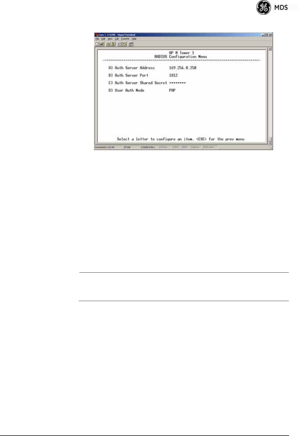
05-4446A01, Rev. E Mercury Reference Manual 99
RADIUS Configuration Menu Invisible place holder
Figure 3-66. Radius Configuration Menu
•Auth Server Address—The IP address of the authentication
server. [any valid IP address; 0.0.0.0]
•Auth Server Port—The UDP Port of the authentication server.
[1812, 1645, 1812]
•Auth Server Shared Secret—User authentication and Device
authentication require a common shared secret to complete an
authentication transaction. This entry must match the string
used to configure the appropriate files on the authentication
server.
[<empty>; any alpha-numeric string up to 16 characters]
•User Auth Mode—RADIUS Authentication algorithm.
[PAP, CHAP, EAP; PAP]
NOTE: CHAP is a more secure algorithm than PAP. PAP may display
the login password in log files at the authentication server
while CHAP will encrypt this information.
3.7.4 Manage Certificates
Use Certificate generation software to generate certificate files, then
install these files into each Remote unit using TFTP. This is done using
the Manage Certificates Menu (Figure 3-67 on Page 100).
The certificate files must be in DER format. The Common Name (CN)
field in the public certificate file must match the serial number of the
unit it is installed on.
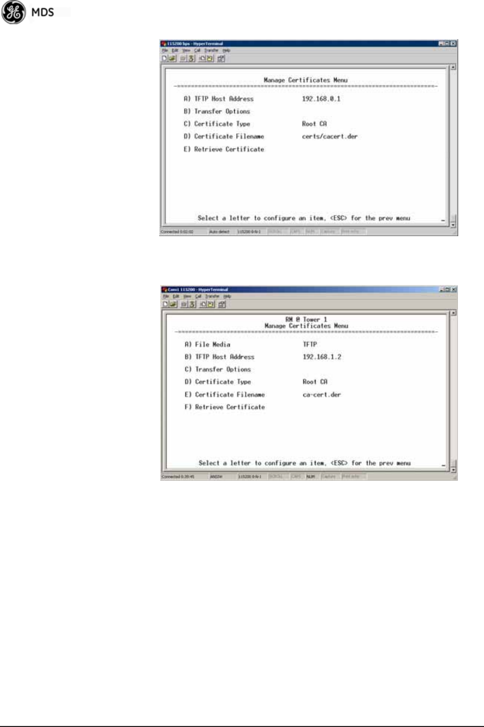
100 Mercury Reference Manual 05-4446A01, Rev. E
Invisible place holder
Figure 3-67. Manage Certificates Menu
Invisible place holder
Figure 3-68. Manage Certificates Menu, TFTP Mode
(Option Set Remote only)
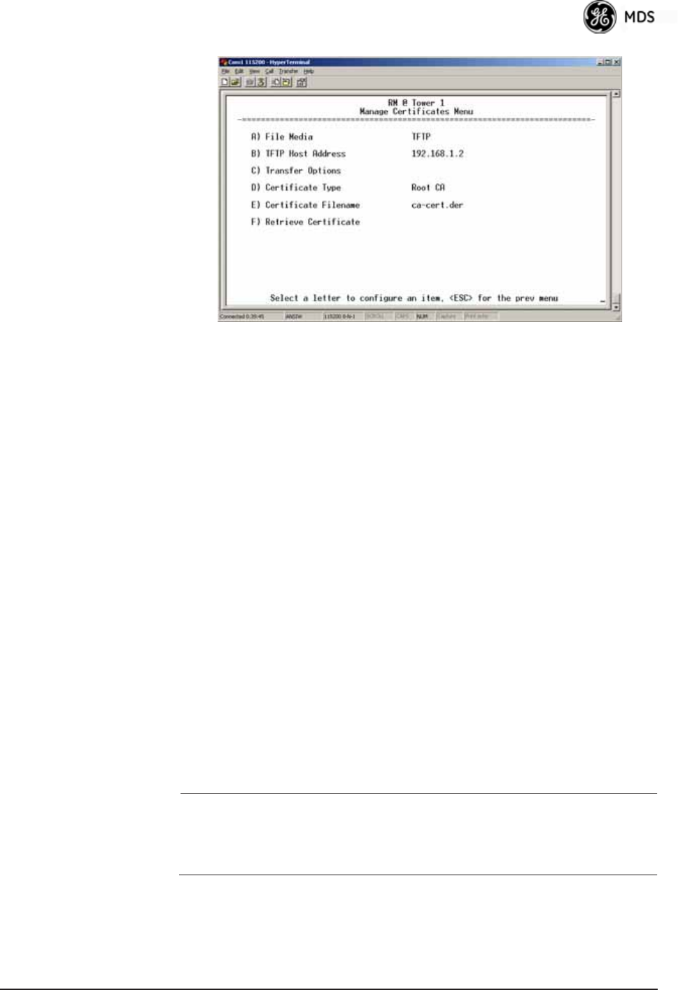
05-4446A01, Rev. E Mercury Reference Manual 101
Invisible place holder
Figure 3-69. Manage Certificates Menu, USB Mode
(Option Set Remote only)
•File Media—A selection of methods for transferring files to and
from the radio. On firmware version 3.0 radios, the options are
TFTP and USB.
•TFTP Host Address—(Telnet/Terminal only)—IP address of the com-
puter on which the TFTP server resides. This same IP address is
used in other screens/functions (reprogramming, logging, etc.).
Changing it here also changes it for other screens/functions.
[Any valid IP address; 127.0.0.1].
•Transfer Options—A menu for configuring the TFTP transfer.
(See Figure 3-70 on Page 102.)
Three certificate files (Root CA, Client, and Private Key) must be
present in each of the Remote radios. Use the commands described
below to install these files into each Remote radio:
•Certificate Type—Selects one of the three certificate file types
mentioned above. [Root CA, Client, Private Key; Root CA]
•Certificate Filename—Specifies the software path and filename
for downloading certificates.
•Retrieve Certificate—Initiates the retrieval of the certificate file
from the storage location. A successful installation issues a Com-
plete status message.
NOTE: It is imperative that the three certificate files are installed
correctly into the Remote radio, in their respective file types.
If they are not, the Remote is un-authenticated for data traffic.
Consult your network administrator for more information.

102 Mercury Reference Manual 05-4446A01, Rev. E
Invisible place holder
Figure 3-70. Transfer Options Menu
•TFTP Timeout—The time the client radio will wait for a response
from the server before ending the transfer.
•TFTP Block Size—The amount of data sent in each TFTP packet.
3.8 REDUNDANCY CONFIGURATION
(AP ONLY)
For operation in protected (redundant) mode, an AP must be in a Pack-
aged P23 enclosure with a backup radio. See MDS publication
05-4161A01 for details. This manual is available under the Downloads
tab at www.GEmds.com.
The Redundancy Configuration Menu (Figure 3-71) is where you
enable/disable redundancy operation and define the triggers that will
cause a switchover.
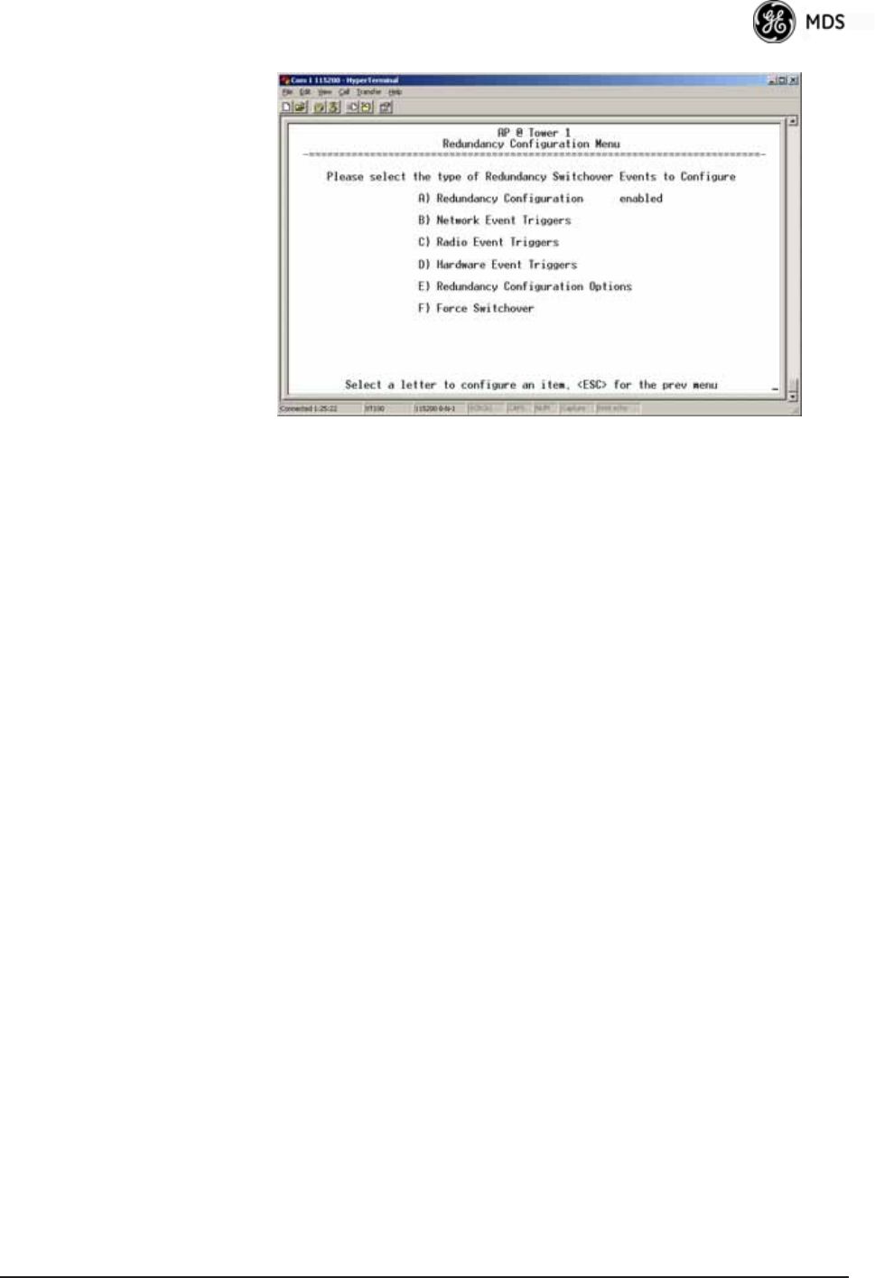
05-4446A01, Rev. E Mercury Reference Manual 103
Invisible place holder
Figure 3-71. Redundancy Configuration Menu (AP Only)
•Redundancy Configuration—Enable/disable redundancy switcho-
ver for AP. [enabled, disabled; disabled]
•Network Event Triggers—This selection opens a submenu
(Figure 3-72 on Page 104) where you can set/view the trigger
status for Network Events.
•Radio Event Triggers—This selection opens a submenu
(Figure 3-73 on Page 104) where you can set/view the trigger
status for Radio Events, such as a loss of associated Remotes or
excessive packet errors.
•Hardware Event Triggers—This selection opens a submenu
(Figure 3-74 on Page 105) where you can set/view the trigger
status for initialization/hardware errors.
•Redundancy Configuration Options—This selection opens a sub-
menu (Figure 3-75 on Page 105) where you can set the thresh-
old criteria for declaring an error event.
•Force Switchover—Selecting this option forces a manual (user
initiated) switchover to the backup AP. The “challenge ques-
tion” Are you sure? (y/n) is presented to avoid an unintended
switchover. To invoke the change, press the letter y followed by
the Enter key.
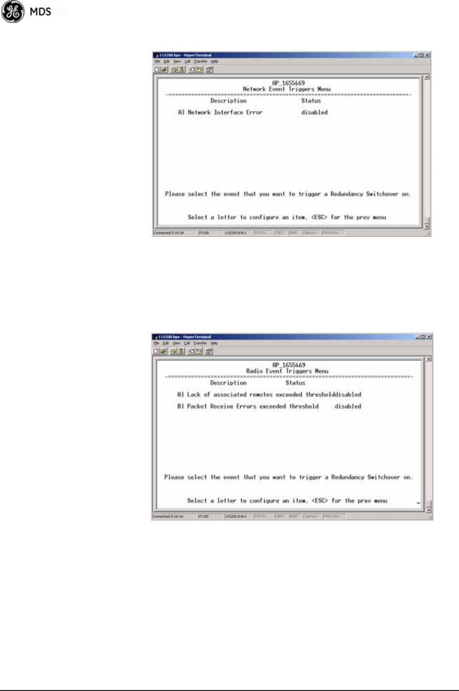
104 Mercury Reference Manual 05-4446A01, Rev. E
Network Event Triggers Menu Invisible place holder
Figure 3-72. Network Events Triggers Menu
•Network Interface Error—This setting determines whether or not a
network interface error will cause redundancy switchover.
[enabled, disabled; disabled]
Radio Event Triggers Invisible place holder
Figure 3-73. Radio Event Triggers
•Lack of associated remotes exceeded threshold—This setting deter-
mines whether or not a switchover occurs when a lack of asso-
ciated Remote units exceeds the time period set in Figure 3-76
on Page 106. [enabled, disabled; disabled]
•Packet Receive Errors exceeded threshold—This setting determines
whether or not a switchover occurs when the number of Packet
Receive errors exceeds the number set in Figure 3-77 on
Page 106. [enabled, disabled; disabled]
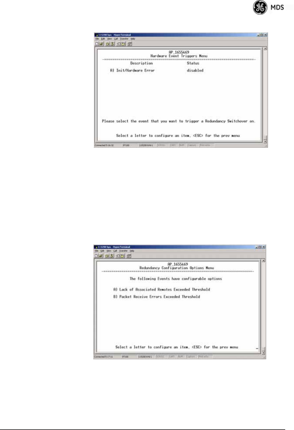
05-4446A01, Rev. E Mercury Reference Manual 105
Hardware Event Triggers Invisible place holder
Figure 3-74. Hardware Event Triggers
•Init/Hardware Error—This setting determines whether or not an
initialization or hardware error results in a redundancy switcho-
ver. [enabled, disabled; disabled]
Redundancy Configuration Options Menu
Use this menu (Figure 3-75) to set the thresholds for the Lack of Asso-
ciated Remotes and Packet Receive Errors. Selecting either item opens
a submenu where you can view or change settings.
Invisible place holder
Figure 3-75. Redundancy Configuration Options Menu
•Lack of Associated Remotes Exceeded Threshold—This selection
opens a submenu (Figure 3-76) where you can view or change
the time period allowed for a lack of associated Remotes.
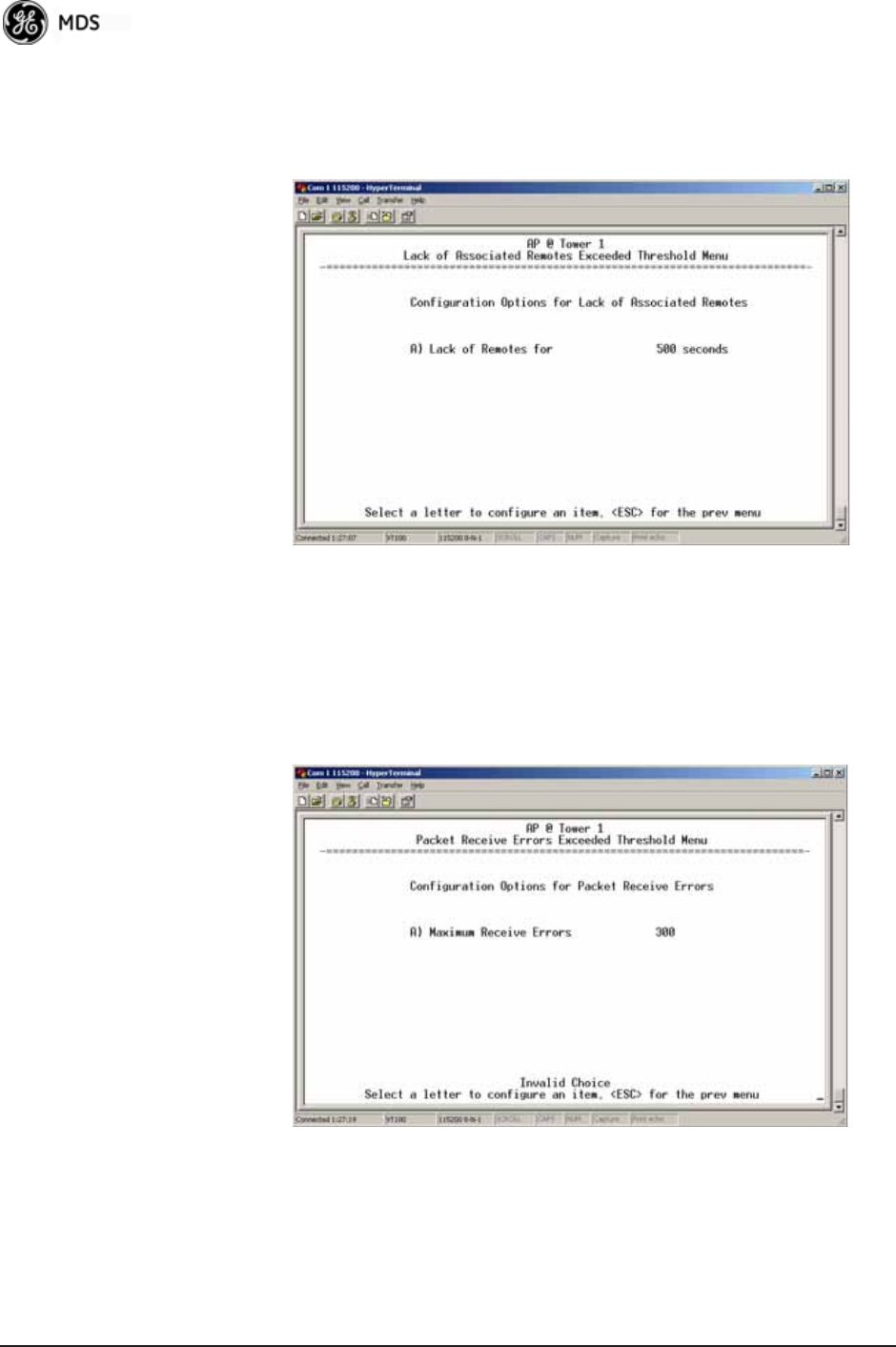
106 Mercury Reference Manual 05-4446A01, Rev. E
•Packet Receive Errors Exceeded Threshold—This selection opens a
submenu (Figure 3-77 on Page 106) where you can view or
change the maximum allowable number of receive errors.
Lack of Associated
Remotes Exceeded
Threshold Menu
Invisible place holder
Figure 3-76. Lack of Associated Remotes
Exceeded Threshold Menu
•Lack of Remotes for—Select this item to change the time setting
(in seconds) for a lack of associated Remotes. When there are
no associated Remotes for a period exceeding this time, a redun-
dancy switchover occurs. [60-500; 500]
Packet Receive
Errors Exceeded
Threshold Menu
Invisible place holder
Figure 3-77. Packet Receive Errors Exceeded Threshold Menu
•Maximum Receive Errors—Select this item to change the maxi-
mum allowable number of receive errors. When the number of
errors exceeds this number, a redundancy switchover occurs.
[0-1000; 500]
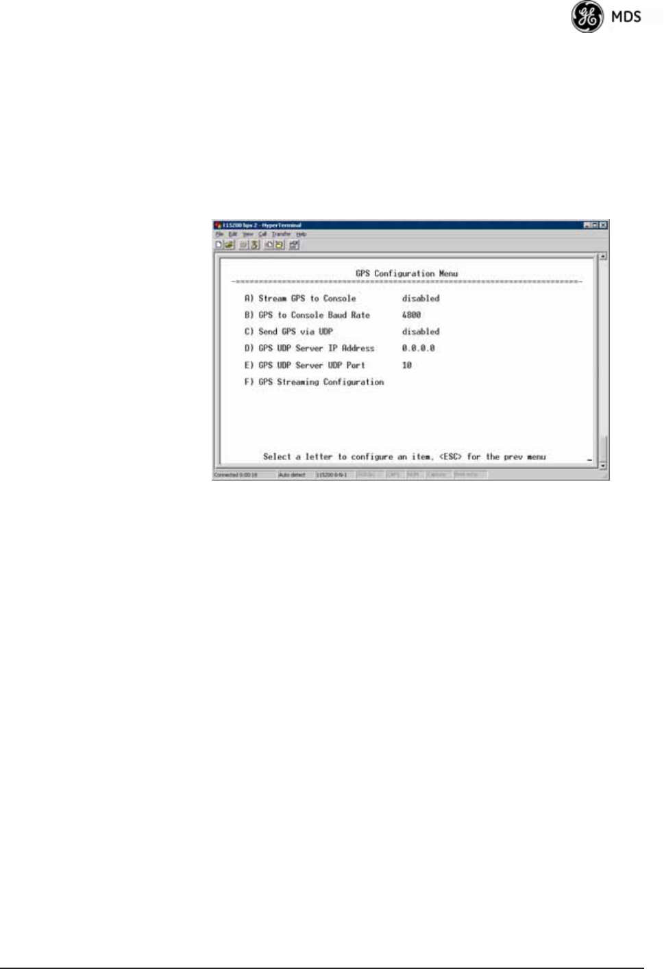
05-4446A01, Rev. E Mercury Reference Manual 107
3.9 GPS CONFIGURATION (REMOTE
ONLY)
This menu allows you to view or set important parameters for the
built-in Global Positioning System (GPS) receiver in the Mercury
Remote. Mercury 3650 Remote units do not have or require GPS func-
tionality. Details about the NMEA sentences generated by the GE MDS
Mercury can be found at http://www.nps.gov/gis/gps/NMEA_sentences.html.
Invisible place holder
Figure 3-78. GPS Configuration Menu (Remote Only)
•Stream GPS to Console—Used to enable/disable streaming of
GPS NMEA data to the console port (COM1). Baud rate is 4800
baud when Stream GPS to console is enabled.
[enabled, disabled; disabled]
•GPS to Console Baud Rate—The serial baud rate when GPS
streaming is enabled.
•Send GPS via UDP—Used to enable/disable sending GPS NMEA
data to a server via UDP. [enabled, disabled; disabled]
•GPS UDP Server IP Address—Specify the destination address for
GPS NMEA UDP packets. [any valid IP address; 0.0.0.0]
•GPS UDP Server UDP Port—Destination UDP port for GPS
NMEA UDP packets. [valid UDP port number; 0]
•GPS Streaming Configuration—A submenu for setting GPS
NMEA outputs. (See Figure 3-79 on Page 108.)

108 Mercury Reference Manual 05-4446A01, Rev. E
Invisible place holder
Figure 3-79. GPS Streaming Configuration Menu
•GGA Polling—Seconds between GGA string outputs, the satellite
fix information.
•GLL Polling—Seconds between GLL string outputs, the latitude
and longitude information.
•GSA Polling—Seconds between GSA string outputs, the overall
satellite data.
•GSV Polling—Seconds between GSV string outputs, the detailed
satellite data.
•RMC Polling—Seconds between RMC string outputs, the recom-
mended minimum data.
•VTG Polling—Seconds between VTG string outputs, the vector
track and speed over ground.
•MSS Polling—Seconds between MSS string outputs, the beacon
receiver status information.
•ZDA Polling—Seconds between ZDA string outputs, data, and
time.
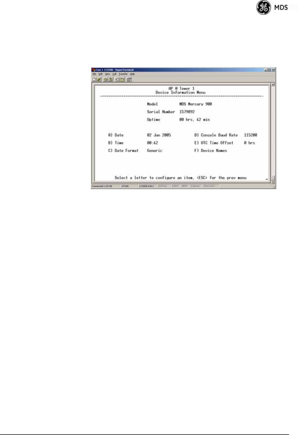
05-4446A01, Rev. E Mercury Reference Manual 109
3.10 DEVICE INFORMATION MENU
Figure 3-80 shows the menu that displays basic administrative data on
the unit to which you are connected. It also provides access to user-spe-
cific parameters such as date/time settings and device names.
Figure 3-80. Device Information Menu
•Model (Display only)
•Serial Number (Display only)
•Uptime (Display only)—Elapsed time since boot-up.
•Date—Current date being used for the transceiver logs. User-set-
able. (Value lost with power failure if SNTP [Simple Network
Time Protocol] server not accessible.)
•Time—Current time of day. User-setable.
Setting: HH:MM:SS
(Value lost with power failure if SNTP server not accessible.)
•Date Format—Select presentation format:
• Generic = dd Mmm yyyy
• European = dd-mm-yyyy
• US = mm-dd-yyyy
•Console Baud Rate—Used to set/display data communications
rate (in bits-per-second) between a connected console terminal
and the radio. [115200]
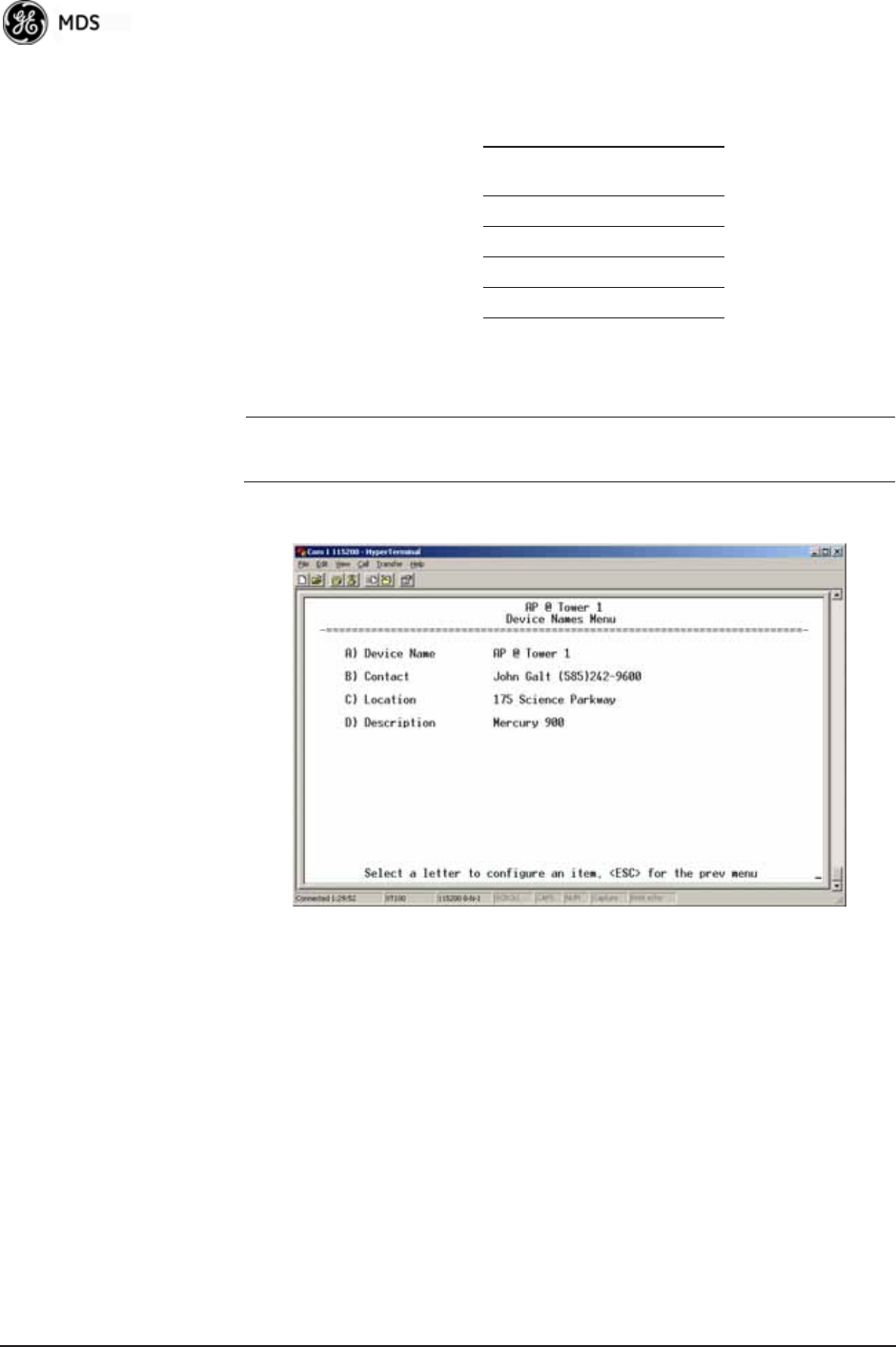
110 Mercury Reference Manual 05-4446A01, Rev. E
•UTC Time Offset—Set/view the number of hours difference
between your local clock time and Universal Coordinated Time.
Offsets for U.S. times zones are shown in the chart below.
•Device Names—Fields used at user’s discretion for general
administrative purposes. The Device Name field is shown on all
menu screen headings. (See Figure 3-81 on Page 110)
NOTE: The transceivers do not save time and date information when
power is removed.
Device Names Menu
Figure 3-81. Device Names Menu
•Device Name—Used by the transceiver as the “Realm” name
for network login (web browser only) and menu headings.
•Contact—User defined; appears on this screen only.
•Location—User defined; appears on this screen only.
•Description—User defined; appears on this screen only.
3.11 PERFORMANCE INFORMATION
MENU
The Performance Information Menu (Figure 3-82 on Page 111) is the
entry point for a series of submenus where you can evaluate transceiver
operating status and network performance. You can use this menu as an
Time Zone
(U.S.)
UTC Offset
(Hours)
PST -8
MST -7
CST -6
EST -5
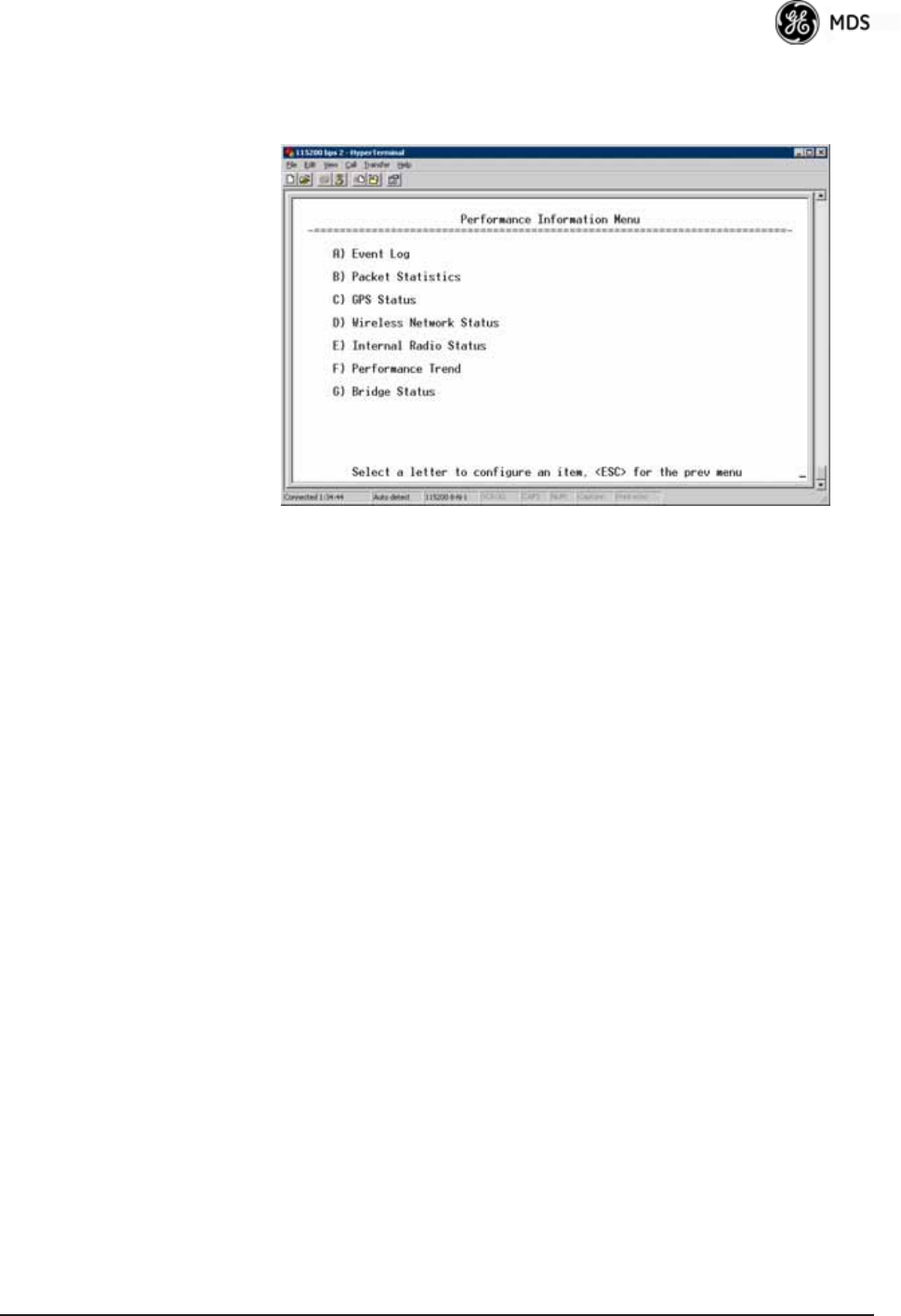
05-4446A01, Rev. E Mercury Reference Manual 111
important troubleshooting tool, or for evaluating changes made to the
network configuration or equipment.
Invisible place holder
Figure 3-82. Performance Information Menu
•Event Log—Access this menu for managing the unit’s opera-
tional activities log. (See Figure 3-85 on Page 113 for details.)
•Packet Statistics—Multiple radio and network operating statis-
tics. (See Figure 3-87 on Page 115 for details.)
•GPS Status—Shows satellite fix status, number of satellites
being received, and unit location data. (See Figure 3-88 on
Page 116 for details.)
•Wireless Network Status—Current AP association state and MAC
address. (See Figure 3-90 on Page 118 for details.)
•Internal Radio Status (Remote Only)—Shows connection status,
RF parameters, and total FEC count for the unit. (See
Figure 3-95 on Page 120 for details.)
•Performance Trend (Remote Only)—Launches a continuously
updated list of performance parameters (RSSI, Signal-to-Noise
Ratio, Transmit Power, Latitude, Longitude, Connection Status,
and FEC Blocks). (See Figure 3-83 on Page 112.)
•Bridge Status—Displays the network bridge status. (See
Figure 3-84 on Page 112.)
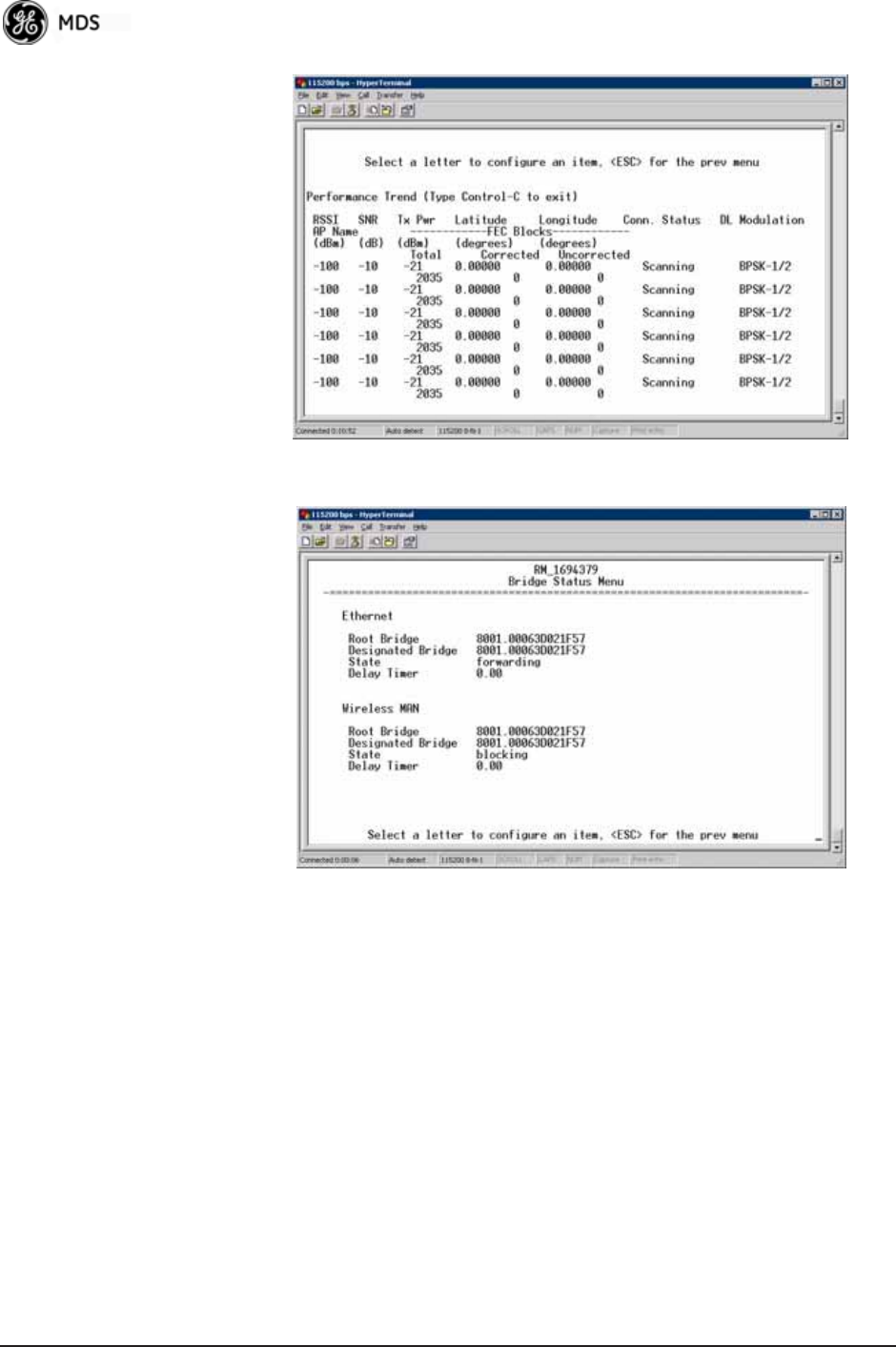
112 Mercury Reference Manual 05-4446A01, Rev. E
Invisible place holder
Figure 3-83. Performance Trend Screen
Invisible place holder
Figure 3-84. Bridge Status Menu
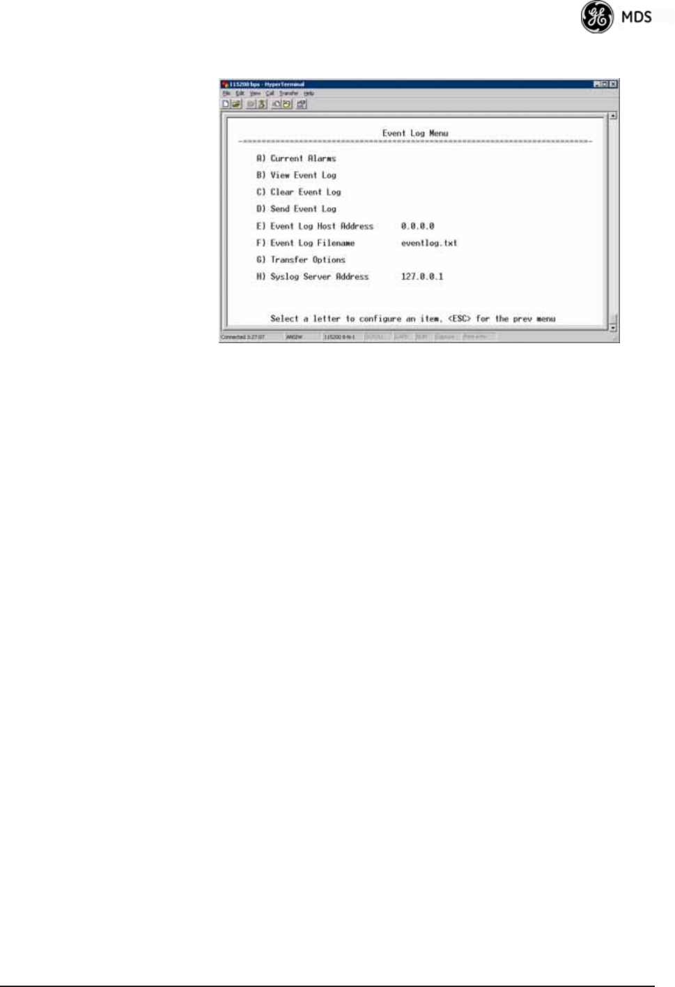
05-4446A01, Rev. E Mercury Reference Manual 113
Event Log Menu Invisible place holder
Figure 3-85. Event Log Menu
•Current Alarms—Shows active alarms (if any) reported by the
transceiver.
•View Event Log—Displays a log of radio events arranged by event
number, date, and time. (Example shown in Figure 3-86 on
Page 114).
•Clear Event Log—Erases all previously logged events.
•Send Event Log—Sends the event log to the server. You must
answer the challenge question Send File? y/n before the request
proceeds.
•Event Log Host Address—Set/display the IP address of the TFTP
server. [any valid IP address; 0.0.0.0]
•Event Log Filename—Set/display the name of the event log file on
the TFTP server. [any valid filename; eventlog.txt]
•Transfer Options—A menu for configuring the TFTP transfer.
•Syslog Server Address—Use this selection to set or view the IP
address of the Syslog server. Syslog is a standardized protocol
for sending IP log data across a network. Low cost (or even free)
Syslog downloads are available online by searching for the term
“Syslog Server.” [any valid IP address; 0.0.0.0]

114 Mercury Reference Manual 05-4446A01, Rev. E
View Event Log
Menu Invisible place holder
Figure 3-86. View Event Log Menu
The transceiver’s microprocessor monitors many operational parame-
ters and logs them. Events are classified into four levels of importance,
which are described in Table 3-8. Some of these events result from a
condition that prevents normal operation of the unit. These are “critical”
events that cause the unit to enter an “alarmed” state and the PWR LED
to blink until the condition is corrected. All events are stored in the
Event Log..
Time and Date The events stored in the Event Log are time-stamped using the time and
date of the locally connected device. The Access Point obtains the time
and date from a Time Server. This server is typically a standard Win-
dows PC server SNTP application. In the absence of the SNTP services,
the user must manually enter time and date information at the Access
Point. (See “DEVICE INFORMATION MENU” on Page 109 for SNTP
server identification.) The manually set time and date clock relies on the
unit’s primary power. A loss of power resets the clock to 02 Jan 2005 but
does not affect previously stored error events.
Packet Statistics Menu
The transceivers maintain running counters of different categories of
events in the Ethernet protocol. The Packet Statistics refer to each
Ethernet interface from the perspective of the radio.
Table 3-8. Event Classifications
Level Description/Impact
Informational Normal operating activities
Minor Does not affect unit operation
Major Degraded unit performance but
still capable of operation
Critical Prevents the unit from operating
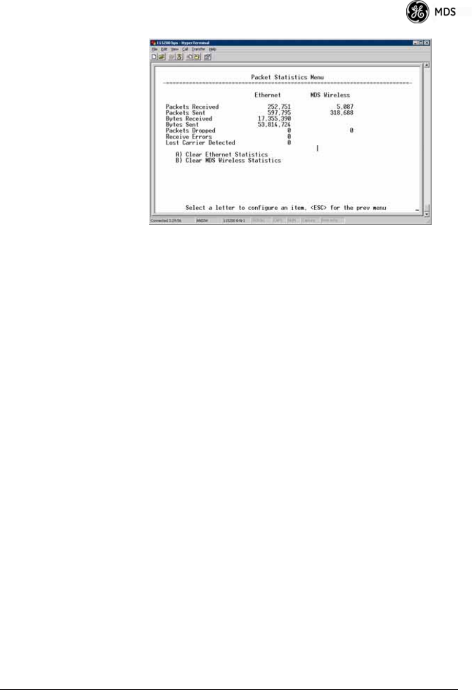
05-4446A01, Rev. E Mercury Reference Manual 115
Invisible place holder
Figure 3-87. Packet Statistics Menu
•Packets Received—Data packets received by this unit.
•Packets Sent—Data packets sent by this unit.
•Bytes Received—Data bytes received by this unit.
•Bytes Sent—Data bytes sent by this unit.
•Packets Dropped—To-be-transmitted packets dropped because
of a lack of buffers in the outbound queue.
•Receive Errors—Packets that do not pass CRC. This may be due
to transmissions corrupted by RF interference, Ethernet colli-
sions, or degradation. If significant Ethernet Receive Errors are
observed, check the quality of your Ethernet cabling and con-
nectors, or that you do not have cable lengths exceeding the
specification limits.
•Lost Carrier Detected—This parameter reports how many times
the wired Ethernet connection has lost link.
•Clear Ethernet Statistics—Resets the statistics counter. You must
answer the challenge question Send File? y/n before the request
proceeds.
•Clear MDS Wireless Statistics—Resets the statistics counter. You
must answer the challenge question Send File? y/n before the
request proceeds.
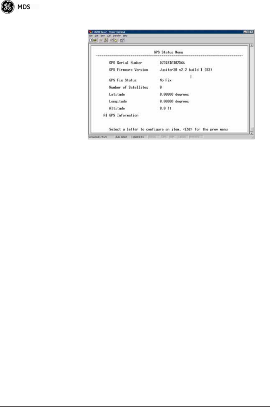
116 Mercury Reference Manual 05-4446A01, Rev. E
GPS Status Menu Invisible place holder
Figure 3-88. GPS Status Menu
•GPS Serial Number—The serial number of the GPS unit in the
radio.
•GPS Firmware Version—The firmware version running on the
GPS chip.
•Satellite Fix Status—Indicates whether or not the unit has
achieved signal lock with the minimum required number of
GPS satellites. The transceiver requires a fix on five satellites to
achieve Precise Positioning Service (PPS) and four to maintain
PPS. [No Fix, Fix]
•Number of Satellites—Shows the number of GPS satellites
received by the transceiver. Although there are typically 24
active GPS satellites orbiting the Earth twice a day, only a sub-
set of these is “visible” to a receiver at a given location. A good
signal provides information from six to ten satellites.
•Latitude—Shows the transceiver’s latitudinal location (in
degrees), based on GPS data received from the satellites.
•Longitude—Shows the transceiver’s longitudinal location (in
degrees), based on GPS data received from the satellites.
•Altitude—Shows the transceiver’s altitude above sea level (in
feet), based on GPS data received from the satellites.
•GPS Information—Shows data about the individual satellites
being received, including the Pseudo-Random Noise (PRN)
code (a unique bit stream for each satellite), the satellite’s ele-
vation (in degrees), azimuth (in degrees), and the sig-
nal-to-noise ratio of the carrier signal (SNR). Figure 3-89 on
Page 117 shows a layout example for this screen.
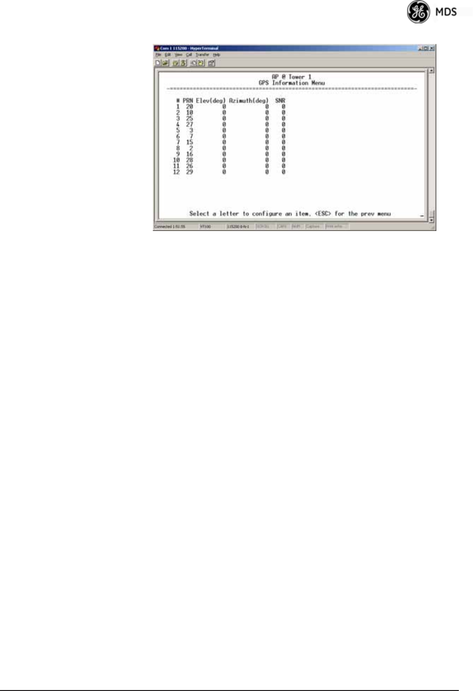
05-4446A01, Rev. E Mercury Reference Manual 117
GPS Information
Menu Invisible place holder
Figure 3-89. GPS Information Menu
Wireless Network Status Menu
The Wireless Network Status screen provides information on a key
operating process of the transceiver—the association of the Remote with
the Access Point. The following is a description of how this process
takes place and is monitored by the menu system.
The Transceivers
Association Process If the Access Point and Remote are configured for single channel oper-
ation, the Remote monitors the channel for Access Point transmissions.
The Remote synchronizes its power, timing, and frequency to the
Access Point, then requests access to the network. The Access Point and
Remote check each other’s authorization and authentication according
to the configuration of the Device Authorization and Encryption Enable
parameters, and the Network Name parameter. The Remote is then associ-
ated.
If the Access Point and Remote are configured for frequency hopping,
the Remote hops with the Access Point according to Access Point’s con-
figuration. Once the Remote is hopping in sync with the Access Point,
the rest of the association process is the same as for single channel oper-
ation.
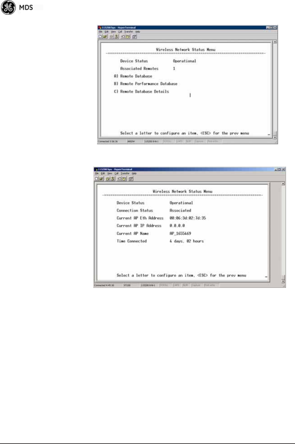
118 Mercury Reference Manual 05-4446A01, Rev. E
Invisible place holder
Figure 3-90. Wireless Network Status Menu (AP)
Invisible place holder
Figure 3-91. Wireless Network Status Menu (Remote)
•Device Status—Displays the overall operating condition of the
transceiver. [Operational, Alarmed]
•Associated Remotes (AP Only)—Shows the number of Remote
transceivers currently associated with the AP.
•Remote Database (AP Only)—Displays a submenu where associ-
ated Remotes are listed in table form according to their number,
operational state, MAC address, IP address, and name (if
assigned). (See Figure 3-92 on Page 119.)
•Remote Performance Database (AP Only)—Displays a submenu
where associated Remote performance data is listed in table
form. Remotes are presented according to their number, MAC
address, RSSI, SNR, modulation type, and FEC total. (See
Figure 3-93 on Page 119.)
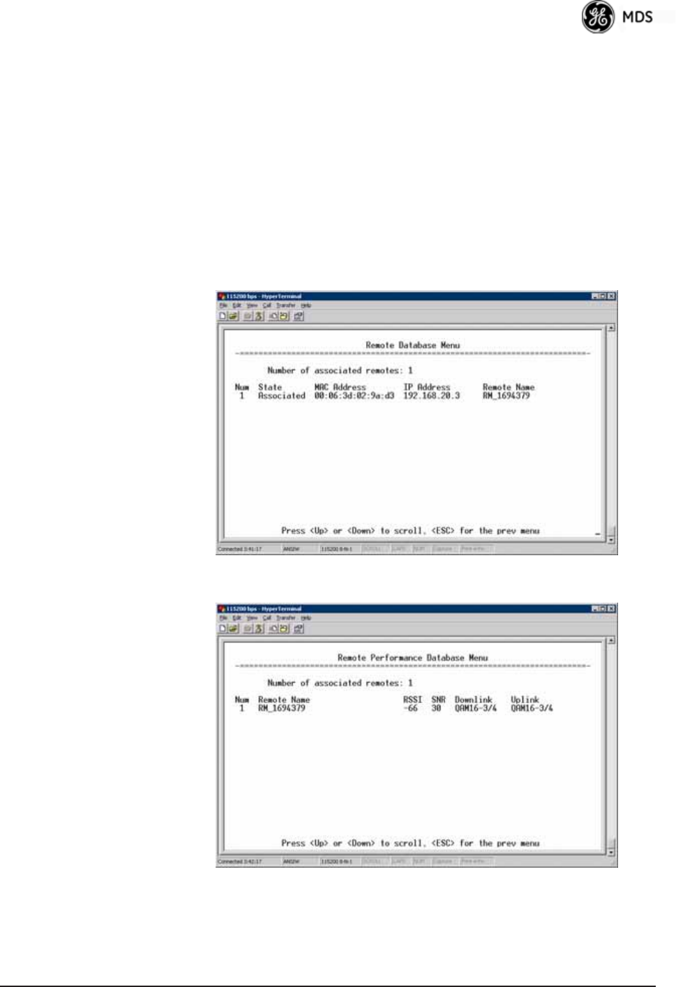
05-4446A01, Rev. E Mercury Reference Manual 119
•Connection Status (Remote Only)—Displays the current state of
the wireless network communication as follows: Scanning, Rang-
ing, Connecting, Authenticating, Associated, or Alarmed. A complete
explanation of these operating states is provided in Table 4-3 on
Page 152.
•Current AP Eth Address—Displays the Ethernet MAC address of
the current AP.
•Current AP IP Address—Shows the IP address of the current AP.
•Current AP Name—Displays the device name of the current AP.
•Time Connected—Shows the time at which the remote connected
to the AP. The Remote has been continually connected since
this time. Invisible place holder
Figure 3-92. Remote Database Menu
Invisible place holder
Figure 3-93. Remote Performance Database Menu
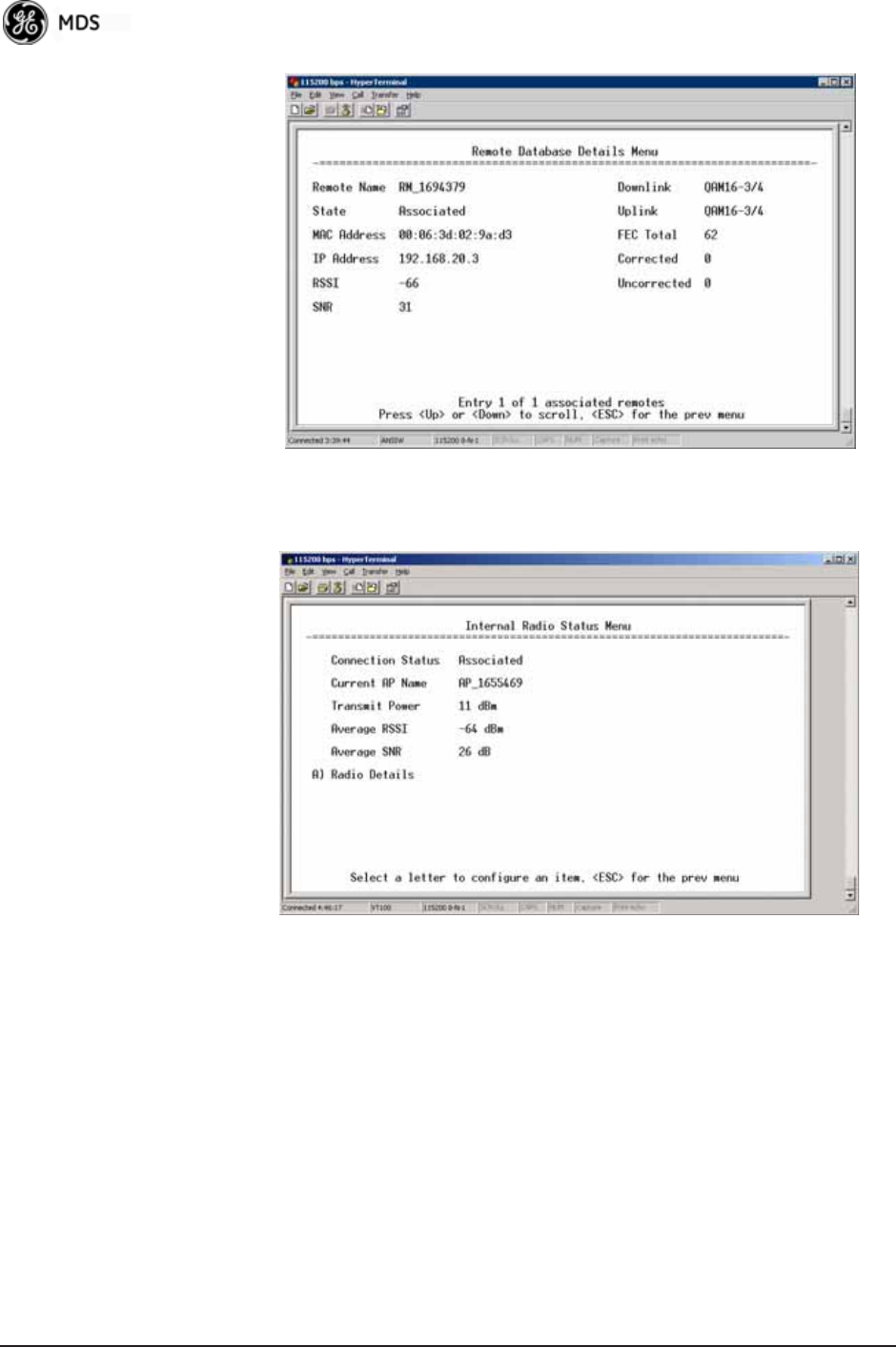
120 Mercury Reference Manual 05-4446A01, Rev. E
Invisible place holder
Figure 3-94. Remote Database Details Menu (AP)
Internal Radio Status Menu (Remote Only)
Invisible place holder
Figure 3-95. Internal Radio Status (Remote Only)
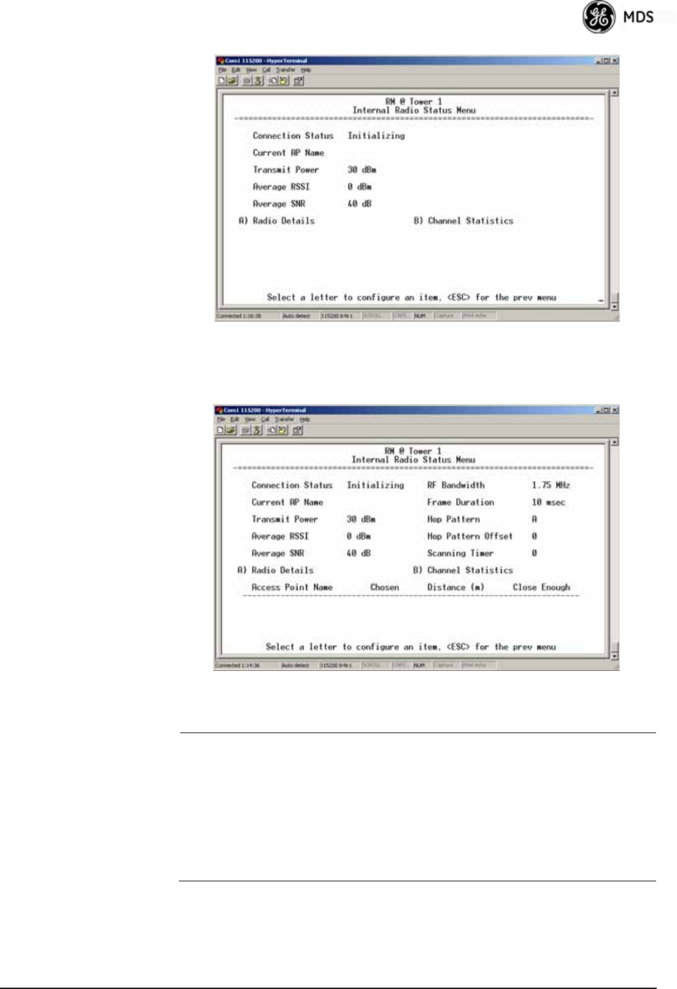
05-4446A01, Rev. E Mercury Reference Manual 121
Invisible place holder
Figure 3-96. Internal Status Menu
(Remote in Static Hopping mode)
Invisible place holder
Figure 3-97. Internal Radio Status Menu
(Remote in Hopping with Handoffs Mode)
NOTE: In the menu above, the items in the right hand column are
displayed on Remotes only, when they are in Hopping with
Handoffs mode. This allows viewing of the settings the
Remote is using to connect to each AP in the AP Locations
File. See Frequency Control Menu on Page 67 for explanations
of these items. Exception: The Scanning Timer parameter is
unique to the screen shown in Figure 3-97, and is explained
below.
•Connection Status—Indicates whether or not the Remote station
has associated with an AP.
[Associated, Scanning, Ranging, Connecting, Authorizing]
•Current AP Name—Shows the Device Name of the current AP.
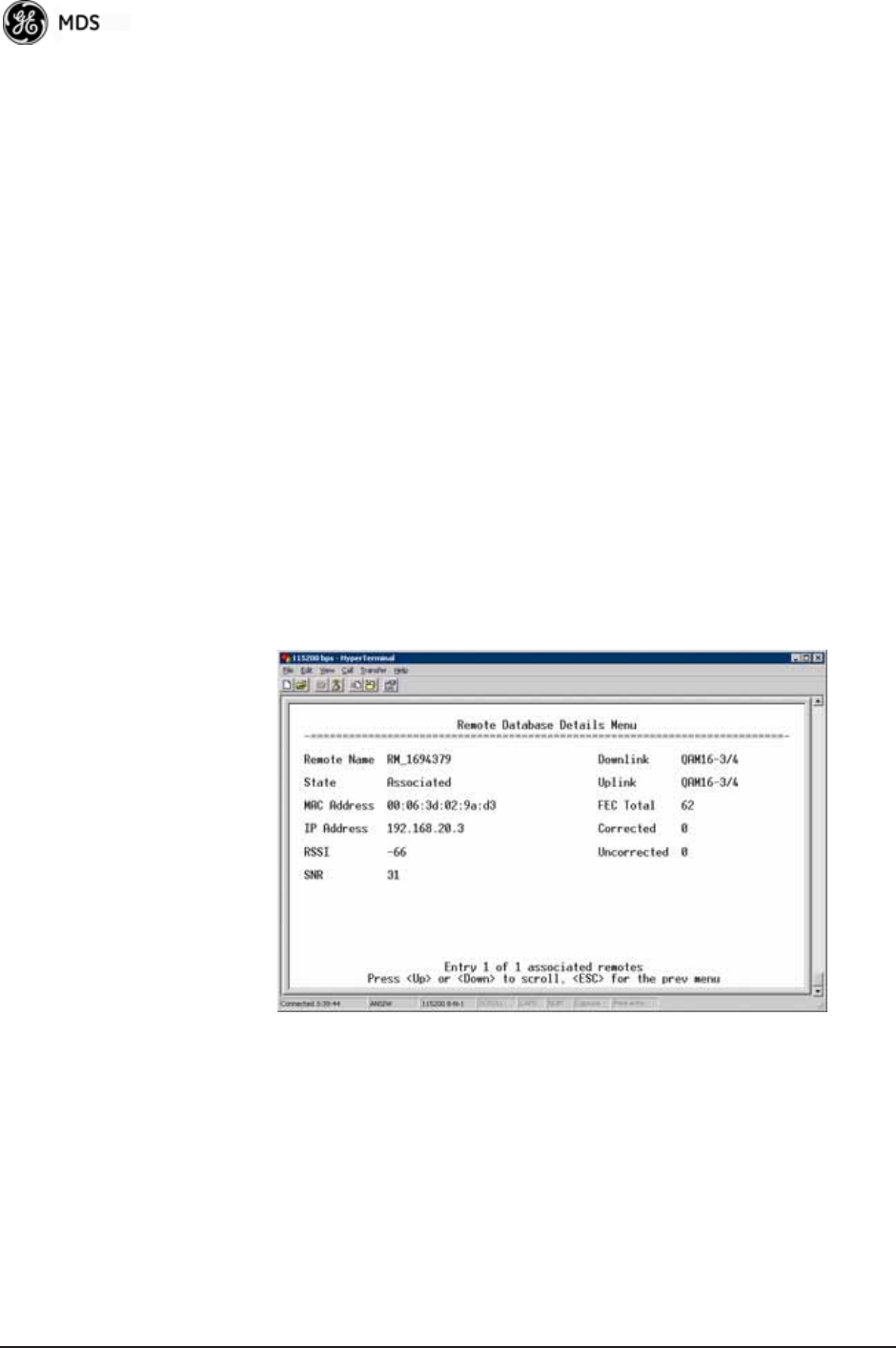
122 Mercury Reference Manual 05-4446A01, Rev. E
•Transmit Power—Shows the RF power output from the transmit-
ter. The AP changes the transmit power of the Remote to match
the desired receive power at the APs receiver. This provides
end-to-end power control.
•Average RSSI—Shows average received signal strength indica-
tion (RSSI) of incoming RF signals, displayed in dBm.
•Average SNR—Shows average signal-to-noise-ratio (SNR) of
received signals, displayed in dB. This is a measurement of the
quality of the incoming signal. It is possible for incoming sig-
nals to be strong, yet be affected by interference or other noise,
resulting in a low SNR. Use this parameter to help determine the
actual quality of signals.
•Scanning Timer—A timer that runs while the Remote radio tries
to connect to a particular AP. Once this timer reaches the Max
Scanning Time, the Remote tries to connect to the next AP in
the AP Locations File.
•Radio Details—This selection presents a screen (Figure 3-98)
showing key operating details of the transceiver.
•Channel Statistics—This selection presents a screen
(Figure 3-99) that shows signal quality on a channel-by-channel
basis. Readings are expressed in RSSI dBm and Signal-to-Noise
Ratio (SNR) dB, respectively.Invisible place holder
Figure 3-98. Radio Details Menu
•RSSI—Shows received signal strength indication (RSSI) in
dBm.
•SNR—Shows signal-to-noise ratio (SNR) in dB.
•TX Frequency Offset—Shows the RF carrier shift of the Remote’s
transmitter, measured in Hertz (Hz). The transmitted frequency
is continually reviewed and adjusted to agree with what the AP
expects to see. This optimization results in more efficient oper-
ation, corrects for doppler shift, and results in higher throughput
between AP and Remote stations.
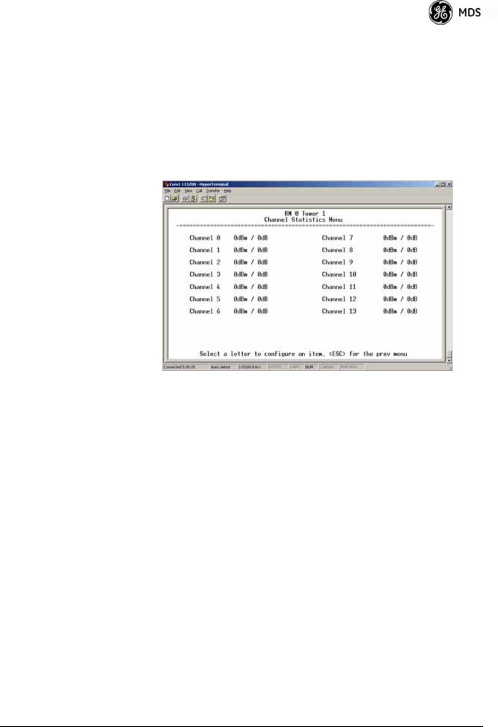
05-4446A01, Rev. E Mercury Reference Manual 123
•RX Frequency Offset—This is a measurement of how far in fre-
quency the Remote’s receiver has shifted (in Hz) to accommo-
date the incoming signal from the AP.
•Total FEC Count—This parameter shows the total number of For-
ward Error Correction (FEC) blocks handled by the radio.
•Corrected FEC Count—Displays the number of errored blocks
corrected with FEC by the radio.
•Uncorrected FEC Count—Shows the number of errored blocks
that can’t be corrected with FEC by the radio.
Invisible place holder
Figure 3-99. Channel Statistics Menu
3.12 MAINTENANCE/TOOLS MENU
In the course of operating your network, you may wish to upgrade trans-
ceiver firmware to take advantage of product improvements, work with
configuration scripts, conduct “ping” tests of your system, or reset oper-
ating parameters to factory default settings. All of these tasks are per-
formed using the Maintenance/Tools Menu (Figure 3-100). This section
explains how to take advantage of these services.
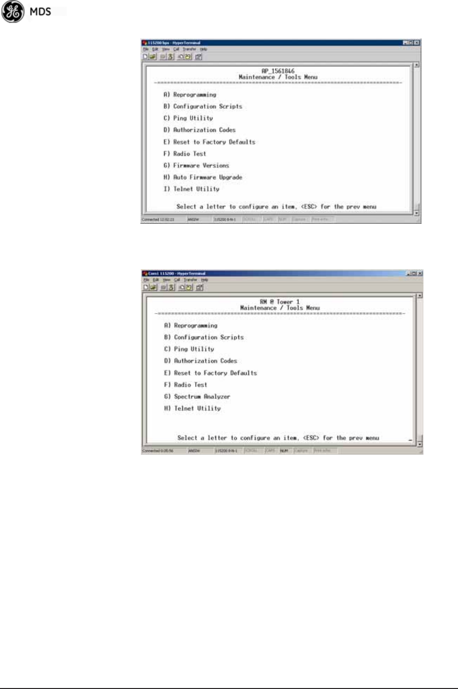
124 Mercury Reference Manual 05-4446A01, Rev. E
Invisible place holder
Figure 3-100. Maintenance/Tools Menu (AP)
Invisible place holder
Figure 3-101. Maintenance/Tools Menu (Remote)
(Some versions may show a Scheduled Reboot option, described below)
•Reprogramming—Managing and selecting the unit’s operating
system firmware resources. (See “Reprogramming Menu” on
Page 126)
•Configuration Scripts—Saving and importing data files contain-
ing unit operating parameters/settings. (See “Configuration
Scripts Menu” on Page 131)
•Ping Utility—Diagnostic tool to test network connectivity.
(See “Ping Utility Menu” on Page 135)
•Authorization Codes—Alter the unit’s overall capabilities by
enabling the built-in resources. (See “Authorization Codes” on
Page 136)
•Reset to Factory Defaults—Restores parameters to factory default
settings. (See “Reset to Factory Defaults” on Page 137)
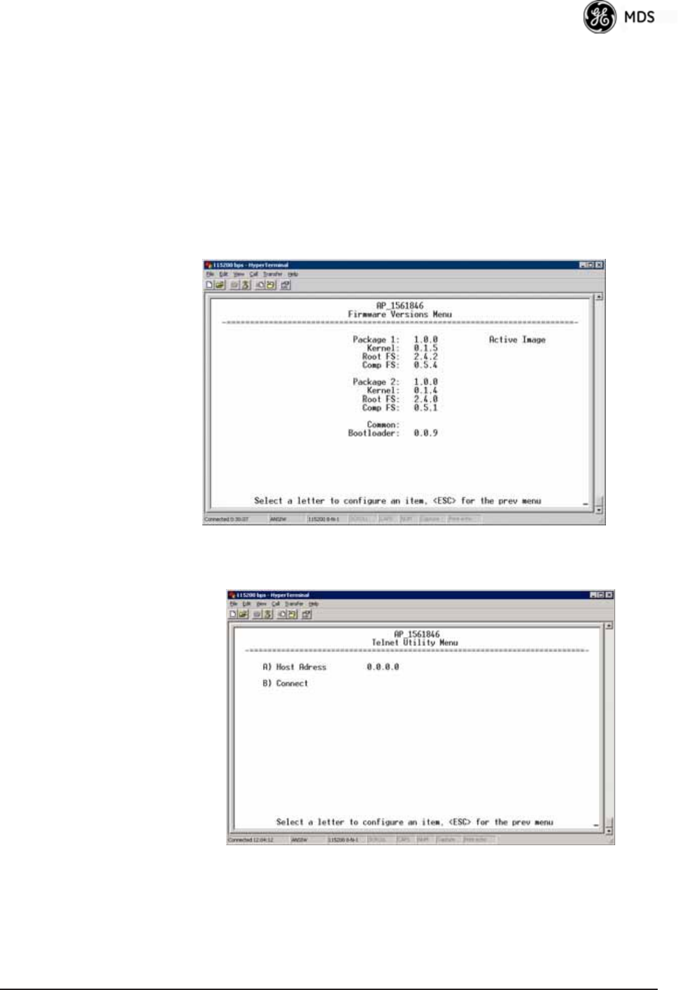
05-4446A01, Rev. E Mercury Reference Manual 125
•Radio Test—A diagnostic tool for testing RF operation.
(See “Radio Test Menu” on Page 138)
•Firmware Versions—Shows the firmware code versions stored in
the radio and indicates which one is the active image. (See
Figure 3-102 on Page 125.)
•Auto Firmware Upgrade—Brings up a submenu where you can
perform tasks related to loading new firmware. (See “ Auto
Firmware Upgrade Menu (AP Only)” on Page 138.)
•Telnet Utility—A submenu for opening Telnet connections to net-
work devices (Figure 3-103 on Page 125).
Invisible place holder
Figure 3-102. Firmware Versions Menu
Figure 3-103. Telnet Utility Menu
•Host Address—The IP address of the target device.
•Connect—Connect to the target device at the host address.
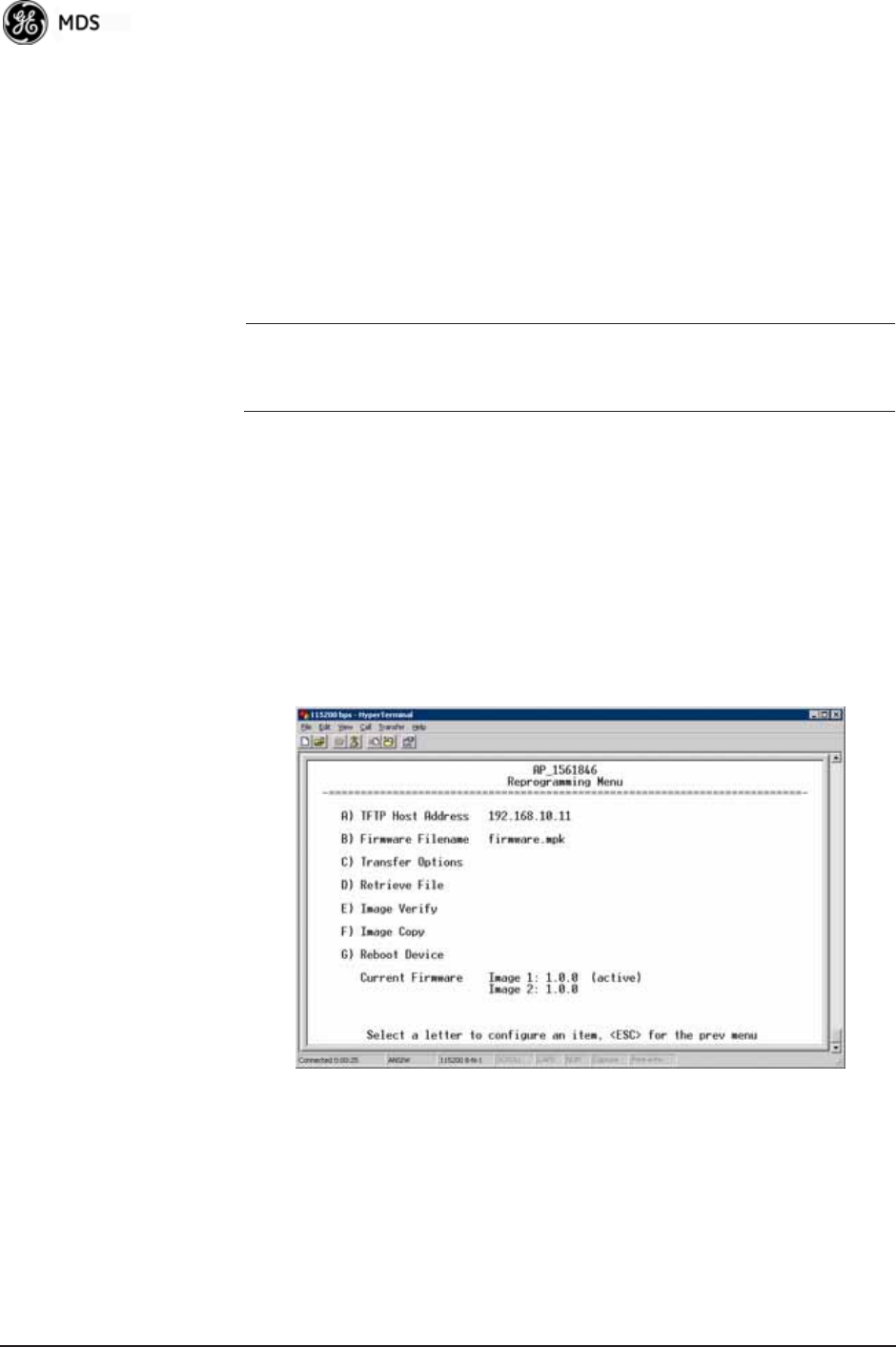
126 Mercury Reference Manual 05-4446A01, Rev. E
Reprogramming Menu
The factory sometimes offers upgrades to the transceiver firmware.
Loading new firmware into the unit will not alter any privileges pro-
vided by Authorization Keys and does not require you to take the trans-
ceiver off-line until you want to operate the unit with the newly installed
firmware image.
Firmware images are available free-of-charge at:
www.GEmds.com/Resources/TechnicalSupport/
NOTE: Always read the release notes for downloaded firmware. These
notes contain important information on compatibility and any
special steps needed for proper installation.
All units and versions have two resident images. Version 1.4.4 had
two.mpk files, one for the Access Point and one for the Remote. As of
version 2.1.0, there is only one mpk file which you can use with both
Access Points and Remotes.
The transceiver has two copies of the firmware (microprocessor code)
used for the operating system and applications. One copy is “active” and
the second is standing by, ready to be used once activated. You can load
new firmware into the inactive position and place it in service whenever
you desire.
Invisible place holder
Figure 3-104. Reprogramming Menu (AP)
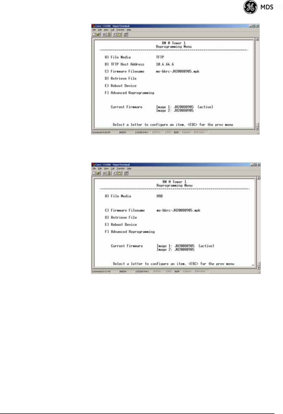
05-4446A01, Rev. E Mercury Reference Manual 127
Invisible place holder
Figure 3-105. Reprogramming Menu
(Option Set 1 Remote only)
Invisible place holder
Figure 3-106. Reprogramming Menu
(Option Set 1 Remote only)
•File Media—A selection of methods for transferring files to and
from the radio. On firmware version 3.0 radios, the options are
TFTP and USB.
•TFTP Host Address—IP address of the host computer from which
to get the file. [Any valid IP address] This same IP address is used
in other screens/functions (reprogramming, logging, etc.).
Changing it here also changes it for other screens/functions.
•Firmware Filename—Name of file to be received by the TFTP
server. [Any 40-character alphanumeric string] Verify that this cor-
responds to the TFTP directory location. May require sub-direc-
tory, for example: me-bkrc-2_1_0.mpk.
•Transfer Options—A menu for configuring the TFTP transfer.
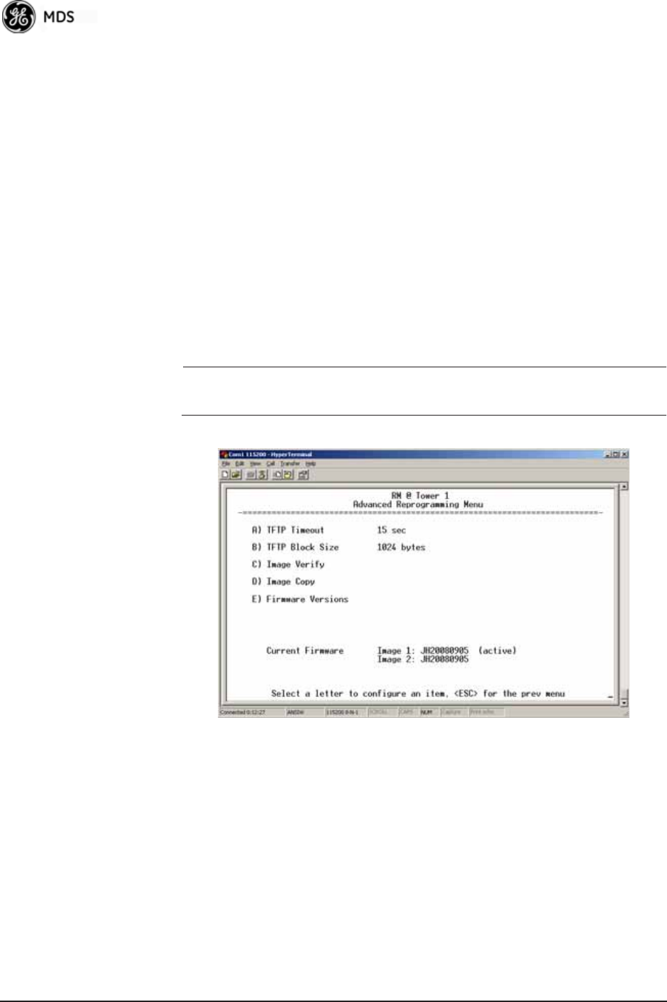
128 Mercury Reference Manual 05-4446A01, Rev. E
•Retrieve File—Initiates the file transfer from the TFTP server.
The new file is placed into inactive firmware image. [Y, N ]
•Image Verify—Initiate the verification of the integrity of firm-
ware file held in unit.
•Image Copy—Initiate the copying of the active firmware into the
inactive image.
•Reboot Device—Initiates rebooting of the transceiver. This will
interrupt data traffic through this unit, and the network if per-
formed on an Access Point. Intended to be used for switching
between firmware images 1 and 2.
•Advanced ReprogrammingAdvanced configuration options for
TFTP transfer of firmware files. See Figure 3-107 and related
text descriptions.
•Current Firmware—Displays the versions of firmware images
installed in the transceiver and shows whether Image 1 or Image
2 is currently active.
NOTE: See Upgrade Procedure on Page 130 for details on setting up
the TFTP server.
Invisible place holder
Figure 3-107. Advanced Reprogramming Menu
•TFTP Timeout—View/set the time (in seconds) where no activity
results in a TFTP timeout condition.
•TFTP Block Size—The data size of each TFTP block being trans-
ferred to the radio during firmware upgrade.
•Image Verify—Initiate the verification of the integrity of firm-
ware file held in unit.
•Image Copy—Initiate the copying of the active firmware into the
inactive image.
•Firmware Versions—Shows the available versions of firmware
code for operation of the radio.
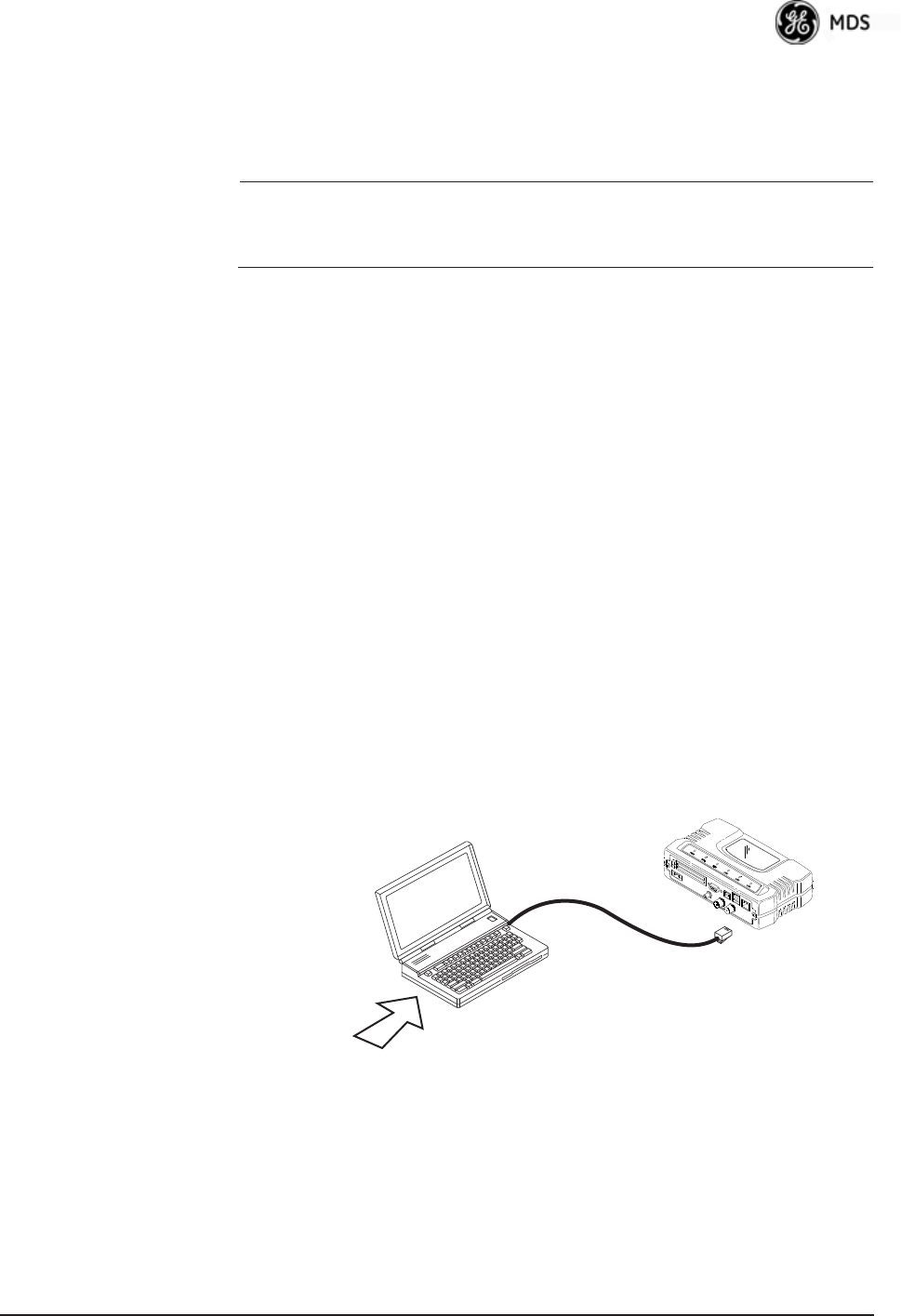
05-4446A01, Rev. E Mercury Reference Manual 129
3.12.1 Installing Firmware via TFTP
Firmware images are available free-of-charge at:
www.GEmds.com/Resources/TechnicalSupport/.
NOTE: You may not install AP firmware in Remote radios, or
vice-versa. This was only possible for early (pre-version 2.1.0)
firmware.
To install firmware by TFTP, you need:
• A PC with a TFTP server running
• The IP address of the PC running the TFTP server
• A valid firmware file
The IP address of the radio can be found under the Management
System’s Starting Information Screen. (See “Starting Information Screen”
on Page 42.)
A TFTP server is available on the GE MDS Web site at:
www.GEmds.com/Resources/TechnicalSupport/.
TIP: If you do not know your computer’s address on a Windows PC, you
can use the RUN function from the Start menu and enter winipcfg or
ipconfig to determine your local PC’s IP address.
There are several alternatives to connecting the transceiver for firmware
upgrades. Figure 3-108 and Figure 3-109 show two variations. It is
essential that all equipment be on the same subnet.
Invisible place holder
Figure 3-108. Firmware Upgrade SetupOption 1
(TFTP Server and Firmware File on Same CPU)
LAN
PORT
LOCAL WINDOWS PC
WITH CONFIG. FILES
IP ADDRESS: 172.0.0.A
IP ADDRESS: 172.0.0.B
TFTP
SERVER
& TELNET
TRANSCEIVER
C
R
O
S
S
-
O
V
E
R
C
A
B
L
E
INITIATE UPLOAD
FROM HERE
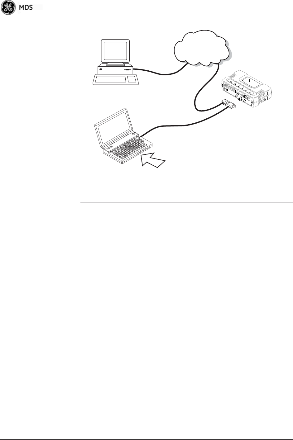
130 Mercury Reference Manual 05-4446A01, Rev. E
Invisible place holder
Figure 3-109. Firmware Upgrade SetupOption 2
(TFTP Server and Firmware File on Remote Server)
NOTE: The LAN and COM1 ports share a common data channel when
loading firmware over-the-air. Transferring the radio firmware
image file (≈ 6 MB) might take several minutes depending on
traffic between the TFTP server and the transceiver.
Regardless of your connection to the transceiver, loading firm-
ware/configuration files into the unit’s flash memory is much
slower than loading software onto a PC hard drive or RAM.
Upgrade Procedure To load a new firmware file (filename.mpk) into the transceiver, use the
following procedure:
1. Launch a TFTP server on a PC connected either directly or via a
LAN to the Ethernet port (LAN) of the radio. Point the server
towards the directory containing the firmware image file.
2. Connect to the Management System by whichever means is conve-
nient: browser or Telnet via the LAN, or Terminal emulator via the
COM1 port.
3. Go to the MS Reprogramming Menu.
(Main Menu>>Maintenance Menu>>Reprogramming Menu)
4. Fill in the information for the:
•TFTP Host Address—IP Address of server (host computer) run-
ning TFTP server.
•Firmware Filename—Name of file (filename.mpk) to be down-
loaded from the TFTP server holding the firmware file.
TRANSCEIVER
IP ADDRESS: 172.0.0.B
TFTP
SERVER ETHERNET
PORT
COM1
PORT
(DCE)
INITIATE UPLOAD
FROM HERE
REMOTE PC
W/FIRMWARE FILES
HUB/LAN/WAN/MAN
TCP/IP
LAN
PORT
COM1, 2, ETC.
(DTE)
IP ADDRESS: 172.0.0.A
LOCAL WINDOWS PC
IP ADDRESS: w.x.y.z
TERMINAL
PROGRAM
9
-
PI
NS
E
R
I
A
L
C
A
B
L
E
ST
RA
IG
H
T-T
H
R
U
C
A
BL
E

05-4446A01, Rev. E Mercury Reference Manual 131
5. Download the firmware file from the TFTP server into the trans-
ceiver.
(Main Menu>>Maintenance Menu>>Reprogramming Menu>>Retrieve File)
Status messages on the transfer are posted on the Management Sys-
tem screen.
NOTE: The new firmware image file that replaces the “Inactive
Image” file is automatically verified.
6. Reboot the transceiver.
Main Menu>>Maintenance Menu>>Reprogramming Menu>>Reboot Device
7. Test the transceiver for normal operation.
End of Procedure
Error Messages During File Transfers
It is possible to encounter errors during a file transfer. In most cases,
these can be corrected by performing the actions described in Table 3-9.
Configuration Scripts Menu
A configuration script file contains all of a radio’s setable parameters
that are accessible through the menu interface, with a few exceptions. A
configuration script file is in plain text format and can be easily edited
in any text program.
Configuration scripts can be helpful in several ways. Three common
uses for them are:
Table 3-9. Common Errors During TFTP Transfer
Error Message Likely Cause/Corrective Action
Invalid File Type Indicates that the file is not a valid firmware
file. Locate proper file and re-load.
File not found Invalid or non-existent filename on TFTP
server.
Invalid file path Invalid or non-existent file path to TFTP
server.
Timeout TFTP transfer time expired. Increase the
timeout value.
Flash Error Flash memory error. Contact factory for
assistance.
Bad CRC Cyclic Redundancy Check reporting a
corrupted file. Attempt to re-load, or use a
different file.
Version String Mismatch Invalid file detected. Attempt to re-load, or use
a different file.
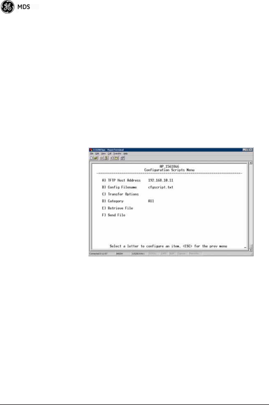
132 Mercury Reference Manual 05-4446A01, Rev. E
• To save “known-good” configuration files from your radios.
These can be used for later restoration if a configuration prob-
lem occurs, and it is unclear what parameter is causing the issue.
• To facilitate the rapid configuration of a large number of radios.
• To provide troubleshooting information when you contact the
factory for technical support. A technician can often spot poten-
tial problems by reviewing a configuration file.
How Configuration Files Work
When a configuration script file is downloaded to a radio (Retrieve File),
the radio executes the parameters as commands and takes the values
contained in it. When a configuration script file is uploaded from the
radio (Send), it contains the current values of the radio’s configuration
parameters. Figure 3-110 on Page 132 shows the Configuration Scripts
Menu.
Invisible place holder
Figure 3-110. Configuration Scripts Menu
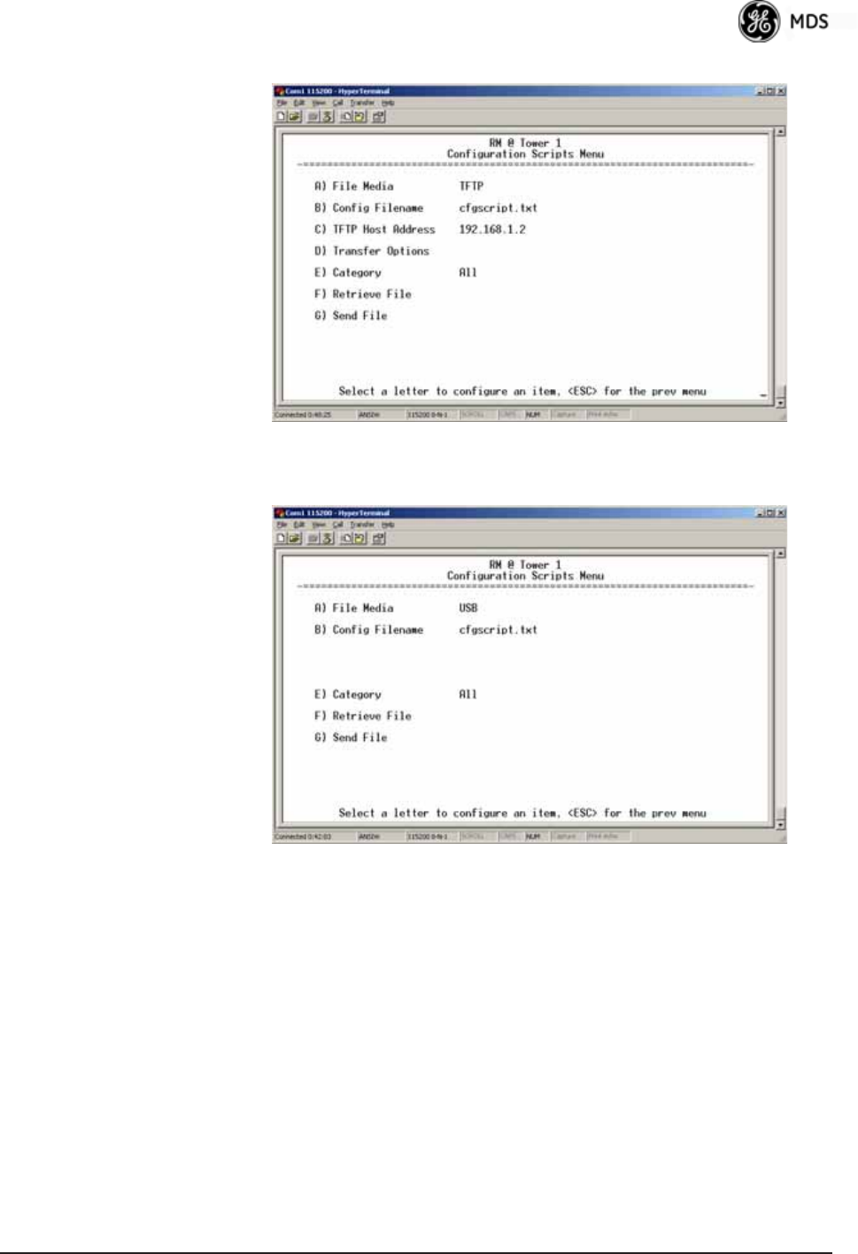
05-4446A01, Rev. E Mercury Reference Manual 133
Invisible place holder
Figure 3-111. Configuration Scripts Menu
(Option Set 1 Remote only)
Invisible place holder
Figure 3-112. Configuration Scripts Menu
(Option Set 1 Remote only)
•File Media—A selection of methods for transferring files to and
from the radio. On firmware version 3.0 radios, the options are
TFTP and USB.
•Config Filename—Name of file containing this unit’s configura-
tion profile that will be transferred to the TFTP server. The con-
figuration information is in plain-text ASCII format.
[Any 40-character alphanumeric string] May require a sub-direc-
tory, for example: config\mercury-config.txt. (See “Configuration
Scripts Menu” on Page 131 for more information.)

134 Mercury Reference Manual 05-4446A01, Rev. E
NOTE: The filename field is used to identify the desired incoming file
and as the name of the file exported to the TFTP server. Before
exporting a unit’s configuration, name it in a way that reflects
the radio’s services or other identification.
•TFTP Host Address—IP address of the computer on which the
TFTP server resides. [Any valid IP address]
•Transfer Options—A menu for configuring the TFTP transfer.
•Category—The category of parameters to send or receive.
•Retrieve File—Initiate the file transfer of the configuration file
from TFTP server into the transceiver.
•Send File—Initiate the file transfer from the transceiver’s current
configuration file to TFTP server.
NOTE: See “Upgrade Procedure” on Page 130 for details on setting
up the TFTP server.
Sample of Configuration Script File
A sample configuration script file is provided as part of every firmware
release. Firmware images and sample files are available free-of-charge
at: www.GEmds.com/Resources/TechnicalSupport/.
The name of the specific file includes the firmware revision number,
represented by the “x” characters in the following example:
mercury-config-x_x_x.txt.
Editing Configuration Files
Once a Remote unit’s operation is fine-tuned, use the Configuration
Scripts Menu on Page 131 to save a copy of the configuration onto a PC.
Once the file is saved on the PC, you can use it as a source to generate
modified copies adjusted to match other devices. Modify the configura-
tion files using a text editor or an automated process. (These applica-
tions are not provided by GE MDS).
We recommend that you review and update the following parameters for
each individual unit. Change other parameters as necessary. Save each
resulting file with a different name. We recommend using directories
and file names that reflect the location of the unit to facilitate later iden-
tification.
Table 3-10. Common User-Alterable Parameters
Field Comment Range
IP Address Unique for each individual radio. Any legal IP address
IP Gateway May change for different groups or
locations.
Any legal IP address
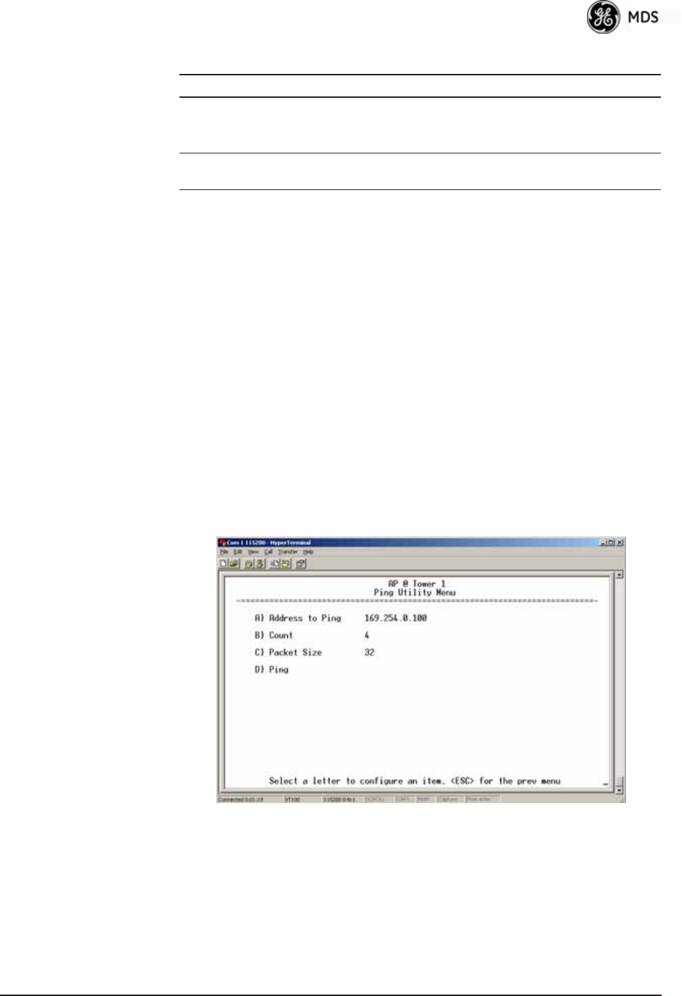
05-4446A01, Rev. E Mercury Reference Manual 135
Editing Rules • Only include parameters you want to change from the default
value.
• Change only the parameter values.
• Capitalization counts in some field parameters.
• Comment Fields:
a. Edit or delete anything on each line to the right of the
comment delineator, the semicolon (;).
b. Comments can be of any length, but must be on the same
line as the parameter, or on a new line that begins with a
semicolon character.
c. Comments after parameters in files exported from a trans-
ceiver do not need to be present in your customized files.
• Some fields are read-only. These are designated by “(RO)” in
the configuration sample file.
Ping Utility Menu Invisible place holder
Figure 3-113. Ping Utility Menu
•Address to Ping—Address to send a Ping. [Any valid IP address]
•Count—Number of Ping packets to be sent.
•Packet Size—Size of each Ping data packet (bytes).
Device Name Should reflect a specific device.
This information will appear in
Management System headings.
Any 20-character
alphanumeric string
Location Used only as reference for network
administration.
Any 40-character
alphanumeric string
Table 3-10. Common User-Alterable Parameters (Continued)
Field Comment Range
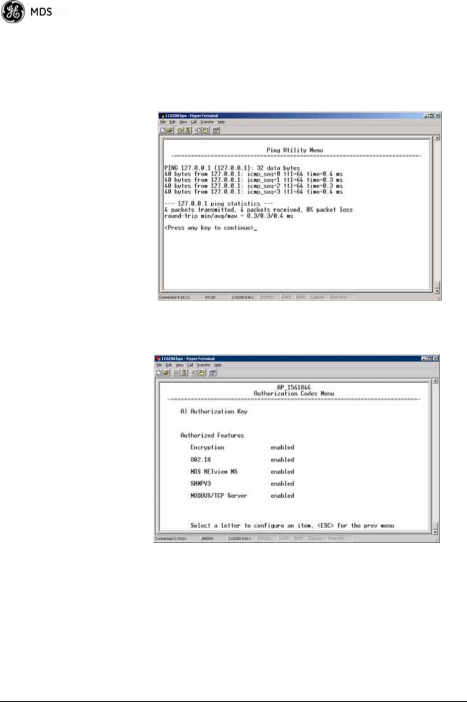
136 Mercury Reference Manual 05-4446A01, Rev. E
•Ping—Send Ping packets to address shown on screen.
This screen is replaced with a detailed report of Ping activity
(see example in Figure 3-114). Press any key after viewing the
results to return to this menu.
Invisible place holder
Figure 3-114. Ping Results Screen
Authorization Codes Invisible place holder
Figure 3-115. Authorization Codes Menu
•Authorization Key—For entering an Authorization Key into the
transceiver’s non-volatile memory.
•Authorized Features—List of the transceiver’s authorized fea-
tures. Each item shows enabled or disabled according to the set-
tings allowed by the Authorization Key entered into the radio.
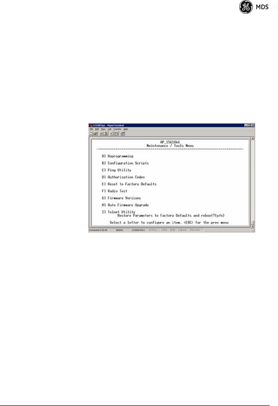
05-4446A01, Rev. E Mercury Reference Manual 137
Reset to Factory Defaults
Use the Reset to Factory Defaults selection on the Maintenance/Tools
Menu to return all configurable settings to those set at the factory prior
to shipping. Use this selection with caution, as you will lose any custom
settings you have established for your transceiver, and will need to
re-enter them using the menu system.
To prevent accidental use of the command, a “challenge” question is
presented at the bottom of the screen when this choice is selected (see
Figure 3-116 on Page 137). To proceed, enter y for yes or n for no, and
then press Enter. (You may also press the Escape key on your keyboard
to exit this command without making any changes.)
Invisible place holder
Figure 3-116. Reset to Factory Defaults Action
(Note challenge question at bottom of screen)
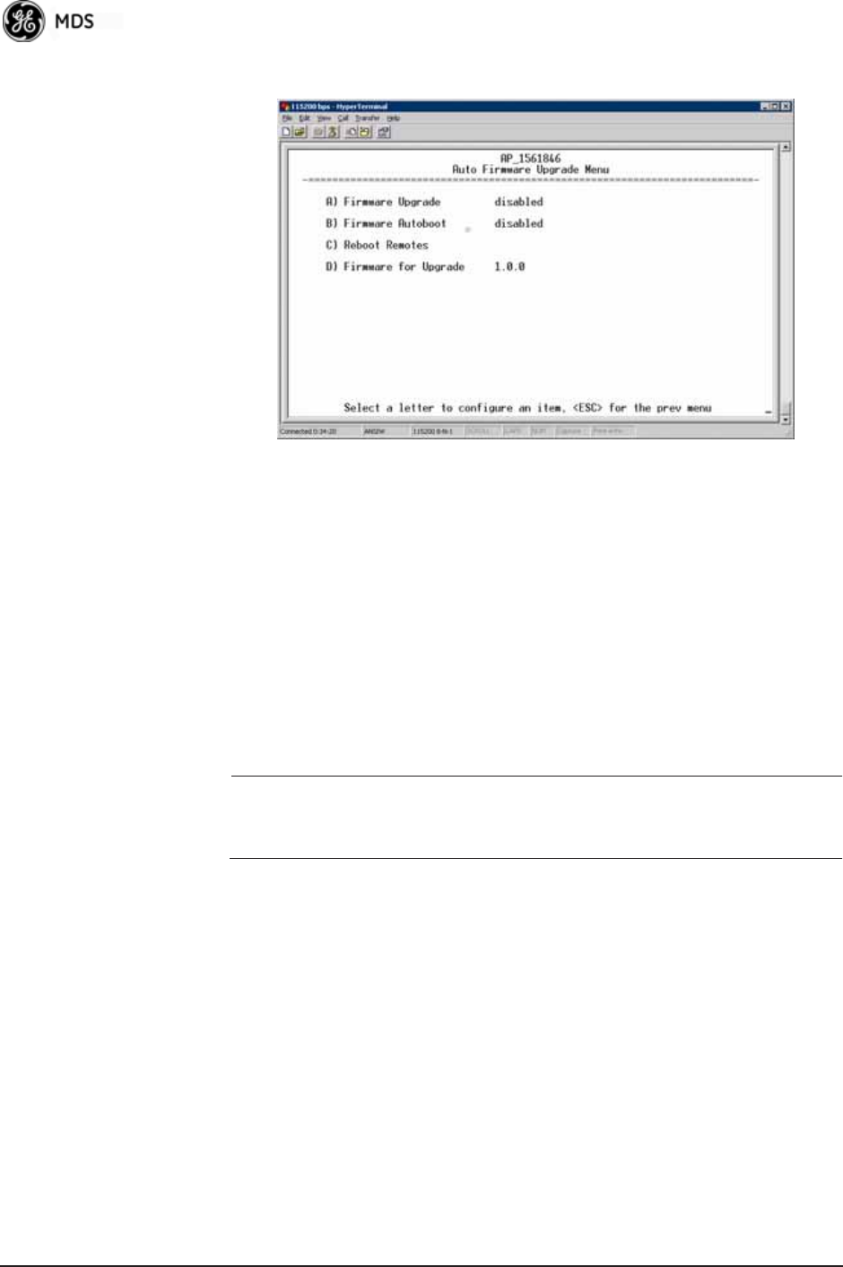
138 Mercury Reference Manual 05-4446A01, Rev. E
3.12.2 Auto Firmware Upgrade Menu (AP Only)
Invisible place holder
Figure 3-117.Auto Firmware Upgrade Menu
•Firmware Upgrade—Causes all of the Remotes associated to this
AP to read the AP’s specified (by Firmware for Upgrade) firmware
version (active or inactive), and download it via TFTP to the
inactive image if the Remote does not already have that firm-
ware version.
•Firmware Autoboot—Boot connected remotes to Firmware for
Upgrade (see below).
•Reboot Remotes—Determines how a Remote behaves once it has
downloaded new firmware from the AP as part of an
auto-upgrade. When enabled, the Remotes reboot to the new
firmware.
NOTE: To use the Auto Upgrade/Reboot feature, both the AP and
Remotes must already be running version 2.1.0 or newer firm-
ware.
•Firmware for Upgrade—Specifies the firmware version that the
Remotes should download, if they do not already have it.
Radio Test Menu
Using this menu, you can manually key the radio transmitter for perfor-
mance checks and set several parameters that will be used when the
Radio Mode is set to Test.
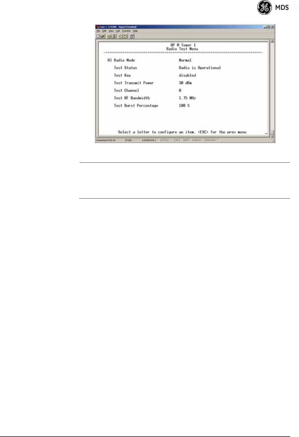
05-4446A01, Rev. E Mercury Reference Manual 139
Invisible place holder
Figure 3-118. Radio Test Menu
NOTE :Using Test Mode disrupts traffic through the radio. If the unit
is an Access Point, it will disrupt traffic through the entire
network. The Test Mode function is automatically limited to
10 minutes. Only use Test Mode for brief measurements.
•Radio Mode—Sets/displays the radio’s operating mode. To
change the setting, press A on the PC’s keyboard and press the
Spacebar to toggle between the two settings. Press the Enter key
to select the desired state. [Normal, Test; Normal]
•Test Status—This read-only parameter shows the current state of
the radio.
[Radio is Operational, Reconfiguring the Radio, Ready to KEY]
The following parameters are read-only unless A) Radio Mode is first
selected and set to Test. In Test Mode, these items become selectable,
and you can set their entries using the Spacebar or with a numeric entry,
followed by pressing the Enter key.
•Test Key—Sets/displays keying status of the radio’s transmitter.
Use the Spacebar to view selections. [disabled, enabled; disabled]
•Test Transmit Power—Sets/displays the transmitter’s power set-
ting. Make a numerical entry within the allowable range.
[3650 model: +23 dBm max]
[900 model: -30 to +29 dBm]
•Test Channel—Sets/displays the radio’s test channel number.
Make a numerical entry within the allowable range.
[0-13; 0]
•Test RF Bandwidth—Sets/displays the transmitter’s bandwidth for
testing. Use the Spacebar to view selections.
[1.75. 3.5 MHz; 1.75 MHz—additional selections for 3650 model]
•Test Burst Percentage—Sets/displays the percentage of Burst size
to use for testing. Make a numerical entry within the allowable
range. [0-100%; 100]
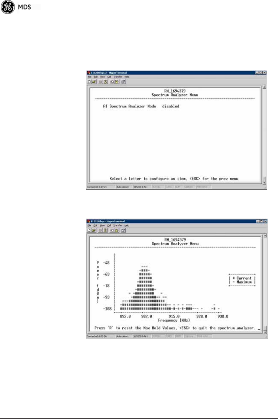
140 Mercury Reference Manual 05-4446A01, Rev. E
Spectrum Analyzer Menu (Remote Only)
Using this menu, you can enable or disable the remote’s spectrum ana-
lyzer mode (Figure 3-119 on Page 140). When enabled, the remote dis-
plays through the terminal a spectrum analyzer view of its transmit
power and frequency (Figure 3-120 on Page 140).
Figure 3-119. Spectrum Analyzer Menu
Figure 3-120. Spectrum Analyzer Display
3.13 PERFORMANCE OPTIMIZATION
After checking basic radio operation, you can optimize the network’s
performance. The effectiveness of these techniques varies with the
design of your system and the format of the data being sent.

05-4446A01, Rev. E Mercury Reference Manual 141
There are two major areas for possible improvement—the radio and the
data network. These sections provide a variety of items to check in both
categories, and in many cases, ways to improve performance.
NOTE: Antennas are one of the most important portions of the wire-
less system. A properly installed antenna with an unobstructed
path to associated stations is the optimal configuration, and
should be among the first items checked when searching for
performance gains.
Stronger signals allow the use of wider bandwidths and higher
data speeds with fewer retries of data transmissions. Time
spent optimizing the antenna systems on both AP and Remote
stations will often have a huge benefit to system performance.
Refer to INSTALLATION PLANNING on Page 163 for addi-
tional recommendations on antenna systems.
Table 3-11 on Page 142 provides suggested settings for typical installa-
tion scenarios. These settings provide a starting point for configuration
of AP and Remote units. Changes might be required to achieve the
desired results in a particular situation.

142 Mercury Reference Manual 05-4446A01, Rev. E
Table 3-11. Recommended Settings for Common Scenarios
For Fixed Locations, where best combination of range and throughput is desired.
AP Remote Units Notes
Radio Configuration
Network
Name
User
discretion
User
discretion
AP and Remote must match.
Transmit Power
(AP)/
Max Transmit Power (RM)
30
(3650 model: 23)
30
(3650 model: 23)
dBm In most cases, power can be set to this level
and left alone. Setting it lower helps control
cell overlap.
Receive Power -70 N/A dBm Sets AP receiver for medium gain. Typical
range: -60, -80 dBm.
Frequency Control
Frequency Mode Static Hopping Static Hopping
Frame Duration 20 20 ms Changing to 10 ms lowers latency. 5 and 8
ms selections not functional for this release.
Hop Pattern A, B, C, D A, B, C, D AP and RM must match.
Hop Pattern
Offset
0-13 or 0-6 0-13 or 0-6 AP and RM must match.
Channel
Selection
User
discretion
User
discretion
Disable channels with interference. AP and
RM must match.
TDD Sync Mode GPS Required N/A GPS Antennas must be connected to both
AP and RM.
Advanced Configuration
Adaptive
Modulation
Enabled Enabled
Protection
Margin
33dB
Hysteresis
Margin
33dB
Data
Compression
Enabled Enabled Gives best throughput numbers, but may
hide true performance if only tested with
PING or Text File FTP.
Max
Modulation
QAM/16-3-4 QAM16-3/4 Best combination of range and throughput.
Cyclic Prefix 1/16 N/A Best throughput setting.
Channel
Type
Static N/A Less periodic ranging when channel type is
Static.
ARQ Enabled N/A
ARQ Block Size 256 N/A bytes
ARQ Block
Lifetime
655 N/A ms
These 3 settings make the max. no. of ARQ
retries =9.
(655 ms)/(35 ms + 35 ms = 9.35=>9
ARQ TX
Delay
35 N/A ms
ARQ RX Delay 35 N/A ms
Adaptive Split Enabled N/A Maximizes one-way burst throughput.
Downlink% 50 N/A %If Adaptive Split is disabled, can set
downlink% to 15%–75%.

05-4446A01, Rev. E Mercury Reference Manual 143
3.13.1Proper Operation and What to Look For
Table 3-12 and Table 3-13 on Page 144 show target performance values
for AP and Remote transceivers. View these values using the built-in
menu system by navigating the path shown under each table title.
For Optimal Sensitivity
(Trades off throughput for best possible sensitivity. AP more susceptible to interference)
AP Remote Units Notes
Radio
Configuration
Receive
Power
-80 N/A dBm Sets AP receiver for highest gain.
When Heavy Interference Exists at AP
(Trades off range for robustness in the face of interference)
AP Remote Units Notes
Radio
Configuration
Receive
Power
-60 N/A dBm Sets AP receiver for low gain,
which forces Remote transmit
power to be high.
For Mobile Systems
(Where hand-offs between APs are required)
AP Remote Units Notes
Radio
Configuration
Frequency
Control
Frequency
Mode
Static
Hopping
Hopping
w/Hand-offs
Advanced
Configuration
Protection
Margin
66dBMore channel variation in
mobile, so use more robust
modulation with greater
SNRs.
Channel Type Dynamic N/A Less periodic ranging when
Channel Type = Static.
Network
Configuration
AP Location
Info Config
Retrieve Text
File
N/A AP
Locations file
AP locations file with
coordinates and key
attributes of APs to which
Remote can associate.
Table 3-12. Mercury Remote Transceiver
(Performance Information>>Internal Radio Status Menu)
Name Target Value Notes
Connection Status Associated Remote must be associated
for network operation.
Transmit Power Varies Adjusts automatically as
requested by AP.
RSSI
(Received Signal
Strength Indication)
Varies The less negative an RSSI
reading, the stronger the
signal (i.e., -75 dBm is
stronger than -85 dBm).

144 Mercury Reference Manual 05-4446A01, Rev. E
Additional Considerations for Mobile Operation
Consider the following key points for all mobile installations:
SNR
(Signal-to-Noise Ratio)
Strong signal (bench
setting): 25-28 dB
Operational: 3-30 dB
Typ. System: 10-20 dB
A low SNR may be caused by
noise or interfering signals.
TX Freq. Offset 0-22,875 Hz Adjusts to accommodate what
is expected by the AP.
RX Freq. Offset 0-22,875 Hz Adjusts to accommodate what
is expected by the AP.
Total FEC Count Varies
Corrected FEC Count Varies
Uncorrected FEC
Count
Varies
Current AP Name Device name of
associated AP
Typically set to reflect the
application or system the radio
is used in.
Table 3-12. Mercury Remote Transceiver (Continued)
(Performance Information>>Internal Radio Status Menu)
Name Target Value Notes
Table 3-13. Mercury Access Point
(Performance Information>>Wireless Network Status>>
Remote Performance Database)
Name Target Value Notes
MAC ADDR MAC Address of
associated Remote
Must match Remote’s MAC
address exactly
RSSI
(Received Signal
Strength Indication)
Varies The less negative an RSSI
reading, the stronger the
signal (i.e., -75 dBm is
stronger than -85 dBm).
SNR
Signal-to-Noise Ratio
Strong signal (bench):
25-28 dB
Operational: 3-30 dB
Typ. System:10-20 dB
A low SNR may be caused by
noise or interfering signals.
Downlink Varies QPSK/FEC-3/4 Preferred
Uplink Varies QPSK/FEC-3/4 Preferred
FEC Total Varies
Corrected FEC Count Varies
Uncorrected FEC
Count
Varies

05-4446A01, Rev. E Mercury Reference Manual 145
NOTE: 3650 MHz is for APs and Fixed Remote stations only.
• Use connectionware—The use of connectionware in the mobile lap-
tops is highly recommended for better operation of a mobile data
system. GE MDS provides connectionware from one of the vendors
in this market. Contact your factory representative for details.
• Plan your network coverage—Deploy Access Points so that they
provide overlapping coverage with each other. Access Points must
use the same Network Name to enable roaming service.
• Set the RSSI Threshold to -70 dBm—This level is typically used for
mobile systems with good performance. Make sure there is overlap-
ping coverage of more than one AP to provide continuous coverage.
• At every AP Radio, review the following settings when providing
service to mobile remotes:
•TDD Sync—Set to GPS Required.
•Pattern Offset—Each AP should be different. Cell planning is
required if there are overlaps.
•Hop Pattern—Set the same on all APs.
•Compression [disabled]—Disable radio compression. Data com-
pression is best performed by the connectionware running on
the mobile laptop PC. Gains in efficiency are made because
connectionware compresses data at a higher stack level, and it
aggregates multiple data frames and streams into a single
packet. Compression at the radio level, although highly effi-
cient, works only at the individual packet level.

146 Mercury Reference Manual 05-4446A01, Rev. E

05-4446A01, Rev. E Mercury Reference Manual 147
4 TROUBLESHOOTING &
RADIO MEASUREMENTS
4 Chapter Counter Reset Paragraph
Contents
4.1 TROUBLESHOOTING.............................................................149
4.1.1 Interpreting the Front Panel LEDs ...........................................149
4.1.2 Troubleshooting With the Embedded Management System .... 150
4.1.3 Using Logged Operation Events .............................................. 153
4.1.4 Alarm Conditions ......................................................................154
4.1.5 Correcting Alarm Conditions .................................................... 155
4.1.6 Logged Events ......................................................................... 155
4.2 RADIO (RF) MEASUREMENTS..............................................157
4.2.1 Antenna System SWR and Transmitter Power Output ............157
4.2.2 Antenna AimingFor Directional Antennas ............................. 158

148 Mercury Reference Manual 05-4446A01, Rev. E

05-4446A01, Rev. E Mercury Reference Manual 149
4.1 TROUBLESHOOTING
Successful troubleshooting of a wireless system is not difficult, but
requires a logical approach. It is best to begin troubleshooting at the
Access Point unit, as the rest of the system depends on the Access Point
for synchronization data. If the Access Point has problems, the operation
of the entire wireless network is affected.
When you find communication problems, it is good practice to begin by
checking the simple causes. Applying basic troubleshooting techniques
in a logical progression identifies many problems.
Multiple
Communication
Layers
It is important to remember that the operation of the network is built on
a radio communications link. On top of that are two data levels— wire-
less MAC, and the data layer. It is essential that the wireless aspect of
the Access Point and the Remotes units to be associated operates prop-
erly before data-layer traffic will function.
Unit Configuration There are numerous user-configurable parameters in the Management
System. Do not overlook the possibility that human error is the cause of
the problem. With so many parameters to view and change, a parameter
might be incorrectly set, and then that change is forgotten.
To help avoid these problems, GE MDS recommends creating an
archive of the transceiver’s profile in a Configuration File when your
installation is complete. You can reload this file into the transceiver to
restore the unit to the factory defaults or your unique profile. For details
on creating and archiving Configuration Files, see “Configuration
Scripts Menu” on Page 131.
Factory Assistance If problems cannot be resolved using the guidance provided here,
review the GE MDS web site’s technical support area for recent soft-
ware/firmware updates, general troubleshooting help, and service infor-
mation. Additional help is available through our Technical Support
Department. (See “TECHNICAL ASSISTANCE” on the inside of the
rear cover.)
4.1.1 Interpreting the Front Panel LEDs
An important set of troubleshooting tools are the LED status indicators
on the front panel of the radio case. You should check them first when-
ever a problem is suspected. Table 2-2 on Page 30 describes the func-
tion of each status LED. Table 4-1 on Page 150 provides suggestions for

150 Mercury Reference Manual 05-4446A01, Rev. E
resolving common system difficulties using the LEDs, and Table 4-2 on
Page 151 provides other simple techniques.
4.1.2 Troubleshooting With the Embedded
Management System
If you have reviewed and tried the items listed in Table 4-1 and still have
not resolved the problem, there are additional tools and techniques you
can use. The embedded Management System is a good source of infor-
mation that you can use remotely to provide preliminary diagnostic
information, or may even provide a path to correcting the problem.
Refer to Table 4-2 on Page 151 for more information on using the Man-
agement System as a troubleshooting tool.
Table 4-1. Troubleshooting Using LEDs—Symptom-Based
Symptom Problem/Recommended System Checks
PWR LED does not
turn on
a. Voltage too low—Check for the proper supply voltage at
the power connector. (10–30 Vdc)
b. Indefinite Problem—Cycle the power and wait
(≈ 30 seconds) for the unit to reboot. Then, recheck for
normal operation.
LINK LED does not
turn on
a. Network Name of Remote not identical to desired Access
Point—Verify that the system has a unique Network Name.
b. Not yet associated with an Access Point with the same
Network Name.
Check the “Status” of the unit’s process of associating with
the Access Point. Use the Management System.
c. Poor Antenna System—Check the antenna, feedline and
connectors. Reflected power should be less than 10% of
the forward power reading (SWR 2:1 or lower).
PWR LED is
blinking
a. Blinking indicates that an alarm condition exists.
b. View Current Alarms and Event Log and correct the
problem if possible.
(See “Using Logged Operation Events” on Page 153)
c. Blinking continues until the source of the alarm is
corrected, for example, a valid IP address is entered, etc.
LAN LED does not
turn on
a. Verify the Ethernet cable is connect at both ends.
b. Verify that the appropriate type of Ethernet cable is used:
straight-through or crossover.
LAN LED lights, but
turns off after some
time
Verify traffic in LAN. Typically, the radio should not be placed
in high traffic enterprise LANs, as it will not pass this level of
traffic. If needed, use routers to filter traffic.
GPS LED not lit No satellite fix has been obtained. A fix is required for all
operation except single-frequency channel (non-hopping)
configurations. The lack of a fix may be caused by an
obstructed “view” of the satellites, or a GPS antenna problem.
The GPS LED blinks slowly on the AP while it synchronizes its
internal clock to the GPS signal. When in this condition, the AP
does not transmit.

05-4446A01, Rev. E Mercury Reference Manual 151
The following is a summary of how you can use several screens in the
Management System as diagnostic tools. For information on how to
Table 4-2. Basic Troubleshooting Using the Management System
Symptom Problem/Recommended System Checks
Cannot access the
MS through COM1
a. Connect to unit via Telnet or Web browser.
b. Disable the serial mode for COM1
(Serial Gateway Configuration>>Com1 Serial Data
Port>>Status>>Disabled).
Or, if you know the unit’s data configuration:
a. Connect to COM 1 via a terminal set to VT100 and the
port’s data baud rate.
b. Type +++.
c. Change the terminal’s baud rate to match the transceiver’s
Console Baud Rate.
d. Type +++.
Display on
terminal/Telnet
screen garbled
Verify the terminal/terminal emulator or Telnet application is
set to VT100.
Password forgotten a. Connect to the transceiver using a terminal through the
COM1 Port.
b. Obtain a password-resetting Authorization Key from your
factory representative.
c. At the login prompt, try the user name authcode, and enter
the Authorization Key for the password.
Remote only gets
to Connecting
a. Check Network Name, encryption, and Device Auth Mode
settings.
b. Verify that the correct MAC address is listed in the
Approved Remotes List of the Security Configuration
Menu.
Remote only gets
to Authenticating
Check encryption settings and security mode settings.
Cannot pass IP
data to WAN
a. Verify your IP settings.
b. Use the PING command to test communication with the
transceivers in the local radio system.
c. If successful with local PING, attempt to PING an IP unit
attached to a transceiver.
d. If successful with the LAN PINGs, try connecting to a
known good unit in the WAN.
Wireless Retries
too high
Possible Radio Frequency Interference:
a. If omnidirectional antennas are used, consider changing to
directional antennas. This usually limits interference to and
from other stations.
b. Try disabling channels where persistent interference is
known or suspected.
c. The installation of a filter in the antenna feedline may be
necessary. Consult the factory for further assistance.
d. Try using an antenna with a downward tilt.

152 Mercury Reference Manual 05-4446A01, Rev. E
connect to the Management System, see “STEP 3: CONNECT PC TO
THE TRANSCEIVER” on Page 25.
Starting Information Screen
(See Starting Information Screen on Page 42)
The Management System’s home page provides some valuable bits of
data. One of the most important is the Device Status field. This item tells
you if the unit is operational.
If the Device Status field says Associated, then look in the network areas
beginning with network data statistics. If it displays some other mes-
sage, such as Scanning, Connecting, or Alarmed, you must determine why
it is in this state.
The Scanning state indicates a Remote unit is looking for an Access
Point beacon signal to lock onto. It should move to the Connecting state
and finally to the Associated state within less than a minute. If this
Remote unit is not providing reliable service, look at the Event Logs for
signs of lost association with the Access Point, or low signal alarms.
Table 4-3 provides a description of the Device Status messages.
If the Remote is in an Alarmed state, the unit might still be operational
and associated. Look for the association state in the Wireless Network
Status screen to determine if the unit is associated. If it is, look at the
Error Log for possible clues.
If the unit is in an Alarmed state and is not associated with an Access
Point, then there might be a problem with the wireless network layer.
Call a radio technician to deal with wireless issues. Refer the technician
to the RADIO (RF) MEASUREMENTS on Page 157 for information on
antenna system checks.
Table 4-3. Device Status1
1. Device Status is available in the Startup Information Screen or the Wireless Status
Screen at Remotes.
Scanning The unit is looking for an Access Point beacon signal.
Ranging Remote has detected AP and is synchronizing to it.
Connecting The Remote has established a radio (RF) connection
with the Access Point and is negotiating the network
layer connectivity.
Authenticating2
2. If Device Authentication is enabled.
The Remote is authenticating itself to the network to
obtain cyber-security clearance in order to pass data.
Associated This unit has successfully synchronized and is
“associated” with an Access Point. This is the normal
operating state.
Alarmed The unit has detected one or more alarms that have not
been cleared.

05-4446A01, Rev. E Mercury Reference Manual 153
Packet Statistics Menu
(See Packet Statistics Menu on Page 114)
This screen provides detailed information on data exchanges between
the unit being viewed and the network through the wireless and the
Ethernet (data) layers. These include:
The most significant fields are the Packets Dropped, Retries, Retry
Errors, Receive Errors and Lost Carrier Detected. If the data values are
more than 10% of their sent and received counterparts, or the Lost Car-
rier Detected value is greater than a few dozen, there might be trouble
with radio-frequency interference or a radio link of marginal strength.
If errors are excessive, check the aiming of the antenna system, and
check for a satisfactory SWR. Refer to RADIO (RF) MEASUREMENTS
on Page 157 for information on antenna system checks.
Diagnostic Tools
(See MAINTENANCE/TOOLS MENU on Page 123)
The radio’s Maintenance menu contains two tools that are especially
useful to network technicians—the Radio Test Menu and the Ping
Utility. Use the Radio Test selection for testing RF operation. Use the
Ping Utility to verify communications access to pieces of equipment
connected to the radio network. This includes transceivers and user-sup-
plied Ethernet devices.
4.1.3 Using Logged Operation Events
(See PERFORMANCE INFORMATION MENU on Page 110)
The transceiver’s microprocessor monitors many operational parame-
ters and logs them as various classes of events. If the event is one that
affects performance, it is an alarm. There are also normal or routine
events such as those marking the rebooting of the system, implementa-
tion of parameter changes, and external access to the Management
System. Informational events are stored in temporary (RAM) memory
that is lost in the absence of primary power, and Alarms are stored in
Wireless Packet Statistics
• Packets received • Packets dropped
• Packets sent • Receive errors
• Bytes received • Retries
• Bytes sent • Retry errors
Ethernet Packet Statistics
• Packets received • Packets dropped
• Packets sent • Receive errors
• Bytes received • Retries
• Bytes sent • Retry errors
• Lost carrier detected

154 Mercury Reference Manual 05-4446A01, Rev. E
permanent memory (Flash memory) until cleared by user request.
Table 4-4 summarizes these classifications.
These events are stored in the transceiver’s Event Log and can be a valu-
able aid in troubleshooting unit problems or detecting attempts at
breaching network security.
4.1.4 Alarm Conditions
Most events, classified as “critical” will cause the PWR LED to blink,
and will inhibit normal operation of the transceiver. The LED blinks
until the corrective action is completed. (See also Event Log Menu on
Page 113.)
Table 4-4. Event Classifications
Level Description/Impact Storage
Alarms Transceiver has detected one or
more alarm conditions
Flash
Memory
Informational Normal operating activities Flash
Memory
Temporary
Informational
Transient conditions or events RAM
Minor Does not affect unit operation RAM
Major Degraded unit performance but
still capable of operation
RAM
Critical Prevents the unit from operating RAM
Table 4-5. Alarm Conditions (Alphabetical Order)
Alarm Condition Reported Event Log Entry SNMP Trap
EVENT_BRIDGE Network Interface /Error networkInterface(17)
EVENT_FREQ_CAL Frequency Not
Calibrated
frequencyCal(7)
EVENT_INIT_ERR Initialization Error initializationError(18)
EVENT_IPADDR*IP Address Invalid ipAddressNotSet(4)
EVENT_IPMASK*IP Mask Invalid ipNetmaskNotSet(5)
EVENT_LAN_PORT lanPortStatus(78)
EVENT_MAC MAC communication
Failed
macCommunication(1)
EVENT_MACADDR MAC Address Invalid noMacAddress(6)
EVENT_NETNAME*Netname Invalid invalidNetname(12)
EVENT_POWER_CAL Power Calibrated/Not
Calibrated
powerCal(8)
EVENT_REMOTE Remote Added/
Removed (AP Only)
eventRemote(66)
EVENT_RSSI*RSSI Exceeds
threshold
rssi(11)

05-4446A01, Rev. E Mercury Reference Manual 155
* User can correct condition, clearing the alarm.
4.1.5 Correcting Alarm Conditions
(See Event Log Menu on Page 113)
Table 4-6 provides likely causes of events that inhibit the unit from
operating, and possible corrective actions. The Event Description
column appears on the Event Log screen.
4.1.6 Logged Events
The following events allow the transceiver to continue operation and do
not make the PWR LED blink. Each is reported through an SNMP trap.
EVENT_RSSI_CAL RSSI Not Calibrated rssiCal(9)
EVENT_SYSTEM_ERROR* System Error Cleared;
Please Reboot
systemError(16)
EVENT_TFTP_CONN TFTP connectivity
achieved
tftpConnection(73)
EVENT_TFTP_ERR Attempted TFTP
connection failed
tftpConnFailed(79)
Table 4-5. Alarm Conditions (Alphabetical Order) (Continued)
Alarm Condition Reported Event Log Entry SNMP Trap
Table 4-6. Correcting Alarm Conditions—Alphabetical Order
Event Log Entry Generating Condition Clearing Condition
or Action
Bridge Down The Bridge fails to be
initialized.
Contact factory Technical
Services for assistance.
General System
Error
Internal checks suggest unit
is not functioning properly.
Reboot the transceiver.
Initialization Error Unit fails to complete boot
cycle.
Contact factory Technical
Services for assistance.
Invalid IP Address The IP address is either
0.0.0.0 or 127.0.0.1.
Program IP address to
something other than 0.0.0.0
or 127.0.0.1.
Network Interface
Error
Unit does not recognize the
LAN interface.
Contact factory Technical
Services for assistance.
RSSI Exceeds
Threshold
The running-average RSSI
level is weaker (more
negative) than the
user-defined value.
Check the aiming of the
directional antenna at the
Remote; raise the threshold
level to a stronger
(less-negative) value.

156 Mercury Reference Manual 05-4446A01, Rev. E
The left hand column, Event Log Entry, is what shows in the Event Log.
(See also Event Log Menu on Page 113.)
Table 4-7. Non-Critical Events—Alphabetical Order
Event Log Entry Severity Description
Association Attempt
Success/Failed
MAJOR Self explanatory
Association Lost - Local IP
Address Changed
MAJOR Self explanatory
Association Lost - Local
Network Name Changed
MAJOR Self explanatory
Association Lost/Established MAJOR Self explanatory
Auth Demo Mode Expired --
Rebooted Radio/Enabled
MAJOR Self explanatory
Auth Key Entered - Key
Valid/Key Invalid
MAJOR Self explanatory
Console Access Locked for
5 Min
MAJOR Self explanatory
Console User Logged
Out/Logged In
MAJOR Self explanatory
Current AP No Longer
Approved
MAJOR May occur during the Scanning
process at a Remote. Indicates
that the received beacon came
from an AP which is not in the
“Approved AP” list. This might be
caused by some Remotes hearing
multiple AP's. This event is
expected behavior.
Decryption Error/Decryption
OK
MAJOR A decryption error is logged when
an encryption phrase mismatch
has occurred. A mismatch is
declared after five consecutive
errors over a 40-second window.
When the error has cleared,
DECRYPT OK appears.
Ethernet Port
Enabled/Disabled
INFORM Self explanatory
Ranging Lost/Established INFORM Self explanatory
Connecting Lost/Established INFORM Self explanatory
HTTP Access Locked for 5 Min MAJOR Self explanatory
HTTP User Logged
Out/Logged In
MAJOR httpLogin(49)
Log Cleared INFORM Self explanatory
Reprogramming Complete INFORM Self explanatory
Reprogramming Failed MAJOR Self explanatory
Reprogramming Started INFORM Self explanatory
Scanning Started INFORM Self explanatory
SNR Within threshold/Below
threshold
INFORM Self explanatory

05-4446A01, Rev. E Mercury Reference Manual 157
4.2 RADIO (RF) MEASUREMENTS
There are several measurements that should be performed during the ini-
tial installation. These measurements confirm proper operation of the
unit and, if they are recorded, serve as a benchmark in troubleshooting
should difficulties appear in the future. These measurements are:
• Transmitter Power Output
• Antenna System SWR (Standing-Wave Ratio)
• Antenna Direction Optimization
These procedures might interrupt traffic through an established network
and should only be performed by a skilled radio-technician in coopera-
tion with the Network Administrator.
4.2.1 Antenna System SWR and Transmitter Power
Output
Introduction
A proper impedance match between the transceiver and the antenna
system is important. It ensures the maximum signal transfer between the
radio and antenna. You can check the impedance match indirectly by
measuring the SWR (standing-wave ratio) of the antenna system. If the
results are normal, record them for comparison during future routine
preventive maintenance. Abnormal readings indicate possible trouble
with the antenna or the transmission line, and should be corrected.
Check the SWR of the antenna system before putting the radio into reg-
ular service. For accurate readings, a wattmeter suited to the frequency
of operation is required. One unit meeting this criteria is the Bird Model
43™ directional wattmeter with the appropriate element installed.
The reflected power should be less than 10% of the forward power
(≈2:1 SWR). Higher readings indicate problems with the antenna, feed-
line or coaxial connectors.
Record the current transmitter power output level, then set it to an ade-
quate signal level for the directional wattmeter (for the duration of the
test.)
System Bootup (power on) INFORM Self explanatory
Telnet Access Locked for
5 Min
MAJOR Self explanatory
Telnet User Logged
Out/Logged In
MAJOR Self explanatory
User Selected Reboot MAJOR Self explanatory
Table 4-7. Non-Critical Events—Alphabetical Order (Continued)
Event Log Entry Severity Description

158 Mercury Reference Manual 05-4446A01, Rev. E
Procedure
1. Place a directional wattmeter between the TX antenna connector and
the antenna system.
2. Place the transceiver into the Radio Test Mode using the menu
sequence below:
(Maintenance/Tools Menu>>Radio Test>>Radio Mode>>Test)
3. Set the transmit power to 29 dBm (900 model), or 23 dBm (3650
model). (This setting does not affect the output level during normal
operation—only during Test Mode.)
(Maintenance/Tools Menu>>Radio Test >>Test Mode>>Test>>Test Transmit
Power)
4. Key the transmitter.
(Maintenance/Tools Menu>>Radio Test>>Test Mode>>Test>>Test Key>>
enabled)
Use the PC’s spacebar to key and unkey the transmitter.
(Enable/Disable)
NOTE: The Transmit Key has a 10-minute timer, after which it unkeys
the radio. Manually unkey the transmitter by selecting Test
Key>>disabled on the menu, or temporarily disconnecting the
radio’s DC power.
5. Measure the forward and reflected power into the antenna system
and calculate the SWR and power output level. The output should
agree with the programmed value set in the Radio Configuration
Menu. (Radio Configuration>>Transmit Power)
6. Turn off Radio Test Mode.
(Maintenance/Tools Menu>>Radio Test>>Test Key>>disabled)
End of procedure.
4.2.2 Antenna Aiming (For Directional Antennas)
Introduction
The radio network integrity depends, in a large part, on stable radio
signal levels at each end of a data link. In general, signal levels stronger
than –80 dBm provide the basis for reliable communication that
includes a 15 dB fade margin. As the distance between the Access Point
and Remotes increases, the influence of terrain, foliage, and man-made
obstructions become more influential, and the use of directional
antennas at Remote locations becomes necessary. Directional antennas
require fine-tuning of their bearing to optimize the received signal
strength. The transceiver has a built-in received signal strength indicator
(RSSI) that can tell you when the antenna is in a position that provides
the optimum received signal.

05-4446A01, Rev. E Mercury Reference Manual 159
RSSI measurements and Wireless Packet Statistics are based on mul-
tiple samples over a period of several seconds. The average of these
measurements is displayed by the Management System.
The measurement and antenna alignment process usually takes 10 or
more minutes at each radio unit.
The path to the Management System menu item is shown in bold text
below each step of the procedure.
Procedure
1. Verify the Remote transceiver is associated with an Access Point
unit by observing the condition of the LINK LED (LINK LED = On or
Blinking). This indicates that you have an adequate signal level for
the measurements and it is safe to proceed.
2. Record the Wireless Packets Dropped and Received Error rates.
(Main Menu>>Performance Information>>Packet Statistics>>Wireless Packet
Statistics)
This information will be used later.
3. Clear the Wireless Packets Statistics history.
(Main Menu>>Performance Information>>Packet Statistics>>Wireless Packet
Statistics>>Clear Wireless Stats)
4. Read the RSSI level at the Remote.
(Main Menu>>Performance Information>>Internal Radio Status)
5. Optimize RSSI (less negative is better) by slowly adjusting the
direction of the antenna.
Watch the RSSI indication for several seconds after making each
adjustment so that the RSSI accurately reflects any change in the
link signal strength.
6. View the Wireless Packets Dropped and Received Error rates at the
point of maximum RSSI level. They should be the same or lower
than the previous reading.
(Main Menu>>Performance Information>>Packet Statistics>>Wireless Packet
Statistics)

160 Mercury Reference Manual 05-4446A01, Rev. E
7. If the RSSI peak results in an increase in the Wireless Packets
Dropped and Received Error, the antenna may be aimed at an undes-
ired signal source. Try a different antenna orientation.
End of procedure.

05-4446A01, Rev. E Mercury Reference Manual 161
5PLANNING A RADIO
NETWORK
5 Chapter Counter Reset Paragraph
Contents
5.1 INSTALLATION PLANNING163
5.1.1 General Requirements 163
5.1.2 Site Selection 164
5.1.3 Terrain and Signal Strength 165
5.1.4 Antenna & Feedline Selection 165
5.1.5 How Much Output Power Can be Used? 169
5.1.6 Conducting a Site Survey 169
5.1.7 A Word About Radio Interference 170
5.1.8 ERP Compliance at 900 MHz 172
5.1.9 ERP Compliance at 3650 MHz 173
5.2 dBm-WATTS-VOLTS CONVERSION CHART174

162 Mercury Reference Manual 05-4446A01, Rev. E
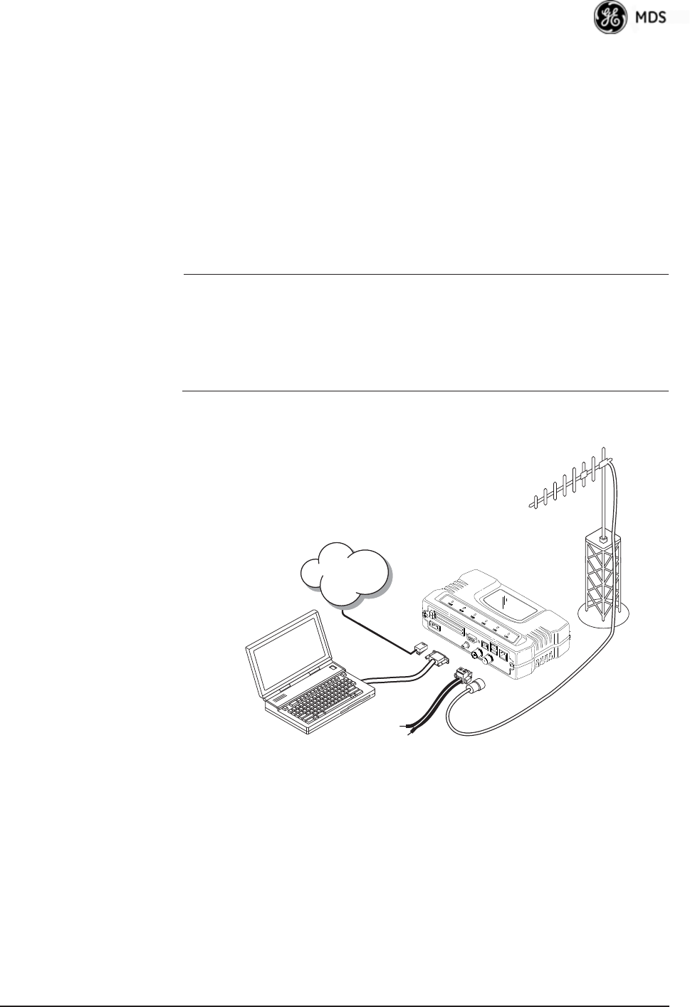
05-4446A01, Rev. E Mercury Reference Manual 163
5.1 INSTALLATION PLANNING
This section provides tips for selecting an appropriate site, choosing an
antenna system, and reducing the chance of harmful interference.
5.1.1 General Requirements
There are three main requirements for installing a transceiver—ade-
quate and stable primary power, a good antenna system, and the correct
interface between the transceiver and the data device. Figure 5-1 shows
a typical Remote installation.
NOTE: The transceiver’s network port supports 10BaseT and
100BaseT connections. Confirm that your hub/switch is
capable of auto-switching data rates.
To prevent excessive Ethernet traffic from degrading perfor-
mance, place the transceiver in a segment, or behind routers.
Invisible place holder
Figure 5-1. Typical Fixed Remote Installation
With a Directional Antenna
(Connect user data equipment to any compatible LAN Port)
Unit Dimensions
Figure 5-2 on Page 164 shows the dimensions of the transceiver case
and its mounting holes, and Figure 5-3 on Page 164 shows the dimen-
sions for mounting with factory-supplied brackets. If possible, choose a
POWER SUPPLY
13.8 VDC @ 580 mA (Max.)
(10.5–30 Vdc)
Negative Ground Only
COMPUTER RUNNING
TERMINAL PROGRAM
TRANSCEIVER
LOW-LOSS FEEDLINE
ANTENNA
SYSTEM
Network
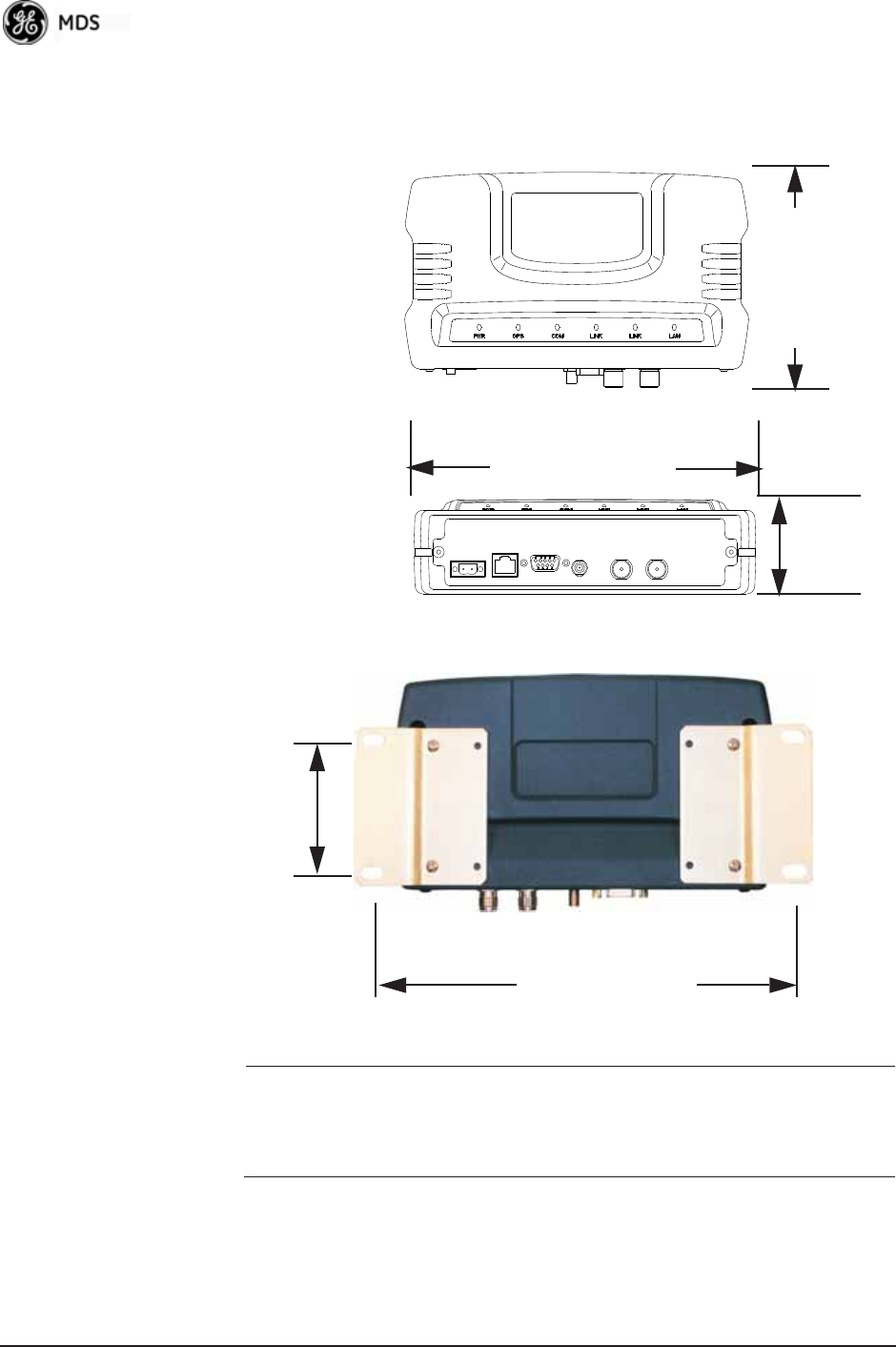
164 Mercury Reference Manual 05-4446A01, Rev. E
mounting location that provides easy access to the connectors on the end
of the radio and an unobstructed view of the LED status indicators.
Figure 5-2. Transceiver Dimensions
Invisible place holder
Invisible place holder
Figure 5-3. Mounting Bracket Dimensions (center to center)
NOTE: To prevent moisture from entering the radio, do not mount the
radio with the cable connectors pointing up. Also, dress all
cables to prevent moisture from running along the cables and
into the radio.
5.1.2 Site Selection
Suitable sites should provide:
• Protection from direct weather exposure
1.4
6.75 (17.15 cm)
4.5 (11.43 cm)
TOP
FRONT (3.56 cm)
VIEW
VIEW
2.75 (7 cm)
8 5/8 (21.8 cm)

05-4446A01, Rev. E Mercury Reference Manual 165
• A source of adequate and stable primary power
• Suitable entrances for antenna, interface, or other required
cabling
• An antenna location that provides a transmission path that is as
unobstructed as possible in the direction of the associated sta-
tion(s)
With the exception of the transmission path, you can quickly determine
these requirements. Radio signals travel primarily by line-of-sight, and
obstructions between the sending and receiving stations will affect
system performance. If you are not familiar with the effects of terrain
and other obstructions on radio transmission, the discussion below will
provide helpful background.
5.1.3 Terrain and Signal Strength
While the license-free bands offers many advantages for data transmis-
sion services, signal propagation is attenuated by obstructions such as
terrain, foliage, or buildings in the transmission path. A line-of-sight
transmission path between the central transceiver and its associated
remote site(s) is highly desirable and provides the most reliable commu-
nications link.
Much depends on the minimum signal strength that can be tolerated in
a given system. Although the exact figure will differ from one system to
another, a Received Signal Strength Indication (RSSI) of –80 dBm or
stronger will provide acceptable performance in most systems. While
the equipment will work at lower-strength signals, signals stronger than
– 77 dBm provide a fade margin of 15 dB to account for variations in
signal strength that might occur. You can measure RSSI with a terminal
connected to the COM1 port, or with an HTTP browser connected to the
LAN (Ethernet) connector. (See “Antenna Aiming (For Directional
Antennas)” on Page 158 for details.)
5.1.4 Antenna & Feedline Selection
NOTE: The transceiver must be installed by trained professional
installers, or factory trained technicians.
The following text will help the professional installer in the
proper methods of maintaining compliance with regulatory
ERP limits.
Antennas
The radio equipment can be installed with a number of antennas. The
exact style used depends on the physical size and layout of a system.
Contact your factory representative for specific recommendations on
antenna types and hardware sources.
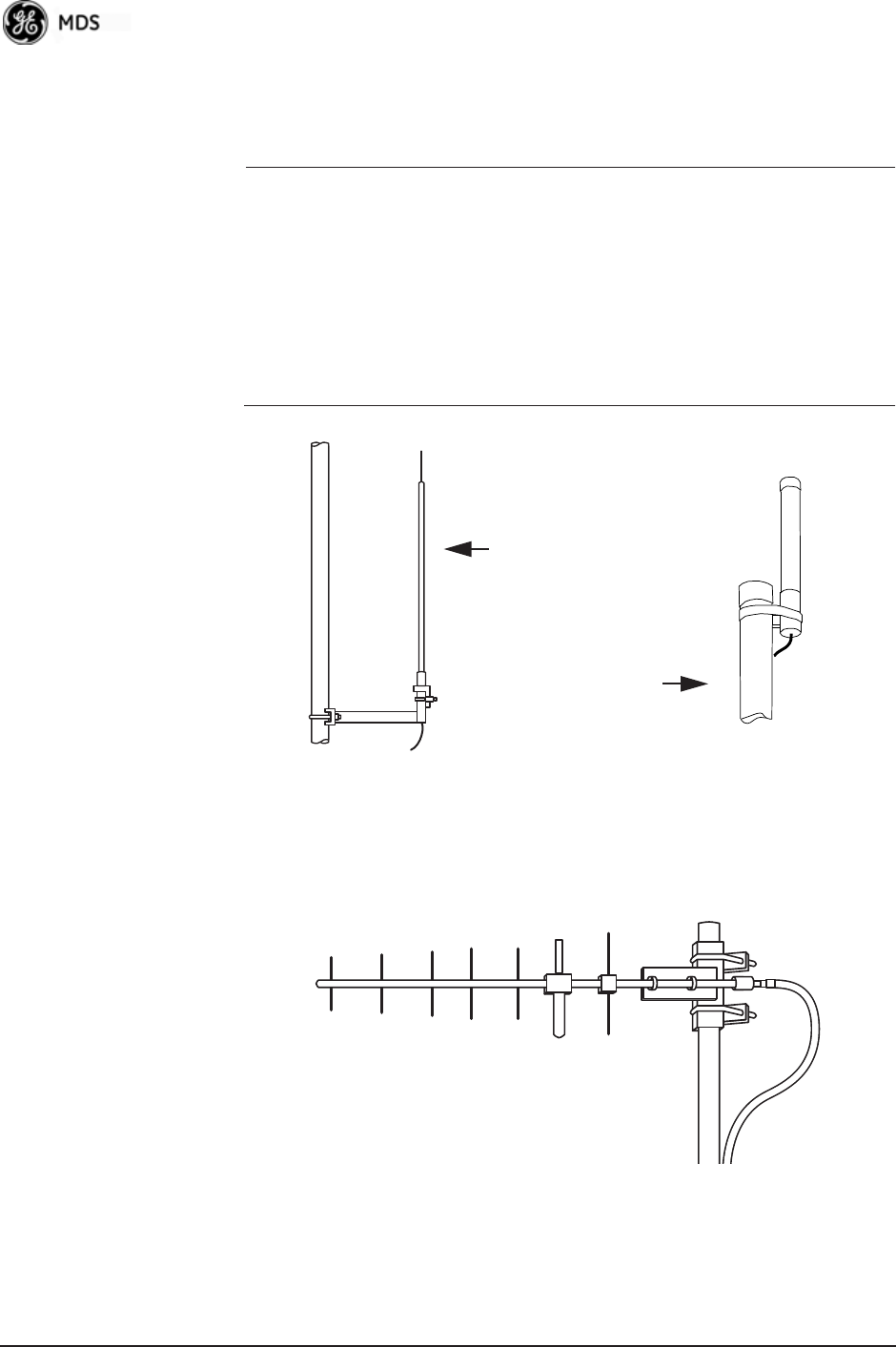
166 Mercury Reference Manual 05-4446A01, Rev. E
In general, an omnidirectional antenna (Figure 5-4) is used at the Access
Points and mobile Remote stations. This provides equal signal coverage
in all directions.
NOTE: Antenna polarization is important. If the wrong polarization is
used, a signal reduction of 20 dB or more will result. Most
systems using a gain-type omnidirectional antenna at Access
Point stations employ vertical polarization of the signal; there-
fore, the Remote antenna(s) must also be vertically polarized
(elements oriented perpendicular to the horizon).
When required, horizontally polarized omnidirectional
antennas are also available. Contact your factory representa-
tive for details.
Invisible place holder
Figure 5-4. Typical Omnidirectional Antennas
At fixed Remote sites, a directional Yagi antenna (Figure 5-5 on
Page 166) minimizes interference to and from other users. Antennas are
available from a number of manufacturers.
Invisible place holder
Figure 5-5. Typical Yagi Antenna (mounted to mast)
High-gain Type
Unity-gain Type

05-4446A01, Rev. E Mercury Reference Manual 167
Diversity Reception (RX2) Antenna Port
Functional on some models. The RX2 antenna port allows connection of
a second antenna to the transceiver for space diversity reception.
GPS Antennas
A number of GPS antennas (both active and passive) are available for
use with the transceivers. Consult your factory representative for more
information.
Feedlines
Carefully consider the choice of feedline used with the antenna. Avoid
poor-quality coaxial cables, as they degrade system performance for
both transmission and reception. A low-loss cable type such as Heliax®
is recommended that is suitable for the frequency of operation. Keep the
cable as short as possible to minimize signal loss.
Table 5-1 lists several types of popular feedlines and indicates the signal
losses (in dB) that result when using various lengths of cable at
900 MHz. The choice of cable depends on the required length, cost con-
siderations, and the acceptable amount of signal loss. Table 5-1 lists
several types of popular feedlines and indicates the signal losses (in dB)
that result when using various lengths of cable at 900 MHz. The choice
of cable depends on the required length, cost considerations, and the
acceptable amount of signal loss.
Table 5-1. Length vs. Loss in Coaxial Cables at 900 MHz
Cable Type
10 Feet
(3.05 m)
50 Feet
(15.24 m)
100 Feet
(30.48 m)
500 Feet
(152.4 m)
RG-214 .76 dB 3.8 dB 7.6 dB Unacceptable
Loss
LMR-400 0.39 dB 1.95 dB 3.90 dB Unacceptable
Loss
1/2 inch HELIAX 0.23 dB 1.15 dB 2.29 dB 11.45 dB
7/8 inch HELIAX 0.13 dB 0.64 dB 1.28 dB 6.40 dB
1-1/4 inch HELIAX 0.10 dB 0.48 dB 0.95 dB 4.75 dB
1-5/8 inch HELIAX 0.08 dB 0.40 dB 0.80 dB 4.00 dB
Table 5-2. Length vs. Loss in Coaxial Cables at 3600 MHz
Cable Type
10 Feet
(3.05 m)
50 Feet
(15.24 m)
100 Feet
(30.48 m)
500 Feet
(152.4 m)
RG-214 3.04 dB 15.2 dB Unacceptable
Loss
Unacceptable Loss
LMR-400 1.56 dB 7.8 dB 15.6 dB Unacceptable Loss

168 Mercury Reference Manual 05-4446A01, Rev. E
The tables below outline the minimum lengths of RG-214 coaxial cable
that must be used with common GE MDS omnidirectional antennas in
order to maintain compliance with FCC maximum limit of +36 dBi. If
other coaxial cable is used, make the appropriate changes in loss figures.
NOTE: The authority to operate the transceiver in the USA may be
void if antennas other than those approved by the FCC are
used. Contact your factory representative for additional
antenna information.
*Refer to Table 5-4 on Page 172 for allowable transceiver power set-
tings for each antenna type.
1/2 inch HELIAX 0.92 dB 4.6 dB 9.16 dB Unacceptable Loss
7/8 inch HELIAX 0.52 dB 2.56 dB 5.12 dB Unacceptable Loss
1-1/4 inch HELIAX 0.40 dB 1.92 dB 3.8 dB 19 dB
1-5/8 inch HELIAX 0.32 dB 1.6 dB 3.2 dB 16 dB
Table 5-2. Length vs. Loss in Coaxial Cables at 3600 MHz
Cable Type
10 Feet
(3.05 m)
50 Feet
(15.24 m)
100 Feet
(30.48 m)
500 Feet
(152.4 m)
Table 5-3. Feedline Length vs. Antenna Gain*
(Required for Regulatory Compliance)
Antenna
Gain (dBd)
Antenna
Gain (dBi)
Minimum Feedline
Loss (dB) that must
be introduced for
compliance
EIRP Level @
Min. Feedline
Length
Maxrad Antenna
Part No. (For 900
MHz Operation)
Unity (0 dB) 2.15 dBi No minimum length +32.15 dBm Omni #MFB900
3 dBd 5.15 dBi No minimum length +35.15 dBm Omni # MFB900
5 dBd 7.15 dBi 1.2 dB +35.95 dBm Omni # MFB900
6 dBd 8.15 dBi 2.2 dB +35.95 dBm Yagi # BMOY8903
9 dBd 11.15 dBi 7.15 dB +35.25 dBm Yagi # Z941
15.2 dBd 17.4 dBi 12 dB +35.4 dBm Andrew
DB878G90A-XY

05-4446A01, Rev. E Mercury Reference Manual 169
NOTE: There is no minimum feedline length required when a 6 dBi
gain or less antenna is used, as the EIRP will never exceed
36 dBm which is the maximum allowed, per FCC rules at 900
MHz. MDS 3650 models must not exceed 1-watt per MHz.
Units must comply with the information given on Page 172
and the associated antenna tables. Only the manufacturer or a
sub-contracted professional installer can adjust the trans-
ceiver’s RF output power.
The transceiver’s power output is factory set to maintain
compliance with the FCC’s Digital Transmission System
(DTS) Part 15 rules. These rules limit power to a maximum of
8 dBm/3 kHz, thus the transceiver is factory set to +29 dBm
(900 model); 23 dBm (3650 model). When calculating
maximum transceiver output for the 900 model, use +29 dBm
if the antenna gain is 6 dBi or less (36 dBm ERP). See How
Much Output Power Can be Used? below for power control
with higher gain antennas. Refer to Page 172 and the associ-
ated antenna tables for both 900 and 3650 model compliance.
5.1.5 How Much Output Power Can be Used?
The transceiver is normally configured at the factory for a nominal RF
power output of +29 dBm (900 model); +23 dBm (3650 model) this is
the maximum transmitter output power allowed under FCC rules. The
power must be decreased from this level if the antenna system gain
exceeds 6 dBi (900 model). The allowable level is dependent on the
antenna gain, feedline loss, and the transmitter output power setting.
NOTE: In some countries, the maximum allowable RF output might
be limited to less than the figures referenced here. Be sure to
check for and comply with the requirements for your area.
5.1.6 Conducting a Site Survey
If you are in doubt about the suitability of the radio sites in your system,
it is best to evaluate them before a permanent installation is underway.
You can do this with an on-the-air test (preferred method), or indirectly,
using path-study software.
An on-the-air test is preferred because it allows you to see firsthand the
factors involved at an installation site, and to directly observe the quality
of system operation. Even if a computer path study was conducted ear-
lier, perform this test to verify the predicted results.
Perform the test by first installing a radio and antenna at the proposed
Access Point (AP) station site (one-per-system). Then visit the Remote
site(s) with another transceiver (programmed as a remote) and a
hand-held antenna. (A PC with a network adapter can be connected to

170 Mercury Reference Manual 05-4446A01, Rev. E
each radio in the network to simulate data during this test, using the
PING command.)
With the hand-held antenna positioned near the proposed mounting
spot, a technician can check for synchronization with the Access Point
station (shown by a lit LINK LED on the front panel), then measure the
reported RSSI value. (See “Antenna Aiming (For Directional
Antennas)” on Page 158 for details.) If you cannot obtain adequate
signal strength, it might be necessary to mount the station antennas
higher, use higher gain antennas, select a different site, or install a
repeater station. To prepare the equipment for an on-the-air test, follow
the general installation procedures given in this guide and become
familiar with the operating instructions found in the CHAPTER-2
TABLETOP EVALUATION AND TEST SETUP on Page 21.
5.1.7 A Word About Radio Interference
The transceiver shares the radio-frequency spectrum with other services
and users. Completely error-free communications might not be achiev-
able in a given location, and some level of interference should be
expected. However, the radio’s flexible design and hopping techniques
should allow adequate performance as long as you carefully choose the
station location, configuration of radio parameters, and software/pro-
tocol techniques.
In general, keep the following points in mind when setting up your com-
munications network:
• Systems installed in rural areas are least likely to encounter interfer-
ence; those in suburban and urban environments are more likely to
be affected by other devices operating in the license-free frequency
band and by adjacent licensed services.
• Use a directional antenna at remote sites whenever possible.
Although these antennas may be more costly than omnidirectional
types, they confine the transmission and reception pattern to a com-
paratively narrow lobe, minimizing interference to (and from) sta-
tions located outside the pattern.
• If interference is suspected from a nearby licensed system (such as a
paging transmitter), it might be helpful to use horizontal polarization
of all antennas in the network. Because most other services use ver-
tical polarization in this band, you can achieve an additional 20 dB
of attenuation to interference by using horizontal polarization.
Another approach is to use a bandpass filter to attenuate all signals
outside the desired band.
• Multiple Access Point units can co-exist in proximity to each other
with no interference. The APs should be configured to operate in
TDD Sync Mode, where their transmissions are synchronized to
GPS timing. See “Protected Network Operation using Multiple

05-4446A01, Rev. E Mercury Reference Manual 171
APs” on Page 16. For additional isolation, separate directional
antennas with as much vertical or horizontal separation as is practi-
cal.
• The power output of all radios in a system should be set for the low-
est level necessary for reliable communications. This reduces the
chance of causing unnecessary interference to nearby systems and
also keeps power consumption to a minimum.
Configuring Mercury 3650 for Shared Spectrum Use
(Contention-Based Protocol)
While the Mercury 3650 has been designed to reduce the effects of inter-
ferers outside of the RF channel, cases may arrive where interferers may
cause undesired operation. In the case of WiMAX interferers, proper
configuration of the radio may reduce these effects.
The radio employs a WiMAX contention protocol that effectively
reduces the amount of interference the network may cause to other
co-located WiMAX networks using the same channel. In addition,
proper configuration of the radio will help to reduce the effects of other
WiMAX hardware attempting to do the same.
Remote radios receive scheduling information from a central base sta-
tion (AP). This scheduling information destined for a given remote
includes when to transmit, the duration of transmission, and modulation
selection. In the event the intended Remote unit is unable to receive or
interpret this information from the AP, the Remote will persist in receive
mode only.
The radio allows the installer to configure an Approved Access Point list
that contains the MAC addresses of desired AP radios in the network.
When an Access Point sends scheduling data to the Remote unit, the
Remote compares the MAC Address of the AP to this approved MAC
address list, and discards the scheduling information if it has originated
from a “foreign” network.
In order to maximize the performance of a shared network, the fol-
lowing configuration is recommended:
1. The Mercury 3650 network should be set to operate on the same
channel frequency as the network the channel is shared with. Slight
offsets in frequency between two collocated systems will cause
on-channel interference that is not decodable by either system.
Having both systems operate on the same frequency allows the radio
to decode WiMAX scheduling information from the interfering AP.
2. Configure the approved AP list using the AP Locations file as speci-
fied in the AP Location Push Config Menu on Page 60. After the
Remote unit has received scheduling information from the interfer-
ing network, it will compare the MAC address of this radio to its AP

172 Mercury Reference Manual 05-4446A01, Rev. E
Locations File. When the MAC address does not match, the radio
will ignore this information from the interfering AP and continue to
wait for valid scheduling information from an AP in the desired net-
work.
5.1.8 EIRP Compliance at 900 MHz
To determine the maximum allowable power setting of the radio, per-
form the following steps:
1. Determine the antenna system gain by subtracting the feedline loss
(in dB) from the antenna gain (in dBi). For example, if the antenna
gain is 9.5 dBi, and the feedline loss is 1.5 dB, the antenna system
gain would be 8 dB. (If the antenna system gain is 6 dB or less, no
power adjustment is required.)
2. Subtract the antenna system gain from 36 dBm (the maximum
allowable EIRP). The result indicates the maximum transmitter
power (in dBm) allowed under the rules. In the example above, this
is 28 dBm.
3. Set the transmitter power so that it does not exceed the maximum
level determined in Step 2.
(Main Menu>>Radio Configuration>>Transmit Power)
Refer to Table 5-4, which lists several antenna system gains and shows
the maximum allowable power setting of the radio. Note that a gain of
6 dB or less entitles you to operate the radio at full power output
–30 dBm.
For MDS 3650 units, refer also to the section titled EIRP Compliance at
3650 MHz below.
* Most antenna manufacturers rate antenna gain in dBd in their litera-
ture. To convert to dBi, add 2.15 dB.
** Must use with the appropriate length of feedline cable to reduce
transmitter power by at least 2 dB. Feedline loss varies by cable
type and length. To determine the loss for common lengths of feed-
line, see Table 5-1 on Page 167.
Table 5-4. Antenna Gain vs. Power Setpoint (900 MHz)
Antenna System Gain
(Antenna Gain in dBi*
minus Feedline Loss in dB)
Maximum Power Setting
(PWR command)
EIRP
(in dBm)
Omni 6 (or less) 29 35
Omni 11 25 36
Yagi 11 23 36
Half Parabolic 16 20 36
Panel 17.4** 20 36

05-4446A01, Rev. E Mercury Reference Manual 173
5.1.9 EIRP Compliance at 3650 MHz
To maintain regulatory compliance for Effective Isotropic Radiated
Power (EIRP) of 1-Watt per MHz, the following table of transmit
power settings must be observed for the listed bandwidths and antenna
types approved. Consult the factory for other antenna options of lower
gain.
The antennas used to support operation in this band must be fixed mounted.
Table 5-5. Antenna Gain vs. Power Setpoint (3650 MHz)
Antenna Gain
(dBi)
Radio Configuration
(Antenna Type/Radio Bandwidth))
Radio Power Setpoint
(dBm)
13 Omni Antenna, 1.75 MHz BW 22
13 Omni Antenna, 3.5 MHz BW 23
13 Omni Antenna, 5 MHz BW 23
13 Omni Antenna, 7 MHz BW 23
13 Omni Antenna, 10 MHz BW 23
13 Omni Antenna, 14 MHz BW 23
18 Panel Antenna, 1.75 MHz BW 17
18 Panel Antenna, 3.5 MHz BW 20
18 Panel Antenna, 5 MHz BW 22
18 Panel Antenna, 7 MHz BW 23
18 Panel Antenna, 10 MHz BW 23
18 Panel Antenna, 14 MHz BW 23

174 Mercury Reference Manual 05-4446A01, Rev. E
5.2 dBm-WATTS-VOLTS CONVERSION
CHART
Table 5-6 is provided as a convenience for determining the equivalent
voltage or wattage of an RF power expressed in dBm.
Table 5-6. dBm-Watts-Volts conversion—for 50 ohm systems
dBm V Po
+53 100.0 200W
+50 70.7 100W
+49 64.0 80W
+48 58.0 64W
+47 50.0 50W
+46 44.5 40W
+45 40.0 32W
+44 32.5 25W
+43 32.0 20W
+42 28.0 16W
+41 26.2 12.5W
+40 22.5 10W
+39 20.0 8W
+38 18.0 6.4W
+37 16.0 5W
+36 14.1 4W
+35 12.5 3.2W
+34 11.5 2.5W
+33 10.0 2W
+32 9.0 1.6W
+31 8.0 1.25W
+30 7.10 1.0W
+29 6.40 800mW
+28 5.80 640mW
+27 5.00 500mW
+26 4.45 400mW
+25 4.00 320mW
+24 3.55 250mW
+23 3.20 200mW
+22 2.80 160mW
+21 2.52 125mW
+20 2.25 100mW
+19 2.00 80mW
+18 1.80 64mW
+17 1.60 50mW
+16 1.41 40mW
+15 1.25 32mW
+14 1.15 25mW
+13 1.00 20mW
+12 .90 16mW
+11 .80 12.5mW
+10 .71 10mW
+9 .64 8mW
+8 .58 6.4mW
+7 .500 5mW
+6 .445 4mW
+5 .400 3.2mW
+4 .355 2.5mW
+3 .320 2.0mW
+2 .280 1.6mW
+1 .252 1.25mW
dBm V Po
0 .225 1.0mW
-1 .200 .80mW
-2 .180 .64mW
-3 .160 .50mW
-4 .141 .40mW
-5 .125 .32mW
-6 .115 .25mW
-7 .100 .20mW
-8 .090 .16mW
-9 .080 .125mW
-10 .071 .10mW
-11 .064
-12 .058
-13 .050
-14 .045
-15 .040
-16 .0355
dBm mV Po
-17 31.5
-18 28.5
-19 25.1
-20 22.5 .01mW
-21 20.0
-22 17.9
-23 15.9
-24 14.1
-25 12.8
-26 11.5
-27 10.0
-28 8.9
-29 8.0
-30 7.1 .001mW
-31 6.25
-32 5.8
-33 5.0
-34 4.5
-35 4.0
-36 3.5
-37 3.2
-38 2.85
-39 2.5
-40 2.25 .1W
-41 2.0
-42 1.8
-43 1.6
-44 1.4
-45 1.25
-46 1.18
-47 1.00
-48 0.90
dBm mV Po
-49 0.80
-50 0.71 .01W
-51 0.64
-52 0.57
-53 0.50
-54 0.45
-55 0.40
-56 0.351
-57 0.32
-58 0.286
-59 0.251
-60 0.225 .001W
-61 0.200
-62 0.180
-63 0.160
-64 0.141
dBm V Po
-65 128
-66 115
-67 100
-68 90
-69 80
-70 71 .1nW
-71 65
-72 58
-73 50
-74 45
-75 40
-76 35
-77 32
-78 29
-79 25
-80 22.5 .01nW
-81 20.0
-82 18.0
-83 16.0
-84 11.1
-85 12.9
-86 11.5
-87 10.0
-88 9.0
-89 8.0
-90 7.1 .001nW
-91 6.1
-92 5.75
-93 5.0
-94 4.5
-95 4.0
-96 3.51
-97 3.2
dBm V Po
-98 2.9
-99 2.51
-100 2.25 .1pW
-101 2.0
-102 1.8
-103 1.6
-104 1.41
-105 1.27
-106 1.18
dBm nV Po
-107 1000
-108 900
-109 800
-110 710 .01pW
-111 640
-112 580
-113 500
-114 450
-115 400
-116 355
-117 325
-118 285
-119 251
-120 225 .001pW
-121 200
-122 180
-123 160
-124 141
-125 128
-126 117
-127 100
-128 90
-129 80 .1˜W
-130 71
-131 61
-132 58
-133 50
-134 45
-135 40
-136 35
-137 33
-138 29
-139 25
-140 23 .01˜W

05-4446A01, Rev. E Mercury Reference Manual 175
6TECHNICAL REFERENCE
6 Chapter Counter Reset Paragraph
Contents
6.1 DATA INTERFACE CONNECTORS ........................................177
6.1.1 LAN Port ...................................................................................177
6.1.2 COM1 Port ............................................................................... 177
6.2 SPECIFICATIONS ................................................................... 178
6.3 NOTES ON SNMP...................................................................180
6.3.1 Overview .................................................................................. 180

176 Mercury Reference Manual 05-4446A01, Rev. E

05-4446A01, Rev. E Mercury Reference Manual 177
6.1 DATA INTERFACE CONNECTORS
Two types of data interface connectors are provided on the front panel
of the transceiver—an RJ-45 LAN port, and a DB-9 serial port (COM1),
which uses the RS-232 (EIA-232) signaling standard.
The transceiver meets U.S.A.’s FCC Part 15, Class A limits when used
with shielded data cables.
6.1.1 LAN Port
Use the transceiver’s LAN port to connect the radio to an Ethernet net-
work. The transceiver provides a data link to an Internet Protocol-based
(IP) network via the Access Point station. Each radio in the network
must have a unique IP address for the network to function properly.
• To connect a PC directly to the radio’s LAN port, an RJ-45 to
RJ-45 cross-over cable is required.
• To connect the radio to a Ethernet hub or bridge, use a
straight-through cable.
The connector uses the standard Ethernet RJ-45 cables and wiring. For
custom-made cables, use the pinout information in Figure 6-1 and
Table 6-1.
Figure 6-1. LAN Port (RJ-45) Pinout
(Viewed from the outside of the unit)
6.1.2 COM1 Port
The COM1 serial port is a standard DB-9 female connector. Connect a
PC to the transceiver via this port with a DB-9M to DB-9F
Table 6-1. LAN Port (IP/Ethernet)
Pin Functions Ref.
1 Transmit Data (TX) High
2 Transmit Data (TX) Low
3 Receive Data (RX) High
4 Unused
5 Unused
6 Receive Data (RX) Low
7 Unused
8 Unused
CAUTION
RADIO FREQUENCY
INTERFERENCE
POTENTIAL
1 2 3 4 5 6 7 8

178 Mercury Reference Manual 05-4446A01, Rev. E
“straight-through” cable. These cables are available commercially, or
may be constructed using the pinout information in Table 6-2.
6.2 SPECIFICATIONS
General
• Raw Bit Rate: from 600 kbps to 12.7 Mbps
• Frequency Bands: 902-928 MHz ISM band
3.65-3.7 GHz Registered FCC band
• Bandwidths: 900 model—1.75, 3.5 MHz
3650 model—1.75, 3.5, 5, 7 MHz
• Orthogonal Frequency Division Multiplexing (OFDM)
• 200 Carriers per Channel
• Available Configurations:
• Access Point: Ethernet, Serial, GPS
• Remote: Ethernet, Serial, GPS
Radio
• System Gain: 140 dB for 1.75 MHz channel, 137 dB for
3.5 MHz channel
• Carrier Power—AP: -30 to +29 dBm, RM: 0 to +29 dBm (900
models); +23 dBm max. (3650 model)
• RF Output Impedance: 50 Ohms
• Sensitivity and Signal Rate (see Table 6-3):
Table 6-3. Sensitivity and Signal Rate
Table 6-2. COM1 Port Pinout, DB-9F/RS-232 Interface
Pin Functions DCE
1 Unused
2 Receive Data (RXD) <—[Out
3 Transmit Data (TXD) —>[In
4 Unused
5 Signal Ground (GND)
6–9 Unused

05-4446A01, Rev. E Mercury Reference Manual 179
Note that the transceiver is a half-duplex radio, so maximum user
throughput is based on a configured or dynamic duty cycle, which is typ-
ically 50/50 indicating that half of the maximum throughput would be
available one way. The maximum user throughput is also based on high
protocol overhead from TCP/IP applications. For UDP applications,
these throughput numbers will increase.
Physical Interface
• Ethernet: 10/100BaseT, RJ-45
• Serial: 1,200 – 115,200 bps
• COM1: RS-232, DB-9F
• Antennas: TX/RX–TNC connector, GPS—SMA connector
• LED Indicators: PWR, COM1, LINK, LAN
Protocols (Pending—contact factory for details)
• Ethernet: IEEE 802.3, Spanning Tree (Bridging), VLAN, IGMP
• TCP/IP: DHCP, ICMP, UDP, TCP, ARP, Multicast, SNTP,
TFTP
• Serial: Encapsulation over IP (tunneling) for serial async multi-
drop protocols including MODBUS™, DNP.3, DF1, BSAP
GE MDS Cyber Security Suite, Level 1
• Encryption: AES-128.
• Authentication: 802.1x, RADIUS, EAP/TLS, PKI, PAP, CHAP
• Management: SSL, SSH, HTTPS
Management
• HTTP, HTTPS, TELNET, SSH, local console
• SNMPv1/v2/v3, MIB-II, Enterprise MIB
• SYSLOG
• MDS NETview MS™ compatible
Environmental
• Temperature: -40°C to +70°C (-40°F to +158°F)
• Humidity: 95% at 40°C (104°F) non-condensing
Electrical
• Input Power: 10-30 Vdc
• Current Consumption (nominal):
Mode Power 13.8 Vdc 24 Vdc
AP Transmit 25 W 1.8 A 1.0 A
AP Receive 8 W 579 mA 333 mA
RM Transmit 25W 1.8 mA 1.0 A
RM Receive 6.5W 471 mA 270 mA

180 Mercury Reference Manual 05-4446A01, Rev. E
Mechanical
• Case: Die Cast Aluminum
• Dimensions: 5.715 H x 20 W x 12.382 D cm. (2.25 H x 7.875 W
x 4.875 D in.)
• Weight: 1kg (2.2 lb.)
• Mounting options: Flat surface mount brackets, DIN rail, 19”
rack tray
External GPS PPS Option
Agency Approvals
• FCC Part 15.247 (DTS)—900 model
• FCC Part 90—3650 model
• CSA Class 1 Div. 2, (CSA C22.2-213-M1987 & CSA
C22.2-142-M1987) (UL1604 & UL916)
• IC RSS-210 “Issue 7”
NOTE: GE MDS products are manufactured under a quality system
certified to ISO 9001. GE MDS reserves the right to make
changes to specifications of products described in this manual
at any time without notice and without obligation to notify any
person of such changes.
6.3 NOTES ON SNMP
6.3.1 Overview
The firmware release described in this manual contains changes to the
transceiver’s SNMP Agent, several new MIB variables, and new Agent
configuration options. This guide reviews the changes and shows how
to properly configure the Agent to take advantage of these new features.
SNMPv3 Support
The updated SNMP Agent now supports SNMP version 3 (SNMPv3).
The SNMPv3 protocol introduces Authentication (MD5/SHA-1),
Parameter Minimum Maximum
Pulse Voltage (logic low) 0 V 1 V
Pulse Voltage (logic high) 1.7 V 10 V
Source Impedance (ohms) —200 Ω
Duty Cycle (ton) 0.0001% (1μsec) 50% (0.5 sec)
Operating Frequency 0.99999999 Hz
(-0.1 ppm error)
1.00000001 Hz
(+0.1 ppm error)
Module Clamping Voltage 2.7 V 3.3 V
Module Input Resistance 150 Ω (Vin >2.6 V) 10 kΩ (Vin < 2 V)
Input Hysteresis 7 mV N/A

05-4446A01, Rev. E Mercury Reference Manual 181
Encryption (DES), the USM User Table, and View-Based Access (refer
to RFC2574 for full details). The SNMP Agent has limited SNMPv3
support in the following areas:
• Only MD5 Authentication is supported (no SHA-1). SNMPv3
provides support for MD5 and SHA-1.
• Limited USM User Table Manipulation. The SNMP Agent
starts with 5 default accounts. New accounts can be added
(SNMPv3 adds new accounts by cloning existing ones), but
they will be volatile (will not survive a power-cycle).
New views cannot be configured on the SNMP Agent. Views are
inherited for new accounts from the account that was cloned.
The SNMP Agent uses one password pair (Authentication/Pri-
vacy) for all accounts. This means that when the passwords
change for one user, they change for all users.
SNMPv3 Accounts
The following default accounts are available for the SNMP Agent:
enc_mdsadmin—Read/write account using Authentication and Encryp-
tion.
auth_mdsadmin—Read/write account using Authentication.
enc_mdsviewer—Read only account using Authentication and Encryp-
tion.
auth_mdsviewer—Read only account using Authentication.
def_mdsviewer—Read only account with no Authentication or Encryp-
tion.
Context Names
The following Context Names are used (refer to RFC2574 for full
details):
Admin accounts: context_a/Viewer accounts: context_v.
All accounts share the same default passwords:
Authentication default password: MDSAuthPwd/Privacy default pass-
word: MDSPrivPwd.
Passwords can be changed either locally (via the console) or from an
SNMP Manager, depending on how the Agent is configured. If pass-
words are configured and managed locally, they are non-volatile and
will survive a power-cycle. If passwords are configured from an SNMP
manager, they will be reset to whatever has been stored for local man-
agement on power-cycle.

182 Mercury Reference Manual 05-4446A01, Rev. E
This behavior was chosen based on RFC specifications. The SNMP
Manager and Agent do not exchange passwords, but actually exchange
keys based on passwords. If the Manager changes the Agent’s password,
the Agent does not know the new password. The Agent only knows the
new key. In this case, only the Manager knows the new password. This
could cause problems if the Manager loses the password. If that hap-
pens, the Agent becomes unmanageable. Resetting the Agent’s pass-
words (and therefore keys) to what is stored in flash memory upon
power-cycle prevents the serious problem of losing the Agent’s pass-
words.
If passwords are managed locally, they can be changed on the Agent (via
the console). Any attempts to change the passwords for the Agent via an
SNMP Manager will fail when the Agent is in this mode. Locally
defined passwords will survive a power-cycle.
In either case, the SNMP Manager needs to know the initial passwords
being used in order to talk to the Agent. If the Agent’s passwords are
configured via the Manager, they can be changed from the Manager. If
the passwords are managed locally, then the Manager must be re-con-
figured with any password changes in order to continue talking to the
Agent.
Password-Mode Management Changes
When the password management mode is changed, the active passwords
used by the Agent may also change. Some common scenarios are dis-
cussed below:
Common Scenarios • Passwords are currently being handled by the Manager. The
assigned passwords are Microwave (Auth), and Rochester (Priv).
Configuration is changed to manage the passwords locally. The
passwords stored on the radio were Fairport (Auth), and
Churchville (Priv) (if local passwords have never been used,
then MDSAuthPwd and MDSPrivPwd are used). These pass-
words will now be used by the Agent to re-generate keys. The
Manager must know these passwords to talk to the Agent.
• Passwords are currently managed locally. The local passwords
are Fairport (Auth) and Churchville (Priv). Configuration is
changed to handle the passwords from the Manager. The same
passwords will continue to be used, but now the Manager can
change them.
• Passwords are currently managed locally. The local passwords
are Fairport (Auth) and Churchville (Priv). Passwords are changed
to Brighton (Auth) and Perinton (Priv). The Agent will immedi-
ately generate new keys based on these passwords and start
using them. The Manager will have to be re-configured to use
these new passwords.

05-4446A01, Rev. E Mercury Reference Manual 183
• Passwords are currently managed locally. The local passwords
are Fairport (Auth) and Churchville (Priv). Configuration is
changed to handle the passwords from the Manager. The Man-
ager changes the passwords to Brighton (Auth) and Perinton
(Priv). The radio is then rebooted. After a power-cycle, the radio
will use the passwords stored in flash memory, which are Fair-
port (Auth) and Churchville (Priv). The Manager must be re-con-
figured to use these new passwords.
Table 6-4. SNMP Traps (Sorted by Code)
SNMP Trap Severity Description
bootup(34) CRITICAL System Bootup
reboot(35) MAJOR User Selected Reboot
reprogStarted(36) INFORM Reprogramming Started
reprogCompleted(37) INFORM Reprogramming Completed
reprogFailed(38) MAJOR Reprogramming Failed
telnetLogin(39) MAJOR Telnet/SSH User login/logout
httpLogin(40) MAJOR HTTP User login/logout
logClear(41) INFORM Event Log Cleared
dhcpServer(42) INFORM DHCP server enabled/disabled
dhcpClient(43) INFORM DHCP client enabled/disabled
dhcpAddr(44) MINOR Obtained DHCP address
timeNotSet(45) INFORM Date/time not set
timeByUser(46) INFORM Date/time changed by user
timeFromServer(47) INFORM Date/time from server
consoleLogin(48) MAJOR Console user login/logout
httpLockdown(49) MAJOR HTTP Access locked down
parmChanged(50) INFORM Parameter changed
cfgscript(51) INFORM Configuration script generated/received
authKey(52) MAJOR Authorization key entered - valid/invalid
authDemo(53) MAJOR Demo authorization enabled/expired
maxDemos(54) CRITICAL Max demos reset/reached
modemRestart(55) MAJOR Modem restarted
internalError(56) MAJOR Internal error
gpsRestarted(57) MAJOR GPS Restarted
remoteConnection(58) INFORM Remote associated/disassociated
imageCopyStarted(59) INFORM Firmware image copy started
imageCopyComplete(60) INFORM Firmware image copy complete
imageCopyFailed(61) MAJOR Firmware image copy failed
connectionStatus(64) INFORM Connection status change
connAbort(65) MAJOR Connection aborted
authenticating(66) INFORM Authenticating to Access Point

184 Mercury Reference Manual 05-4446A01, Rev. E
association(67) MAJOR Associated to Access Point established/lost
redundLackRem(72) MAJOR Lack of associated remotes exceeded threshold for
P21 AP
redundRecvErr(73) MAJOR Packet receive errors exceeded threshold for P21
AP
redundForced(74) MAJOR P21 AP forced switchover
redundancySwitch(75) MAJOR P21 AP auto switchover
radioError(76) CRITICAL Radio error
procopen(77) MAJOR Proc filesystem access failed
procformat(78) MAJOR Unexpected proc filesystem format
csropen(79) MAJOR Failed to open CSR device
csrstatus(80) MAJOR CSR read failed
csrctrlsignal(81) MAJOR CSR write failed
bandwidthMismatch(83) INFORM Bandwidth of AP in Locations file does not match
this unit
gpsSync(84) INFORM GPS synchronized/lost sync
gpsTddSync(85) INFORM TDD synchronized/lost sync
tftpClientConn(86) INFORM TFTP Connection to Client Opened/Closed
tftpClientError(87) MAJOR Error in TFTP Transfer to Client
autoUpgrade(88) MAJOR Auto Firmware Upgrade Retry Scheduled/Starting
autoReboot(89) MAJOR Auto Firmware Boot Failed/Starting
certVerify(90) CRITICAL X.509 certificates loaded/failed
certChainVerify(91) CRITICAL Certificate chain verified/invalid
paTemp(92) MAJOR PowerAmp temperature Normal/Too hot
Table 6-4. SNMP Traps (Sorted by Code) (Continued)
SNMP Trap Severity Description

05-4446A01, Rev. E Mercury Reference Manual 185
7GLOSSARY OF TERMS
AND ABBREVIATIONS
7 Chapter Counter Reset Paragraph
If you are new to wireless IP/Ethernet systems, some of the terms used
in this manual might be unfamiliar. The following glossary explains
many of these terms and will prove helpful in understanding the opera-
tion of your radio network. Some of these terms do not appear in the
manual, but are often encountered in the wireless industry, and are there-
fore provided for completeness.
Access Point (AP)—The transceiver in the network that provides syn-
chronization information to one or more associated Remote units.
See “Network Configuration Menu” on Page 45.
AGC—Automatic Gain Control
Antenna System Gain—A figure, normally expressed in dB, repre-
senting the power increase resulting from the use of a gain-type antenna.
System losses (from the feedline and coaxial connectors, for example)
are subtracted from this figure to calculate the total antenna system gain.
AP—See Access Point
Association—Condition in which the frequency hopping pattern of the
Remote is synchronized with the Access Point station, and the Remote
is ready to pass traffic.
Authorization Key—Alphanumeric string (code) that is used to enable
additional capabilities in the transceiver.
Bit—The smallest unit of digital data, often represented by a one or a
zero. Eight bits usually comprise a byte.
Bits-per-second—See BPS.
BPDU—Bridge Protocol Data Units
BPS—Bits-per-second (bps). A measure of the information transfer rate
of digital data across a communication channel.
Byte—A string of digital data made up of eight data bits.
CSMA/CA—Carrier Sense Multiple Access/Collision Avoidance
CSMA/CD—Carrier Sense Multiple Access/Collision Detection
Cyclic Redundancy Check (CRC)—A technique used to verify data
integrity. It is based on an algorithm which generates a value derived

186 Mercury Reference Manual 05-4446A01, Rev. E
from the number and order of bits in a data string. This value is com-
pared with a locally-generated value and a match indicates that the mes-
sage is unchanged, and therefore valid.
Data Circuit-terminating Equipment—See DCE.
Data Communications Equipment—See DCE.
Datagram—A data string consisting of an IP header and the IP message
within.
Data Terminal Equipment—See DTE.
dBd—Decibels (dipole antenna).
dBi—Decibels referenced to an “ideal” isotropic radiator in free space.
Frequently used to express antenna gain.
dBm—Decibels referenced to one milliwatt. An absolute unit used to
measure signal power, as in transmitter power output, or received signal
strength.
DCE—Data Circuit-terminating Equipment (or Data Communications
Equipment). In data communications terminology, this is the “modem”
side of a computer-to-modem connection. COM1 Port of the transceiver
is set as DCE.
Decibel (dB)—A measure of the ratio between two signal levels. Fre-
quently used to express the gain (or loss) of a system.
Delimiter—A flag that marks the beginning and end of a data packet.
Device Mode—The operating mode/role of a transceiver (Access Point
or Remote) in a wireless network.
DHCP (Dynamic Host Configuration Protocol)—An Internet stan-
dard that allows a client (i.e. any computer or network device) to obtain
an IP address from a server on the network. This allows network admin-
istrators to avoid the tedious process of manually configuring and man-
aging IP addresses for a large number of users and devices. When a
network device powers on, if it is configured to use DHCP, it will con-
tact a DHCP server on the network and request an IP address.
The DHCP server will provide an address from a pool of addresses allo-
cated by the network administrator. The network device may use this
address on a “time lease” basis or indefinitely depending on the policy
set by the network administrator. The DHCP server can restrict alloca-
tion of IP addresses based on security policies. An Access Point may be
configured by the system administrator to act as a DHCP server if one
is not available on the wired network.

05-4446A01, Rev. E Mercury Reference Manual 187
Digital Signal Processing—See DSP.
DSP—Digital Signal Processing. DSP circuitry is responsible for the
most critical real-time tasks; primarily modulation, demodulation, and
servicing of the data port.
DTE—Data Terminal Equipment. A device that provides data in the
form of digital signals at its output. Connects to the DCE device.
Encapsulation—Process in by which, a complete data packet, such as
MODBUS™ frame or any other polled asynchronous protocol frame, is
placed in the data portion of another protocol frame (in this case IP) to
be transported over a network. Typically this action is done at the trans-
mitting end, before being sent as an IP packet to a network. A similar
reversed process is applied at the other end of the network extracting the
data from the IP envelope, resulting in the original packet in the original
protocol.
Endpoint—Data equipment connected to the Ethernet port of the radio.
Equalization—The process of reducing the effects of amplitude, fre-
quency or phase distortion with compensating networks.
Fade Margin—The greatest tolerable reduction in average received
signal strength that will be anticipated under most conditions. Provides
an allowance for reduced signal strength due to multipath, slight antenna
movement or changing atmospheric losses. A fade margin of 15 to 20
dB is usually sufficient in most systems.
Fragmentation—A technique used for breaking a large message down
into smaller parts so it can be accommodated by a less capable media.
Frame—A segment of data that adheres to a specific data protocol and
contains definite start and end points. It provides a method of synchro-
nizing transmissions.
Frequency Hopping—The spread spectrum technique used by the
transceiver, where two or more associated radios change their operating
frequencies many times per second using a set pattern. Since the pattern
appears to jump around, it is said to “hop” from one frequency to
another.
GPS—Global Positioning System. A constellation of orbiting satellites
used for navigation and timing data. Although 24 satellites are normally
active, a number of spares are also available in case of malfunction.
Originally designed for military applications by the U.S. Department of
Defense, GPS was released for civilian use in the 1980s. GPS satellites
operate in the vicinity of the “L” frequency band (1500 MHz).
Hardware Flow Control—A transceiver feature used to prevent data
buffer overruns when handling high-speed data from the connected data

188 Mercury Reference Manual 05-4446A01, Rev. E
communications device. When the buffer approaches overflow, the
radio drops the clear-to-send (CTS) line, that instructs the connected
device to delay further transmission until CTS again returns to the high
state.
Host Computer—The computer installed at the master station site, that
controls the collection of data from one or more remote sites.
HTTP—Hypertext Transfer Protocol
ICMP—Internet Control Message Protocol
IGMP (Internet Gateway Management Protocol)—Ethernet level
protocol used by routers and similar devices to manage the distribution
of multicast addresses in a network.
IEEE—Institute of Electrical and Electronic Engineers
IEEE 802.1Q—A standard for Ethernet framing which adds a four-byte
tag after the Ethernet header. The four-byte tag contains a VLAN ID and
a IEEE 802.1P priority value.
IEEE 802.1X—A standard for performing authentication and port
blocking. The 802.1X port/device denies access to the network until the
client device has authenticated itself.
Image (File)—Data file that contains the operating system and other
essential resources for the basic operation of the radio’s CPU.
LAN—Local Area Network
Latency—The delay (usually expressed in milliseconds) between when
data is applied at the transmit port at one radio, until it appears at the
receive port at the other radio.
MAC—Media Access Controller
MD5—A highly secure data encoding scheme. MD5 is a one-way hash
algorithm that takes any length of data and produces a 128 bit “finger-
print.” This fingerprint is “non-reversible,” it is computationally infea-
sible to determine the file based on the fingerprint. For more details
review “RFC 1321” available on the Internet.
MIB—Management Information Base
Microcontroller Unit—See MCU.
Mobility—Refers to a station that moves about while maintaining
active connections with the network. Mobility generally implies phys-
ical motion. The movement of the station is not limited to a specific net-
work and IP subnet. In order for a station to be mobile it must establish

05-4446A01, Rev. E Mercury Reference Manual 189
and tear down connections with various access points as it moves
through the access points' territory.
Mode—See Device Mode.
MTBF—Mean-Time Between Failures
Multiple Address System (MAS)—See Point-Multipoint System.
NMEA—National Marine Electronics Association. National body that
established a protocol for interfacing GPS data between electronic
equipment.
Network Name—User-selectable alphanumeric string that is used to
identify a group of radio units that form a communications network. The
Access Point and all Remotes within a given system should have the
same network address.
Network-Wide Diagnostics—An advanced method of controlling and
interrogating GE MDS radios in a radio network.
NTP—Network Time Protocol
Packet—The basic unit of data carried on a link layer. On an IP network,
this refers to an entire IP datagram or a fragment thereof.
PING—Packet INternet Groper. Diagnostic message generally used to
test reachability of a network device, either over a wired or wireless net-
work.
PKI—Private Key Infrastructure. A set of policies and technologies
needed to create, store, and distribute Public Key Certificates used to
protect the security of network communications.
Point-to-Multipoint System—A radio communications network or
system designed with a central control station that exchanges data with
a number of remote locations equipped with terminal equipment.
Poll—A request for data issued from the host computer (or master PLC)
to a remote device.
Portability—A station is considered connected when it has successfully
authenticated and associated with an access point. A station is consid-
ered authenticated when it has agreed with the access point on the type
of encryption that will be used for data packets traveling between them.
The process of association causes a station to be bound to an access
point and allows it to receive and transmit packets to and from the access
point. In order for a station to be associated it must first authenticate
with the access point. The authentication and association processes
occur automatically without user intervention.

190 Mercury Reference Manual 05-4446A01, Rev. E
Portability refers to the ability of a station to connect to an access point
from multiple locations without the need to reconfigure the network set-
tings. For example, a remote transceiver that is connected to an access
point may be turned off, moved to new site, turned back on, and,
assuming the right information is entered, can immediately reconnect to
the access point without user intervention.
PLC—Programmable Logic Controller. A dedicated microprocessor
configured for a specific application with discrete inputs and outputs. It
can serve as a host or as an RTU.
PuTTY—A free implementation of Telnet and SSH for Win32 and
Unix platforms. It is written and maintained primarily by Simon
Tatham. Refer to http://www.pobox.com/~anakin/ for more information.
RADIUS—Remote Authentication Dial In User Service. An authenti-
cation, authorization, and accounting protocol used to secure remote
access to a device or network.
Remote—A transceiver in a network that communicates with an asso-
ciated Access Point.
Remote Terminal Unit—See RTU.
RFI—Radio Frequency Interference
Roaming—A station's ability to automatically switch its wireless con-
nection between various access points (APs) as the need arises. A station
may roam from one AP to another because the signal strength or quality
of the current AP has degraded below what another AP can provide.
Roaming may also be employed in conjunction with Portability where
the station has been moved beyond the range of the original AP to which
it was connected. As the station comes in range of a new AP, it will
switch its connection to the stronger signal. Roaming refers to a station's
logical, not necessarily physical, move between access points within a
specific network and IP subnet.
RSSI—Received Signal Strength Indicator
RTU—Remote Terminal Unit. A data collection device installed at a
remote radio site.
SCADA—Supervisory Control And Data Acquisition. An overall term
for the functions commonly provided through an MAS radio system.
SNMP—Simple Network Management Protocol
SNR—Signal-to-Noise Ratio. A measurement of the desired signal to
ambient noise levels.This measurement provides a relative indication of
signal quality. Because this is a relative number, higher signal-to-noise
ratios indicate improved performance.

05-4446A01, Rev. E Mercury Reference Manual 191
SNTP—Simple Network Time Protocol
SSL—Secure Socket Layer
SSH—Secure Shell
STP—Spanning Tree Protocol
Standing-Wave Ratio—See SWR.
SWR—Standing-Wave Ratio. A parameter related to the ratio between
forward transmitter power and the reflected power from the antenna
system. As a general guideline, reflected power should not exceed 10%
of the forward power (≈ 2:1 SWR).
TCP—Transmission Control Protocol
TFTP—Trivial File Transfer Protocol
Trap Manager—Software that collects SNMP traps for display or log-
ging of events.
UDP—User Datagram Protocol
UTP—Unshielded Twisted Pair
VLAN—Virtual Local Area Network. A network configuration
employing IEEE 802.1Q tagging, which allows multiple groups of
devices to share the same physical medium while on separate broadcast
domains.

192 Mercury Reference Manual 05-4446A01, Rev. E

05-4446A01, Rev. E Mercury Reference Manual I-1
INDEX
Numerics
100BaseT 56, 163
10BaseT 56, 163
16QAM 75
64QAM 75
802.11b 12
A
Access Point (AP), defined 185
accessories 19
Active Scanning, defined 185
adapter
TNC Male-to-N Female 19
Adaptive
Modulation 73
Split 74
Add
Associated Remotes 97
Remote 97
Address to Ping 135
Advanced
Configuration 66
Control 71
AES encryption 4
agency approvals 180
alarm conditions 154
correcting 155
Alarmed 152
alarms 153
Altitude 116
antenna
900 MHz 5
aiming 158
cross-polarization 15
directional 5, 170
for repeater stations 15
GPS 5, 167
receiving 19
minimizing interference 15
Minimum Feedline Length versus Antenna Gain 168
omni-directional 5, 14, 19, 166
polarization 166
selection 165
SWR check 157
system gain
defined 185
vs. power output setting 172
vertical separation 15
Yagi 14, 19, 166
AP
current name 144
Location Info Config 46
locations 60—64
application
IP-to-Serial 83
Mixed-Modes 87
Point-to-Multipoint Serial-to-Serial 84
Point-to-Point Serial-to-Serial 83
Serial Port 87
approvals
agency 180
Approved Remotes 96
ARQ 74
Block Lifetime 74
Block Size 74
Receiver Delay 74
Transmitter Delay 74
Window Size 74
Associated 152
Remotes 43, 118
association
defined 185
process 117
attenuation 24
Auth Server
Address 99
Port 99
Shared Secret 99
Auth Traps Status 60
Authenticating 152
authentication
device 97
user 98
Authorization
Codes 124, 136
Key 136
defined 185
Authorized Features 136
Auto Firmware Upgrade 125
Automatic Repeat Request 74
Auto-Upgrade/Remote-Reboot 138
Average
RSSI 122
SNR 122
B
Backhaul
for serial radio networks 11
Network 11
bandpass filter 170
baud rate 79, 82
console 76
serial data 76
Begin Wizard 78
Bit, defined 185
Bits-per-second (bps), defined 185
BPDU 58
defined 185
BPS, defined 185
BPSK 75
Bridge
Configuration 46
Forward Delay 58
Hello Time 58
Priority 58
Protocol Data Unit 58
Bridge Status 111
Buffer Size 79, 81, 82
BW 63
Byte Format 79
byte format 80, 82
bytes
defined 185
received 115
sent 115

I-2 Mercury Reference Manual 05-4446A01, Rev. E
C
cable
crossover 36, 38, 177
EIA-232 Shielded Data 19
Ethernet crossover 14, 25, 39
Ethernet RJ-45 Crossover 19
Ethernet RJ-45 Straight-thru 19
feedlines 167
serial communications 25, 37
straight-through 38, 39, 177
certificate
files 97
type 101
Certificate Filename 101
Change
Admin Password 95
Guest Password 95
channel
selection 71
single frequency 70
type 74
CHANNELS 63
clear
Ethernet statistics 115
Event Log 113
MDS wireless statistics 115
Collocating Multiple Radio Networks 16
Commit Changes and Exit Wizard 80, 81, 82
communication
peer-to-peer 10
Compression 145
Computer
host, defined 188
Config
filename 133
configuration 25, 81
advanced 66
defaults 25
DHCP server 50
editing files 134
Ethernet Port 56
file 25, 149
IP address 53
network 45
P23 8
protected network 8
radio parameters 65—88
RADIUS 99
redundant 8
script 124, 131
SNMP Agent 58
TCP Mode 81
UDP mode 79
Connecting 152
Connection Status 43, 119, 121, 143
connectionware 145
connector
descriptions 177
Ethernet 10
console baud rate 76, 109
Contact 110
context names 181
Corrected FEC Count 123, 144
cost of deployment 12
Count 135
CRC (Cyclic Redundancy Check), defined 185
CSMA
CA, defined 185
CD, defined 185
Current Alarms 113
Current AP 70
Eth Address 119
IP Address 119
Name 119, 121, 144
Current IP
Address 42, 50, 53
Gateway 50, 53
Netmask 50, 53
Cyclic Prefix 74
D
data
baud rate 81
buffering 77
compression 73
encryption 96
VLAN ID 49
VLAN Subnet Config 49
Datagram, defined 186
Date 109
Format 109
dB, defined 186
dBd, defined 186
dBi, defined 186
dBm
defined 186
watts-volts conversion 174
DCE, defined 186
Default Route IF 49
defaults
resetting 137
Delete
All Remotes 97
Remote 97
Delimiter, defined 186
deployment costs 12
Description 110
Device
Auth Mode 96
Authentication 97
Information 45
Menu 109
Mode 42
defined 186
Name 42, 110, 135
Security Menu 93
Status 42, 118, 152
messages 152
DHCP 53
defined 186
DNS address 52
ending address 52
Netmask 52
Server 49
Config 49
Configuration 46, 47
Status 52
starting address 52
WINS address 52
Diagnostic Tools 153
dimensions 163

05-4446A01, Rev. E Mercury Reference Manual I-3
DIN Rail Mounting Bracket 20
DKEY command 157
Downlink 144
Percentage 74
DSP (Digital Signal Processing), defined 187
DTE
defined 187
DUR 63
E
EIA-232 13
Embedded Management System 25
Enable Filtering 57
encapsulation
defined 187
serial 76
transparent 76
encryption 5
AES 4
Phrase 96
Endpoint
defined 187
Equalization, defined 187
Ethernet
filtering configuration 57
Port Config 46
port enable 56
port follows association 57
port phy rate 56
event
Alarms 154
Critical 154
Informational 154
Major 154
Minor 154
Temporary Informational 154
Event Log 111, 114, 152, 153, 154, 155
clear 113
filename 113
host address 113
Menu 113
send 113
view 113
events 153
F
factory defaults
resetting 137
Fade Margin 187
FEC 73
count
corrected 123, 144
total 123, 144
uncorrected 123, 144
Total 144
feedline
selection 165, 167
file
certificate 97
MIB 33
Filename 127
filtering
enable 57
firmware
automatic upgrade 125
current 128
filename 130
for Upgrade 138
installing 129
upgrade 130, 138
version 43, 125
Flow Control
hardware, defined 187
Force
Switchover 103
Fragmentation
defined 187
frame
defined 187
duration 70
Free Run 24, 27, 29
frequency
control 66
hopping, defined 187
mode 26, 68
offset
RX 144
TX 144
fuse 19
G
gain
antenna, defined 185
gateway
current IP 53
Glossary 185—191
GPS
antenna 167
Configuration 45
defined 187
external GPS PPS option 9, 180
Firmware Version 116
information 116
latitude 63
longitude 63
Precise Positioning Service 116
pseudo-random noise 116
receiver 42
satellite fix 64
Serial Number 116
Status 111
Menu 116
Streaming Configuration 107
time of day 64
timing signals 42
to Console Baud Rate 107
UDP Server IP Address 107
UDP Server UDP Port 107
GROUP 63
H
hand-off 71
Signal and Distance 71
Signal, Distance, and Bearing 71
Strict Connection 71
Strict Distance 71
Strict Signal 71
Hardware
Event Triggers 103, 105
flow control, defined 187

I-4 Mercury Reference Manual 05-4446A01, Rev. E
Version 43
hop
pattern 70, 145
pattern offset 70
Hopping
frequency, defined 187
Host
computer 86
computer, defined 188
HTTP
Auth Mode 94
defined 188
Mode 94
HyperTerminal 36, 37
Hysteresis Margin 73, 75
I
IANA 77
ICMP
defined 188
IEEE
802.1Q 48, 49, 188
802.1X 188
defined 188
IEEE 802.1x
Device Authentication 4, 51, 97
IETF standard RFC1213 58
IGMP 77
defined 188
Image
Copy 128
file, defined 188
Verify 128
iNET II, differences of 158
Init/Hardware Error 105
Installation
antenna & feedline 165
feedline selection 167
general information 5
mobile 9
planning 163
requirements 163
site selection 164
site survey 169
Interference 170
inter-frame packet delay 82
Internal Radio Status 111
Menu 120
Internet
Assigned Numbers Authority 77
Control Message Protocol, defined 188
Inter-Packet Delay 79, 81, 82
IP 12, 50
Address 26, 42, 53, 134
Configuration 47
Mode 49, 50, 53
Configuration 46
current
address 50, 53
gateway 50
netmask 50
gateway 53, 134
netmask 53
Protocol 80
static
address 49
netmask 49
tunneling 76
K
KEY
command 157
transmitter, for antenna SWR check 157
L
Lack of Associated Remotes Exceeded Threshold 104, 105
Menu 106
Lack of Remotes for 106
LAN
defined 188
wireless 10, 12
LAT 63
Latency, defined 188
Latitude 116
LED
COM1 30
LAN 29, 38, 39, 150
LINK 29, 30, 150, 159, 170
PWR 29, 30, 114, 150, 154, 155
use during troubleshooting 149
Local
Area Network, defined 188
Console 36
session 37
Location 110, 135
logged events 155
LONG 63
Longitude 116
Lost Carrier Detected 115, 153
M
MAC 63
ADDR 144
Main Menu 43
Maintenance/Tools 45
Menu 123
Manage Certificates 93
Management
VLAN ID 49
VLAN Mode 49
VLAN Subnet Config 49
Management System 25, 76, 130
as a troubleshooting tool 150
user interfaces 33
manuals
Reference Manual 3
Start-Up Guide 3
margin
hysteresis 75
protection 75
Max
Modulation 74
Transmit Power 66
Max Remotes 96
Maximum Receive Errors 106
MD5, defined 188
MDS Security Suite 17
measurements
radio 157
Media Access Controller, defined 188

05-4446A01, Rev. E Mercury Reference Manual I-5
MIB
defined 188
files 33, 58
version II 58
mobile 9
Mobility
defined 188
MODBUS 88
ASCII 90
RTU 90
Modbus
TCP Server 88
Mode 63, 79
Device, defined 186
mixed 86
Model 109
modulation protection 75
MTBF, defined 189
multicast addressing 77
N
NAME 63
NEMA 12
netmask
current IP 53
network
Administrator 9
Configuration 44
coverage 145
design 14
antennas 15
collocating multiple radio networks 16
name 15
repeaters 14
using multiple Access Points 16
Using the AP as a Store-and-Forward Packet
Repeater 15
Using two transceivers to form a repeater station 14
Event Triggers 103, 104
Interface
Config 46
Error 104
LAN 10
name 17, 23, 26, 66, 145
defined 189
tabletop 23
Time Protocol (NTP), defined 189
WAN 1 0
-wide diagnostics 189
NTP (Network Time Protocol), defined 189
Number of Satellites 116
O
OFDM 4
OFFSET 63
optimizing
radio performance 140
Orthogonal Frequency Division Multiplexing 4
Outgoing Connections Inactivity Timeout 81
P
P23 8
Packet
defined 189
Receive Errors Exceeded Threshold 104, 106
Menu 106
Size 135
Statistics 111, 114, 153
packets
dropped 115, 153
received 115
sent 115
password
admin 95
guest 95
Pattern Offset 145
PC
connection to transceiver 25
host 86
peer-to-peer communications 10
Performance
Information 45
Trend 111
PING 23, 30, 123, 170
address 135
defined 189
utility 124
PKI 189
PLC 13
defined 190
point-to-multipoint 16
defined 189
Point-to-Point
LAN Extension 11
Link 11
Poll, defined 189
port
access 48, 49
COM1 13, 25, 26, 27, 28, 33, 36, 38, 44, 76, 83, 88, 130,
165, 177
COM2 26, 83
Ethernet 23, 48, 49
GPS antenna 27, 29
IP 83
LAN 25, 26, 27, 28, 33, 36, 38, 39, 53, 76, 130, 165, 177
PWR 27, 28
RX2 27, 29, 167
serial 12
trunk 49
TX/RX1 antenna 27, 29
Portability, defined 189
power
connector 24
how much can be used 169
primary 24
transmitter power output 157
PPS 116
Precise Positioning Service 116
PRN 116
Programmable Logic Controller 13
Protection Margin 73, 75
protocol
DHCP 53
HTTP 33
HTTPS 33
ICMP 48
defined 188
IP 12, 26, 50, 76
SNMP 33, 48, 50, 58, 180
defined 190

I-6 Mercury Reference Manual 05-4446A01, Rev. E
SNTP 46, 191
SSH 33, 36
STP, defined 191
Syslog 113
TCP 76, 77, 81, 83, 86
defined 191
Telnet 33, 36, 38, 48
TFTP 48, 129
defined 191
UDP 76, 77, 83, 86
defined 191
Pseudo-Random Noise 116
PuTTY usage 41
defined 190
Q
QoS 4
QPSK 75
Quality of Service 4
R
Radio
Configuration 44
Details 122
Event Triggers 103, 104
Frequency Interference 17
interference 170
Mode 139
performance optimization 140
Remote, defined 190
Test 125
RADIUS 190
configuration 93, 99
User Auth Mode 99
range, transmission 12
ranging 152
Read Community String 59
reboot
Device 128
on upgrade 138
Remotes 138
receive
errors 115, 153
power 66
Received Signal Strength Indicator 24, 165
defined 190
Redundancy
Configuration 45, 103
Options 103, 105
Using multiple Access Points 16
Remote
add 97
associated 97
approved 96
Database 118
delete 97
all 97
Max 6
Performance Database 118
radio, defined 190
Standard 6
Terminal Unit 13
defined 190
view approved 97
Repeater 14
antennas 15
Network Name 15
Using the AP as a Store-and-Forward Packet Repeater 15
Using two transceivers to form a repeater station 14
Reprogramming 124
Menu 126
Reset to Factory Defaults 124, 137
Retries 153
Retrieve
Certificate 101
File 128, 134
Retry errors 153
RF
bandwidth 26, 69
Output Power 26
power output level 24
RFI 17
defined 190
Roaming, defined 190
RSSI 24, 122, 143, 144, 158, 165
average 122
defined 190
RTU 13, 83, 87
defined 190
RX
Frequency Offset 123, 144
IP Port 79
S
satellite
fix status 43, 116
number of 116
SCADA 12, 13, 77
defined 190
Scanning 152
script
configuration 124
security
Configuration 45
Menu 92
device level 97
general information 5
monitoring 13
password 25
risk management 18
suite 17
wireless access 97
Send
Event Log 113
file 134
GPS via UDP 107
Serial
Configuration Wizard 77
data baud rate 76
encapsulation 76
Number 43, 109
Port
Configuration 44
radio networks, backhaul 11
server
status 52
time 114
signal
strength 165
-to-noise ratio 116

05-4446A01, Rev. E Mercury Reference Manual I-7
defined 190
Simple Network
Management Protocol, defined 190
Time Protocol 64
defined 191
Single
channel operation 24
Frequency Channel 26, 70
SINGLE_CHAN 63
Site selection 164
SNMP 33, 50
Agent Config 46
defined 190
Mode 60
traps 183
usage 180
V3 Passwords 60
SNMPv3 180
accounts 181
SNR 73, 116, 122, 144
average 122
defined 190
max 75
min 75
range 75
SNTP
defined 191
Server 46
configuration 64
Spanning Tree Protocol, defined 191
Spectrum Analyzer Mode 140
spread-spectrum transmission 5
SSH 36, 98
Access 94
defined 191
SSL, defined 191
Standing Wave Ratio 191
Starting
Information Screen 38, 44
Static IP
Address 49, 50, 53
Gateway 54
Netmask 49, 50, 53
Status 42, 79, 80, 81, 82
alarmed 152
associated 152
authenticating 152
connecting 152
scanning 152
STP, defined 191
Stream GPS to Console 107
subnet 53
SWR 157, 191
defined 191
performance optimization 157
Syslog Server Address 113
system gain, antenna (defined) 185
T
tabletop network 23
TCP 76, 77, 86
client 77
defined 191
server 77
TDD
Sync Mode 15, 70, 145
TDD Sync 26
Telnet 36, 76, 83, 98
Access 94
session 38
Utility 125
Test
Burst Percentage 139
Channel 139
Key 139
RF Bandwidth 139
Status 139
Transmit Power 139
TFTP
Block Size 102
defined 191
Host Address 62, 101, 127, 130, 133, 134
Timeout 102
Time 109
Connected 119
Division Duplex 70
server 114
Total FEC Count 123, 144
transceiver
models 6
Transfer Options 101, 113
Transmission
Control Protocol, defined 191
range 12
transmit
max power 66
power 66, 122, 143
transparent encapsulation 76
Trap
Community String 59
Manager 60
defined 191
Version 60
triggers
hardware event 105
radio event 104
Troubleshooting 149—157
Using the Embedded Management System 150
TX
Frequency Offset 122, 144
IP
Address 79
Port 79
U
UDP 76, 83, 86
defined 191
mode 79
multicast 77
Point-to-Point 80
Uncorrected FEC Count 123, 144
Unit Password 26
upgrade
firmware 138
Uplink 144
Uptime 43, 109
User
Auth Fallback 94
Auth Method 94
Authentication 98

I-8 Mercury Reference Manual 05-4446A01, Rev. E
Datagram Protocol, defined 191
Passwords 94
Menu 95
User Auth Mode 99
UTC Time Offset 110
UTP, defined 191
V
V3
Authentication Password 60
View
Approved Remotes 97
Current Settings 78
Event Log 113
Menu 114
VLAN 48, 191
data 48, 49
Ethport Mode 49
ID 49
management 48, 49
Status 46, 47, 49
Voice over IP 4, 13
VoIP 4, 13
volts-dBm-watts conversion 174
W
watts-dBm-volts conversion 174
Web browser 36, 76
session 39
Wireless
LAN 10
Network Status 111
Menu 117
Security 93
Menu 95
wizard
serial configuration 77
Write community String 59
Y
Yagi antenna 166

IN CASE OF DIFFICULTY...
GE MDS products are designed for long life and trouble-free operation. However, this equipment, as with
all electronic equipment, may have an occasional component failure. The following information will assist
you in the event that servicing becomes necessary.
TECHNICAL ASSISTANCE
Technical assistance for GE MDS products is available from our Technical Support Department during
business hours (8:00 A.M.—5:30 P.M. Eastern Time). When calling, please give the complete model number
of the radio, along with a description of the trouble/symptom(s) that you are experiencing. In many cases,
problems can be resolved over the telephone, without the need for returning the unit to the factory. Please
use one of the following means for product assistance:
Phone: 585 241-5510 E-Mail: GEmds.techsupport@GE.com
FAX: 585 242-8369 Web: www.GEmds.com
FACTORY SERVICE
Component level repair of this equipment is not recommended in the field. Many components are installed
using surface mount technology, which requires specialized training and equipment for proper servicing.
For this reason, the equipment should be returned to the factory for any PC board repairs. The factory is best
equipped to diagnose, repair and align your radio to its proper operating specifications.
If return of the equipment is necessary, you must obtain a Service Request Order (SRO) number. This
number helps expedite the repair so that the equipment can be repaired and returned to you as quickly as
possible. Please be sure to include the SRO number on the outside of the shipping box, and on any corre-
spondence relating to the repair. No equipment will be accepted for repair without an SRO number.
SRO numbers are issued online at www.GEmds.com/support/product/sro/. Your number will be issued
immediately after the required information is entered. Please be sure to have the model number(s), serial
number(s), detailed reason for return, "ship to" address, "bill to" address, and contact name, phone number,
and fax number available when requesting an SRO number. A purchase order number or pre-payment will
be required for any units that are out of warranty, or for product conversion.
If you prefer, you may contact our Product Services department to obtain an SRO number:
Phone Number: 585-241-5540
Fax Number: 585-242-8400
E-mail Address: productservices@GEmds.com
The radio must be properly packed for return to the factory. The original shipping container and packaging
materials should be used whenever possible. All factory returns should be addressed to:
GE MDS, LLC
Product Services Department
(SRO No. XXXX)
175 Science Parkway
Rochester, NY 14620 USA
When repairs have been completed, the equipment will be returned to you by the same shipping method used
to send it to the factory. Please specify if you wish to make different shipping arrangements. To inquire
about an in-process repair, you may contact our Product Services Group using the telephone, Fax, or E-mail
information given above.

GE MDS, LLC
Rochester, NY 14620
General Business: +1 585 242-9600
FAX: +1 585 242-9620
Web: www.GEmds.com
175 Science Parkway