GE MDS DS-NX915 NX915 900 MHz OEM DTS / FHSS Module User Manual NX915 Integration Guidex
GE MDS LLC NX915 900 MHz OEM DTS / FHSS Module NX915 Integration Guidex
GE MDS >
User Manual
MDS NX915 Integrator’s Guide
Part No. 05-6697A01
1.0 INTRODUCTION
The MDS NX915 (Figure 1), is a multi-modem modular system offering both Frequency Hopping Spread Spectrum
and DTS transceiver modes that are designed for use in the license-free 902-928 MHz band. The unit is designed for
use inside data equipment to provide reliable connectivity in wireless networks.
The NX915 power control circuit ensures that the RF output never exceeds +30 dBm at the antenna connector. The
module is designed for OEM use only. Host systems, if used with antennas having standard connectors, must be
professionally installed. Host systems using integrated antennas or unique antenna connectors must be factory
configured by the OEM to operate at the correct output power setting. Refer to the table at the end of this guide to
determine applicable antenna types and the RF output power allowed.
1.1 Transceiver Features
The NX915 maximizes performance and flexibility in wireless networks, offering the following key features:
•Up to 81 channels over 902–928 MHz, divided into multiple zones
•User-selectable option to skip sub-bands with interference
•Multiple available network addresses
•Network-wide configuration from the Master station, eliminating most trips to Remote sites
•RSSI and LQI readback indicators
•Poor load VSWR detection alarm indicator
•Store-and-Forward repeater operation
•Same hardware for Master, Remote, or Store-and-Forward configurations
•Supports RS/EIA-232(TTL), Ethernet, and USB user interfaces
•Operates at 4.5 Vdc at the MiniPCIe card edge power connections
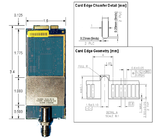
Figure 1. NX915 Transceiver Module
(Mini PCI-Express Card Edge for Data/Power/& I/O and J300 Antenna)
NOTE: Some features may not be available on all units, based on the options purchased, or regulatory constraints in
the country of operation.
2.0 INSTALLATION
The transceiver is designed for installation in existing electronic equipment. The I/O and power connections are made
through the Mini PCI-Express card edge and it mounts to the host heatsink assembly using two #4 screws inside the
RF can area. The required heatsink contact area on the bottom surface of the PCB has the solder mask removed for
proper heat transfer.
Only one cable connection is required to the radio for the J300 Antenna connector. Note that the module does have
four optionally populated status LEDs (CR100, 101, 200, and 201) that indicate operating mode details. These LEDs
provide important information that is useful during startup and optimization of the radio link.
Antennas used with the radio can be either a Yagi directional type (often used at remote sites) or an omni-directional
type used for short range applications or at Master stations. Contact your sales representative for information on
available antennas.
Follow these steps to install the transceiver module:
1. Power down the Host assembly the module is being installed in to.
2. Mate the MiniPCIe card edge of the module into the socket on the Host assembly.
3. Secure the module to the heatsink surface using two #4 screws through the mounting holes in the corners of
the RF can area on the radio’s PC board.
3. Install the RF shield over the transceiver section.
4. Select and install an appropriate antenna and feedline for your system coverage requirements.
5. Connect the antenna coaxial lead to J300 on the module. It accepts a Type-TNC male coaxial connector.
- For antenna gains higher than 6dBi, the system has been approved only with the following types:
a. MDS PN: 97-3194A23 (Manuf. PN: Z2402 from PCTEL, Inc.), 7dBd (9.15 dBi), Omnidirectional
b. MDS PN: 97-3194A14E (Manuf. PN: Z2342 from PCTEL, Inc.), 10dBd (12.15 dBi) Yagi
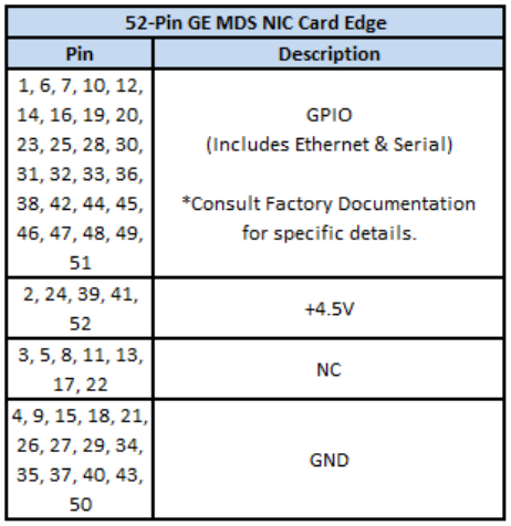
6. Host Power Supply Requirement: The input power applied to the unit must be 4.5 Vdc (-/+0.05 V).
See Table 1 for power supply interface connections.
Table 1. NX915 Power Supply Connections
7. Set the radio’s basic configuration with a PC terminal through the Host system. The three essential settings for
all transceivers are (See Section 3 for commands):
•Frequency
•Power
•Modem
8. In a normally operating system, you will see the CR100 POWER LED turn on at start-up.
9. Optimize the installation by checking:
•Antenna aiming and SWR check
•Optimal baud rate setting
•Radio interference checks
3.0 RADIO PROGRAMMING
There are no manual adjustments on the radio. All programming and control is performed through a PC connected to
the Host platform that interfaces with the radio’s J200 MiniPCIe card edge connector.
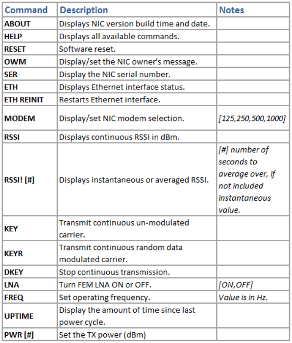
3.1 User Commands
The following tables provide descriptions of the various user commands for the transceiver.
Table 2. NX915 User Commands
4.0 DC INPUT REQUIREMENTS
4.1 Power Consumption Ratings
The module has the following nominal power consumption ratings when operated at the required input voltage of 4.5
Vdc (-0.05/+0.05 V tolerance) at the power connections:
Active Receive Mode: 130mA, Transmit Mode (Worst Case Load): 1.3 Amperes
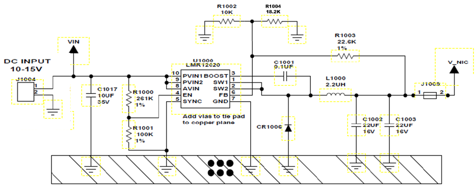
4.5 VDC Power Regulation must be met by OEM to satisfy LMA conditions:
OEM Integrator should consult with Product Support for individual circuit implementations. At minimum, OEM
Integrators must regulate the DC voltage applied to the NX915 module at +4.5 Vdc (V_NIC), with a tolerance of -
0.05/+0.05 Vdc. This can be achieved using a voltage regulator similar to the Texas Instruments LMR12020, which is
a precision DC regulator. The external +4.5 VDC input is connected via pins 2, 24, 39, 41, and 52 of the 52 pin
MiniPCIe card edge connector. The transmitter uses a closed-loop power detection circuit that ensures the peak RF
power will never exceed +30dBm.
The input voltage range of the LMR12020 device in this configuration is 10V to 15V. Using switched-mode power-
conversion technology, the LMR12020 can step down to voltages as low as 1.13V from a 10V input bus, with typically
less than 1 W of power dissipation. The output voltage must be set to a voltage of 4.5V, using an external trim
resistor. Operating features of the TI device include cycle-by-cycle current limiting, under-voltage lockout (UVLO),
on/off inhibit, output overcurrent protection, and over-temperature protection.
For example purposes, a circuit employing this method of regulation is shown below in schematic form.

5.0 REGULATORY AND RF OUTPUT POWER REQUIREMENTS
5.1 Technical Assistance
Factory technical assistance is available by contacting GE MDS during business hours (8:30 AM to 6:00 PM Eastern
Time). Use one of the following means to contact the factory:
Telephone: (585) 241-5510 FAX: (585) 242-8369 E-mail: gemds.techsupport@ge.com Web: www.gemds.com
5.2 Regulatory Information
Federal Communication Commission Sec 15.105 Interference Statement
This equipment has been tested and found to comply with the limits for a Class B digital device, pursuant to Part 15
of the FCC Rules. These limits are designed to provide reasonable protection against harmful interference in a
residential installation. This equipment generates uses and can radiate radio frequency energy and, if not installed
and used in accordance with the instructions, may cause harmful interference to radio communications. However,
there is no guarantee that interference will not occur in a particular installation. If this equipment does cause harmful
interference to radio or television reception, which can be determined by turning the equipment off and on, the user is
encouraged to try to correct the interference by one of the following measures:
- Reorient or relocate the receiving antenna.
- Increase the separation between the equipment and receiver.
- Connect the equipment into an outlet on a circuit different from that to which the receiver is connected.
- Consult the dealer or an experienced radio/TV technician for help.
FCC Part 15 and Industry Canada RSS Notices
This device complies with Part 15 of the FCC Rules and Industry Canada license-exempt RSS standard(s). Operation
is subject to the following two conditions: (1) this device may not cause interference, and (2) this device must accept
any interference that may cause undesired operation of the device.
Warning: Changes or modifications not expressly approved by the manufacturer could void the user’s authority to
operate the equipment.
a) Under Industry Canada regulations, this radio transmitter may only operate using an antenna of a type and
maximum (or lesser) gain approved for the transmitter by Industry Canada. To reduce potential radio interference to
other users, the antenna type and its gain should be so chosen that the equivalent isotropically radiated power
(e.i.r.p.) is not more than that necessary for successful communication.
b) The radio transmitter described herein (IC ID: 101D-NX915) has been approved by Industry Canada to operate
with the antenna types listed below with the maximum permissible gain and required antenna impedance for each
antenna type indicated. Antenna types not included in this list, having a gain greater than the maximum gain indicated
for that type, are strictly prohibited for use with this device.
Cet appareil est conforme à la Partie 15 des règlements de la FCC et Industrie Canada exempts de licence standard
RSS (s). Son utilisation est soumise à deux conditions: (1) ce dispositif ne peut causer des interférences, (2) cet
appareil doit accepter toute interférence pouvant causer un mauvais fonctionnement du dispositif.
a) En vertu des règlements d'Industrie Canada, cet émetteur radio ne peut fonctionner avec une antenne d'un type et
un maximum (ou moins) approuvés pour gagner de l'émetteur par Industrie Canada. Pour réduire le risque
d'interférence aux autres utilisateurs, le type d'antenne et son gain doivent être choisies de façon que la puissance
isotrope rayonnée équivalente (PIRE) ne dépasse pas ce qui est nécessaire pour une communication réussie.
b) L'émetteur radio décrit ci-après (IC ID: 101D-NX915) a été approuvé par Industrie Canada pour fonctionner avec
les types d'antennes énumérées ci-dessous avec le gain maximal admissible et nécessaire antenne d'impédance

pour chaque type d'antenne indiqué. Types d'antennes ne figurent pas dans cette liste, ayant un gain supérieur au
gain maximum indiqué pour ce type, sont strictement interdites pour une utilisation avec cet appareil.
FCC Limited Modular Approval Notice
This device is offered as an FCC Part 15 Unlicensed Limited Modular Transmitter (LMA). The transmitter module is
approved for use only with specific antenna, cable and output power configurations that have been tested and
approved for use when installed in devices approved by third-party OEMs, or produced by the Grantee (GE MDS).
Modifications to the radio, the antenna system, or power output, that have not been explicitly specified by the
manufacturer are not permitted, and may render the radio non-compliant with applicable regulatory authorities.
When this module is placed inside an enclosure, a durable label must be affixed to the outside of the final host device
and shall be labeled with “Contains FCC ID: E5MDS-NX915, Contains IC: 101D-NX915” indicating the module’s
FCC ID & IC Numbers.
Note: A host product is required to comply with all applicable FCC & Industry Canada equipment authorizations
regulations and/or requirements and equipment functions not associated with the transmitter module portion. For
example requirements for any co-location of additional transmitter with the module and/or at the minimum compliance
with FCC part 15B & IC ICES-003; Digital device are the sole responsibility of the OEM integrators for the final host
device.
RF Exposure Warnings
The antenna(s) to be used with this module must be installed with consideration to the guidelines for RF exposure
risk to all nearby personnel, and must not be co-located or operating in conjunction with any other antenna or
transmitter.
Professional installation required. The radio equipment described in this guide emits radio frequency energy.
Although the power level is low, the concentrated energy from a directional antenna may pose a health hazard. Do
not allow people to come closer than 23 cm (9 inches) to the antenna when the transmitter is operating in indoor or
outdoor environments. In mobile applications (vehicle mounted) the above separation distance must be maintained at
all times. More information on RF exposure is available online at: www.fcc.gov/oet/info/documents/bulletins
L'énergie concentrée en provenance d'une antenne directionnelle peut présenter un danger pour la santé. Ne pas
permettre aux gens de s'approcher à moins de 23 cm à l'avant de l'antenne lorsque l'émetteur est en opération. On
doit augmenter la distance proportionnellement si on utilise des antennes ayant un gain plus élevé . Ce guide est
destiné à être utilisé par un installateur professionnel. Plus d'informations sur l'exposition aux rayons RF peut être
consulté en ligne à l'adresse suivante:
www.fcc.gov/oet/info/documents/bulletins RF Exposure Notices

5.3 RF Output Settings
Consult Table 3 for the maximum applicable power settings. The NX915 is a multi-modem system offering both
Frequency Hopping Spread Spectrum and DTS transceiver modes in the license-free 902-928 MHz band. It
therefore has specific output power limits for each modem dependent on your installation. Since RF cable lengths
and cable types may vary from one installation to another it is critical to comply with the following:
The EIRP shall be calculated based on the transmitter antenna gain (GdBi), cable loss (CLdB) and Peak output
power at the antenna terminal (PdBm). Calculated EIRP = PdBm + GdBi - CLdB
Never exceed the modem specific EIRP values listed in Table 3 for any given system loss.
Table 3. NX915 Max Power Settings
Max Power Settings for FHSS modes
Antenna Gain
(Antenna Gain in dBi1) Modem
Selection
Peak Output Power
at Antenna Terminal
(dBm)
Cable Loss
(System Attenuation)
EIRP2
(dBm)
6 (or less) Omni or Yagi 125 29.99 0.86dB 35.13
9.15 Omni Directional Antenna 125 29.99 3.86dB 35.28
12.15 Yagi Antenna 125 29.99 6.86dB 35.28
6 (or less) Omni or Yagi 250 29.99 0.86dB 35.13
9.15 Omni Directional Antenna 250 29.99 3.86dB 35.28
12.15 Yagi Antenna 250 29.99 6.86dB 35.28
Max Power Settings for DTS modes
Antenna Gain
(Antenna Gain in dBi1) Modem
Selection
Peak Output Power
at Antenna Terminal
(dBm)
Cable Loss
(System Attenuation) EIRP2
(dBm)
6 (or less) Omni or Yagi 500 27.93 0.86dB 33.07
9.15 Omni Directional Antenna 500 27.93 1.86dB 35.22
12.15 Yagi Antenna 500 27.93 4.86dB 35.22
6 (or less) Omni or Yagi 1000 28.80 0.86dB 33.94
9.15 Omni Directional Antenna 1000 28.80 2.86dB 35.09
12.15 Yagi Antenna 1000 28.80 5.86dB 35.09
6 (or less) Omni or Yagi 1000W 29.62 0.86dB 34.76
9.15 Omni Directional Antenna 1000W 29.62 2.86dB 35.91
12.15 Yagi Antenna 1000W 29.62 5.86dB 35.91
1. Most antenna manufacturers rate antenna gain in dBd. To convert to dBi, add 2.15 dB.
2. Feedline loss varies by cable type and length. Installation specific compensation is required.