GE MDS DS-SD4-1 Data Transceiver User Manual 4670D SD x710 Reference
GE MDS LLC Data Transceiver 4670D SD x710 Reference
GE MDS >
Manual

Installation and Operation Guide
Reference Manual
MDS 05-4670A01, Rev. E
MARCH 2015
Covering Units Operating in x710 Mode
with Firmware Version 4.x
MDS SD Series
Secure, Long Range Data Communications
Need Quick-Start instructions for this product? Please refer to publication 05-4669A01.
All GE MDS user guides are available online at www.gemds.com

MDS 05-4670A01, Rev. E SD Series Reference Manual (x710 Mode) i
TABLE OF CONTENTS
RF Safety Notice (English and French) .......................................................................................... iv
FCC Part 15 Notice......................................................................................................................... iv
Industry Canada Notice .................................................................................................................. iv
1.0 INTRODUCTION .................................................................................................................. 1
1.1 Conventions Used in This Manual .................................................................................................1
1.2 Electronic Manuals ........................................................................................................................ 2
2.0 PRODUCT DESCRIPTION................................................................................................... 3
2.1 Front Panel Connectors and Indicators ......................................................................................... 3
2.2 Key Product Features ....................................................................................................................4
2.3 Model Offerings ............................................................................................................................. 4
2.4 Operating Modes and Applicable Manuals ....................................................................................5
2.5 Accessories and Spares ................................................................................................................ 6
3.0 APPLICATIONS .................................................................................................................... 6
Point-to-Multipoint, Multiple Address Systems (MAS) .....................................................................6
Point-to-Point System ......................................................................................................................7
Continuously-Keyed versus Switched-Carrier Operation.................................................................8
Single-Frequency (Simplex) Operation............................................................................................ 8
4.0 INSTALLATION PLANNING ................................................................................................. 8
4.1 Typical Installation ......................................................................................................................... 8
4.2 Mounting Options ..........................................................................................................................9
Optional DIN Rail Mounting ...........................................................................................................10
4.3 Antennas and Feedlines .............................................................................................................. 11
Feedlines ....................................................................................................................................... 11
4.4 DC Power Connection .................................................................................................................12
4.5 Grounding Considerations ...........................................................................................................13
4.6 COM1 (Management) Connections .............................................................................................13
COM1 in Analog Operation............................................................................................................14
4.7 COM2 (Data) Connections ..........................................................................................................15
4.8 Ethernet Interface (RJ-45) ...........................................................................................................17
5.0 STEP-BY-STEP INSTALLATION ........................................................................................ 18
5.1 Initial Startup & Checkout ............................................................................................................19
5.2 Initial Software Configuration .......................................................................................................19
Serial vs. Telnet Access, and the Device Manager........................................................................20
Connecting a PC & Setting Basic Parameters...............................................................................20
6.0 TRANSCEIVER MANAGEMENT........................................................................................ 21
6.1 Software Commands ...................................................................................................................21

MDS 05-4670A01, Rev. E SD Series Reference Manual (x710 Mode) ii
Entering Commands ......................................................................................................................21
6.2 Detailed Command Descriptions .................................................................................................24
AK ..................................................................................................................................................25
ALARM...........................................................................................................................................25
AMASK [0000 0000–FFFF FFFF]..................................................................................................25
ASENSE [HI, LO] ...........................................................................................................................25
AUDIO [ON, OFF] ..........................................................................................................................26
BAUD [xxxxx abc] ..........................................................................................................................26
BIN [DATA, CLEAR] .......................................................................................................................26
BOOT.............................................................................................................................................26
BUFF [ON, OFF] ............................................................................................................................26
CKEY [ON–OFF]............................................................................................................................27
CTS [0–255]...................................................................................................................................27
CTSHOLD [0–60000].....................................................................................................................27
DATAKEY [ON, OFF] .....................................................................................................................28
DEV................................................................................................................................................28
DEVICE [DCE, CTS KEY]..............................................................................................................28
DKEY .............................................................................................................................................28
DLINK [ON/OFF/xxxx]....................................................................................................................28
DTYPE [NODE/ROOT] ..................................................................................................................29
DUMP ............................................................................................................................................29
EMP [ON/OFF]...............................................................................................................................29
ETHADDR......................................................................................................................................29
FORCEALARM [ON or OFF] .........................................................................................................29
FORCEDCD [ON or OFF]..............................................................................................................29
HELP..............................................................................................................................................29
INIT ................................................................................................................................................ 30
INIT [SDx] ......................................................................................................................................30
INIT [P-20]...................................................................................................................................... 30
IPCONFIG...................................................................................................................................... 31
KEY................................................................................................................................................31
MENU ............................................................................................................................................ 31
MODEL1 ........................................................................................................................................31
MODEL2 ........................................................................................................................................31
MODEM [xxxx] ...............................................................................................................................31
OWM [XXX...].................................................................................................................................33
OWN [XXX...] .................................................................................................................................33
PORT [RS232, RS485] ..................................................................................................................34
PTT [0–255] ...................................................................................................................................34
PTTSIG [OFF, LOW, HI].................................................................................................................34
PWR [20–37]..................................................................................................................................34
RESTORECONFIG........................................................................................................................34
RESTOREDEFAULTS ...................................................................................................................34
RMODE [X710, TRANSPARENT, PACKET, CMAC, HELP] ..........................................................34
RSSI...............................................................................................................................................34
RTSKEY [ON, OFF] .......................................................................................................................35
RTU [ON/OFF/0-80] .......................................................................................................................35
RX [xxx.xxxx] .................................................................................................................................35
RXATTN [ON or OFF] .................................................................................................................... 35
RXLEVEL [–20 to 0].......................................................................................................................35
RXTOL [NORMAL or CUSTOM] ....................................................................................................36

MDS 05-4670A01, Rev. E SD Series Reference Manual (x710 Mode) iii
RXTOT [NONE, 1-1440] ................................................................................................................36
SAVECONFIG................................................................................................................................36
SCD [0-255] ...................................................................................................................................36
SER................................................................................................................................................36
SHOW [DC, PWR] .........................................................................................................................36
SNR ............................................................................................................................................... 36
SPECTRUM [xxx.xx]......................................................................................................................37
SQUELCH [AUTO, BYPASSED]....................................................................................................37
SREV .............................................................................................................................................37
STAT ..............................................................................................................................................38
SWC [ON, OFF] .............................................................................................................................38
TFTP .............................................................................................................................................. 38
TEMP ............................................................................................................................................. 38
TOT [1-255, ON, OFF] ...................................................................................................................39
TX [xxx.xxxx].................................................................................................................................. 39
TXLEVEL [–20 to 0, AUTO] ...........................................................................................................39
UNIT [10000...65000].....................................................................................................................39
UPTIME .........................................................................................................................................39
VERSION.......................................................................................................................................39
7.0 TROUBLESHOOTING........................................................................................................ 40
7.1 LED Indicators .............................................................................................................................40
7.2 Event Codes ................................................................................................................................40
Checking for Alarms—STAT command..........................................................................................40
Major Alarms vs. Minor Alarms ......................................................................................................41
Event Code Definitions ..................................................................................................................41
8.0 TECHNICAL REFERENCE ................................................................................................ 43
8.1 Technical Specifications .............................................................................................................43
8.2 Performing Network-Wide Remote Diagnostics ..........................................................................45
8.3 User-Programmable I/O Functions - Pending .............................................................................46
8.4 Analog Operation of the Transceiver ........................................................................................... 46
Physical Interface...........................................................................................................................47
Operational Characteristics............................................................................................................47
8.5 Upgrading the Radio’s Firmware .................................................................................................48
Web Method...................................................................................................................................49
TFTP Method .................................................................................................................................50
Serial Transfer Method...................................................................................................................52
Error Messages During File Transfers ...........................................................................................54
8.6 dBm-Watts-Volts Conversion Chart .............................................................................................55
9.0 GLOSSARY OF TERMS..................................................................................................... 56
Copyright and Trademark
This manual and all software described herein is protected by Copyright: 2012 GE MDS, LLC. All
rights reserved. GE MDS, LLC reserves its right to correct any errors and omissions in this publi-
cation. Modbus
®
is a registered trademark of Schneider Electric Corporation. All other trademarks
and product names are the property of their respective owners.
iv SD Series Reference Manual (x710 Mode) MDS 05-4670A01, Rev. E
RF Safety Notice
(English and French)
Concentrated energy from a directional antenna may pose a health hazard to
humans. Do not allow people to come closer to the antenna than the distances
listed in the table below when the transmitter is operating. More information on
RF exposure can be found online at the following web site:
www.fcc.gov/oet/info/documents/bulletins.
Concentré d'énergie à partir d'une antenne directionnelle peut poser un risque
pour la santé humaine. Ne pas permettre aux gens de se rapprocher de l'antenne
que les distances indiquées dans le tableau ci-dessous lorsque l'émetteur est en
marche. Plus d'informations sur l'exposition aux RF peut être trouvé en ligne à
l'adresse suivante: www.fcc.gov/oet/info/documents et bulletins.
FCC Part 15 Notice
Operation is subject to the following two conditions: (1) this device may not cause harmful inter-
ference, and (2) this device must accept any interference received, including interference that may
cause undesired operation. Any unauthorized modification or changes to this device without the
express approval of the manufacturer may void the user’s authority to operate this device. Further-
more, this device is intended to be used only when installed in accordance with the instructions out-
lined in this manual. Failure to comply with these instructions may void the user’s authority to
operate this device.
Industry Canada Notice
This Class A digital apparatus complies with Canadian ICES-003.
Cet appareil numérique de la classe A est conforme à la norme NMB-003 du Canada.
Antenna Gain vs. Minimum RF Safety Distance
Antenna Gain
0–5 dBi 5–10 dBi 10–16.5 dBi
Safety Distance (SD4) 0.93 meter 1.66 meters 3.51 meters
Safety Distance (SD9) 0.72 meter 1.28 meters 2.71 meters
Safety Distance (SD1)
For SD1, maintain an RF safety distance of
2.02 meters for a 7 dBd (9.15 dBi) antenna.
Use of higher gain antennas means
increasing the distance accordingly.
Safety Distance (SD2)
For SD2, maintain an RF safety distance of
1.89 meters for a 7 dBd (9.15 dBi) antenna.
Use of higher gain antennas means
increasing the distance accordingly.
Safety Distance
(Other SD models):
Consult factory prior to operation.
RF Exposure
l'exposition aux RF

MDS 05-4670A01, Rev. E SD Series Reference Manual (x710 Mode) v
Servicing Precautions
When servicing energized equipment, be sure to wear appropriate Personal Protective Equipment
(PPE). During internal service, situations could arise where objects accidentally contact or short
circuit components and the appropriate PPE would alleviate or decrease the severity of potential
injury. When servicing radios, all workplace regulations and other applicable standards for live
electrical work should be followed to ensure personal safety.
Manual Revision and Accuracy
This manual was prepared to cover a specific version of firmware code. Accordingly, some screens
and features may differ from the actual unit you are working with. While every reasonable effort
has been made to ensure the accuracy of this publication, product improvements may also result in
minor differences between the manual and the product shipped to you. If you have additional ques-
tions or need an exact specification for a product, please contact GE MDS using the information at
the back of this guide. In addition, manual updates can be found on our web site at
www.gemds.com
Environmental Information
The manufacture of this equipment has required the extraction and use of natural resources.
Improper disposal may contaminate the environment and present a health risk due to hazardous
substances contained within. To avoid dissemination of these substances into our environment, and
to limit the demand on natural resources, we encourage you to use the appropriate recycling sys-
tems for disposal. These systems will reuse or recycle most of the materials found in this equipment
in a sound way. Please contact GE MDS or your supplier for more information on the proper dis-
posal of this equipment.
Battery Disposal
—This product may contain a battery. Batteries must be disposed of properly, and
may not be disposed of as unsorted municipal waste in the European Union. See the product doc-
umentation for specific battery information. Batteries are marked with a symbol, which may
include lettering to indicate cadmium (Cd), lead (Pb), or mercury (Hg). For proper recycling return
the battery to your supplier or to a designated collection point. For more information see:
www.weeerohsinfo.com.
Product Test Data Sheets
Test Data Sheets showing the original factory test results for this unit are available upon request
from the GE MDS Quality Leader. Contact the factory using the information at the back of this
manual. Serial numbers must be provided for each product where a Test Data Sheet is required.
CSA/us Notice
This product is approved for use in Class 1, Division 2, Groups A, B, C & D Hazardous Locations.
Such locations are defined in Article 500 of the National Fire Protection Association (NFPA) pub-
lication NFPA 70, otherwise known as the National Electrical Code. The transceiver has been rec-
ognized for use in these hazardous locations by the Canadian Standards Association (CSA) which
also issues the US mark of approval (CSA/
US
). The CSA Certification is in accordance with CSA
STD C22.2 No. 213-M1987.

vi SD Series Reference Manual (x710 Mode) MDS 05-4670A01, Rev. E
CSA Conditions of Approval: The transceiver is not acceptable as a stand-alone unit for use in the
hazardous locations described above. It must either be mounted within another piece of equipment
which is certified for hazardous locations, or installed within guidelines, or conditions of approval,
as set forth by the approving agencies. These conditions of approval are as follows: The transceiver
must be mounted within a separate enclosure which is suitable for the intended application.The
antenna feedline, DC power cable and interface cable must be routed through conduit in accor-
dance with the National Electrical Code. Installation, operation and maintenance of the transceiver
should be in accordance with the transceiver's installation manual, and the National Electrical
Code. Tampering or replacement with non-factory components may adversely affect the safe use
of the transceiver in hazardous locations, and may void the approval. A power connector with
screw-type retaining screws as supplied by GE MDS must be used.
Do not disconnect equipment unless power has been switched off or the area is known to
be non-hazardous. Refer to Articles 500 through 502 of the National Electrical Code
(NFPA 70) for further information on hazardous locations and approved Division 2 wiring
methods.
BSD License Information
The SD Series products contain source code originally released as part of “WPA Supplicant” which
is copyrighted as indicated below and is redistributed under the terms of the BSD license:
WPA Supplicant
Copyright (c) 2003-2010, Jouni Malinen <j@w1.fi> and contributors
All Rights Reserved.
BSD License
-------
Redistribution and use in source and binary forms, with or without modification, are permitted pro-
vided that the following conditions are met:
1. Redistributions of source code must retain the above copyright notice, this list of conditions and
the following disclaimer.
2. Redistributions in binary form must reproduce the above copyright notice, this list of conditions
and the following disclaimer in the documentation and/or other materials provided with the distri-
bution.
3. Neither the name(s) of the above-listed copyright holder(s) nor the names of its contributors may
be used to endorse or promote products derived from this software without specific prior written
permission.
THIS SOFTWARE IS PROVIDED BY THE COPYRIGHT HOLDERS AND CONTRIBUTORS
“AS IS” AND ANY EXPRESS OR IMPLIED WARRANTIES, INCLUDING, BUT NOT LIM-
ITED TO, THE IMPLIED WARRANTIES OF MERCHANTABILITY AND FITNESS FOR A
PARTICULAR PURPOSE ARE DISCLAIMED. IN NO EVENT SHALL THE COPYRIGHT
OWNER OR CONTRIBUTORS BE LIABLE FOR ANY DIRECT, INDIRECT, INCIDENTAL,
SPECIAL, EXEMPLARY, OR CONSEQUENTIAL DAMAGES (INCLUDING, BUT NOT
LIMITED TO, PROCUREMENT OF SUBSTITUTE GOODS OR SERVICES; LOSS OF USE,
EXPLOSION
HAZARD!
MDS 05-4670A01, Rev. E SD Series Reference Manual (x710 Mode) vii
DATA, OR PROFITS; OR BUSINESS INTERRUPTION) HOWEVER CAUSED AND ON
ANY THEORY OF LIABILITY, WHETHER IN CONTRACT, STRICT LIABILITY, OR TORT
(INCLUDING NEGLIGENCE OR OTHERWISE) ARISING IN ANY WAY OUT OF THE USE
OF THIS SOFTWARE, EVEN IF ADVISED OF THE POSSIBILITY OF SUCH DAMAGE.

viii SD Series Reference Manual (x710 Mode) MDS 05-4670A01, Rev. E
MDS 05-4670A01, Rev. E SD Series Reference Manual (x710 Mode) 1
1.0 INTRODUCTION
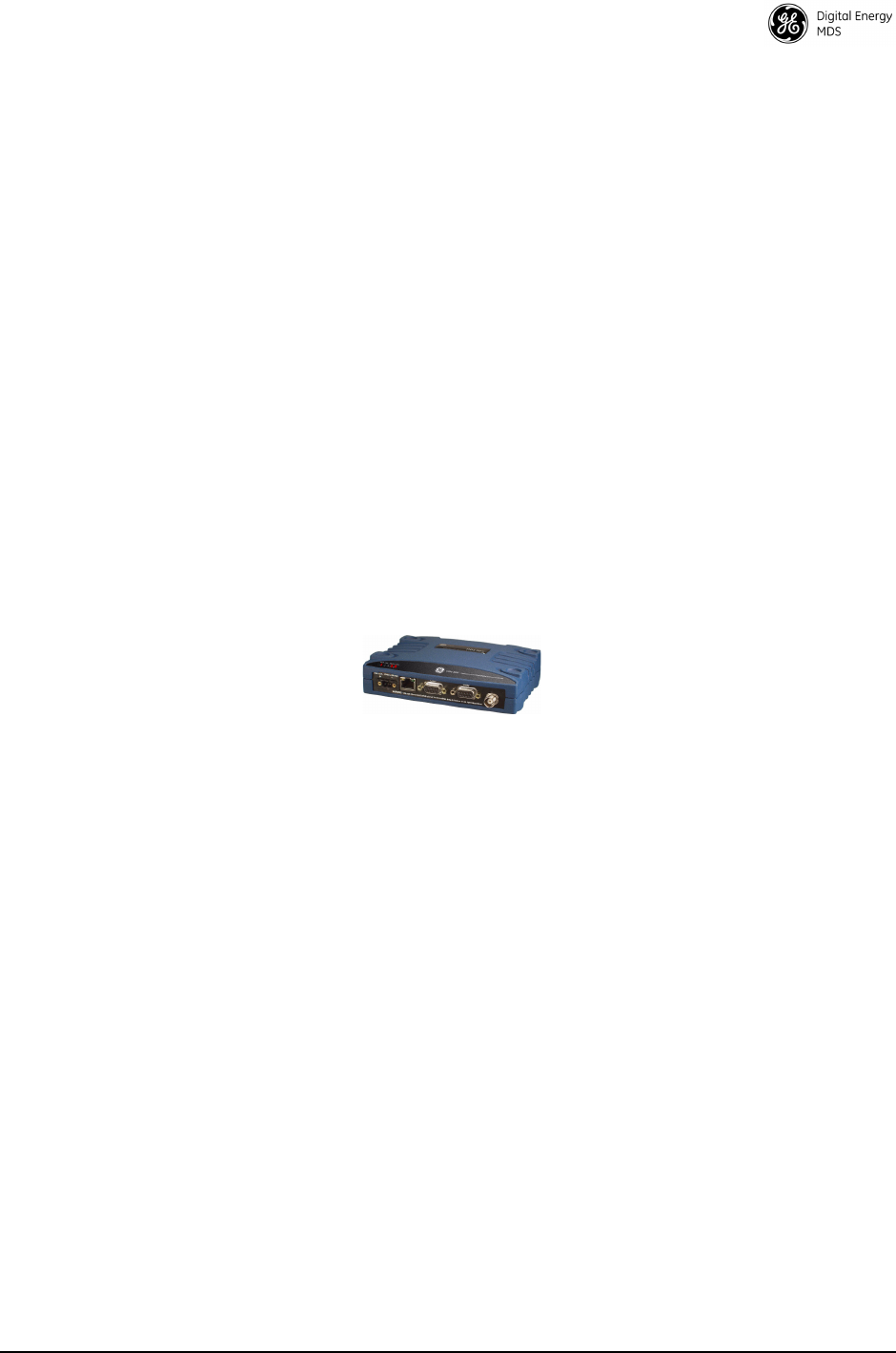
This Reference Manual is one of two books provided for users of the
MDS SD Series Transceiver (Figure 1) operating in x710 Mode. It con-
tains an overview of common applications, installation planning data,
technical specifications, troubleshooting, and a listing of software com-
mands. This manual should be available to technical personnel who per-
form network design, configuration, and troubleshooting of the
equipment.
A companion Instruction Sheet is also available (Part no. 05-4669A01).
The scope of the Instruction Sheet is limited to installing the transceiver
and placing it in service for the first time.
Invisible place holder
Figure 1. MDS SD Series Transceiver
1.1 Conventions Used in This Manual
Software Notations
This product is designed for software control using a connected PC. To
indicate the names of software commands, keyboard entries, or other
information shown on a PC screen, a distinctive, bolded font is used as
follows:
Bolded font example (used for software commands and keyboard entries)
Model Number
Notations
The term “SD” or “SD Series” is used in this manual to denote all
models in the SD product line. Specific model numbers such as “MDS
SD2” (216-235 MHz) “MDS SD4” (350-512 MHz) and MDS SD9
(928-960 MHz) are used only when necessary to reference model-spe-
cific features. This manual applies to all SD radios operating in x710
Mode.
Authorization
Features
Some features of the radio are dependent on purchased options and
applicable regulatory constraints. A “key” icon is shown near the
heading of these features in this manual. If your radio is not currently
authorized for a needed feature, contact your factory representative for
information on obtaining a new authorization code/key.

2 SD Series Reference Manual (x710 Mode) MDS 05-4670A01, Rev. E
1.2 Electronic Manuals
All SD Series manuals are available in printed or electronic form.
Download electronic manuals from our web site at www.gemds.com.
The web site also contains links to Application Bulletins and other
product information.

MDS 05-4670A01, Rev. E SD Series Reference Manual (x710 Mode) 3
2.0 PRODUCT DESCRIPTION
The SD Transceiver is a software-configurable, industrial radio for use
in licensed data acquisition networks. It can be interfaced with a variety
of data control equipment including remote terminal units (RTUs), pro-
grammable logic controllers (PLCs), flow computers, and similar
devices. Data interface connections can be made for both serial
(RS-232/RS-485) and local Ethernet protocols.
The radio’s x710 Mode is designed primarily for use in serial MDS x710
radio networks where a central station communicates with each remote,
one at a time, to convey data and control signals. For models operating
in this mode, the radio offers direct, drop-in compatibility with existing,
older x710 networks while providing additional functionality not found
in MDS x710 radios. An SD Transceiver in x710 mode looks like an
x710 with respect to over-the-air transmission and all serial user inter-
face commands (plus some new SD-specific commands).
The transceiver employs digital signal processing (DSP) technology and
a fully digital transmit and receive IF chain to provide robust communi-
cations even under adverse conditions. Digital signal processing also
helps eliminate the effects of component variations or temperature
swings, resulting in an optimized performance.
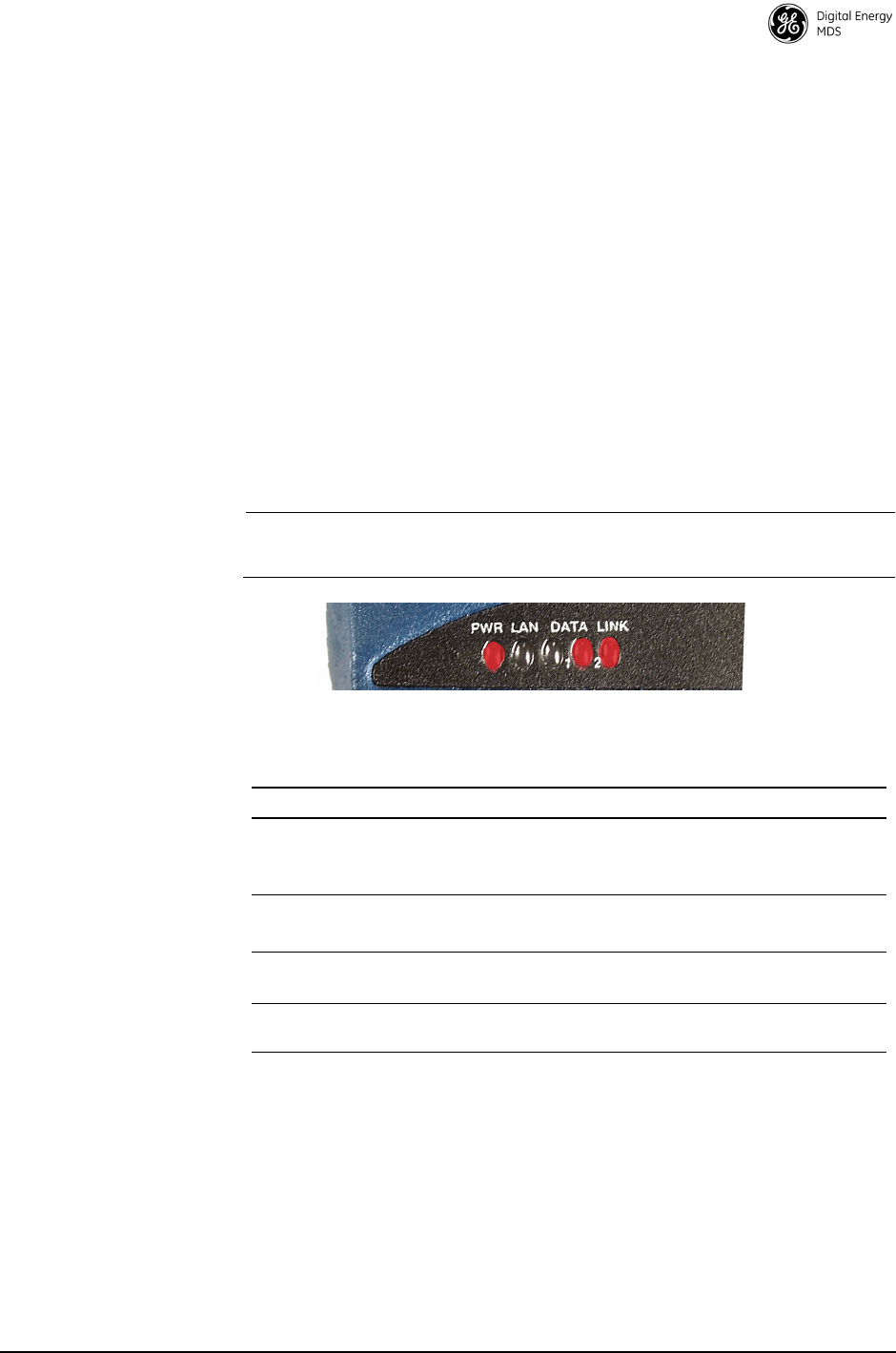
2.1 Front Panel Connectors and Indicators
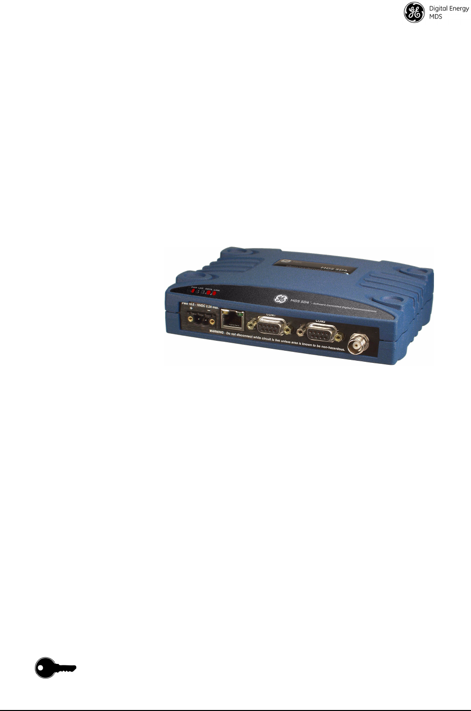
Figure 2 shows the transceiver’s front panel connectors and indicators.
These items are referenced in various locations in this manual. The
transceiver’s LED functions are described in Table 10 on Page 19.
Invisible place holder
Figure 2. Front Panel Connectors & Indicators
ANTENNA
CONNECTOR (TNC)
SERIAL DATA
CONNECTORS (DB-9)
DC INPUT
POWER
LED INDICATOR
PANEL
ETHERNET
CONNECTOR (RJ-45)
COM1 used for radio management

4 SD Series Reference Manual (x710 Mode) MDS 05-4670A01, Rev. E
2.2 Key Product Features
The transceiver is designed to meet the demanding needs of today’s
industrial wireless networks in a compact, rugged package. It offers an
array of features in one hardware platform:
• Ethernet & serial interfaces—ideal for migration to IP networks
• Dual serial functionality (RS-232 and RS-485)
• Software configurable using the built-in interface, and Web man-
agement—no manual controls or adjustments. Supports Serial,
Telnet, or web-based management.
• Over-the-air reprogramming—no unnecessary trips to radio sites
• Licensed 5-watt design, maximizes communications range with
low interference risk from other users
• Configurable as a Remote or a Master unit
• Low power “sleep mode”—ideal for battery-powered solar sites
• Drop-in compatibility with MDS x710 radios (x710 mode)
• Supports a wide variety of modem speeds and bandwidths for
regulatory compliance in virtually all regions of the world
NOTE:
Some features might not be available on all units, depending on the
options purchased and regulatory constraints for the region in which
the radio will operate
.
2.3 Model Offerings
The radio is available in three model configurations:
•Ethernet—All SD features and functionality
•Standard—All features except Ethernet functionality
•x710—Direct, drop-in compatibility for networks using a mix of
SD and older MDS x710 radios. The Ethernet port is available for
radio management in x710 mode, but not for payload.
Model Number
Codes
The unit’s complete model number is printed on the bottom label. Addi-
tional unit details are available through the
MODEL1
and
MODEL2
com-
mands, described later in this manual.
MDS 05-4670A01, Rev. E SD Series Reference Manual (x710 Mode) 5
2.4 Operating Modes and Applicable Manuals
SD Transceivers can be configured to operate in any one of three modes:
•x710 Mode—This mode provides direct, drop-in compatibility
with MDS x710 (4710 or 9710) transceivers, and uses the same
core command set as these radios. It is ideal for use in systems
containing a mix of newer SD radios and legacy MDS x710 units.
This manual covers x710 Mode radios.
•Packet Mode (including Packet w/MAC)—Payload data from
the radio’s serial or Ethernet ports is assembled into packets and
transmitted over the air. Packet mode supports Ethernet Bridging,
AES 128-bit encryption, and multihost operation. This mode is
ideal for networks containing all SD radios. This manual does not
cover Packet Mode radios. See below for applicable manuals.
•Transparent Mode—This mode is over-the-air compatible with
MDS x710 transceivers, while supporting payload data on the
Ethernet interface. This mode is ideal for mixed networks con-
taining SD and MDS x710 radios. It allows currently deployed
x710 networks to add the ability to support Ethernet data. This
manual does not cover Transparent Mode radios. See below for
applicable manuals.
For Packet Mode and Transparent Mode operation, refer instead to the
following manuals for instructions:
•Start-Up Guide—Part No. 05-4847A01
•Reference Manual—Part No. 05-4846A01
Invisible place holder
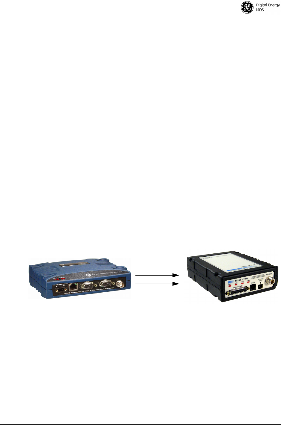
Figure 3. SD Transceivers offer compatibility with older MDS x710
Transceivers (right), and may be used for replacement or
interoperability in these networks. A retrofit kit is available for
connector conversion (see Table 1).

6 SD Series Reference Manual (x710 Mode) MDS 05-4670A01, Rev. E
2.5 Accessories and Spares
Table 1 lists common accessories and spare items for the transceiver.
GE MDS also offers an Accessories Selection Guide listing additional
items that can be used with the product. Contact your factory represen-
tative or visit
www.gemds.com
to obtain a copy of the guide.
3.0 APPLICATIONS
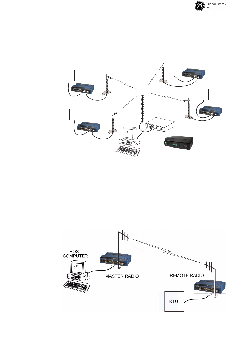
Point-to-Multipoint, Multiple Address Systems (MAS)
This is the most common application of the transceiver. It consists of a
central master station and several associated remote units as shown in
Figure 4. An MAS network provides communication between a central
host computer and remote terminal units (RTUs) or other data collection
devices. The operation of the radio system is transparent to the computer
equipment.
Often, such a system is used to convey telemetry data to and from
widely separated remote radios. Typical applications include automatic,
remote monitoring of gas wells, water tank levels, electric power distri-
bution systems, and similar control and measurement functions.
The radio system can replace a network of remote monitors currently
linked to a central location using leased telephone lines or other hard-
wired means. At the central office of such a system, there is usually a
dedicated computer and some means of switching between individual
Table 1. Accessories & Ancillary Items
Accessory Description Part Number
Retrofit Kit, Digital Contains adapters and connectors
needed to facilitate the replacement
of an existing MDS x710A/C/M
digital transceiver.
03-4696A01
Retrofit Kit, Analog Contains adapters and connectors
needed to facilitate the replacement
of an existing MDS x710A/C/M
analog transceiver.
03-4697A01
DC Power Plug,
2-pin, polarized
Mates with power connector on radio
case. Screw terminals provided for
wires, threaded locking screws to
prevent accidental disconnect.
73-1194A53
Instruction Sheet
(for x710 Mode)
Describes the installation and setup
of the transceiver. A companion to
this Reference Manual.
05-4669A01
Flat Mounting
Brackets
(Standard)
Brackets that attach to the bottom of
the unit. Used for mounting to a flat
mounting service.
03-4123A14
DIN Rail Mounting
Bracket Kit
Contains bracket for mounting the
transceiver to standard 35 mm DIN
rails commonly used in equipment
cabinets and panels.
03-4125A04
MDS 05-4670A01, Rev. E SD Series Reference Manual (x710 Mode) 7
lines coming from each remote monitor. In this type of system, there is
a modulator/demodulator (modem) at the main computer and at each
remote site, usually built into the remote monitor itself. Since the cost of
leasing a dedicated-pair phone line is quite high, wireless technology is
often used as a cost-effective alternative.
Invisible place holder
Figure 4. Typical MAS Point-to-Multipoint Network
Point-to-Point System
Where permitted, the transceiver can also be used in a point-to-point
arrangement. A point-to-point system consists of just two radios—one
serving as a Master and the other as a Remote (see Figure 5). It provides
a simplex or half-duplex communications link for the transfer of data
between two locations.
Invisible place holder
Figure 5. Typical Point-to-Point Link
RTU
MASTER STATION
REMOTE RADIO
REMOTE RADIO
RTU
HOST SYSTEM
OR: SDA-Augmented
Master Station
RTU
REMOTE RADIO
RTU
REMOTE RADIO

8 SD Series Reference Manual (x710 Mode) MDS 05-4670A01, Rev. E
Continuously-Keyed versus Switched-Carrier Operation
The keying behavior of the master station can be used to describe the
operation of an MAS system.
Continuously-Keyed operation means the master station transmitter is
always keyed and an RF carrier is always present, even when there is no
data to send. The master station is always transmitting and receiving
simultaneously. Different frequencies must be used for transmit and
receive. This is the method used in many MAS systems, as is shown in
Figure 4. This network arrangement is useful for high-speed polling
applications.
NOTE: The SDx acting as a master does not support full-duplex oper-
ation.
Switched-Carrier operation is a half-duplex mode of operation where
the master station transmitter is keyed to send data and unkeyed to
receive.
Single-Frequency (Simplex) Operation
Single-frequency operation (also known as simplex) is a special case of
switched-carrier operation. Single frequency operation is automatically
selected whenever the transmit and receive frequencies are set to the
same value.
NOTE: Data turn-around times are increased when inter-working with
an MDS x710 network. This restriction does not apply to
homogeneous SD networks.
4.0 INSTALLATION PLANNING
Careful planning of the installation site helps achieve optimal performance
from the transceiver. This section discusses pre-installation factors. After
reviewing this section, refer to the step-by-step installation procedures begin-
ning on Page 18.
4.1 Typical Installation
Figure 6 shows a typical station arrangement. Wiring connections and installa-
tion steps for the transceiver are provided in the sections that follow.
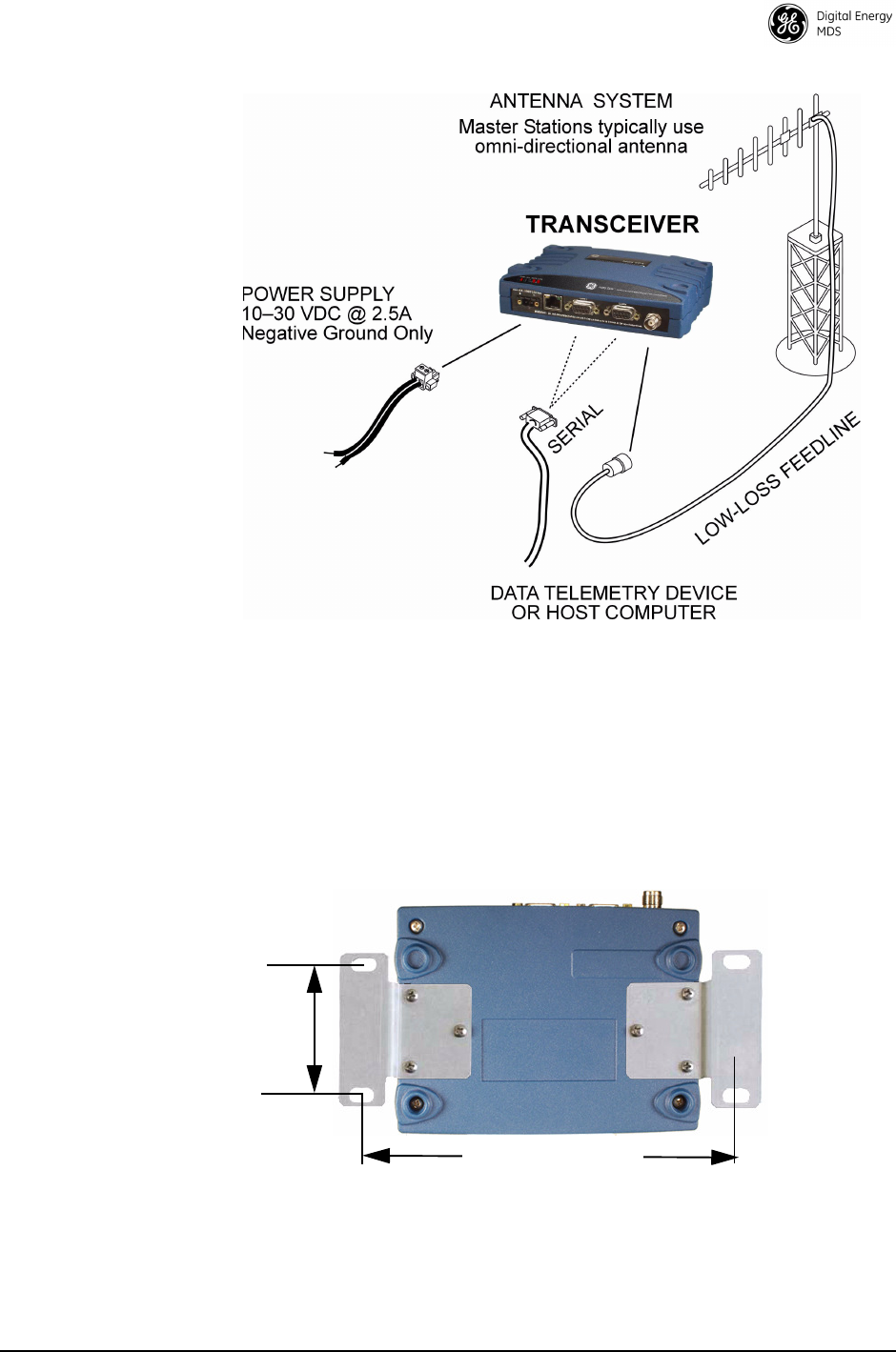
MDS 05-4670A01, Rev. E SD Series Reference Manual (x710 Mode) 9
Figure 6. Typical Remote Station Arrangement
4.2 Mounting Options
The transceiver is normally provided with flat mounting brackets
attached to the bottom of the radio as shown in Figure 7. An optional
35 mm DIN rail mounting bracket is also available. See “Optional DIN
Rail Mounting” on page 10.
Invisible place holder
Figure 7. Mounting Bracket Dimensions
6.675˝ (16.95 cm)
2.75˝ (7 cm)
10 SD Series Reference Manual (x710 Mode) MDS 05-4670A01, Rev. E
NOTE: To prevent moisture from entering the radio, do not mount the
case with the cable connectors pointing up. Also, dress all
cables to prevent moisture from running along the cables and
into the radio.
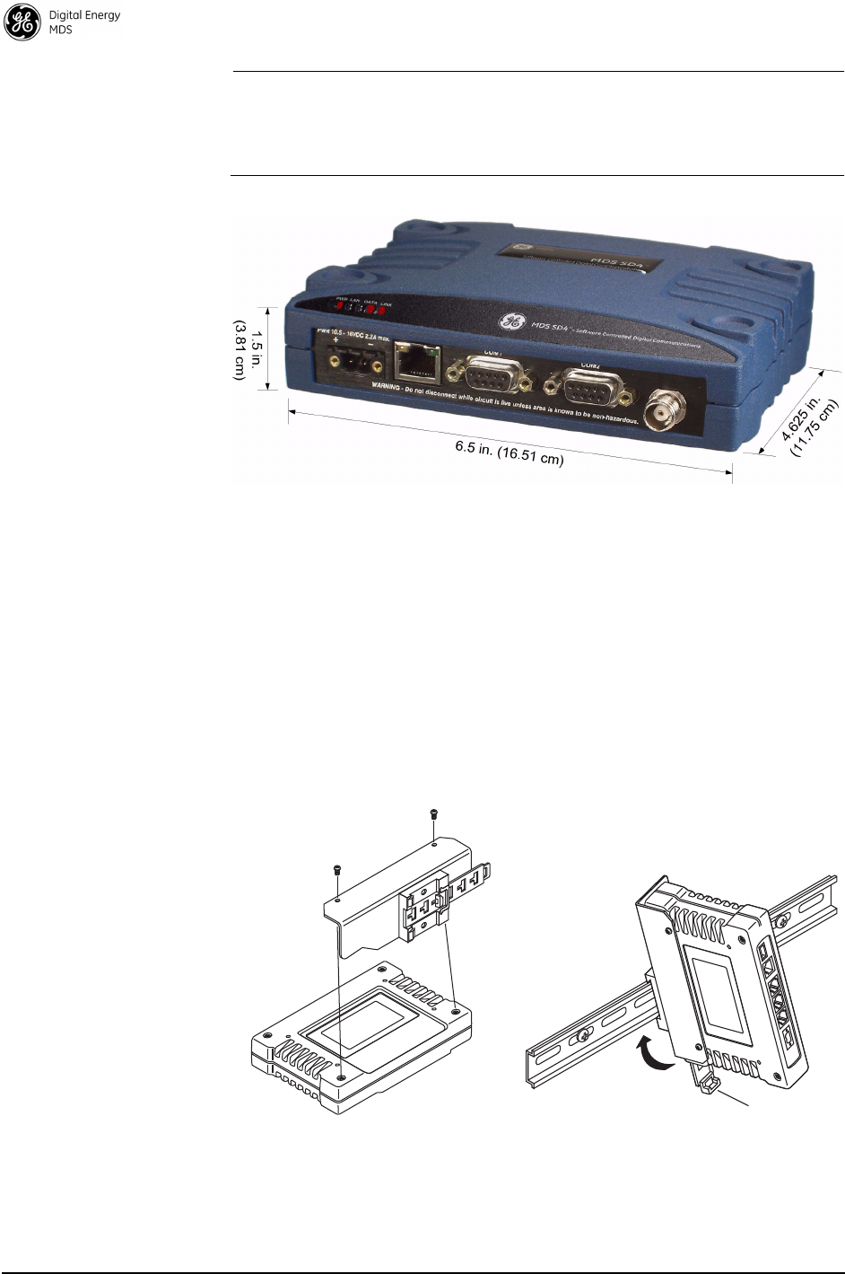
Transceiver dimensions are shown in Figure 8.
Figure 8. SD Transceiver Dimensions
Optional DIN Rail Mounting
The unit can be mounted with an optional 35 mm DIN Rail Mounting
Bracket Kit (Part No. 03-4125A04). Equipment cabinets and racks of
modern design often employ this type of mounting. Once the DIN
bracket is attached to the radio, it allows for quick installation and
removal of the radio from its mounting rail without the need for tools.
The DIN Rail bracket attaches to the unit’s case as shown in Figure 9.
The entire assembly then attaches to the mounting rail.
Figure 9. Attachment & Mounting of DIN Rail Bracket
(unit shown is for example only, and is not an SD Transceiver)
Step 1: Attach the bracket using the Step 2: Clip the assembly onto the
DIN Rail. Removal is performed by
pulling down on the Release Tab.
Release Tab
two screws provided. (Attach to
the end opposite the unit’s connectors.)

MDS 05-4670A01, Rev. E SD Series Reference Manual (x710 Mode) 11
4.3 Antennas and Feedlines
Antennas
The transceiver can be used with a number of antennas. The exact style
depends on the physical size and layout of your radio system. A direc-
tional Yagi (Figure 10) or corner reflector antenna is generally recom-
mended at remote sites to minimize interference to and from other users.
Antennas of this type are available from several manufacturers,
including GE MDS. Contact your factory representative for details.
Invisible place holder
Figure 10. Typical Yagi Antenna (mounted to mast)
Feedlines
The selection of an antenna feedline is very important. Poor quality
cable should be avoided as it will result in power losses that might
reduce the range and reliability of the radio system.
Table 2, Table 3, and Table 4 show the approximate losses that will
occur when using various lengths and types of coaxial cable in the 200,
400, and 900 MHz bands. Regardless of the type used, the cable should
be kept as short as possible to minimize signal loss.
Table 2. Signal Loss in Coaxial Cables (at 200 MHz)
Cable Type
10 Feet
(3.05 Meters)
50 Feet
(15.24 Meters)
100 Feet
(30.48 Meters)
200 Feet
(60.96 Meters)
RG-8A/U 0.26 dB 1.27 dB 2.5 dB 5.07 dB
1/2 inch HELIAX
0.06 dB 0.38 dB 0.76 dB 1.60 dB
7/8 inch HELIAX
0.04 dB 0.21 dB 0.42 dB 0.83 dB
1-1/4 inch HELIAX
0.03 dB 0.16 dB 0.31 dB 0.62 dB
1-5/8 inch HELIAX
0.025 dB 0.13 dB 0.26 dB 0.52 dB
12 SD Series Reference Manual (x710 Mode) MDS 05-4670A01, Rev. E
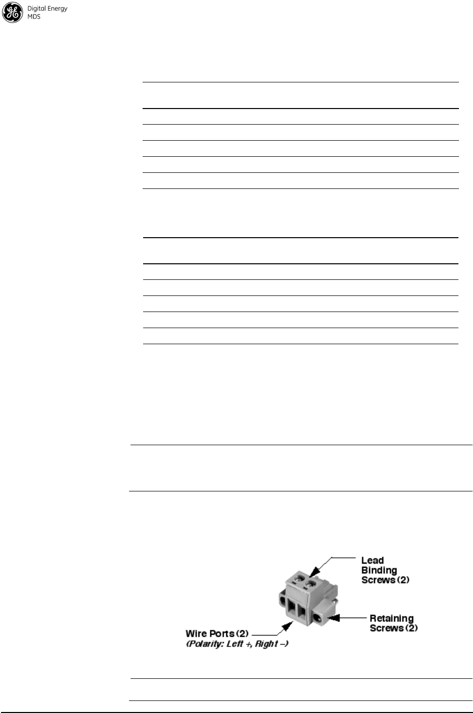
4.4 DC Power Connection
Power the transceiver from any well-filtered 10.0 to 30 Vdc power
source. The supply must be capable of providing at least 2.5 A of con-
tinuous current.
NOTE: Early SD4 models supported 10.5 to 16 Vdc power, not 10 to
30 Vdc. Check the labeling above the power connector to
confirm the operating range for your unit.
A power connector with screw terminals is provided with each unit (see
Figure 11). Strip the wire leads to 6 mm (1/4 inch) and insert in the wire
ports. Be sure to observe proper polarity as shown in Figure 11.
Figure 11. DC Power Connector (P/N 73-1194A39)
NOTE: The radio is designed for use in negative ground systems only.
Table 3. Signal Loss in Coaxial Cables (at 400 MHz)
Cable Type
10 Feet
(3.05 Meters)
50 Feet
(15.24 Meters)
100 Feet
(30.48 Meters)
200 Feet
(60.96 Meters)
RG-8A/U 0.51 dB 2.53 dB 5.07 dB 10.14 dB
1/2 inch HELIAX
0.12 dB 0.76 dB 1.51 dB 3.02 dB
7/8 inch HELIAX
0.08 dB 0.42 dB 0.83 dB 1.66 dB
1-1/4 inch HELIAX
0.06 dB 0.31 dB 0.62 dB 1.24 dB
1-5/8 inch HELIAX
0.05 dB 0.26 dB 0.52 dB 1.04 dB
Table 4. Length vs. Loss in Coaxial Cables (at 900 MHz)
Cable Type
10 Feet
(3.05 Meters)
50 Feet
(15.24 Meters)
100 Feet
(30.48 Meters)
200 Feet
(60.96 Meters)
RG-8A/U 0.85 dB 4.27 dB 8.54 dB 17.08 dB
1/2 inch HELIAX
0.23 dB 1.15 dB 2.29 dB 4.58 dB
7/8 inch HELIAX
0.13 dB 0.64 dB 1.28 dB 2.56 dB
1-1/4 inch HELIAX
0.10 dB 0.48 dB 0.95 dB 1.90 dB
1-5/8 inch HELIAX
0.08 dB 0.40 dB 0.80 dB 1.60 dB

MDS 05-4670A01, Rev. E SD Series Reference Manual (x710 Mode) 13
4.5 Grounding Considerations
To minimize the chance of damage to the transceiver and connected
equipment, a safety ground (NEC Class 2 compliant) is recommended
which bonds the antenna system, transceiver, power supply, and con-
nected data equipment to a single-point ground, keeping all ground leads
as short as possible.
Normally, the transceiver is adequately grounded if the supplied flat
mounting brackets are used to mount the radio to a well-grounded metal
surface. If the transceiver is not mounted to a grounded surface, it is rec-
ommended that a safety ground wire be attached to one of the mounting
brackets or a screw on the transceiver’s case.
The use of a lightning protector is recommended where the antenna
cable enters the building. Bond the protector to the tower ground, if pos-
sible.
4.6 COM1 (Management) Connections
The radio’s
COM1
port is used to connect a PC for management or diag-
nostic purposes. Typically, a straight-through DB-9 cable can be used
for this purpose. If desired, construct a cable as shown in Figure 13, con-
necting Pins 2 (RXD), 3 (TXD), and 5 (GND).
Other custom cables or adapter kits are only needed for analog operation
or other special-use applications.
NOTE:
To prevent unintended keying of the transmitter during management
activities, set PTTSIG to OFF
, or do not connect to Pin 6 of the
COM1
port.
Figure 12. COM1 Connector (DB-9F)
As viewed from outside the radio
5
9 6
1

14 SD Series Reference Manual (x710 Mode) MDS 05-4670A01, Rev. E
Invisible place holder
Figure 13. COM1 Wiring to Computer for Management
COM1 in Analog Operation
The
COM1
port also supports connections for analog operation with an
external modem. Pins 4, 5, 6, and 8 in Table 5 are used for analog oper-
ation. (Pins 7 and 9 are reserved for user I/O signals.) Refer to “Analog
Operation of the Transceiver” on Page 46 for more information.
RXD
TXD
GND
2
3
5
RXD
TXD
GND
2
3
5
<DB-9 FEMALE
(COMPUTER)
DB-9 MALE
(RADIO SIDE)
>
Table 5. COM1 Pin Descriptions
Pin
Number
Input/
Output Pin Description
1 -- No function
2 OUT RXD (Received Data)—Supplies received data to the
connected device.
3 IN TXD (Transmitted Data)—Accepts TX data from the
connected device.
4 -- No function
5 -- Ground—Connects to ground (negative supply potential) on
chassis.
6 -- No function
7 -- No function in most applications—User I/O for special
applications
8 --- No function
9 -- No function in most applications—User I/O for special
applications

MDS 05-4670A01, Rev. E SD Series Reference Manual (x710 Mode) 15
4.7 COM2 (Data) Connections
The
COM2
port (Figure 14) is used to connect the radio to an external
DTE telemetry device supporting the EIA/RS-232 or EIA/RS-485 (bal-
anced) format, depending on how the radio is configured. Typically, a
straight-through DB-9 cable is used to connect to
COM2
. The radio sup-
ports data rates of 300, 1200, 2400, 4800, 9600, 19200, 38400, 57600,
and 115200 bps (asynchronous data only). The following data formats
are supported:
Table 7 and Table 8 provide detailed pin descriptions for the
COM2
data
port
in RS/EIA-232 mode and RS/EIA-485 mode, respectively.
NOTE:
Make sure the PORT setting from the PORT command matches the
type of interface you are using (RS-232 or RS-485). The default is
RS-232.
NOTE:
To prevent unintended keying of the transmitter on RTS, set
RTSKEY to OFF
, or
do not connect to Pin 7 (RTS) of the
COM2
port.
Pin Descriptions—
RS/EIA-232 Mode
Table 7 lists the
COM2
port pin functions when configured to operate in
RS/EIA-232 mode.
NOTE: The radio is hard-wired as a DCE device.
Table 6. Data Formats
Character Bits Parity Stop Bits
8 No 1
8 No 2
8 Odd 1
8 Odd 2
8 Even 1
8 Even 2
7 No 1
7 No 2
7 Odd 1
7 Odd 2
7 Even 1
7 Even 2
Figure 14. COM2 Connector (DB-9F)
As viewed from outside the radio
5
9 6
1

16 SD Series Reference Manual (x710 Mode) MDS 05-4670A01, Rev. E
Pin Descriptions—
RS/EIA-422/485
Mode
Table 8 lists the
COM2
port pin functions for radios configured to operate
in RS/EIA-422/485 mode. See Figure 15 for wiring schemes.
Table 7. COM2 Pin Descriptions—RS/EIA-232 Mode
Pin
Number
Input/
Output Pin Description
1 OUT DCD (Data Carrier Detect/Link)—A high (asserted)
indicates signal received.
2 OUT RXD (Received Data)—Supplies received data to the
connected device.
3 IN TXD (Transmitted Data)—Accepts TX data from the
connected device.
4 IN Sleep Mode Input—Grounding this pin places the radio in a
low power consumption mode.
5 -- Signal Ground—Connects to ground (negative supply
potential) on chassis.
6 OUT Alarm Output (DSR)—Behavior is user-configurable. Default
behavior: An RS-232 high/space (+5.0 Vdc) on this pin
indicates an alarm condition. An RS-232 low/mark (–5.0 Vdc)
indicates normal operation.
7 IN RTS (Request-to-Send)—Keys the transmitter.
8 OUT CTS (Clear-to-Send)—Goes “high” after the programmed
CTS delay time has elapsed (DCE), or keys another
connected radio when RF data arrives (CTS KEY).
9 -- Reserved—User I/O for special applications.
Table 8. COM2 Connector Pin Descriptions—RS/EIA-422/485
Mode
Pin
Number
Input/
Output Pin Description
1 OUT Carrier Detect/Link—A high indicates signal received.
2 OUT TXD-/TXA (Transmitted Data -)—Inverting driver output.
Supplies received payload data to the connected device.
3 IN RXD-/RXA (Received Data -)—Inverting receiver input.
Accepts payload data from the connected device.
4 IN Sleep Mode Input—Grounding this pin places the radio in a
low power consumption mode.
5 -- Ground—Connects to ground (negative supply potential) on
the radio’s PC board.
6 OUT Alarm Output—Behavior is user-configurable. Default
behavior: A high on this pin indicates an alarm condition; a low
indicates normal operation.
7 IN RXD+/RXB (Received Data +)— Non-inverting receiver input
8 OUT TXD+/TXB (Transmitted Data +)—Non-inverting driver output.
9 -- Reserved—User I/O for special applications

MDS 05-4670A01, Rev. E SD Series Reference Manual (x710 Mode) 17
COM2 PORT NOTES:
•
RXD+ / RXB and RXD– / RXA are data sent to the radio to be transmitted
• RXD+ / RXB is positive with respect to RXD– / RXA when the line input is a “0”
• TXD+ / TXB and TXD– / TXA are data received by the radio and transmitted
• TXD+ / TXB is positive with respect to the TXD– / TXA when the line output is a “0”
Invisible place holder
Figure 15. EIA-422/485 Wiring Arrangements
4.8 Ethernet Interface (RJ-45)
In x710 mode, the transceiver’s Ethernet Port is used for radio manage-
ment only. The port has built-in MDIX (auto-sensing) capability,
allowing either a straight-through or crossover cable to be used.
Figure 16 and Table 9 show pinout data for the Ethernet port.
The Ethernet port can be used to support Telnet or web-based radio
management. Telnet provides the same user interface available with
COM1
.
Figure 16. Ethernet Port (RJ-45) Pinout
(As viewed from the outside of the unit)
Table 9. Ethernet Port (IP/Ethernet) Pinouts
Pin Functions Ref.
1 Transmit Data (TX) High
2 Transmit Data (TX) Low
3 Receive Data (RX) High
4 Unused
5 Unused
6 Receive Data (RX) Low
7 Unused
8 Unused
EIA-485 2-WIRE CONNECTIONS
TXD
RXD
2
3
7
RADIO
DATA CONNECTOR
8
RXD +
TXD +
EIA-422 4-WIRE CONNECTIONS
RXD/TXD
2
3
7
RADIO
DATA CONNECTOR
8
RXD+/TXD+
EXTERNAL DEVICE
EXTERNAL DEVICE
RXD +
TXD
RXD
TXD +
RXD +
TXD
RXD
TXD +
This jumpering must be provided by user.
812
3
4
56
7

18 SD Series Reference Manual (x710 Mode) MDS 05-4670A01, Rev. E
5.0 STEP-BY-STEP INSTALLATION
In most cases, the steps given here are sufficient to install the trans-
ceiver. Refer to “INSTALLATION PLANNING” on Page 8 for addi-
tional details.
1. Mount the transceiver. Attach the mounting brackets to the bottom
of the transceiver case (if not already attached), using the four 6-32
x 1/4 inch (6 mm) screws supplied. Mounting bracket dimensions
are shown in Figure 7 on page 9. Secure the brackets to a flat,
grounded surface. (If a grounded surface is not available, run a
separate ground wire to the transceiver—see “Grounding
Considerations” on Page 13.)
2. Install the antenna and feedline. The antenna used with the radio
must be designed to operate in the radio’s frequency band, and be
mounted in a location providing a clear path to the associated sta-
tion(s). At Remote sites, aim directional antennas toward the master
unit. Use low-loss coaxial feedline, and keep the feedline as short as
possible.
3. Connect the data equipment. Make the connection using Serial
protocols (RS-232/RS-485).
Connect a serial device to COM2 on the front panel. The radio is
hardwired as a DCE device. Use a straight-through cable for most
applications.
4. Connect primary power. Input power must be within the range
printed above the power connector, and capable of providing at least
2.5 A. A power connector with screw-terminals is provided with the
unit (see Figure 11 on page 12). Strip the wire leads to 1/4 inch
(6 mm) and insert them into the wire ports. Be sure to observe
proper polarity. Tighten the binding screws securely.
The unit is designed for use with negative-ground sys-
tems only. The power supply should be equipped with
overload protection (NEC Class 2 rating), to protect
against a short circuit between its output terminals
and the radio’s power connector.
NOTE: To comply with IEC61850-3, paragraph 5.7.1.2, surge
suppression must be used across the power supply for Class 3
and 4 severity levels as defined by IEC 61000-4-5 Annex A.
CAUTION
POSSIBLE
EQUIPMENT
DAMAGE
MDS 05-4670A01, Rev. E SD Series Reference Manual (x710 Mode) 19
5.1 Initial Startup & Checkout
In-service operation of the transceiver is completely automatic. Once
the unit has been properly installed and configured, operator actions are
limited to observing the front panel LED indicators for proper operation.
If all parameters are correctly set, operation of the radio can be started
by following these steps:
1. Apply DC power.
2. Observe the LED status panel for proper indications (Table 10).
3. If not done earlier, refine the antenna heading of the station to maxi-
mize the received signal strength (RSSI) from the Master Unit. The
RSSI
command can be used to display signal strength. Turn the
antenna heading slowly so that the RSSI display can be updated.
NOTE: The RSSI function limits the maximum displayed signal
strength to –60 dBm.
Invisible place holder
5.2 Initial Software Configuration
This section provides the steps necessary to program the radio for its
first on-air operation. There are numerous settings that go beyond basic
configuration, and you may wish to access these later. A full description
of commands is provided in “TRANSCEIVER MANAGEMENT” on
Page 21.
Table 10. LED Status Indicators
(LED labeling may vary on early units; functionality remains as
described below)
LED Name Description
PWR • Continuous—Power applied, no problems detected.
• Rapid flash (5 times-per-second)—Alarm indication, or
RX/TX frequencies not set.
LAN • Flashing—Data is being transmitted and received.
• Off—Ethernet signals not detected
DATA 1/DATA 2 These LEDs show data activity on the DB-9 serial payload
ports (
COM1
and
COM2
).
LINK When lit, indicates that a communication link exists with the
Master Unit.

20 SD Series Reference Manual (x710 Mode) MDS 05-4670A01, Rev. E
Serial vs. Telnet Access, and the Device Manager
There are three methods available to communicate with the transceiver
for configuration and management purposes: Serial (
COM1
DB9 con-
nector), Telnet (
ETHERNET
RJ-45 connector), and the web-based
Device Manager. Both serial and telnet present identical screens, but
the method of access is different for each. The Device Manager provides
a web interface using the transceiver’s built-in web server, and is the
newest configuration interface, although all three options accomplish
the same results.
NOTE: Firmware reprogramming is best handled using the Device
Manager.
The focus of this section is on Serial access, but Telnet may also be used
by following these additional points, which replace Steps 1-3 below:
• Connect to the radio with a PC that is on the same IP network as
the transceiver. Launch a Telnet program, and connect to the
radio using its programmed IP address.
• The default IP address for an SD is 192.168.1.1. If you do not
know the IP address of the radio, follow the serial configuration
instructions below, where you can determine the radio’s address
and continue configuration of the radio, or ask your network
administrator.
Connecting a PC & Setting Basic Parameters
Follow these steps to configure the transceiver for its first use:
1. Connect a PC to the radio’s
COM1
serial port as shown in Figure 17.
(Maximum recommended cable length: 50 ft./15 m)
NOTE: Not all PCs include a serial port. If one is not available, a USB
port may be used, along with a USB-to-Serial adapter (with
appropriate driver software). Adapters are available from
many manufacturers.
NOTE: If
COM1
has been configured to boot into data mode, pressing
within 10 seconds of boot-up switches it into console
(management) mode. Console mode is required for the
following steps.
2. Launch a terminal communications program, such as HyperTer-
minal (included with many Windows
®
-based PCs) with the fol-
lowing communication parameters: 8 bits, no parity, one stop bit
(8N1), flow control disabled, VT100 emulation. The radio’s
COM1
port automatically determines the connected baud rate (within the
range of 1200–115200 bps). The preferred baud rate is 9600 bps.
ENTER

MDS 05-4670A01, Rev. E SD Series Reference Manual (x710 Mode) 21
3. Press the
key
several times at half-second intervals to
choose and select the correct baud rate. This will result in
the >
prompt.
Invisible place holder
Figure 17. PC Connection to Transceiver
NOTE: TX and RX frequencies might not be set when the radio is
shipped from the factory, depending on ordering options. If
frequencies have not been set, the
PWR
LED will flash, indi-
cating an alarm condition. The alarm will clear after the
frequencies are set. In all cases, users should verify that the
frequencies are properly set in accordance with the station
license.
6.0 TRANSCEIVER MANAGEMENT
To perform transceiver management, connect a PC as described in
Section 5.1, Initial Startup & Checkout and obtain the
>
prompt.
6.1 Software Commands
Table 11 is a reference chart of software commands for the transceiver.
Programmable information is shown in brackets [ ] following the com-
mand name. See Section 6.2, Detailed Command Descriptions (Page
21) for detailed command descriptions.
Entering Commands
To enter a command, type the command, followed by . For pro-
gramming commands, the command is followed by and the
appropriate information or values, then
.
Table 11. Command Summary
Command name Function
AK Details Page 25 The Authorization Key and a list of authorized
features.
ALARM Details Page 25 Read current operating condition of radio.
AMASK [0000 0000–FFFF
FFFF] Details Page 25
Set/display hex code identifying which events
trigger an alarm.
ENTER
PC Running Terminal Session
Transceiver
DB-9M to COM1 Port
ENTER
SPACE
ENTER

22 SD Series Reference Manual (x710 Mode) MDS 05-4670A01, Rev. E
ASENSE [HI, LO] Details
Page 25
Set/display the state of the alarm output signal to
ACTIVE HI or ACTIVE LO.
AUDIO [ON, OFF] Details
Page 26
Set/display the receive audio monitor mode for
modems.
BAUD [xxxxx abc] Details
Page 26
Set/display the DATA INTERFACE data rate and
format.
BIN [DATA, CLEAR]
Details Page 26
Display or clear data counters.
BOOT Details Page 26 Used to initiate a software reboot.
BUFF [ON, OFF] Details
Page 26
Enables or disables the internal radio data buffer.
CKEY [ON–OFF] Details
Page 27
Enables or disables the continuously keyed
mode. Note: Remotes cannot receive when
keyed.
CTS [0–255] Details Page
27
Set/display the Clear-to-Send delay in seconds.
CTSHOLD [0–60000]
Details Page 27
Set/display Clear-to-Send hold delay.
DATAKEY [ON, OFF]
Details Page 28
Enables or Disables key-on-data mode
(ON = key-on-data or RTS, OFF = key-on-RTS).
DEV Details Page 28 Set/display modem control deviation.
DEVICE [DCE, CTS KEY]
Details Page 28
Set/display device mode.
DKEY Details Page 28 Dekey the radio (transmitter OFF). This is
generally a radio test command.
DLINK [ON/OFF/xxxx]
Details Page 28
Configures local diagnostic link protocol.
DTYPE [NODE/ROOT]
Details Page 29
(diagnostics) Sets up a radio as a root or node
radio.
DUMP Details Page 29 Display all programmable settings.
EMP [ON/OFF] Details
Page 29
Set/display TX audio pre-emphasis for analog
mode.
ETHADDR Details Page 29 Displays Ethernet MAC address
(non-configurable).
FORCEALARM [ON or
OFF] Details Page 29
Generates a test alarm for 10 sec.
FORCEDCD [ON or OFF]
Details Page 29
Forces Data Carrier Detect (DCD) to always be
asserted.
HELP Details Page 29 Shows available commands.
INIT Details Page 30 Set radio parameters to factory defaults for the
radio outside the P-20 Protected Network
Chassis.
INIT [SDx] Details Page 30 Configure radio for use outside of the Protected
Network Chassis (SDxP). Restores certain
transceiver defaults changed by the INIT P-20
command.
Table 11. Command Summary (Continued)
Command name Function

MDS 05-4670A01, Rev. E SD Series Reference Manual (x710 Mode) 23
INIT [P-20] Details Page 30 Configure radio for service within a P-20
Protected Network Chassis.
IPCONFIG Details Page 31 Ethernet interface configuration.
KEY Details Page 31 Key the radio (transmitter ON). This is generally a
radio test command.
MENU Details Page 31 Activates the radio’s menu-based program (if
supported).
MODEL1 Details Page 31 Shows configuration order entry string associated
with the radio. Programmed at the factory.
MODEL2 Details Page 31 Shows an identifier string associated with the
radio’s hardware bill of materials and revision.
Programmed at the factory.
MODEM [xxxx] Details
Page 31
Set the modem characteristics of the radio.
OWM [XXX...] Details Page
33
Set/display the owner’s message.
OWN [XXX...] Details Page
33
Set/display the owner’s name.
PORT [RS232, RS485]
Details Page 34
Set/display COM2 data port interface settings.
PTT [0–255] Details Page
34
Set/display the Push-to-Talk delay in
milliseconds.
PTTSIG [OFF, LOW, HI]
Details Page 34
Set/display push-to-talk configuration.
PWR [20–37] Details Page
34
Set/display the transmit power setting.
RESTORECONFIG Details
Page 34
Restores a saved user configuration.
RESTOREDEFAULTS
Details Page 34
This command restores the original factory
configuration.
RMODE [X710,
TRANSPARENT,
PACKET, CMAC, HELP]
Details Page 34
Allows the reconfiguration of the SD operating
mode.
RSSI Details Page 34 Display the Received Signal Strength Indication.
RTSKEY [ON, OFF] Details
Page 35
Set/display how the radio responds to RTS
keying. Default is RTSKEY OFF, to prevent
undesired keying of the transmitter when RTS is
raised by a terminal program.
RTU [ON/OFF/0-80] Details
Page 35
Re-enables or disables the radio’s internal RTU
simulator and sets the RTU address.
RX [xxx.xxxx] Details
Page 35
Set/display receiver frequency.
RXATTN [ON or OFF]
Details Page 35
Enables or disables receive attenuation.
RXLEVEL [–20 to 0]
Details Page 35
Set/display the receive audio input level.
Table 11. Command Summary (Continued)
Command name Function

24 SD Series Reference Manual (x710 Mode) MDS 05-4670A01, Rev. E
6.2 Detailed Command Descriptions
The only critical commands for most applications are transmit and
receive frequencies (
TX xxx.xxxx, RX xxx.xxxx
) and Modem configuration
(
MODEM xxxx
) settings. However, proper use of the additional commands
allows you to tailor the transceiver for a specific use, or conduct basic
diagnostics on the radio. This section provides detailed information for
the user commands previously listed in Table 11 (Page 21).
RXTOL [NORMAL or
CUSTOM] Details Page
36
Set/display the custom receive tolerance to
accommodate issues experienced with some
x790 masters.
RXTOT [NONE, 1-1440]
Details Page 36
Set/display the value of the receive time-out timer.
SAVECONFIG Details
Page 36
Saves a user configuration.
SCD [0-255] Details Page
36
Set/display the Soft-Carrier Dekey delay in
milliseconds.
SER Details Page 36 Display the radio serial number.
SHOW [DC, PWR] Details
Page 36
Display the DC voltages and transmit power level.
SNR Details Page 36 Signal-to-Noise Ratio, expressed in dB.
SPECTRUM [xxx.xx]
Details Page 37
Display the transceiver’s built-in spectrum
analyzer, where xxx.xx denotes center frequency.
SQUELCH [AUTO,
BYPASSED] Details
Page 37
Set/display analog squelch bypass.
SREV Details Page 37 Display the Software Revision Level.
STAT Details Page 38 Display radio status and alarms.
SWC [ON, OFF] Details
Page 38
Switched Carrier configuration.
TFTP Details Page 38 Set/display all TFTP settings.
TEMP Details Page 38 Display the internal temperature of the radio in
degrees C.
TOT [1-255, ON, OFF]
Details Page 39
Set/display the Time-out Timer delay in seconds.
TX [xxx.xxxx] Details Page
39
Set/display the transmit frequency.
TXLEVEL [–20 to 0, AUTO]
Details Page 39
Set/display the transmit audio input level.
UNIT [10000...65000]
Details Page 39
Set/display the transceiver’s unit address.
UPTIME Details Page 39 Displays time since last system reboot.
VERSION Details Page 39 Displays firmware package information.
Table 11. Command Summary (Continued)
Command name Function

MDS 05-4670A01, Rev. E SD Series Reference Manual (x710 Mode) 25
In many cases, the commands shown here can be used in two ways:
• Type only the command name to view the currently programmed
data.
• Set or change the existing data by typing the command, followed
by a space, and then the desired entry.
In the list below, allowable programming variables, if any, are shown in
brackets following the command name.
Authorization Key
AK
The transceiver’s feature set may be expanded (if all features are not
currently enabled) by entering a new authorization key, which can be
purchased from GE MDS. Contact the factory to obtain a new Authori-
zation Key.
ALARM
Alarm Summary
The
ALARM
command displays a summary of the radio’s current oper-
ating condition. An eight-digit code is presented which can be decoded
as described in “Major Alarms vs. Minor Alarms” on Page 41.
AMASK [0000 0000–FFFF FFFF]
Alarm Mask
The
AMASK
command displays or sets which events cause an alarm
output signal to be active. Normally, the mask is
FFFF FFFF
, meaning that
any of the 32 possible events will activate the alarm output signal.
Entering the
AMASK
command alone displays the current setting of alarm
events in hexadecimal format.
Entering the
AMASK
command followed by an eight-digit hexadecimal
number reprograms the specified events to trigger an alarm.
The eight-digit hexadecimal number used as the command parameter
specifies 0 to 32 events that can trigger the external alarm output. (See
Table 14 on Page 41 for a list of events.) The hex value for the mask cor-
responds to the hex value for the
STAT
command (Page 38). Each bit that
is a ‘1’ identifies an alarm condition that can trigger the external output.
For more information on configuring the alarm response, contact GE
MDS
.
ASENSE [HI, LO]
Alarm Sense
The
ASENSE
command sets or displays the sense of the alarm output at
Pin 6 of the
COM2
port.
Entering the
ASENSE
command alone shows whether the alarm output is
active high or low. Entering the
ASENSE
command followed by
HI
or
LO
resets the alarm output to active high or low.

26 SD Series Reference Manual (x710 Mode) MDS 05-4670A01, Rev. E
AUDIO [ON, OFF]
Audio Monitor/
Orderwire Status
Used to set or display Audio Monitor/Orderwire functionality (on or
off). If
AUDIO ON
is selected, the radio’s transmit functionality will
switch to analog whenever PTT is asserted.
BAUD [xxxxx abc]
Data Interface Port
Baud Rate
This command sets (or displays) the communication attributes for the
DATA INTERFACE
port (COM2). It has no effect on the
COM1
manage-
ment port.
The first parameter (
xxxxx
) is baud rate. Baud rate is specified in
bits-per-second (bps) and must be one of the following speeds: 300,
1200, 2400, 4800, 9600, 19200, 38400, 57600, or 115200 bps.
The second parameter of the
BAUD
command (
abc
) is a three-character
block indicating how the data is encoded:
a
= Data bits (7 or 8)
b
= Parity (N for None, O for Odd, E for Even)
c
= Stop bits (1 or 2)
The factory default setting is 9600 baud, 8 data bits, no parity, 1 stop bit
(Example:
9600 8N1
).
BIN [DATA, CLEAR]
Data Counters
Used to display or clear the data counters. Use
BIN DATA
to display. Use
BIN CLEAR
to clear the counters.
BOOT
Software Reboot
Used to initiate a software reboot. Use
BOOT
alone to reboot the cur-
rently running firmware image. Use
BOOT 1
,
BOOT 2
, or
BOOT OTHER
to
reboot to a specific firmware image.
BUFF [ON, OFF]
RX Data Buffer
This command sets or displays the received data handling mode of the
radio. The command parameter is either
ON
or
OFF
. The default is
ON
.
The setting of this parameter affects the timing of how received RF data
is sent from the
DATA INTERFACE
connector. Outgoing (transmitted)
data is not affected by this setting.
If data buffering is
OFF
, the radio operates with the lowest possible
average latency. Data bytes are sent from the
DATA INTERFACE
port as
soon as an incoming RF data frame is disassembled. Average and typ-
ical latency will be minimized, but idle character gaps may be intro-
duced into the outgoing data flow.

MDS 05-4670A01, Rev. E SD Series Reference Manual (x710 Mode) 27
If data buffering is
ON
, the radio operates in seamless mode. Data bytes
are sent over the air as quickly as possible, but the receiver buffers
(stores) the data until enough bytes have arrived to cover worst-case
gaps in transmission. This mode of operation is required for protocols
such as MODBUS™ that do not allow gaps in their data transmission.
NOTE: Seamless mode (
BUFF ON
) is intended only for applications
where the transmitter’s baud rate is greater than or equal to the
receiver’s baud rate. Enforcement of this rule is the user’s
responsibility.
CKEY [ON–OFF]
Key TX
Continuously
The
CKEY
command enables or disables the continuously-keyed func-
tion of the radio. When
CKEY
is set to
ON
, the radio is continuously keyed
and the Timeout Timer is disabled.
CTS [0–255]
Clear-to-Send Time
The
CTS
(clear-to-send) command selects or displays the timer value
associated with the CTS line response. The command parameter ranges
from 0 to 255 milliseconds.
For DCE operation, the timer specifies how long to wait after the RTS
line goes high, before the radio asserts CTS and the DTE can transmit
the data. A CTS value of zero keys the radio and asserts the CTS line
immediately after the RTS line goes high.
For CTS Key operation (see
DEVICE
command), the timer specifies how
long to wait after asserting the CTS, before sending data from the
DATA
INTERFACE
port. A timer value of zero means that data will be sent from
the data port without imposing a key-up delay. (Other delays might be
present based on selected radio operating parameters.)
CTSHOLD [0–60000]
Clear-to-Send Hold
Time
Used in
DEVICE CTS KEY
mode, this command sets the amount of time in
milliseconds that CTS remains present after transmission of the last
character from the RXD pin of the
DATA
port. This “hold time” can be
used to prevent squelch tail data corruption when communicating with
other radios.
The
CTSHOLD
setting can range from 0 to 60000 ms (60 seconds). The
default value is 0, which means that CTS will drop immediately after the
last character is transmitted. If the command is entered when the radio
is in
DEVICE DCE
mode, the response
CTSHOLD N/A
is shown.

28 SD Series Reference Manual (x710 Mode) MDS 05-4670A01, Rev. E
DATAKEY [ON, OFF]
Key on Data Activity
The
DATAKEY
command enables or disables the ability of the radio to key
the transmitter as data is received at the
DATA INTERFACE
connector.
Asserting RTS keys the radio regardless of this command setting.
If
DATAKEY
is set to
ON
, the radio will key when a full data-character is
received at the transceiver’s
DATA INTERFACE
connector. If
DATAKEY
is
set to
OFF
, the radio needs to be keyed by asserting RTS.
DEV
Modem Deviation
Displays modem control deviation in Hertz (Hz). This is a read-only
command, and cannot be changed in the field.
DEVICE [DCE, CTS KEY]
Data Device Mode
The
DEVICE
command controls or displays the device behavior of the
radio. The command parameter is either
DCE
or
CTS KEY
.
In
DCE
mode (the default setting), CTS will go high following RTS, sub-
ject to the CTS programmable delay time. If the
DATAKEY
command is
set to
ON
, keying can be stimulated by the input of characters at the data
port. Hardware flow control is implemented by signaling the CTS line if
data arrives faster than it can be buffered and transmitted.
In
CTS KEY
mode, the SD is assumed to be controlling another radio. The
SD will still key based on the RTS line, but the CTS line is used as a key-
line control for the other radio. CTS is asserted immediately following
the receipt of RF data, but data will not be sent out the
DATA INTERFACE
port until after the CTS programmable delay time has expired. (This
gives the other radio time to key.)
DKEY
Unkey Transmitter
This command deactivates the transmitter after it has been keyed with
the
KEY
command.
DLINK [ON/OFF/xxxx]
Diagnostic Link
Use this command to configure the local diagnostic link protocol used
in network-wide diagnostics.
Entering
DLINK ON
enables the diagnostic link. Entering
DLINK OFF
dis-
ables the diagnostic link.
To change the diagnostic link, enter
DLINK
followed by one of the fol-
lowing baud rates: 1200, 2400, 4800, 9600, 19200 (default), 38400,
57600, 115200.

MDS 05-4670A01, Rev. E SD Series Reference Manual (x710 Mode) 29
NOTE: The radio is configured by default to be in DLINK mode. The
COM1
port automatically determines the connected baud rate
(within the range of 1200–115200 bps). Enter a series of
Return Key presses about a half second apart until the
>
prompt
appears. This indicates that the radio is ready to receive
commands.
DTYPE [NODE/ROOT]
Unit’s Diagnostics
Type
This command establishes the local radio as a root radio or node radio
for network-wide diagnostics. Entering
DTYPE NODE
configures the
radio as a node radio. Entering
DTYPE ROOT
configures the radio as a root
radio. Entering the
DTYPE
command alone displays the current setting.
DUMP
Read Current Unit
Profile
This command causes all of the programmed settings to be displayed.
EMP [ON/OFF]
Modem TX Audio
Pre-Emphasis
This command displays or sets the TX pre-emphasis and RX
De-Emphasis when the radio is operating with the analog mode and the
radio’s MODEM is turned off (
MODEM NONE
). It should be set to match
the other radios in the system. The use of pre- and de-emphasis can help
reduce the detrimental influence of high frequency audio noise.
ETHADDR
Ethernet Address
Displays programmed Ethernet MAC address (set at the factory).
FORCEALARM [ON or OFF]
Force Alarm
Generates a test alarm for 10 sec. Use to test alarm outputs and
switch-over in redundant systems.
FORCEDCD [ON or OFF]
Force DCD
Forces Data Carrier Detect (DCD) to always be asserted. Use when con-
necting to equipment that requires a constant DCD indication.
HELP
User Help
Show available commands.

30 SD Series Reference Manual (x710 Mode) MDS 05-4670A01, Rev. E
INIT
Initialize EEPROM
Defaults
The
INIT
command is used to re-initialize the radio’s operating parame-
ters to the factory defaults. This can be helpful when trying to resolve
configuration problems that might have resulted from the entry of one
or more improper command settings. If you are unsure of which com-
mand setting caused the problem, this command allows you to get back
to a known working state. The following changes to the radio are made
when
INIT
is entered:
•
CTS
is set to 0
•
DATAKEY
is set to
ON
•
DEVICE
is set to
DCE
•
PTT
is set to 0
•
SCD
is set to 0
•
TOT
is set to 30 seconds and set to
ON
•
PWR
is set to +37 dBm (5 watts)
All other commands remain as previously set.
INIT [SDx]
(Where “x” denotes SD radio model)
Initialization (for
standalone radio)
This command sets the transceiver for “normal” operation outside the
P-20 chassis by setting the following parameters to the values shown
below:
ASENSE ACTIVE HI
AMASK FFFF FFFF
(assert alarm output on all alarms)
RXTOT NONE
(receive time-out timer disabled)
Use this command to restore these three parameters to the standard
transceiver defaults if it was previously used in a P-20 package.
INIT [P-20]
Initialization for P-20
Implementation
This command sets the transceiver for service inside a P-20 redundant
chassis by setting the following parameters to the values shown below:
ASENSE ACTIVE LO
AMASK FFFF 0000
(trigger on major alarms)
RXTOT 20
(20 minute receive time-out timer)

MDS 05-4670A01, Rev. E SD Series Reference Manual (x710 Mode) 31
IPCONFIG
Ethernet
Configuration
Ethernet interface configuration. This command is used to display or
change the configuration of the Ethernet interface. The command can be
used in several ways:
•
IPCONFIG
alone displays all current network settings.
•
IPCONFIG DHCP [ON/OFF]
is used to switch between DHCP and
static addressing.
•
IPCONFIG IP [ipaddr]
is used to set a static IP address.
•
IPCONFIG NET [netmask]
and
IPCONFIG GW [Gateway]
are used to set
subnet mask and gateway, respectively.
KEY
TX Key
This command activates the transmitter. See also the
DKEY
command.
MENU
Menu Activate
Activates the menu-based program within the transceiver (when sup-
ported), used for reprogramming the unit’s firmware.
MODEL1
Displays the factory software configuration of the radio.
MODEL2
Displays the hardware configuration bill of material identifier.
Model Number
Information
See Table 11 on Page 21 for information on these pre-programmed
fields.
MODEM [xxxx]
Analog/Digital
Modem Selection
This command selects the radio’s modem characteristics. For digital
operation enter
MODEM xxxx
, where
xxxx
equals the modem selection of
the radio. Table 12 shows the supported modem types.
NOTE:For compatibility with an existing MDS x710 system, make sure
to select the matching
MODEM
type. See Table 11.
Table 12. Modem Selection vs. Speed, Bandwidth & Sensitivity
Modem Type
Selection
Over-the-air
Speed (bps)
B/W (kHz) Approximate
Sensitivity
5
Modem 9600
1
9600 12.5 -112 dBm
Modem 4800
1, 2
4800 12.5 -112 dBm
Modem 3200
1, 3
3200 5.00 -108 dBm
Modem 9600M
1, 2
9600 12.5 -106 dBm

32 SD Series Reference Manual (x710 Mode) MDS 05-4670A01, Rev. E
1) For MDS x710-compatible operation.
2) For ETSI compliance.
3) 3200 bps not applicable to SD4.
4) Only available for SD2 and SD9 units with wide bandwidth hardware option.
Sensitivity is -104 dBm for SD2 and -100 dBm for SD9.
5) SD1 sensitivity may be up to 2 dB less, due to MDS 1710 interoperability
constraints.
For analog operation with an external modem, enter
NONE
for this
parameter. When the
MODEM
is set to
NONE
, the analog TX Input and RX
Audio outputs of the
DATA INTERFACE
are used to interface with the
connected external modem, and digital operation is disabled. These
levels must be set to complement the audio signal level requirements of
the external modem. See “RXLEVEL [–20 to 0]” on page 35 and
“TXLEVEL [–20 to 0, AUTO]” on Page 39 for details on setting these
levels.
Modem 4800F 4800 6.25 -108 dBm
Modem 9600B
1
9600 12.5 -106 dBm
Modem 4800B
1
4800 12.5 -110 dBm
Modem BELL
1
1200 12.5 -110 dBm
Modem V23 1200 12.5 -110 dBm
Modem 19200N 19200 12.5 -100 dBm
Modem 19200E
2
19200 12.5 -96 dBm
Modem 9600N 9600 6.25 -98 dBm
Modem 19200 19200 25.0 -105 dBm
Modem 38400N 38400 25.0 -99 dBm
Modem 65000
4
65000 50.0 -102 dBm
Modem NONE For analog operation with an external modem.
See text.
Table 12. Modem Selection vs. Speed, Bandwidth & Sensitivity
Modem Type
Selection
Over-the-air
Speed (bps)
B/W (kHz) Approximate
Sensitivity
5

MDS 05-4670A01, Rev. E SD Series Reference Manual (x710 Mode) 33
When the transceiver is used to replace an existing MDS x710 radio, it
is important to verify that the modem selection is compatible with the
unit replaced. Table 13 lists SD modem type selections and the compat-
ible x710 models they can be used with.
OWM [XXX...]
Owner’s Message
This is a command to show or program an owner’s message. To pro-
gram the owner’s message, type
OWM
then the message, followed by
.
To show the owner’s message, type
OWM
then . The owner’s
message appears on the display.
OWN [XXX...]
Owner’s Name
This is a command to show or program an owner’s name. To program
the owner’s name, type
OWN
then the name, followed by .
To show the owner’s name, type
OWN
then . The owner’s name
appears on the display.
Table 13. Modem Compatibility with MDS x710 Radios
SD Modem Type
Selection
Compatible with
MDS x710 Models
Modem 9600 2710A, 4710A, 9710A
Modem 4800 4710E, 9710E
Modem 3200 2710D
Modem 9600M 4710M, 9710M
Modem 4800F --
Modem 9600B 4710B, 9710B
Modem 4800B 4710B, 9710B
Modem BELL 4710B, 9710B
Modem V23 --
Modem 19200N --
Modem 19200E --
Modem 9600N --
Modem 19200 2710C, 4710C, 9710C
Modem 38400N --
Modem 65000 --
Modem NONE x710A / x710C / x710E
“modem none”
MPT1411 x710M “modem none”
ENTER
ENTER
ENTER
ENTER

34 SD Series Reference Manual (x710 Mode) MDS 05-4670A01, Rev. E
PORT [RS232, RS485]
COM2 Settings
Set or show
COM2
data port interface settings.
Push-to-Talk Delay
PTT [0–255]
This command sets or shows the key-up delay in milliseconds.
This timer specifies how long to wait after the radio receives a key
signal, before actually keying the radio.
Push-to-Talk
Configuration
PTTSIG [OFF, LOW, HI]
Used to set or show the configuration of the push-to-talk signal. This
signal is used for analog operation.
TX RF Power
Output Level
PWR [20–37]
NOTE: This function might be restricted due to regulatory constraints.
This command displays or sets the desired RF forward output power set-
ting of the radio. The
PWR
command parameter is specified in dBm and
can range from 20 through 37. The default setting is 37 dBm (5 watts).
To read the actual (measured) power output of the radio, use the
SHOW
PWR
command. A dBm-to-watts conversion chart is provided in
Section 8.6 (Page 55).
RESTORECONFIG
Restore
Configuration
This command restores a user configuration. Command is timed and
aborts in 3 sec if no response is provided.
RESTOREDEFAULTS
Restore Defaults
This command restores the original factory configuration. Command is
timed and aborts in 3 sec if no response is provided.
RMODE [X710, TRANSPARENT, PACKET, CMAC, HELP]
Radio Mode
Allows the reconfiguration of the SD operating mode. An “MS” radio
model normally ships with x710 mode and provides the command inter-
face documented in this manual. Changing to a mode other than x710
causes the radio to exit the x710 command emulation interface and
prompt for a user login.
RSSI
Received Signal
Strength Indicator
This command continuously displays the radio’s Received Signal
Strength Indication (RSSI) in dBm, until you press the Enter key.
Incoming signal strengths up to -60 dBm can be read.

MDS 05-4670A01, Rev. E SD Series Reference Manual (x710 Mode) 35
NOTE: The RSSI samples the incoming signal for one to two seconds
before providing an average reading to the connected PC.
RTSKEY [ON, OFF]
RTS Keying
Behavior
Used to set/display how the radio responds to RTS keying. The default
setting is
RTSKEY OFF
.
RTSKEY ON
causes the radio to respond to RTS by
keying the transmitter. When
RTSKEY OFF
is selected, key-on-RTS is
suppressed.
NOTE: Terminal emulators such as HyperTerminal and Procomm
typically initiate the RTS signal continuously upon the start of
a connection. When connected to the radio’s
COM2
payload
port, this typically causes the transmitter to remain constantly
keyed. In such cases,
RTSKEY OFF
allows a terminal emulator
to be connected to the radio’s
COM2
port without the need for
special cables or a break-out box.
RTU [ON/OFF/0-80]
RTU Emulator
This command enables or disables the radio’s internal RTU simulator,
which runs with proprietary polling programs such as poll.exe and
rsim.exe. The internal RTU simulator is available whenever a radio has
diagnostics enabled. This command also sets the RTU address that the
radio will respond to.
The internal RTU can be used for testing system payload data or pseudo
bit error rate testing. It can be helpful in isolating a problem to either the
external RTU or the radio.
RX [xxx.xxxx]
Receive Frequency
This command selects or shows the radio’s receive frequency in MHz.
The frequency step size is 125 Hz.
If the customer frequency has not been programmed at the factory, a
default frequency will be programmed in the radio near the center of the
frequency band. For a list of frequency bands per radio model, refer to
“ Technical Specifications” on Page 43.
RXATTN [ON or OFF]
Receive Attenuation
Enables or disables receive attenuation. Enable receive attenuation
when a remote is in close proximity to a master (such as on a test bench).
RXLEVEL [–20 to 0]
RX Audio Output
Level
The
RXLEVEL command
selects or shows the desired receive audio output
level. For more information, refer to the detailed description of analog
operation beginning on Page 46.

36 SD Series Reference Manual (x710 Mode) MDS 05-4670A01, Rev. E
RX Tolerance
RXTOL [NORMAL or CUSTOM]
The
RXTOL
command allows custom configuration of the receive toler-
ance, to improve performance with legacy radios (x790, x310, and so
on).
RXTOT [NONE, 1-1440]
Loss of RX Data
Alarm Time
The
RXTOT
command selects or shows the receive time-out timer value
in minutes. This timer triggers an alarm (event 12) if data is not detected
within the specified time.
Entering the
RXTOT
command without a parameter shows the timer value
in minutes. Entering the
RXTOT
command with a parameter ranging from
0 to 1440 resets the timer in minutes. (1440 minutes equals 24 hours.)
Entering the
RXTOT
command with the parameter
NONE
disables the
timer.
SAVECONFIG
Save Configuration
Saves a user configuration. Command is timed and aborts in 3 sec if no
response is provided.
SCD [0-255]
Soft-Carrier Dekey
This command shows or changes the soft-carrier dekey delay in milli-
seconds.
This timer specifies how long to wait after the removal of the keying
signal before actually releasing the transmitter. A value of 0 millisec-
onds will unkey the transmitter immediately after the removal of the
keying signal.
SER
Radio Serial Number
This command shows the radio’s serial number as recorded at the fac-
tory (non-configurable).
SHOW [DC, PWR]
Show Power
Settings
The
SHOW
command shows different types of information based on the
command variables. The different parameters are:
•
DC
—Display DC input/output voltages
•
PWR
—Display RF power output
SNR
RX Signal-to-Noise
Ratio
This command continuously shows the signal-to-noise ratio of the
received signal expressed in dB, until you press the Enter key. As used
in this guide, the signal-to-noise measurement is based upon the signal
level following equalization, for received frames.
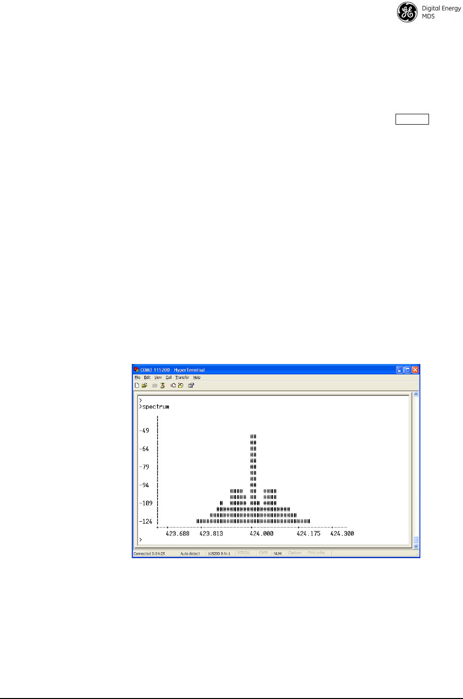
MDS 05-4670A01, Rev. E SD Series Reference Manual (x710 Mode) 37
The SNR is an indication of the received signal quality. A value of
10 dB represents a very poor signal. A value of 24 dB represents a very
good signal.
When the SNR command is used, it causes the
DIAG.
port to enter an
update mode, and the signal-to-noise ratio is updated and redisplayed
every 2 seconds. The SNR continuously updates until the key is
pressed.
SPECTRUM [xxx.xx]
Internal Spectrum
Analyzer Activates the built-in spectrum analyzer tool (see Figure 18) that can be shown
on a connected PC. This tool is helpful in diagnosing interference problems on
or near your channel frequency.
Access the spectrum analyzer by entering spectrum at the command prompt. A
display appears showing detected signals on your current channel.
Optionally, you can specify a frequency at the command prompt to view the
surrounding spectrum of that frequency. To do this, enter spectrum xxx.xx,
where xxx.xx is the frequency in MHz.
A typical spectrum analyzer display is shown in Figure 18. The display creates
a received signal strength indication (RSSI) vs. frequency plot for the fre-
quency and surrounding signals. By analyzing the display, you can determine
the presence of other signals near the transceiver’s operating frequency. This
information can be helpful in troubleshooting interference problems.
Invisible place holder
Figure 18. Internal Spectrum Analyzer Display
SQUELCH [AUTO, BYPASSED]
Squelch Operation
Set or show analog squelch bypass.
SREV
Software/Firmware
Revision Level
This command shows the software revision level of the transceiver firm-
ware.
ENTER

38 SD Series Reference Manual (x710 Mode) MDS 05-4670A01, Rev. E
STAT
Alarm Status
This command shows the current alarm status of the transceiver.
If no alarms exist, the message
NO ALARMS PRESENT
appears.
If an alarm does exist, a two-digit code (00–31) is displayed and the
alarm is identified as “Major” or “Minor.” A brief description of the
alarm code is also given.
If more than one alarm exists, the word
MORE
appears at the bottom of
the screen, and additional alarms are viewed by pressing the
key. Detailed descriptions of event codes are provided in Table 14 on
Page 41.
SWC [ON, OFF]
Switched Carrier
How you configure this command is based on whether or not the trans-
ceiver is listening to a continuously keyed master. If the master is not
continuously keyed, then the master is operating in switched carrier
mode and the transceiver’s SWC setting should be ON. If the master is
continuously keyed, the transceiver’s SWC setting should be OFF. For
B modem operation only. SWC should be OFF for A modems.
NOTE:
SWC
must be set to
ON
for switched carrier operation.
TFTP
TFTP Settings
Used to set/show all TFTP settings for upgrading the radio’s firmware
through the Ethernet port using TFTP transfer. The command can be
used in several different ways:
•
TFTP HOST [ipaddr]
sets the IP address of the TFTP server hosting
the firmware.
•
TFTP FILE [filename]
specifies the filename of the firmware to
downloaded.
•
TFTP GET
is used after the above commands to begin the TFTP
transfer.
•
TFTP STATUS
can be used to check on the progress of the down-
load.
TEMP
Internal
Temperature
This command shows the internal temperature of the transceiver in
degrees Celsius.
ENTER

MDS 05-4670A01, Rev. E SD Series Reference Manual (x710 Mode) 39
TOT [1-255, ON, OFF]
TX Timeout-Timer
This command sets or shows the transmitter Time-out Timer value
(1–255 seconds), as well as the timer status (
ON
or
OFF
). If the timer is
on, and the radio remains keyed for a longer duration than the
TOT
value,
the transmitter is automatically unkeyed.
When this happens, the radio must be commanded back to an unkeyed
state before a new keying command is accepted. The default timer value
is 30 seconds.
TX [xxx.xxxx]
TX Frequency
This command selects or shows the radio’s transmit frequency in MHz.
The frequency step size is 125 Hz.
If the customer frequency has not been programmed at the factory, a
default frequency will be programmed in the radio near the center of the
frequency band.
TXLEVEL [–20 to 0, AUTO]
TX Audio Input Level
The
TXLEVEL command
selects or shows the expected transmit audio
input level from an external modem. For more information, refer to the
detailed description of analog operation beginning on Page 46.
For optimum performance, set this parameter to match the external
modem level. For example
TXLEVEL –10
.
TXLEVEL AUTO
is also available
(default setting: –10 dBm).
UNIT [10000...65000]
Unit Address
The unit address is the radio’s unique identity for the network’s diag-
nostic activities. The unit responds to a request for a diagnostics code
broadcast by the Master Station to all Remotes in an MAS network, if
its unit address matches the number broadcast. The default number is
programmed by the factory to the last four digits of the radio’s serial
number.
UPTIME
Up Time
Displays time since last system reboot.
VERSION
Firmware Version
Displays package version information for each firmware image.

MDS 05-4670A01, Rev. E SD Series Reference Manual (x710 Mode) 40
7.0 TROUBLESHOOTING
Successful troubleshooting of the radio system is not difficult, but it
requires a logical approach. It is best to begin troubleshooting at the
master station, as the rest of the system depends on the master for
polling commands. If the master station has problems, the operation of
the entire network might be compromised.
It is good practice to start by checking the simple things. For proper
operation, all radios in the network must meet these basic requirements:
• Adequate and stable primary power. The radio contains an inter-
nal self-resetting fuse (5 A). Remove primary power to reset.
• Secure cable connections (RF, data and power).
• An efficient and properly aligned antenna system with a received
signal strength of at least –90 dBm (it is possible for a system to
operate with weaker signals, but reliability might be degraded).
• Proper programming of the transceiver’s operating parameters
(see Section 6.0, TRANSCEIVER MANAGEMENT on Page
21), especially the TX/RX frequency and MODEM type selec-
tions.
• The correct interface between the transceiver and the connected
data equipment (correct cable wiring, proper data format, timing,
etc.)
7.1 LED Indicators
The LED status indicators are an important troubleshooting tool and
should be checked whenever a problem is suspected. Table 10 on
Page 19 describes the function of each status LED.
7.2 Event Codes
When an alarm condition exists, the transceiver creates a code that can
be read on a connected PC. These codes can be very helpful in resolving
many system difficulties. Refer to Table 14 (Page 41) for a definition of
the event codes.
Checking for Alarms—STAT command
To check for alarms, enter
STAT
on the PC. If no alarms exist, the mes-
sage
NO ALARMS PRESENT
appears.
If an alarm does exist, a two-digit alarm code (01–31) is shown and the
event is identified as a Major or Minor Alarm. A brief description of the
alarm is also given.

MDS 05-4670A01, Rev. E SD Series Reference Manual (x710 Mode) 41
Major Alarms vs. Minor Alarms
Major Alarms (1-16)—report serious conditions that generally indicate
a hardware failure, or other abnormal condition that will prevent (or
seriously hamper) further operation of the transceiver. Major alarms
generally indicate the need for factory repair. Contact your Technical
Service representative for further assistance.
Minor Alarms (17-32)—report conditions that, under most circum-
stances, will not prevent transceiver operation. This includes out-of-tol-
erance conditions, baud rate mismatches, etc. The cause of these alarms
should be investigated and corrected to prevent system failure.
Event Code Definitions
Table 14 contains a listing of event codes that can be reported by the
transceiver. The codes shown are a subset of a larger pool of codes used
for various GE MDS products. For this reason, the table does not show
a sequential listing of all code numbers. Only the codes applicable to this
product are shown, and this list is subject to change with product revi-
sion.
Table 14. Event Codes
Event
Code
Event
Class Description
02 Major Frequency not programmed.
03 Major Authorization fault detected.
04 Major The RF synthesizer is reporting an out-of-lock
condition.
08 Major The system is reporting that it has not been
calibrated. Factory calibration is required for proper
radio operation.
09 Major DSP download fault.
12 Major Receiver time-out. No data received within the
specified receiver time-out time.
13 Major Transmitter time-out detected.
14 Major Alarm test.
16 Minor Unit address not programmed.
26 Minor The DC input voltage approaching an
out-of-tolerance condition. If the voltage is too far out
of tolerance, operation may fail.
29 Minor Output power not in valid range.
31 Minor The transceiver’s internal temperature is
approaching an out-of-tolerance condition. If the
temperature drifts outside of the recommended
operating range, system operation might fail.
37 Minor Unexpectedly executing APP 1.
38 Minor Unexpectedly executing APP 2.
39 Minor Boot error. Active image unknown.
42 Minor Reprogramming error.

42 SD Series Reference Manual (x710 Mode) MDS 05-4670A01, Rev. E
64 Minor A socket operation failed.
70 Minor AP not available.
41 Status Forced restart of Ethernet interface.
43 Status Reprogramming in progress.
44 Inform Firmware update successful.
45 Inform Reprogramming aborted.
46 Inform Remote rebooted.
Table 14. Event Codes (Continued)
Event
Code
Event
Class Description

MDS 05-4670A01, Rev. E SD Series Reference Manual (x710 Mode) 43
8.0 TECHNICAL REFERENCE
8.1 Technical Specifications
GENERAL
Frequency Range: SD1: 150-174 MHz
SD2: 216-235 MHz in one of the bands listed below:
Band A—216 to 220 MHz
Band B—220 to 222 MHz
Band C—220 to 235 MHz
Band D—216 to 220 MHz (50 kHz)
SD4: 300–512 MHz in one of 4 bands as follows:
Band A—350 to 400 MHz
Band B—400 to 450 MHz
Band C—450 to 512 MHz
Band D—300 to 360 MHz
SD9: 820–960 MHz
Band A—820 to 870 MHz
Band C—928 to 960 MHz
Band D—928 to 960 MHz (50 kHz)
Band E—880 to 915 MHz
Band F—880 to 915 MHz (50 kHz)
Band G—850 to 960 MHz/926 to 936 MHz TX Lo
Band H—850 to 960 MHz/926 to 936 MHz TX Hi
Specific frequency authorizations are dependent on the type-approval of the radio. Con-
sult the factory for details.
Bandwidths: SD1: 3.0, 6.25, 9.0, 12.5 kHz
SD2: 2.0, 3.0, 5.0, 6.25, 8.0, 9.0, 12.5, 15.0, 16.0,
25.0, 48.0, 50.0 kHz
SD4: 6.25, 11.0, 12.5, 20.0, 25.0 kHz
SD9: 4.0, 7.0, 10.0, 12.5, 16.0, 18.0, 25.0, 30.0,
50.0 kHz
NOTE: This information subject to change depending on specific
modem configuration. For emission designator information,
consult the FCC web site for latest “GE MDS” grants:
http://transition.fcc.gov/oet/ea/fccid/. Emission designators
are subject to change pending new FCC additions and
approvals.
RECEIVER
Maximum Usable Sensitivity: –112 dBm at 1x10
–6
BER (9600 BPS)
NOTE: Typical sensitivity rating at 9600 BPS. See Table 12 on Page 31 for detailed list-
ings by modem type.
TRANSMITTER
Carrier Power: 0.1 Watts to 5 Watts
Power Measurement Accuracy: +/- 1.5 dB
NOTE: RF output is limited to 2 watts for SD2 radios operating in Band B
(220-222 MHz).

MDS 05-4670A01, Rev. E SD Series Reference Manual (x710 Mode) 44
Duty Cycle: Variable up to 100%, dependent on application.
Continuous key operation not recommended.
Output Impedance: 50 Ω
:
DATA CHARACTERISTICS
Signaling Types: RS-232/485; DB-9 Female connector
Ethernet 10/100 Mbps; RJ-45F connector
COM2 Data Rates: 300–115200 bps, asynchronous
Data Latency: 11 ms to 12 ms typical (transparent)
PRIMARY POWER
Voltage: 10.0 to 30 Vdc (Negative ground only)
NOTE: Early SD4 models supported 10.5 to 16 Vdc power, not 10 to 30 Vdc. Check the
labeling above the power connector to confirm the operating range for your unit.
TX Supply Current (Typical): 2.5 A maximum @ 5 W RF Output
RX Supply Current (Typical):Operational—150 mA, Nominal
Sleep—<15 mA typical @ 13.8 Vdc
Fuse: 5 A, internal
ENVIRONMENTAL
Humidity: SD1: 95% at 70°C (158°F), non-condensing
SD2: 95% at 40°C (104°F), non-condensing
SD4: 95% at 70°C (158°F), non-condensing
SD9: 95% at 40°C (104°F), non-condensing
Temperature Range: –40 to 70°C (–40°F to 158°F)
Weight (nominal): 1.22 lbs. (0.55 kg)
Transceiver Dimensions: 6.5” long (16.51 cm)
4.625” wide (11.75 cm)
1.5” High (3.81 cm)
DIAGNOSTICS INTERFACE
Signaling Standard: RS-232 (COM1)
RS-232/RS-485 (COM2)
Connector: COM1—DB-9F
COM2—DB-9F
All specifications are subject to change without notice or obligation to
any party.
Product FCC ID IC ID
SD1 E5MDS-SD1 101D-SD1
SD2 E5MDS-SD2
E5MDS-SD2-1
101D-SD2
SD4 E5MDS-SD4
E5MDS-SD4-1
101D-SD4
101D-SD4-1
SD9 E5MDS-SD9
E5MDS-SD9-1
101D-SD9
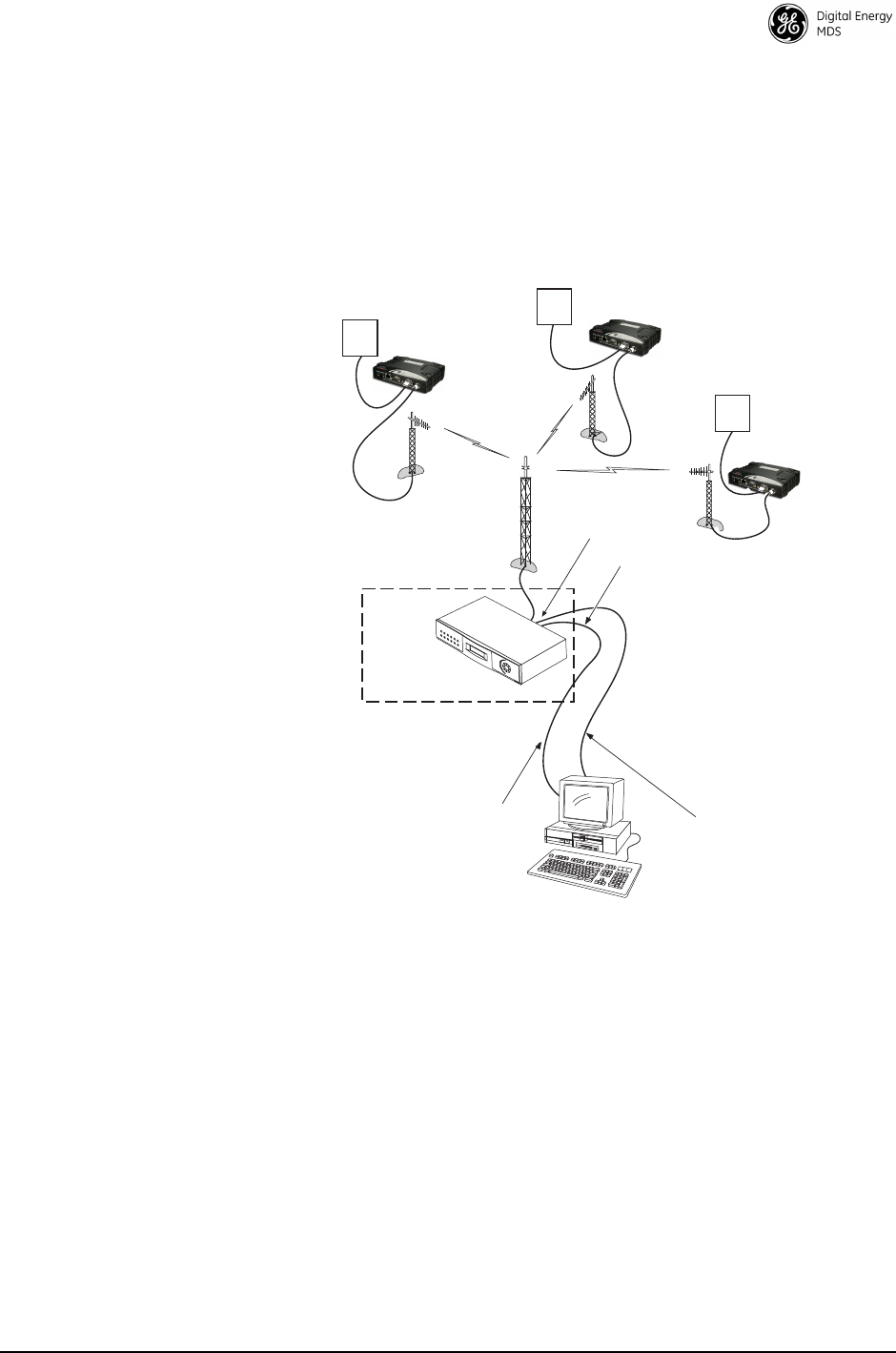
MDS 05-4670A01, Rev. E SD Series Reference Manual (x710 Mode) 45
8.2 Performing Network-Wide Remote Diagnostics
Diagnostics data from a remote radio can be obtained by connecting a
laptop or personal computer running compatible NMS software, such as
Element Manager or InSite,to any radio in the network. Figure 19 shows
a sample arrangement for performing network-wide remote diagnostics.
Invisible place holder
Figure 19. Network-Wide Remote Diagnostics Setup
If a PC is connected to any radio in the network, intrusive polling
(polling which briefly interrupts payload data transmission) can be per-
formed. To perform diagnostics without interrupting payload data trans-
mission, connect the PC to a radio defined as the “root” radio. A radio
is defined as a root radio using the
DTYPE ROOT
command locally, at the
radio.
A complete explanation of remote diagnostics can be found in the Net-
work-Wide Diagnostics System Handbook (Part No. 05-3467A01). See
the Handbook for more information about the basic diagnostic proce-
dures outlined below.
RTU
DIAGNOSTICS DATA
(TO InSite)
HOST COMPUTER
RTU
TO DIAGNOSTICS
PORT (DB-9)
TO DATA PORT
(DB-25)
MASTER STATION
DTYPE
ROOT
PAYLOAD DATA
(TO SCADA APPLICATION)
RTU
DTYPE
NODE
DTYPE
NODE
DTYPE
NODE

MDS 05-4670A01, Rev. E SD Series Reference Manual (x710 Mode) 46
1. Program one radio in the network as the root radio by entering the
DTYPE ROOT
command at the radio.
2. At the root radio, use the
DLINK ON
and
DLINK [baud rate]
commands
to configure the diagnostic link protocol on the Management Port.
3. Program all other radios in the network as nodes by entering the
DTYPE NODE
command at each radio.
4. Use the
DLINK ON
and
DLINK [baud rate]
commands to configure the
diagnostic link protocol on the Management Port of each node radio.
5. Connect same-site radios using a null-modem cable at the radios’
diagnostic ports.
6. Connect a PC running the management software to the root radio, or
to one of the nodes, using the radio’s
COM1
port. This PC can also
be the PC used to collect payload data, as shown in Figure 19.
7. Launch the diagnostic program at the PC.
8.3 User-Programmable I/O Functions - Pending
The transceiver can be internally configured to provide three user I/O
functions on the
COM1
and
COM2
data connectors. These signals are
commonly used for RTU resetting or for analog input monitoring. Once
the transceiver has been properly configured, these pins can be activated
through compatible NMS software, such as Element Manager or InSite.
The jumpering changes required to enable these functions are beyond
the scope of this manual. Consult the factory for further information on
enabling and using these I/O functions.
8.4 Analog Operation of the Transceiver
The transceiver is designed for full digital modulation, while offering
analog support to those systems that require it. Operation is compatible
with the MDS x710 family of products, but some SD radio-specific
command configuration and wiring might be necessary based on differ-
ences in SD hardware. This section provides important information for
using the radio in analog service.

MDS 05-4670A01, Rev. E SD Series Reference Manual (x710 Mode) 47
Physical Interface
The physical interface for analog operation utilizes pins on the radio’s
COM1
(management) connector. This connector is multiplexed with the
serial data lines used for software commands. The applicable pins of the
DB-9 are as follows:
•Pin 4—Transmit Audio
(-20 dBm to 0 dBm, as set by TXLEVEL command)
•Pin 5—Ground (negative supply potential)
•Pin 6—Push-to-Talk (3 V TTL, 5 V tolerant)
•Pin 8—Receive Audio
(-20 dBm to 0 dBm, as set by RXLEVEL command)
Operational Characteristics
Analog operation is available in two general modes: Analog-only or
Mixed Analog/Digital.
Analog-only operation is typically useful when interfacing with external
analog modems. Operation is selected by specifying
MODEM NONE
. In
this mode, RX and TX Audio are both always active; Carrier Detect
output and the
LINK
LED are asserted based on the receiver
unsquelching. Key sources automatically assume the use of TX Audio
as the input source. In analog-only mode, carrier detect is based on
squelch status.
Mixed analog/digital operation is useful for orderwire application, or for
analog systems that need to make use of GE MDS Network-Wide Diag-
nostics. Operation is enabled by selecting a digital modem type (for
example,
MODEM 9600
) and selecting
AUDIO ON
. In this mode RX Audio
is always active, but TX Audio only becomes active when the
Push-to-Talk (PTT, Pin 6) input signal is asserted. All other key sources
use digital modulation automatically. In this mode, Carrier Detect
output and the
LINK
LED are asserted based only on detection of digital
modulation.
The PTT “asserted” condition is defined by the
PTTSIG
command.
Entering
PTTSIG HI
configures the system for an active high Push-to-Talk
signal. Entering
PTTSIG LO
configures the system for an active low
Push-to-Talk signal. Entering
PTTSIG OFF
disables the Push-to-Talk
input—useful for RX audio monitoring of the channel when no TX
analog transmission is desired.
Analog operating characteristics (selected either by PTT assertion or the
MODEM NONE
command) vary based on channel type.
As a simple rule, SD characteristics associated with
MODEM NONE
are
driven by the last digital modem selection. For example, if
MODEM 9600
is selected followed by
MODEM NONE
, the characteristics for analog oper-
ation match the corresponding 12.5 kHz FCC/IC channel constraints. If

MDS 05-4670A01, Rev. E SD Series Reference Manual (x710 Mode) 48
MODEM 9600M
is selected followed by
MODEM NONE
, analog operation
conforms to the channel constraints for a 12.5 kHz ETSI-compliant
channel. Table 15 defines the relationship between digital modem selec-
tion and analog operation.
Modem transmission/reception characteristics are further qualified by
the
EMP
(emphasis) command. When
EMP ON
is entered, pre-emphasis is
applied on the transmitter and de-emphasis is applied on the receiver.
This setting is typically used in operation with voice radios. To disable
emphasis, select
EMP OFF
.
Audio signal levels are governed by the
RXLEVEL
and
TXLEVEL
com-
mands. Both commands support a range from -20 dBm to 0 dBm. For
RX operation, this means that a received signal at the peak deviation will
be scaled to the specified
RXLEVEL
. For TX operation, this means that a
transmit input signal of the specified
TXLEVEL
will translate into the
specified peak deviation for transmit. Note that
TXLEVEL
can also be set
to
AUTO
to automatically scale the input to the target deviation. Values
outside the expected range will cause clipping of the RF signal.
By default, built-in squelch thresholds automatically mute the receive
audio when a signal is not present. To bypass the squelch controls, enter
the command
SQUELCH BYPASSED
. To restore normal operation, enter
the command
SQUELCH AUTO
.
8.5 Upgrading the Radio’s Firmware
From time to time, GE MDS releases new firmware for its radio prod-
ucts to take advantage of engineering improvements or to add opera-
tional features. New firmware can be installed into existing radios in the
field, bringing them up to date with the firmware shipped with new
units.
Firmware files are available free of charge online at:
www.gemds.com/app/support/downloads
NOTE: Only firmware specifically designed for this model of radio
can be installed in the unit.
Table 15. Relationship Between Digital Modem Selection
and Analog Operation
Command Command Agency
Compliance
Analog
Chan. Size
Peak
Deviation
MODEM 19200 followed by... MODEM NONE FCC/IC 25.0KHz 5.0 kHz
MODEM 9600 followed by... MODEM NONE FCC/IC 12.5KHz 2.5 kHz
MODEM 9600M followed by... MODEM NONE ETSI 12.5KHz 2.0 kHz
MODEM 4800 followed by... MODEM NONE ETSI 12.5KHz 2.0 kHz
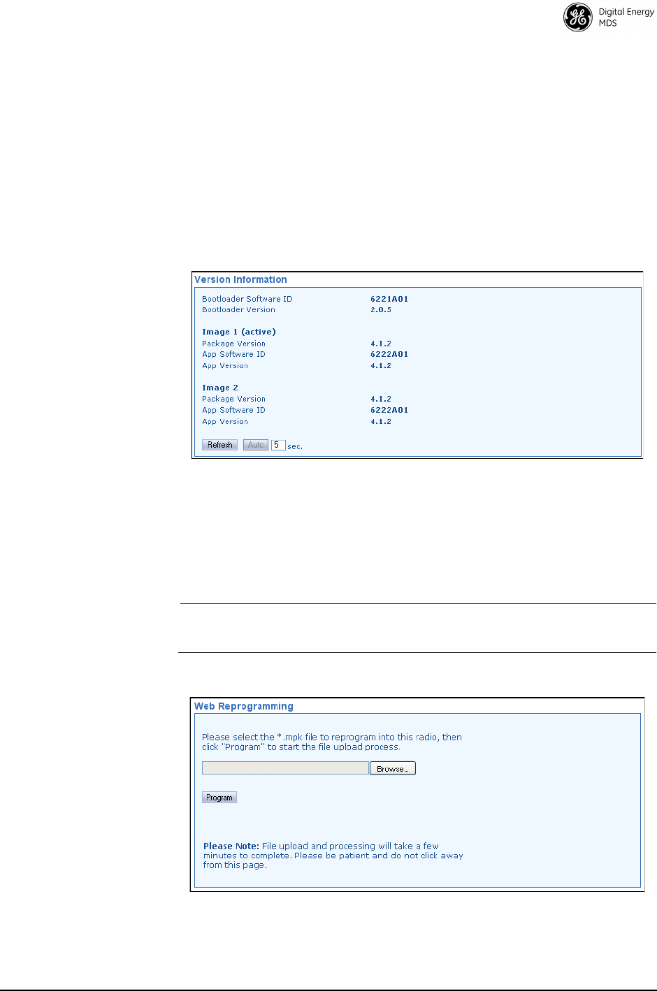
MDS 05-4670A01, Rev. E SD Series Reference Manual (x710 Mode) 49
Three methods can be used to load new firmware into the radio: Web
reprogramming, TFTP, and Serial Transfer. Firmware reprogram-
ming is best handled using the web-based Device Manager. Instructions
for these methods of transfer are given below, beginning with Web pro-
gramming.
Web Method
Determining Current
Firmware Version
This screen shows Bootloader version information and indicates which
firmware image (1 or 2) is currently active, as well as the firmware ver-
sion of each image. The information on this screen is read-only.
•
Refresh
—Clicking this button updates the displayed information
on demand.
•
Auto
—Initiates automatic updating of the information. A time (in
seconds) may be entered in the box provided, to specify how often
the display is updated.
NOTE: The latest firmware version for this product can be obtained at
www.gemds.com.
Web
Reprogramming
In the space provided, enter the
*.mpk
file to reprogram into this radio,
then click
Program
to start the file upload process. Do not click away
from this page until the upload has finished processing.
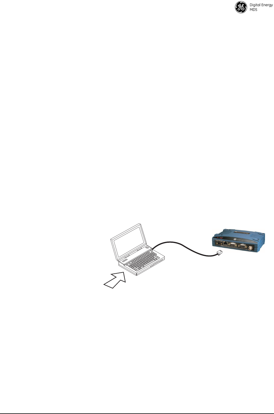
MDS 05-4670A01, Rev. E SD Series Reference Manual (x710 Mode) 50
TFTP Method
What You Will Need
To install firmware by TFTP, you will need:
1. A valid firmware file (see web address above). This will be a file
with a
.mpk
extension.
2. A PC equipped with Telnet, and a TFTP server running on the same
computer where the
.mpk
file is located (a Windows-based TFTP
server can be downloaded from the GE MDS Web site at:
www.gemds.com/Resources/TechnicalSupport
).
3. The IP address of the PC running the TFTP server. If you do not
know your computer’s IP address, use the
RUN
function from the
Start
menu and enter
cmd
to invoke the Windows Command Inter-
preter. At the
>
prompt, enter
ipconfig
to determine the address.
4. The IP address of the radio (the radio’s IP address can be found by
entering the
ipconfig
command with a serial command line session at
the radio).
Connecting the
Transceiver for
Firmware Upgrade
There are several alternatives to connecting the transceiver for firmware
upgrade. Figure 20 and Figure 21 show two common methods. It is
essential that all of the equipment be on the same subnet.
Invisible place holder
Figure 20. Firmware Upgrade Setup—Option 1
(TFTP Server and Firmware File Must Reside on Same Computer)
TO LAN
PORT
LOCAL PC WITH FIRMWARE FILE
TFTP
SERVER
& TELNET
TRANSCEIVER
E
T
H
E
R
N
E
T
C
A
B
L
E
INITIATE UPLOAD
FROM HERE
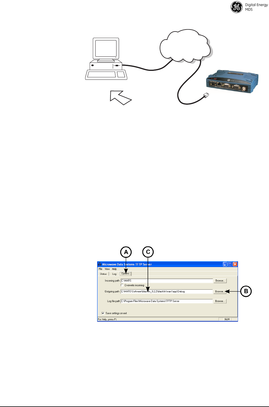
MDS 05-4670A01, Rev. E SD Series Reference Manual (x710 Mode) 51
Invisible place holder
Figure 21. Firmware Upgrade Setup—Option 2
(TFTP Server and Firmware File Must Reside on Same Computer)
Upgrade Procedure
(TFTP)
To load a new firmware file (
filename.mpk
) into the transceiver via TFTP,
follow these steps:
1. Connect an Ethernet cable between the radio’s
LAN
port and the PC
(refer to Figure 20 or Figure 21, as applicable). Verify that the
yellow LED on the radio’s
LAN
port lights and stays lit. This verifies
that the network is functioning.
2. Launch the TFTP server on the PC. If using the GE MDS TFTP
Server, click the
Options
tab (A in Figure 22 below) and modify the
Outgoing path
(B) using your browser to point to the folder where the
reprogramming package (
.mpk
file) is located. The path (C) will be
displayed once the operation is completed. Leave the application
running until reprogramming on the radio is complete.
Figure 22. TFTP Server Screen
(GE MDS Server shown)
3. Launch a Telnet session and connect to the radio using its pro-
grammed IP address (the radio and PC must be on the same IP net-
work to connect via Telnet).
TFTP
SERVER
ETHERNET
PORT
INITIATE UPLOAD
FROM HERE
REMOTE PC
W/FIRMWARE FILE
HUB/LAN/WAN/MAN
TCP/IP
TO LAN
PORT
IP ADDRESS: w.x.y.z
TRANSCEIVER

MDS 05-4670A01, Rev. E SD Series Reference Manual (x710 Mode) 52
4. Use the
tftp
command to configure the IP host and file to program.
For example:
>tftp host 10.4.147.63
>tftp file SDx-3_0_0
5. Enter
tftp get
to begin reprogramming. The file is loaded into the
radio’s inactive image. A series of progress messages display every
few seconds indicating the reprogramming status, followed by
Reprogramming Complete
when the process is finished.
6. Reboot the radio to the other image using the
boot other
command.
(At the
Are you sure?
message, make sure to enter
y
within 5 seconds
or the operation will be cancelled and you will be returned to the
>
prompt.) After
y
is pressed, the message
Rebooting to image...
will be
shown.
NOTE: Rebooting ends the current Telnet session. Reestablish a new
Telnet connection and proceed with the step below.
7. Enter the
SREV
command to verify the radio is running the new
application image. This completes the TFTP upgrade procedure.
NOTE: If a firmware installation fails, the radio is left with the original
active image intact, and the inactive image will be unusable.
Reprogramming should be attempted again.
Serial Transfer Method
Firmware upgrade via serial transfer is an alternative method which
takes longer to complete than TFTP, but accomplishes the same result.
This method is typically used when an Ethernet connection to a PC is
not available.
What You Will Need
To install firmware by serial transfer, you will need:
1. A valid firmware file (see web address given under “Upgrading the
Radio’s Firmware” on Page 48). This will be a file with an
.s28
extension.
2. A PC equipped with a terminal program, such as HyperTerminal
(included with many pre-Vista PCs).
Connecting the
Transceiver for
Firmware Upgrade
Connect a PC to the radio’s
COM1
Serial connector as shown in
Figure 23 to prepare for firmware upgrade.

MDS 05-4670A01, Rev. E SD Series Reference Manual (x710 Mode) 53
Invisible place holder
Figure 23. PC Connection to Transceiver (Serial)
Follow the steps below for serial transfer upgrade.
NOTE: Serial reprogramming takes several minutes at 115200 bps
baud rate (the recommended speed), but reprogramming is
possible at lower baud rates.
1. Launch a terminal session to the radio with the following
communications parameters: Baud 115200, 8 data bits, no parity,
one stop bit (8N1), XON/XOFF flow control, and VT100 emulation.
2. At the
>
prompt, enter
program
. At the
ARE YOU SURE?
prompt, enter
yes
.
3. At the
LOADER>
prompt, enter
erase
. The response
ERASED OK
is
returned.
4. At the
LOADER>
prompt, enter
program
. Do not type any more char-
acters at the prompt.
5. From the terminal program, quickly select
Transfer->Send Text File
and choose the correct file/file folder on the PC where the
.s28
firm-
ware file is located.
This process initiates the file transfer and causes the radio to repro-
gram the inactive image. When using HyperTerminal to perform
reprogramming, no status indication is available.
6. Programming is complete when
PROGRAMMED OK
appears at the
prompt. The active image has now been changed to the new
package. If this message is not seen, reprogramming did not com-
plete successfully and must be attempted again.
7. Reboot the unit by typing the
exit
command at the
LOADER>
prompt.
This completes the serial upgrade procedure. To verify that the radio
is running the newly loaded firmware image, enter the
srev
com-
mand after rebooting.
PC Running Terminal Session
Transceiver
DB-9M to COM1 Port

MDS 05-4670A01, Rev. E SD Series Reference Manual (x710 Mode) 54
NOTE: If a firmware installation fails, the radio is left with the original
active image intact, and the inactive image will be unusable.
Reprogramming should be attempted again.
Error Messages During File Transfers
It is possible to encounter errors during a file transfer. In most cases
errors can be quickly corrected by referring to Table 16.
Table 16. Common Errors During TFTP Transfer
Error Message Likely Cause/Corrective Action
Invalid File Type Indicates that the file is not a valid firmware
file. Locate proper file and re-load.
File not found Invalid or non-existent filename on TFTP
server
Invalid file path Invalid or non-existent file path to TFTP server
Timeout TFTP transfer time expired. Increase the
timeout value.
Bad CRC Cyclic Redundancy Check reporting a
corrupted file. Attempt to re-load, or use a
different file.
Version String Mismatch Invalid file detected. Attempt to re-load, or use
a different file.

MDS 05-4670A01, Rev. E SD Series Reference Manual (x710 Mode) 55
8.6 dBm-Watts-Volts Conversion Chart
Table 17 is provided as a convenience for determining the equivalent
wattage or voltage of an RF power expressed in dBm.
Table 17. dBm-Watts-Volts Conversion—for 50 Ohm Systems
dBm V Po
+53 100.0 200W
+50 70.7 100W
+49 64.0 80W
+48 58.0 64W
+47 50.0 50W
+46 44.5 40W
+45 40.0 32W
+44 32.5 25W
+43 32.0 20W
+42 28.0 16W
+41 26.2 12.5W
+40 22.5 10W
+39 20.0 8W
+38 18.0 6.4W
+37 16.0 5W
+36 14.1 4W
+35 12.5 3.2W
+34 11.5 2.5W
+33 10.0 2W
+32 9.0 1.6W
+31 8.0 1.25W
+30 7.10 1.0W
+29 6.40 800mW
+28 5.80 640mW
+27 5.00 500mW
+26 4.45 400mW
+25 4.00 320mW
+24 3.55 250mW
+23 3.20 200mW
+22 2.80 160mW
+21 2.52 125mW
+20 2.25 100mW
+19 2.00 80mW
+18 1.80 64mW
+17 1.60 50mW
+16 1.41 40mW
+15 1.25 32mW
+14 1.15 25mW
+13 1.00 20mW
+12 .90 16mW
+11 .80 12.5mW
+10 .71 10mW
+9 .64 8mW
+8 .58 6.4mW
+7 .500 5mW
+6 .445 4mW
+5 .400 3.2mW
+4 .355 2.5mW
+3 .320 2.0mW
+2 .280 1.6mW
+1 .252 1.25mW
dBm V Po
0 .225 1.0mW
-1 .200 .80mW
-2 .180 .64mW
-3 .160 .50mW
-4 .141 .40mW
-5 .125 .32mW
-6 .115 .25mW
-7 .100 .20mW
-8 .090 .16mW
-9 .080 .125mW
-10 .071 .10mW
-11 .064
-12 .058
-13 .050
-14 .045
-15 .040
-16 .0355
dBm mV Po
-17 31.5
-18 28.5
-19 25.1
-20 22.5 .01mW
-21 20.0
-22 17.9
-23 15.9
-24 14.1
-25 12.8
-26 11.5
-27 10.0
-28 8.9
-29 8.0
-30 7.1 .001mW
-31 6.25
-32 5.8
-33 5.0
-34 4.5
-35 4.0
-36 3.5
-37 3.2
-38 2.85
-39 2.5
-40 2.25 .1µW
-41 2.0
-42 1.8
-43 1.6
-44 1.4
-45 1.25
-46 1.18
-47 1.00
-48 0.90
dBm mV Po
-49 0.80
-50 0.71 .01µW
-51 0.64
-52 0.57
-53 0.50
-54 0.45
-55 0.40
-56 0.351
-57 0.32
-58 0.286
-59 0.251
-60 0.225 .001µW
-61 0.200
-62 0.180
-63 0.160
-64 0.141
dBm µV Po
-65 128
-66 115
-67 100
-68 90
-69 80
-70 71 .1nW
-71 65
-72 58
-73 50
-74 45
-75 40
-76 35
-77 32
-78 29
-79 25
-80 22.5 .01nW
-81 20.0
-82 18.0
-83 16.0
-84 11.1
-85 12.9
-86 11.5
-87 10.0
-88 9.0
-89 8.0
-90 7.1 .001nW
-91 6.1
-92 5.75
-93 5.0
-94 4.5
-95 4.0
-96 3.51
-97 3.2
dBm µV Po
-98 2.9
-99 2.51
-100 2.25 .1pW
-101 2.0
-102 1.8
-103 1.6
-104 1.41
-105 1.27
-106 1.18
dBm nV Po
-107 1000
-108 900
-109 800
-110 710 .01pW
-111 640
-112 580
-113 500
-114 450
-115 400
-116 355
-117 325
-118 285
-119 251
-120 225 .001pW
-121 200
-122 180
-123 160
-124 141
-125 128
-126 117
-127 100
-128 90
-129 80 .1ƒW
-130 71
-131 61
-132 58
-133 50
-134 45
-135 40
-136 35
-137 33
-138 29
-139 25
-140 23 .01ƒW

56 SD Series Reference Manual (x710 Mode) MDS 05-4670A01, Rev. E
9.0 GLOSSARY OF TERMS
If you are new to digital radio systems, some of the terms used in this
guide may be unfamiliar. The following glossary explains many of these
terms and will prove helpful in understanding the operation of the trans-
ceiver.
Active Messaging—This is a mode of diagnostic gathering that may
interrupt SCADA system polling communications (contrast with pas-
sive messaging). Active (or intrusive) messaging is much faster than
passive messaging because it is not dependent upon the RTU polling
cycle.
Antenna System Gain—A figure, normally expressed in dB, repre-
senting the power increase resulting from the use of a gain-type antenna.
System losses (from the feedline and coaxial connectors, for example)
are subtracted from this figure to calculate the total antenna system gain.
Bit—The smallest unit of digital data, often represented by a one or a
zero. Eight bits (plus start, stop, and parity bits) usually comprise a byte.
Bits-per-second—See BPS.
BPS—Bits-per-second. A measure of the information transfer rate of
digital data across a communication channel.
Byte—A string of digital data usually made up of eight data bits and
start, stop and parity bits.
Decibel (dB)—A measure computed from the ratio between two signal
levels. Frequently used to express the gain (or loss) of a system.
Data Circuit-terminating Equipment—See DCE.
Data Communications Equipment—See DCE.
Data Terminal Equipment—See DTE.
dBi—Decibels referenced to an “ideal” isotropic radiator in free space.
Frequently used to express antenna gain.
dBm—Decibels referenced to one milliwatt. An absolute unit used to
measure signal power, as in transmitter power output, or received signal
strength.
DCE—Data Circuit-terminating Equipment (or Data Communications
Equipment). In data communications terminology, this is the “modem”
side of a computer-to-modem connection. The transceiver described in
this manual is hardwired as a DCE device.
Digital Signal Processing—See DSP.

MDS 05-4670A01, Rev. E SD Series Reference Manual (x710 Mode) 57
DSP—Digital Signal Processing. The transceiver’s DSP is the core
operating unit of the transceiver through which nearly all functions
depend.
DTE—Data Terminal Equipment. A device that provides data in the
form of digital signals at its output. Connects to the DCE device.
Equalization—The process of reducing the effects of amplitude, fre-
quency or phase distortion with compensating networks.
Fade Margin—The greatest tolerable reduction in average received
signal strength to be expected under most conditions. Provides an allow-
ance for reduced signal strength due to multipath, fading, slight antenna
movement or changing atmospheric losses. A fade margin of 20 to 30
dB is usually sufficient in most systems.
Frame—A segment of data that adheres to a specific data protocol and
contains definite start and end points. It provides a method of synchro-
nizing transmissions.
Hardware Flow Control—A transceiver feature used to prevent data
buffer overruns when handling high-speed data from the RTU or PLC.
When the buffer approaches overflow, the radio drops the clear-to-send
(CTS) line, which instructs the RTU or PLC to delay further transmis-
sion until CTS again returns to the high state.
Host Computer—The computer installed at the master station site,
which controls the collection of data from one or more remote sites.
Intrusive Diagnostics—A mode of remote diagnostics that queries and
commands radios in a network with an impact on the delivery of the
system “payload” data. See Active messaging.
Latency—The delay (usually expressed in milliseconds) between when
data is applied to TXD (Pin 2) at one radio, until it appears at RXD
(Pin 3) at the other radio.
MAS—Multiple Address System. A radio system where a central
master station communicates with several remote stations for the pur-
pose of gathering telemetry data.
Master (Station)—Radio which is connected to the host computer. It is
the point at which polling enters the network.
Multiple Address System—See MAS.
Network-Wide Diagnostics—An advanced method of controlling and
interrogating GE MDS radios in a radio network.
Non-intrusive diagnostics—See Passive messaging.

58 SD Series Reference Manual (x710 Mode) MDS 05-4670A01, Rev. E
Passive messaging—This is a mode of diagnostic gathering that does
not interrupt SCADA system polling communications. Diagnostic data
is collected non-intrusively over a period of time; polling messages are
carried with SCADA system data (contrast with active messaging).
Payload data—This is the application’s user communication data
which is sent over the radio network.
Point-Multipoint System—A radio communications network or
system designed with a central control station that exchanges data with
a number of remote locations equipped with terminal equipment.
Poll—A request for data issued from the host computer (or master PLC)
to a remote radio.
PLC—Programmable Logic Controller. A dedicated microprocessor
configured for a specific application with discrete inputs and outputs. It
can serve as a host or as an RTU.
Programmable Logic Controller—See PLC.
Remote (Station)—A radio in a network that communicates with an
associated master station.
Remote Terminal Unit—See RTU.
Redundant Operation—A station arrangement where two transceivers
and two power supplies are available for operation, with automatic
switch-over in case of a failure.
RTU—Remote Terminal Unit. A data collection device installed at a
remote radio site. An internal RTU simulator is provided with the trans-
ceiver to isolate faults to either the external RTU or the radio.
SCADA—Supervisory Control And Data Acquisition. An overall term
for the functions commonly provided through an MAS radio system.
Standing Wave Ratio—See SWR.
Supervisory Control And Data Acquisition—See SCADA.
SWR—Standing Wave Ratio. A parameter related to the ratio between
forward transmitter power and the reflected power from the antenna
system. As a general guideline, reflected power should not exceed 10%
of the forward power (≈ 2:1 SWR).

MDS 05-4670A01, Rev. E SD Series Reference Manual (x710 Mode) 59
NOTES

60 SD Series Reference Manual (x710 Mode) MDS 05-4670A01, Rev. E

MDS 05-4670A01, Rev. E SD Series Reference Manual (x710 Mode) I-1
A
Active messaging (defined) 56
Alarms
alarm code definitions 41
major vs. minor 41
using STAT command to display 38
AMASK command 25
Antenna
installation 18
system gain, defined 56
Yagi, illustrated 11
Antennas 11
Applications 6
Multiple Address Systems (MAS) 6
point-to-multipoint system 6
point-to-point system 7
ASENSE command 25
B
BAUD command 26
Baud rate
setting for RJ-11 DIAG port (DLINK command) 28, 46
Bit, defined 56
Bits-per-second. See BPS 56
BPS (bits-per-second), defined 56
BUFF command 26
Byte, defined 56
C
Cable
maximum length, recommended 16, 17
Cable, loss due to length of coaxial at 960 MHz 12, 15
Cautions
use attenuation between all units in test setup 45
CKEY command 27
Command summary, table 21
Commands
AK (authorization key) 25
AMASK (set/display alarm triggers) 25
ASENSE (set alarm output state) 25
BAUD (set/display rate, encoding) 26
BUFF (set/display data handling mode) 26
CKEY (enable/disable continuous keying) 27
CTS (set/display CTS line response timer) 27
DATAKEY (enable/disable transmitter keying by radio) 28
descriptions 21–39
DEVICE (set/display radio behavior) 28
DKEY (deactivate transmitter after KEY command) 28
DLINK (enable/disable network-wide diagnostics) 28
DTYPE (set radio to root or node for diagnostics) 29
DUMP (display all programmed settings) 29
entering on Hand-Held Terminal (HHT) 21
INIT (reinitialize radio to factory defaults) 30
INIT xx10 (restore standard transceiver defaults) 30
INIT xx20 (configure radio for use with P-20 chassis) 30
KEY (activate transmitter) 31
MODEL (display radio model number code) 31
MODEM (set modem speed) 31
OWM (set/display owner’s message) 33
OWN (set/display owner’s name) 33
PTT (set/display key-up delay) 34
PWR (set/display RF forward output power) 34
RSSI (display RSSI) 34
RTU (enable/disable internal RTU) 35
RX (set/display receive frequency) 35
RXTOT (set/display receive time-out timer value) 36, 39
SCD (set/display soft-carrier dekey delay) 36
SER (display radio serial number 36
SHOW (display DC voltage, data port, RF power) 36
SNR (display signal-to-noise ratio) 36
SREV (display software revision level) 37
STAT (display current alarm status) 38
SWC (switched carrier) 38
TEMP (display internal temperature) 38
TOT (set/display time-out value and timer status) 39
TX (set/display transmit frequency) 39
Conversions, dBm-Watts-Volts 55
CTS command 27
D
Data Circuit-terminating Equipment—See DCE 56
Data Communications Equipment—See DCE. 56
Data interface
display active connector port 36
Data Terminal Equipment—See DTE 56
DATAKEY command 28
dB. See Decibel 56
dBi, defined 56
dBm, defined 56
DCE (Data Circuit-terminating Equipment), defined 56
Decibel (dB), defined 56
Description, product 3, 4
DEVICE command 28
Diagnostics
interface specifications 44
network-wide, performing 44, 46
PC software used for 48
using InSite software for network-wide 45
Digital Signal Processing—See DSP. 56
DIN Rail Mounting Bracket 6
Display
alarm status (STAT command) 38
alarm triggers (AMASK command) 25
all programmed settings (DUMP command) 29
baud rate and encoding (BAUD command) 26
connector port, active (SHOW command) 36
CTS line response timer (CTS command) 27
data handling mode (BUFF command) 26
DC voltage (SHOW command) 36
key-up delay (PTT command) 34
model number code (MODEL command) 31
owner’s message (OWM command) 33
owner’s name (OWN command) 33
radio behavior (DEVICE command) 28
radio serial number (SER command) 36
receive frequency (RX command) 35
receive time-out timer value (RXTOT command) 36, 39
RF forward output power (PWR command) 34
RF output (SHOW command) 36
RSSI (RSSI command) 34
signal-to-noise ratio (SNR command) 36
soft-carrier dekey delay (SCD command) 36
software revision level (SREV command) 37
temperature, internal (TEMP command) 38
time-out value and timer status (TOT command) 39
transmit frequency (TX command) 39
DKEY command 28
DLINK command 28
use of 46
Downloading new software 48
DSP (Digital Signal Processing), defined 57

MDS 05-4670A01, Rev. E SD Series Reference Manual (x710 Mode) I-2
DTE (Data Terminal Equipment), defined 57
DTYPE command 29
use of 46
DUMP command 29
E
Enable/disable
continuous keying (CKEY command) 27
internal RTU (RTU command) 35
network-wide diagnostics (DLINK command) 28
network-wide diagnostics, procedures 46
Environment specifications 44
Equalization, defined 57
F
Fade margin, defined 57
Feedlines 11
firmware
installing 50, 52
Frame, defined 57
Frequency
setting. See TX and RX commands
G
Glossary 56
H
Half-duplex 7
switched carrier operation 8
Hand-Held Terminal (HHT)
entering commands 21
Hardware flow control, defined 57
Host computer, defined 57
I
IEC
61000-4-5 Annex A 18
IEC61850-3 18
Illustrations
antenna, Yagi 11
MAS network 7
network-wide diagnostics 45
point-to-point link 7
remote station arrangement 9
INIT command 30
INIT xx10 command 30
INIT xx20 command 30
InSite software
using to perform remote diagnostics 45
Installation
antenna 18
power 18
power connection 12, 13
Intrusive diagnostics (defined) 57
K
KEY command 31
Keying
continuously keyed versus switched carrier operation 8
continuously keyed, defined 8
on data (DKEY command) 28
switched carrier, defined 8
L
Latency, defined 57
LEDs
PWR 19
status indicators, illustrated 19
Loss. See Signal
M
MAS (Multiple Address System) 6
defined 57
illustration 7
Master Station
defined 57
keying behavior 8
MODEL command 31
Model number codes 6
displaying (MODEL command) 31
MODEM command 31
Modem, set speed. See MODEM command
Mounting instructions 9
Multiple Address System—See MAS. 57
N
Network-wide diagnostics
active messaging, defined 56
defined 57
enable/disable (DLINK command) 28
enable/disable internal RTU (RTU command) 35
illustrated 45
intrusive diagnostics, defined 57
passive messaging (defined) 58
procedures 44, 46
set radio to root or node (DTYPE command) 29
Non-intrusive diagnostics—See Passive messaging. 57
O
Operation 21
environment specifications for 44
OWM command 33
OWN command 33
Owner’s message, set/display. See OWM command
Owner’s name, set/display. See OWN command
P
Passive messaging (defined) 58
Payload data (defined) 58
PLC (Programmable Logic Controller), defined 58
Point-to-multipoint
defined 58
system 6
Point-to-point
link, illustrated 7
system 7
Poll, defined 58
Power
connection 12, 13
display DC voltage (SHOW command) 36
display RF output (SHOW command) 36
installing 18
LED status indicator (PWR LED) 19
RF, chart for converting dBm-Watts-Volts 55
specifications 44
Procedures
checking for alarms (STAT command) 40
downloading new software 48
entering commands using the Hand-Held Terminal
(HHT) 21

MDS 05-4670A01, Rev. E SD Series Reference Manual (x710 Mode) I-3
mounting the transceiver 9
network-wide diagnostics 44, 46
operation 21
troubleshooting 40–41
Product
description 3, 4
display model number code (MODEL command) 31
display radio serial number (SER command) 36
model number codes 6
Programming radio as root or node 46
Programming, transceiver 21–39
protocol
TFTP 50, 52
PTT
command 34
PWR
command 34
LED 19
R
Radio
Configuration Software 48
serial number, displaying (SER command) 36
Receiver
specifications 44
system specifications 43
Redundant operation, defined 58
Remote
Station, defined 58
Station, illustrated 9
Resetting
transceiver (INIT command) 30
Revision level
display software (SREV command) 37
RSSI
command 34
RTU
command 35
RTU (Remote Terminal Unit)
defined 58
RX command 35
RXTOT command 36, 39
S
SCADA (Supervisory Control And Data Acquisition),
defined 58
SCD command 36
SER command 36
Set
alarm output state (ASENSE command) 25
alarm triggers (AMASK command) 25
receive time-out timer value (RXTOT command) 36, 39
SHOW command 36
Signal
loss due to coaxial cable length at 960 MHz, table 12, 15
Simplex 7
single-frequency operation 8
special case of switched carrier operation 8
Sleep mode
shown by PWR LED status indicator 19
SNR command 36
Software
diagnostics and control used from PC 48
display revision level 37
upgrading 48
Specifications
diagnostics interface 44
environment 44
power 44
receiver 44
receiver system 43
transmitter 43
transmitter system 43
SREV command 37
Standing Wave Ratio—See SWR. 58
STAT command 38
Supervisory Control And Data Acquisition—See SCADA. 58
surge suppression 18
SWR (Standing Wave Radio), defined 58
T
Tables
alarm code definitions 41
command summary 21
conversions, dBm-Watts-Volts 55
LED status indicators 19
length vs. loss in coaxial cables at 960 MHz 12, 15
Technical reference 43–55
TEMP command 38
Temperature, displaying internal (TEMP command) 38
Timer, set/display time-out value and status (TOT
command) 39
TOT command 39
Transceiver
applications 6
diagnostics using PC software 48
mounting 18
mounting instructions 9
programming 21–39
upgrading software 48
Transmitter
specifications 43
system specifications 43
Troubleshooting 40–41
performing network-wide diagnostics 44, 46
STAT command (Status) 40
using PC software for 48
TX command 39

MDS 05-4670A01, Rev. E SD Series Reference Manual (x710 Mode) I-4

IN CASE OF DIFFICULTY...
GE MDS products are designed for long life and trouble-free operation. However, this equipment, as with
all electronic equipment, may have an occasional component failure. The following information will assist
you in the event that servicing becomes necessary.
TECHNICAL ASSISTANCE
Technical assistance for GE MDS products is available from our Technical Support Department during
business hours (8:30 A.M.–6:00 P.M. Eastern Time). When calling, please give the complete model
number of the radio, along with a description of the trouble/symptom(s) that you are experiencing. In many
cases, problems can be resolved over the telephone, without the need for returning the unit to the factory.
Please use one of the following means for product assistance:
Phone: 585 241-5510 E-Mail: gemds.techsupport@ge.com
FAX: 585 242-8369 Web: www.gemds.com
FACTORY SERVICE
Component level repair of this equipment is not recommended in the field. Many components are installed
using surface mount technology, which requires specialized training and equipment for proper servicing.
For this reason, the equipment should be returned to the factory for any PC board repairs. The factory is
best equipped to diagnose, repair and align your radio to its proper operating specifications.
If return of the equipment is necessary, you must obtain a Service Request Order (SRO) number. This
number helps expedite the repair so that the equipment can be repaired and returned to you as quickly as
possible. Please be sure to include the SRO number on the outside of the shipping box, and on any corre-
spondence relating to the repair. No equipment will be accepted for repair without an SRO number.
SRO numbers are issued online at www.gedigitalenergy.com/Communications.htm. On the left side of the
page, click “Login to my MDS” and once logged in, click “Service Request Order”. Your number will be
issued immediately after the required information is entered. Please be sure to have the model number(s),
serial number(s), detailed reason for return, “ship to” address, “bill to” address, and contact name, phone
number, and fax number available when requesting an SRO number. A purchase order number or pre-
payment will be required for any units that are out of warranty, or for product conversion.
If you prefer, you may contact our Product Services department to obtain an SRO number:
Phone Number: 585-241-5540
Fax Number: 585-242-8400
E-mail Address: gemds.productservices@ge.com
The radio must be properly packed for return to the factory. The original shipping container and packaging
materials should be used whenever possible. All factory returns should be addressed to:
GE MDS, LLC
Product Services Department
(SRO No. XXXX)
175 Science Parkway
Rochester, NY 14620 USA
When repairs have been completed, the equipment will be returned to you by the same shipping method
used to send it to the factory. Please specify if you wish to make different shipping arrangements. To
inquire about an in-process repair, you may contact our Product Services Group using the telephone, Fax,
or E-mail information given above.

GE MDS, LLC
Rochester, NY 14620
Telephone: +1 585 242-9600
FAX: +1 585 242-9620
www.gemds.com
175 Science Parkway