GE MDS DS-SDM9 MDS SDM9 Licensed Spectrum Module User Manual SDM9 Operation Manualx
GE MDS LLC MDS SDM9 Licensed Spectrum Module SDM9 Operation Manualx
UserManual.wiki
>
GE MDS
>
DS SDM9 User Manual
User Manual
Navigation menu
Upload a User Manual
Namespaces
Wiki Guide
HTML
PDF
Info
Views
User Manual
Discussion / Help
Navigation
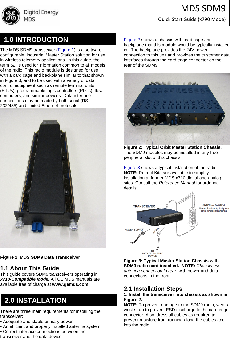
![MDSSDM9QuickStartGuide(x790Mode)2. Install the antenna and feedline. The antenna used with the radio must be designed to operate in the radio’s frequency band, and be mounted in a location providing a clear path to the associated station(s). At Remote sites, aim directional antennas toward the Master Station. Low loss coaxial feedline should be used and it should be kept as short as possible. 3. Connect the data equipment. Connection may be made to the COM port using Serial protocols (RS-232/RS-485). RJ45 to DB9/DB25 adapters may be required depending on physical data port connector type used on the data telemetry device to be attached as shown in Figure 3. 4. Connect primary power to the Orbit Chassis. Input power must within the ranges specified for the power supply module installed in the Orbit chassis: 12VDC, 24VDC, 48VDC, 125VDC, or 90-264VAC. These supplies all convert incoming power to +24V for SDM9 Module operation. 5. Set the radio’s configuration. Connect a PC to the radio’s COM1 and COM2 ports as shown in Figure 4. A straight-thru cable may be used for this connection with an RJ45 to DB9 adapter. NOTE: Consult your System Administrator if you are unsure of the settings required for your network. Figure 4. Setup for PC Configuration 2.1.1 Software Configuration There are two methods for communicating with the radio for configuration and management: Serial (COM1, COM2 RJ45 connector) and Telnet (ETHERNET RJ-45 connector). Both present identical functionality and use the same commands, but the method to configure access is different for each. NOTE: Transmitter and Receiver configuration are handled through separate DSP devices, thus two serial ports or two Telnet sessions will be required to handle configuration of these two functions. The focus here is on Serial access, but Telnet may be used by following these additional points, which replace Steps 1 and 2 below: • For Telnet, connect to the radio with a PC that is on the same IP network as the transceiver. Launch a Telnet program, and connect to the radio using its programmed IP address for the Transmitter and Receiver. • The default IP address of the Transmitter configuration is 192.168.1.1. The default IP address of the Receiver configuration is 192.168.1.2. If you do not know the IP address of the radio, use the serial configuration steps below to view the address with the IPCONFIG command. 1. With a PC connected to the COM1 serial port, launch a terminal program, such as HyperTerminal (included withmost pre-Windows7®-based PCs) and set the following parameters: 8 bits, no parity, one stop bit (8N1), flow control disabled, VT100 emulation. The COM port automatically finds the connected baud rate (within 1200–115200 bps). 2. Press the ESCAPE key followed by a series of ENTER keypresses (at 1/2 second intervals) until the > prompt appears. The radio is now ready to accept commands. 3. Set/verify the RX (receive) and TX (transmit) frequencies. To set the receive frequency, enter RX followed by the correct frequency in MHz (xxx.xxxxx). Press ENTER . To set the transmit frequency, enter TX followed by the correct frequency in MHz (xxx.xxxxx). Press ENTER. 4. The factory default modem settings support 9600 bps transmission in a 12.5 kHz bandwidth channel. Many other options are available. The current setting may be viewed using the MODEM command. Use MODEM [xxxx] if changes are required. When finished with the steps above, review the other configuration options to determine if other settings are required for your system. Table 3 lists key software commands for the radio. 2.2 Initial Checkout In-service operation is completely automatic. The only operator actions required are to apply DC power and observe the LEDS for proper indications. Table 1 on the following page summarizes the radio’s LED functions.](https://usermanual.wiki/GE-MDS/DS-SDM9/User-Guide-2204477-Page-2.png)
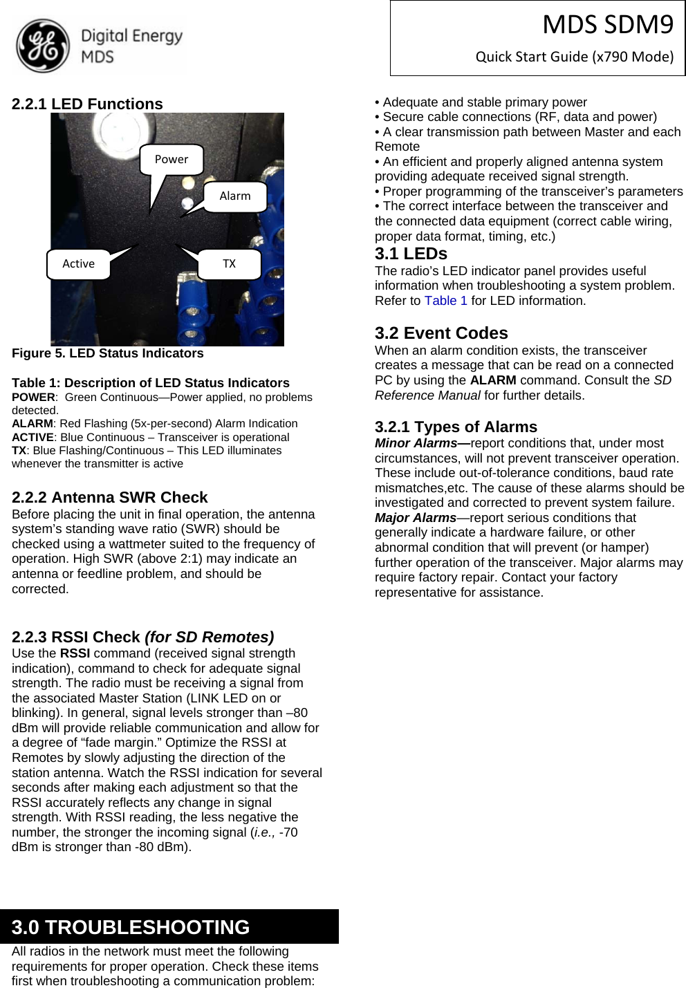
![MDSSDM9QuickStartGuide(x790Mode) Table 3 lists key software commands for the transceiver. Detailed descriptions are provided in the SD Reference Manual. Commands can typically be used in two ways: 1. The basic command (shown first) may be entered alone to issue a query or execute a simple command. 2. The basic command may be appended with additional arguments (shown in brackets, if applicable) to further define a setting. RF Exposure Notice The radio equipment described in this guide emits radio frequency energy. Although the power level is low, the concentrated energy from a directional antenna may pose a health hazard. Do not allow people to come closer than 1.50 meters to the front of the antenna when the transmitter is operating with a 7 dBd (9.15 dBi) gain antenna. Use of higher gain antennas means increasing the distance accordingly. FCC Part 15 Notice Operation of this device subject to the following two conditions: (1) this device may not cause harmful interference, and (2) (2) this device must accept any interference received, including interference that may cause undesired operation. Any unauthorized modification or changes to this device without the express approval of the manufacturer may void the user’s authority to operate this device. Furthermore, this device is intended to be used only when installed in accordance with the instructions outlined in this guide. Failure to comply with these instructions may void the user’s authority to operate this device. Table 3: Key Software Commands Command Function ALARM Read current operating condition of the radio. BAUD [xxxxx abc] Set/display the data rate and control bits. BUFF [ON, OFF] Enables or disables the internal radio data buffer. CTS [0-255] Set/display the Clear-to-Send delay in seconds. DEV Display modem control deviation. DEVICE [DCE, CTS KEY] Set/display device mode. DKEY Dekey the radio (transmitter OFF). This is generally used as a radio test command. DUMP Display all programmable settings. HELP Shows available commands. KEY Key the radio (transmitter ON). This is generally used as a radio test command. MODEM [xxxx] Set the modem characteristics of the radio. PORT [RS232, RS485] Set/display COM2 data port interface settings. PTT [0-255] Set/display the Push-to-Talk delay in milliseconds. PWR [20-40] Set/display the transmit power setting. RSSI Display the Received Signal Strength Indication. RTU [ON/OFF/0-80] Re-enables or disables the radio’s internal RTU simulator and sets the RTU address. RX [xxx.xxxx] Set/display the receive frequency. RXLEVEL [-20 to 0] Set/display the receive audio input level. SCD [0-255] Set/display the Soft-Carrier Dekey delay in milliseconds. SHOW [DC, PWR] Display the DC voltages and transmit power level. SNR Signal-to-Noise Ratio, expressed in dB SPECTRUM [xxx.xx] Display the transceiver’s built-in spectrum analyzer, where xxx.xx denotes center frequency. STAT Display radio status and alarms. TEMP Display the internal temperature of the radio in degrees C. TOT [1-255, ON, OFF] Set/display the Time-out Timer delay in seconds. TX [xxx.xxxx] Set/display the transmit frequency. TXLEVEL [-20 to 0, AUTO] Set/display the transmit audio input level. UNIT [10000...65000] Set/display the transceiver’s unit address. 4.0 COMMAND OVERVIEW](https://usermanual.wiki/GE-MDS/DS-SDM9/User-Guide-2204477-Page-4.png)