GE MDS DS9710N MDS Remote Data Transceiver User Manual 3305B x710A C Body
GE MDS LLC MDS Remote Data Transceiver 3305B x710A C Body
GE MDS >
Users Manual Revised
Installation and Operation Guide
MDS 05-3305A01, Rev. B
SEPTEMBER 2000
400 MHz/900 MHz
Remote Data Transceiver
MDS 4710/9710 Series
(Including MDS 4710A/C and MDS 9710 A/C)
QUICK START GUIDE
Below are the basic steps for installing the transceiver. Detailed instructions are given in “INSTALLA-
TION” on page 9 of this guide.
1. Install and connect the antenna system to the radio
• Use good quality, low loss coaxial cable. Keep the feedline as short as possible.
• Preset directional antennas in the direction of desired transmission.
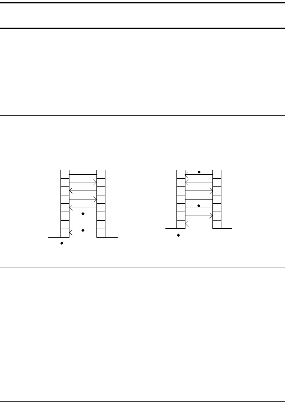
2. Connect the data equipment to the radio’s INTERFACE connector
• Connection to the radio must be made with a DB-25 Male connector. Connections for typical sys-
tems are shown below.
• Connect only the required pins. Do not use a straight-through RS-232 cable with all pins wired.
• Verify the data equipment is configured as DTE. (By default, the radio is configured as DCE.)
3. Apply DC power to the radio (10.5–16 Vdc @ 2.5 A minimum)
• Observe proper polarity. The red wire is the positive lead; the black is negative.
4. Set the radio’s basic configuration with a Hand-Held Terminal (HHT)
• Set the transmit frequency (
TX xxx.xxxx
).
• Set the receive frequency (
RX xxx.xxxx
).
• Set the baud rate/data interface parameters as follows. Use the
BAUD xxxxx abc
command, where
xxxxx
equals the data speed (110–38400 bps) and
abc
equals the communication parameters as
follows:
a
= Data bits (7 or 8)
b
= Parity (N for None, O for Odd, E for Even
c
= Stop bits (1 or 2)
(Example:
BAUD 9600 8N1
)
NOTE: 7N1, 8E2 and 8O2 are invalid parameters and are not supported by the transceiver.
5. Verify proper operation by observing the LED display
• Refer to Table 5 on page 16 for a description of the status LEDs.
• Refine directional antenna headings for maximum receive signal strength using the
RSSI
command.
DB-25 DB-25
TRANSCEIVER
(DCE)
2
3
2
3
RTU
(DTE)
4
5
20
6DSR DSR
6
TXD
RXD
GND
RTS
CTS
TXD
RXD
GND
4
CTS
5
RTS
DB-9 DB-25
DB-9 to DB-25 ExampleDB-25 to DB-25 Example
11
4
5
TRANSCEIVER
(DCE)
2
3
3
2
RTU
(DTE)
5
20
7
RXD
TXD
DCD
GN
D
DSR
RTS
RXD
TXD
DCD
GN
D
As required for application
5
18
7
6
CTS
DSR
RTS
CTS8
6
4
5
77
GND GND
8 8
DCD DCD
As required for application

MDS 05-3305A01, Rev. B MDS 4710/9710 I/O Guide i
TABLE OF CONTENTS
1.0 GENERAL.................................................................................... 1
1.1 Introduction ......................................................................................1
1.2 Applications ......................................................................................2
Point-to-Multipoint, Multiple Address Systems (MAS) ........................2
Point-to-Point System .........................................................................3
Continuously Keyed versus Switched Carrier Operation....................3
Single Frequency (Simplex) Operation...............................................3
1.3 Model Number Codes ......................................................................3
1.4 Accessories ......................................................................................4
2.0 GLOSSARY OF TERMS.............................................................. 6
3.0 INSTALLATION............................................................................ 9
3.1 Installation Steps ..............................................................................9
3.2 Transceiver Mounting .....................................................................11
3.3 Antennas and Feedlines ................................................................11
Feedlines ..........................................................................................12
3.4 Power Connection ..........................................................................13
3.5 Data Interface Connections ............................................................13
3.6 Using the Radio’s Sleep Mode .......................................................13
System Example...............................................................................13
4.0 OPERATION.............................................................................. 15
4.1 LED Indicators ................................................................................16
4.2 RSSI Measurement ........................................................................16
5.0 TRANSCEIVER PROGRAMMING ............................................ 17
5.1 Hand-Held Terminal Connection & Startup ....................................17
5.2 Hand-Held Terminal Setup .............................................................18
5.3 Keyboard Commands .....................................................................19
Entering Commands.........................................................................19
Error Messages ................................................................................19
5.4 Detailed Command Descriptions ...................................................22
AMASK [0000 0000–FFFF FFFF] ....................................................22
ASENSE [HI/LO]...............................................................................23
BAUD [xxxxx abc] .............................................................................23
BUFF [ON, OFF]...............................................................................24
CKEY [ON–OFF] ..............................................................................24
CTS [0–255] .....................................................................................24
DATAKEY [ON, OFF] ........................................................................24
DEVICE [DCE, CTS KEY] ................................................................25
DKEY................................................................................................25
DLINK [ON/OFF/xxxx] ......................................................................25

ii MDS 4710/9710 I/O Guide MDS 05-3305A01, Rev. B
DMGAP [xx]......................................................................................25
DTYPE [NODE/ROOT] .....................................................................26
DUMP...............................................................................................26
HREV................................................................................................26
INIT...................................................................................................26
INIT [4710/9710]...............................................................................26
INIT [4720/9720]...............................................................................27
KEY ..................................................................................................27
MODEL.............................................................................................27
MODEM [xxxx, NONE] .....................................................................27
OWM [XXX...] ...................................................................................27
OWN [XXX...]....................................................................................27
PTT [0–255]......................................................................................27
PWR [20–37] ....................................................................................27
RSSI .................................................................................................28
RTU [ON/OFF/0-80]..........................................................................28
RX [xxx.xxxx]....................................................................................28
RXTOT [NONE, 1-255] .....................................................................28
SCD [0-255]......................................................................................29
SER ..................................................................................................29
SHOW [DC, PORT, PWR].................................................................29
SNR..................................................................................................29
SREV................................................................................................29
STAT .................................................................................................29
TEMP................................................................................................30
TOT [1-255, ON, OFF]......................................................................30
TX [xxx.xxxx] ....................................................................................30
UNIT [10000...65000] .......................................................................30
6.0 TROUBLESHOOTING............................................................... 30
6.1 LED Indicators ................................................................................31
6.2 Event Codes ...................................................................................31
Checking for Alarms—STAT command.............................................31
Major Alarms vs. Minor Alarms.........................................................32
Event Code Definitions .....................................................................32
7.0 TECHNICAL REFERENCE ....................................................... 33
7.1 MDS 4710/9710 Transceiver Specifications ...................................33
7.2 Helical Filter Adjustment ................................................................36
7.3 Performing Network-Wide Remote Diagnostics .............................37
7.4 Upgrading the Radio’s Software .....................................................38
7.5 dBm-Watts-Volts Conversion Chart ................................................40

MDS 05-3305A01, Rev. B MDS 4710/9710 I/O Guide iii
Copyright Notice
This Installation and Operation Guide and all software described herein
are protected by
copyright: 2000 Microwave Data Systems Inc
. All
rights reserved.
Microwave Data Systems Inc. reserves its right to correct any errors and
omissions in this publication.
Operational Safety Notices
The radio equipment described in this guide emits radio frequency
energy. Although the power level is low, the concentrated energy from
a directional antenna may pose a health hazard. Do not allow people to
come closer than 5 meters to the front of the antenna when the trans-
mitter is operating.
This manual is intended to guide a professional installer to install,
operate and perform basic system maintenance on the described radio.
ISO 9001 Registration
Microwave Data Systems' adheres to this internationally accepted
quality system standard.
MDS Quality Policy Statement
We, the employees of Microwave Data Systems Inc., are committed to
achieving total customer satisfaction in everything we do.
Total Customer Satisfaction in:
• Conception, design, manufacture and marketing of our products.
• Services and support we provide to our internal and external
customers.
Total Customer Satisfaction Achieved Through:
• Processes that are well documented and minimize variations.
• Partnering with suppliers who are committed to providing quality and
service.
• Measuring our performance against customer expectations and
industry leaders.
• Commitment to continuous improvement and employee involvement.
FM/UL/CSA Notice
This product is available for use in Class I, Division 2, Groups A, B,
C & D Hazardous Locations. Such locations are defined in Article 500
of the National Fire Protection Association (NFPA) publication NFPA
70, otherwise known as the National Electrical Code.
RF Exposure

iv MDS 4710/9710 I/O Guide MDS 05-3305A01, Rev. B
The transceiver has been recognized for use in these hazardous locations
by three independent agencies —Underwriters Laboratories (UL), Fac-
tory Mutual Research Corporation (FMRC) and the Canadian Standards
Association (CSA). The UL certification for the transceiver is as a Rec-
ognized Component for use in these hazardous locations, in accordance
with UL Standard 1604. The FMRC Approval is in accordance with
FMRC Standard 3611. The CSA Certification is in accordance with
CSA STD C22.2 No. 213-M1987.
FM/UL/CSA Conditions of Approval:
The transceiver is not acceptable as a stand-alone unit for use in the haz-
ardous locations described above. It must either be mounted within
another piece of equipment which is certified for hazardous locations, or
installed within guidelines, or conditions of approval, as set forth by the
approving agencies. These conditions of approval are as follows:
1. The transceiver must be mounted within a separate enclosure which
is suitable for the intended application.
2. The antenna feedline, DC power cable and interface cable must be
routed through conduit in accordance with the National Electrical
Code.
3. Installation, operation and maintenance of the transceiver should be
in accordance with the transceiver's installation manual, and the
National Electrical Code.
4. Tampering or replacement with non-factory components may
adversely affect the safe use of the transceiver in hazardous loca-
tions, and may void the approval.
5. When installed in a Class I, Div. 2, Groups A, B, C or D hazardous
location, observe the following:
WARNING —EXPLOSION HAZARD—
Do not disconnect
equipment unless power has been switched off or the area is known
to be non-hazardous.
Refer to Articles 500 through 502 of the National Electrical Code
(NFPA 70) for further information on hazardous locations and approved
Division 2 wiring methods.

MDS 05-3305A01, Rev. B MDS 4710/9710 I/O Guide v
Revision Notice
While every reasonable effort has been made to ensure the accuracy of
this manual, product improvements may result in minor differences
between the manual and the product shipped to you. If you have addi-
tional questions or need an exact specification for a product, please con-
tact our Customer Service Team using the information at the back of this
guide. In addition, manual updates can often be found on the MDS Web
site at www.microwavedata.com.
Distress Beacon Warning
In the U.S.A., the 406 to 406.1 MHz band is reserved for use by distress
beacons. Since the radio described in this manual is capable of transmit-
ting in this band, take precautions to prevent the radio from transmitting
between 406 to 406.1 MHz in U.S. applications.
This equipment has been tested and found to comply with the
limits for a Class A digital device, pursuant to Part 15 of the
FCC Rules. These limits are designed to provide reasonable
protection against harmful interference when the equipment
is operated in a commercial environment. This equipment
generates, uses, and can radiate radio frequency energy
and, if not installed and used in accordance with the
instruction manual, may cause harmful interference to radio
communications. Operation of this equipment in a residential
area is likely to cause harmful interference in which case the
user will be required to correct the interference at his own
expense.
Any unauthorized modification or changes to this device
without the express approval of Microwave Data Systems
may void the user’s authority to operate this device.
FCC Notice, U.S.A.

vi MDS 4710/9710 I/O Guide MDS 05-3305A01, Rev. B
MDS 05-3305A01, Rev. B MDS 4710/9710 I/O Guide 1
1.0 GENERAL
1.1 Introduction
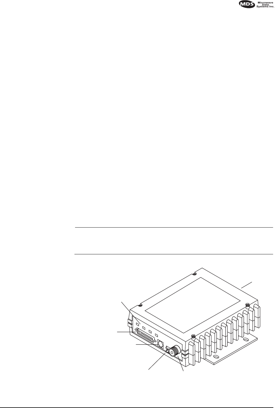
This guide presents installation and operating instructions for the MDS
4710/9710 Series (400/900 MHz) digital radio transceivers.
These transceivers (Figure 1) are data telemetry radios designed to
operate in a point-to-multipoint environment, such as electric utility
Supervisory Control and Data Acquisition (SCADA) and distribution
automation, gas field automation, water and wastewater SCADA, and
on-line transaction processing applications. They use microprocessor
control and Digital Signal Processing (DSP) technology to provide
highly reliable communications even under adverse conditions.
Modulation and demodulation is accomplished using Digital Signal Pro-
cessing (DSP). DSP adapts to differences between components from
unit to unit, and ensures consistent and repeatable performance in
ambient temperatures from –30 to +60 degrees Centigrade. The use of
Digital Signal Processing eliminates the fluctuations and variations in
modem operation that degrade operation of analog circuits.
The transceiver is designed for trouble-free operation with data equip-
ment provided by other manufacturers, including Remote Terminal
Units (RTUs), flow computers, lottery terminals, automatic teller
machines, programmable logic controllers, and others.
NOTE:
Some features may not be available on all radios, based on the
options purchased and based on the applicable regulatory
constraints for the region in which the radio will operate.
Invisible place holder
Figure 1. Transceiver Connectors and Indicators
EXTERNAL
INTERFACE
CONNECTOR
(DB-25)
DIAGNOSTICS
CONNECTOR (RJ-11)
13.8 VDC POWER
CONNECTOR
ANTENNA CONNECTOR
(TYPE “N”)
SERIAL NUMBER
LABEL
LED INDICATORS (4)
2 MDS 4710/9710 I/O Guide MDS 05-3305A01, Rev. B
1.2 Applications
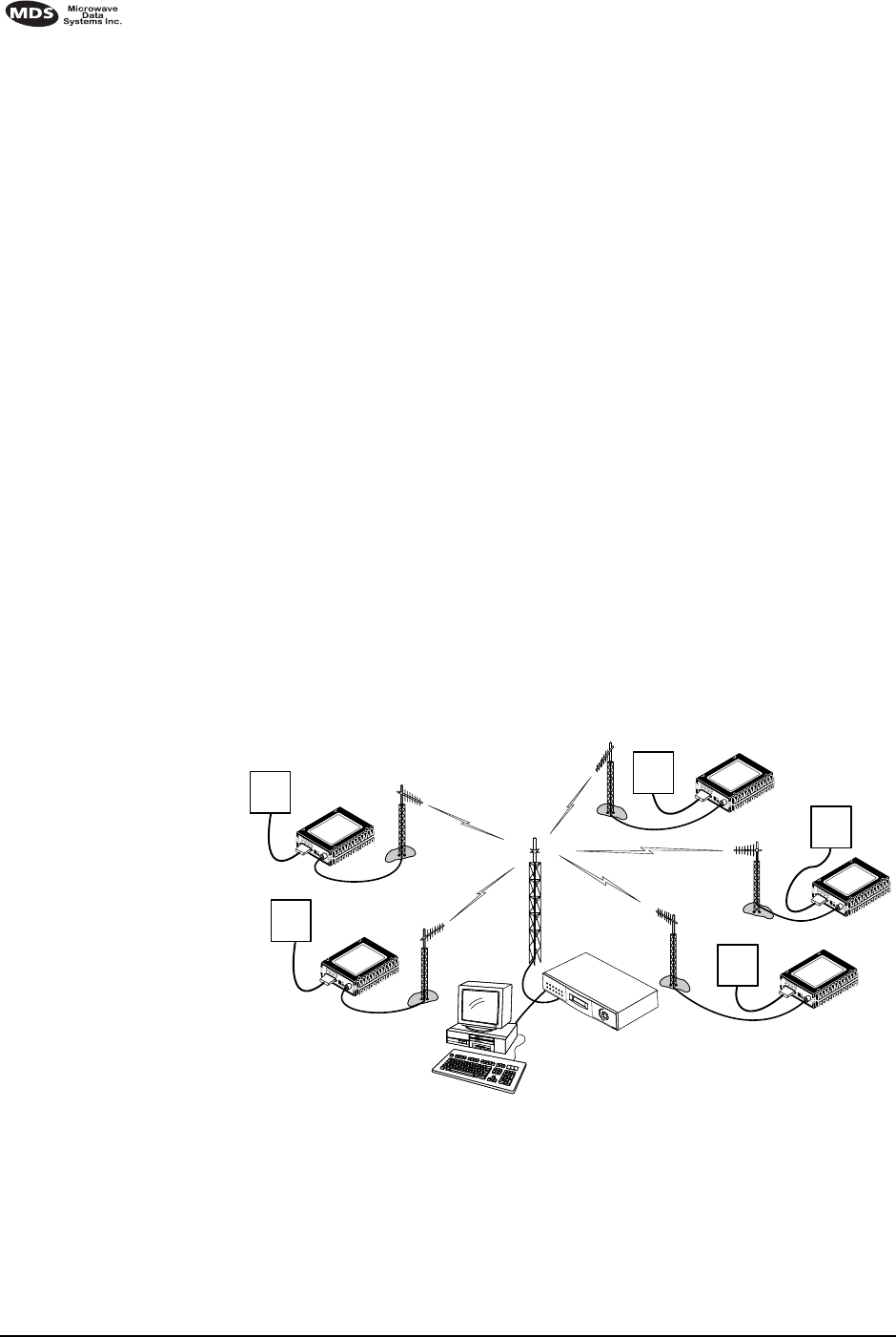
Point-to-Multipoint, Multiple Address Systems (MAS)
This is the most common application of the transceiver. It consists of a
central master station and several associated remote units as shown in
Figure 2. An MAS network provides communications between a central
host computer and remote terminal units (RTUs) or other data collection
devices. The operation of the radio system is transparent to the computer
equipment.
Often, however, a radio system consists of many widely separated
remote radios. A point-to-multipoint or SCADA (Supervisory Control
and Data Acquisition) system may be a new installation for automatic,
remote monitoring of gas wells, water tank levels, electric power distri-
bution system control and measurement, etc.
The radio system may replace a network of remote monitors currently
linked to a central location via leased telephone line. At the central
office of such a system, there is usually a large mainframe computer and
some means of switching between individual lines coming from each
remote monitor. In this type of system, there is a modulator/demodulator
(modem) at the main computer, and at each remote site, usually built
into the remote monitor itself. Since the cost of leasing a dedicated-pair
phone line is quite high, a desirable alternative may be replacing the
phone line with a radio path.
Invisible place holder
Figure 2. Typical MAS Point-to-Multipoint Network
IDIAG
13.8 VDC
PWR
+
HOST SYSTEM
REMOTE RADIO
SWC OFF
RTU
RTU
RTU
RTU
IDIAG
13.8 VDC
PWR
+
IDIAG
13.8 VDC
PWR
+
IDIAG
13.8 VDC
PWR
+
IDIAG
13.8 VDC
PWR
+
RTU
MDS MASTER
STATION
CONTINUOUSLY
KEYED
REMOTE RADIO
SWC OFF
REMOTE RADIO
SWC OFF
REMOTE RADIO
SWC OFF
REMOTE RADIO
SWC OFF

MDS 05-3305A01, Rev. B MDS 4710/9710 I/O Guide 3
Point-to-Point System
Where permitted, the transceiver may also be used in a point-to-point
arrangement.
A point-to-point system consists of just two radios—one
serving as a master and the other as a remote—as shown in Figure 3. It
provides a simplex or half-duplex communications link for the transfer
of data between two locations.
Invisible place holder
Figure 3. Typical Point-to-Point Link
Continuously Keyed versus Switched Carrier Operation
The keying behavior of the master station can be used to describe an
MAS system.
Continuously Keyed
operation means the master station transmitter is
always keyed and an RF carrier is always present, even when there is no
data to send. The master station is always simultaneously transmitting
and continuously listening. Different frequencies must be used for
transmit and receive. This is the method used in many MAS systems,
and is shown in Figure 2. This is useful for high-speed polling applica-
tions.
NOTE:
4710/9710 remotes do not support full-duplex operation.
Switched Carrier
operation is a half-duplex mode of operation where
the master station transmitter is keyed to send data and unkeyed to
receive.
Single Frequency (Simplex) Operation
Single frequency operation (also known as simplex) is a special case of
switched carrier operation. Single frequency operation is automatically
selected whenever the transmit and receive frequencies are set to the
same value. Note that data turn-around times are increased when a
single frequency configuration is used.
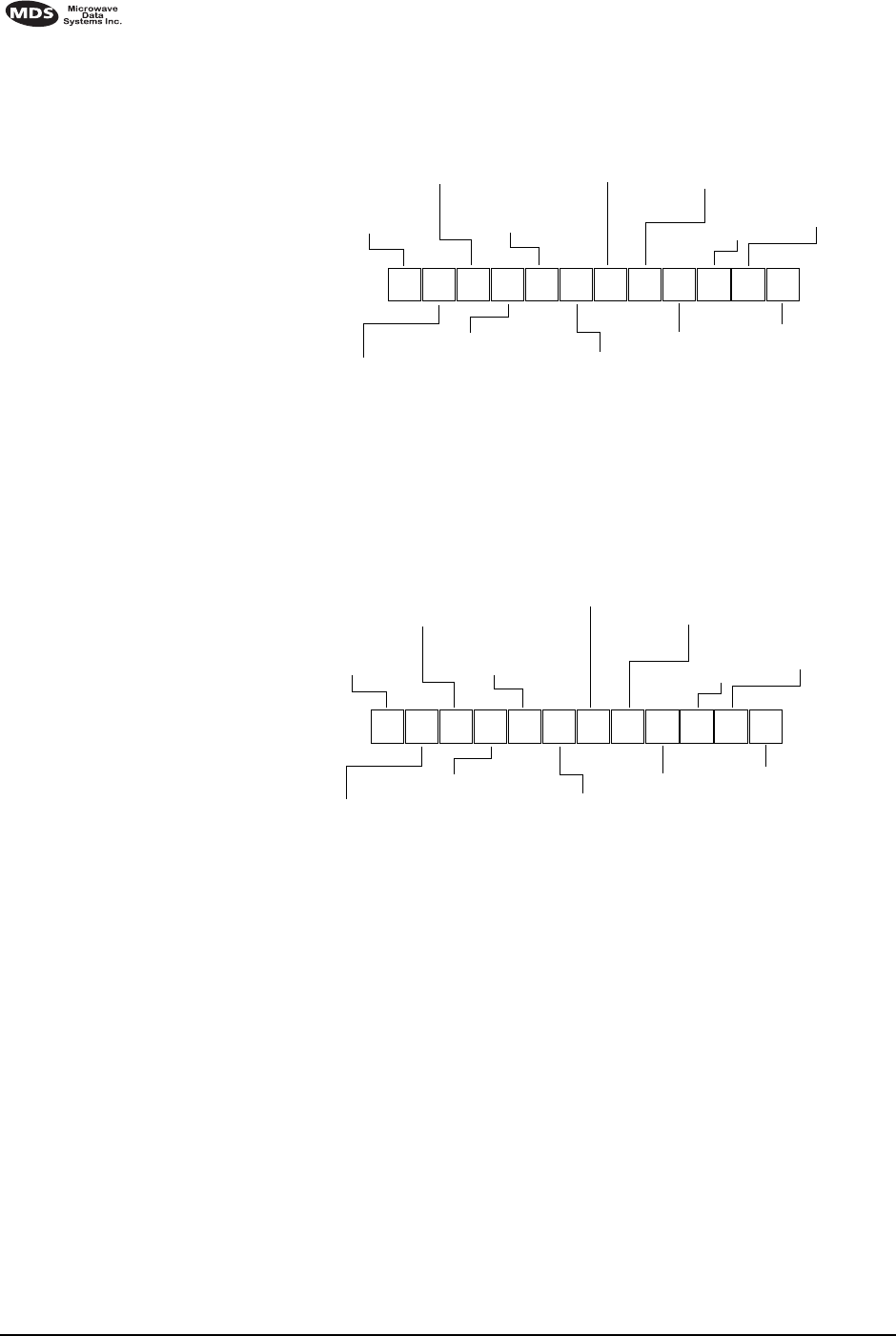
1.3 Model Number Codes
The radio model number is printed on the end of the radio enclosure, and
provides key information about how the radio was configured when it
was shipped from the factory. See Figure 4 and Figure 5 for an explana-
tion of the model number characters.
REMOTE
MASTER
HOST
COMPUTER
RTU
4 MDS 4710/9710 I/O Guide MDS 05-3305A01, Rev. B
Invisible place holder
Figure 4. 4710 Model Number Codes
Invisible place holder
Figure 5. 9710 Model Number Codes
1.4 Accessories
The transceiver can be used with one or more of the accessories listed in
Table 1. Contact Microwave Data Systems for ordering information.
THIS INFORMATION IS
SUBJECT TO
CHANGE.
DO NOT USE FOR
PRODUCT ORDERING. 4710A/C
OPERATION
X= Base/Remote
MODE
N= Non-redundant
INPUT VOLTAGE
1= 10.5 to 16 VDC
MODEM
B= 9600 BPS
DIAGNOSTICS
0= NONE
1= Non-Intrusive
BANDWIDTH
1= 12.5 KHz
2= 25 KHz (19.2 Kbps)
FEATURES
0= Full
AGENCY
N= N/A
SAFETY
N= N/A
MOUNTING BRACKETS
A= Standard
B= None
C= 19200 (25kHz)
RECEIVE FREQUENCY
(A) 380-400 MHz*
(B) 400-420 MHz
(C) 420-450 MHz
(D) 450-480 MHz
(E) 480-512 MHz
(L4) 406-430 MHz**
TRANSMIT FREQUENCY
(1) 380-400 MHz
*Not Available with FCC or IC
(2) 400-420 MHz
(3) 420-450 MHz
(4) 450-480 MHz**
** Only available with RX option
F= FCC/IC (F) CSA/FM/UL
(L4) 406-430 MHz
THIS INFORMATION IS
SUBJECT TO
CHANGE.
DO NOT USE FOR
PRODUCT ORDERING. 9710A/C
OPERATION
X= Base/Remote
MODE
N= Non-redundant
INPUT VOLTAGE
1= 10.5 to 16 VDC
MODEM
B= 9600 BPS
DIAGNOSTICS
0= NONE
1= Non-Intrusive
BANDWIDTH
1= 12.5 KHz
2= 25 KHz (19.2 Kbps)
FEATURES
0= Full
AGENCY
N= N/A
SAFETY
N= N/A
MOUNTING BRACKETS
A= Standard
B= None
C= 19200 (25kHz)
RECEIVE FREQUENCY
(A) 800-860 MHz*
(B) 860-900 MHz
(C) 900-960 MHz TRANSMIT FREQUENCY
(1) 800-880 MHz
*Not Available with FCC or IC
(2) 880-960 MHz
F= FCC/IC (F) CSA/FM/UL

MDS 05-3305A01, Rev. B MDS 4710/9710 I/O Guide 5
Table 1. MDS 4710/9710 Optional Accessories
Accessory Description MDS P/N
Hand-Held Terminal
Kit (HHT) Terminal that plugs into the radio for
programming, diagnostics & control.
Includes carrying case and cable set.
02-1501A01
RTU Simulator Test unit that simulates data from a
remote terminal unit. Comes with
polling software that runs on a PC.
Useful for testing radio operation.
03-2512A01
Order Wire Module External device that allows temporary
voice communication. Useful during
setup & testing of the radio system.
02-1297A01
Order Wire Handset Used with Order Wire Module (above). 12-1307A01
RJ-11 to DB-9 adapter Used to connect a PC to the radio’s
DIAG. port 03-3246A01
EIA-232 to EIA-422
Converter Assembly External adapter plug that converts the
radio’s DATA INTERFACE connector
to EIA-422 compatible signaling.
03-2358A01
Radio Configuration
Software Provides diagnostics of the transceiver
(Windows-based PC required.) 03-3156A01

6 MDS 4710/9710 I/O Guide MDS 05-3305A01, Rev. B
2.0 GLOSSARY OF TERMS
If you are new to digital radio systems, some of the terms used in this
guide may be unfamiliar. The following glossary explains many of these
terms and will prove helpful in understanding the operation of the trans-
ceiver.
Active Messaging
—This is a mode of diagnostic gathering that may
interrupt SCADA system polling communications (contrast with
pas-
sive messaging
). Active (or intrusive) messaging is much faster than
passive messaging because it is not dependent upon the RTU polling
cycle.
Antenna System Gain
—A figure, normally expressed in dB, repre-
senting the power increase resulting from the use of a gain-type antenna.
System losses (from the feedline and coaxial connectors, for example)
are subtracted from this figure to calculate the total antenna system gain.
Bit
—The smallest unit of digital data, often represented by a one or a
zero. Eight bits (plus start, stop, and parity bits) usually comprise a byte.
Bits-per-second
—See
BPS
.
BPS
—Bits-per-second. A measure of the information transfer rate of
digital data across a communication channel.
Byte
—A string of digital data usually made up of eight data bits and
start, stop and parity bits.
Decibel (dB)—A measure computed from the ratio between two signal
levels. Frequently used to express the gain (or loss) of a system.
Data Circuit-terminating Equipment—See DCE.
Data Communications Equipment—See DCE.
Data Terminal Equipment—See DTE.
dBi—Decibels referenced to an “ideal” isotropic radiator in free space.
Frequently used to express antenna gain.
dBm—Decibels referenced to one milliwatt. An absolute unit used to
measure signal power, as in transmitter power output, or received signal
strength.
DCE—Data Circuit-terminating Equipment (or Data Communications
Equipment). In data communications terminology, this is the “modem”
side of a computer-to-modem connection. The MDS 4710/9710 is a
DCE device.
Digital Signal Processing—See DSP.

MDS 05-3305A01, Rev. B MDS 4710/9710 I/O Guide 7
DSP—Digital Signal Processing. In the MDS 4710/9710 transceiver,
the DSP circuitry is responsible for the most critical real-time tasks; pri-
marily modulation, demodulation, and servicing of the data port.
DTE—Data Terminal Equipment. A device that provides data in the
form of digital signals at its output. Connects to the DCE device.
Equalization—The process of reducing the effects of amplitude, fre-
quency or phase distortion with compensating networks.
Fade Margin—The greatest tolerable reduction in average received
signal strength that will be anticipated under most conditions. Provides
an allowance for reduced signal strength due to multipath, slight antenna
movement or changing atmospheric losses. A fade margin of 20 to 30
dB is usually sufficient in most systems.
Frame—A segment of data that adheres to a specific data protocol and
contains definite start and end points. It provides a method of synchro-
nizing transmissions.
Hardware Flow Control—A transceiver feature used to prevent data
buffer overruns when handling high-speed data from the RTU or PLC.
When the buffer approaches overflow, the radio drops the clear-to-send
(CTS) line, which instructs the RTU or PLC to delay further transmis-
sion until CTS again returns to the high state.
Host Computer—The computer installed at the master station site,
which controls the collection of data from one or more remote sites.
Intrusive Diagnostics—A mode of remote diagnostics that queries and
commands radios in a network with an impact on the delivery of the
system “payload” data. See Active messaging.
Latency—The delay (usually expressed in milliseconds) between when
data is applied to TXD (Pin 2) at one radio, until it appears at RXD
(Pin 3) at the other radio.
MAS—Multiple Address System. A radio system where a central
master station communicates with several remote stations for the pur-
pose of gathering telemetry data.
Master (Station)—Radio which is connected to the host computer. It is
the point at which polling enters the network.
MCU—Microcontroller Unit. This is the processor responsible for con-
trolling system start-up, synthesizer loading, and key-up control.
Microcontroller Unit—See MCU.
Multiple Address System—See MAS.

8 MDS 4710/9710 I/O Guide MDS 05-3305A01, Rev. B
Network-Wide Diagnostics—An advanced method of controlling and
interrogating MDS radios in a radio network.
Non-intrusive diagnostics—See Passive messaging.
Passive messaging—This is a mode of diagnostic gathering that does
not interrupt SCADA system polling communications. Diagnostic data
is collected non-intrusively over a period of time; polling messages are
carried with SCADA system data (contrast with active messaging).
Payload data—This is the application’s user communication data
which is sent over the radio network. It is the transfer of payload data
that is the primary purpose of the radio communications network.
Point-Multipoint System—A radio communications network or
system designed with a central control station that exchanges data with
a number of remote locations equipped with terminal equipment.
Poll—A request for data issued from the host computer (or master PLC)
to a remote radio.
PLC—Programmable Logic Controller. A dedicated microprocessor
configured for a specific application with discrete inputs and outputs. It
can serve as a host or as an RTU.
Programmable Logic Controller—See PLC.
Remote (Station)—A radio in a network that communicates with an
associated master station.
Remote Terminal Unit—See RTU.
Redundant Operation—A station arrangement where two transceivers
and two power supplies are available for operation, with automatic
switchover in case of a failure.
RTU—Remote Terminal Unit. A data collection device installed at a
remote radio site. An internal RTU simulator is provided with
4710/9710 radios to isolate faults to either the external RTU or the radio.
SCADA—Supervisory Control And Data Acquisition. An overall term
for the functions commonly provided through an MAS radio system.
Standing Wave Ratio—See SWR.
Supervisory Control And Data Acquisition—See SCADA.
SWR—Standing Wave Ratio. A parameter related to the ratio between
forward transmitter power and the reflected power from the antenna
system. As a general guideline, reflected power should not exceed 10%
of the forward power (≈ 2:1 SWR).
MDS 05-3305A01, Rev. B MDS 4710/9710 I/O Guide 9
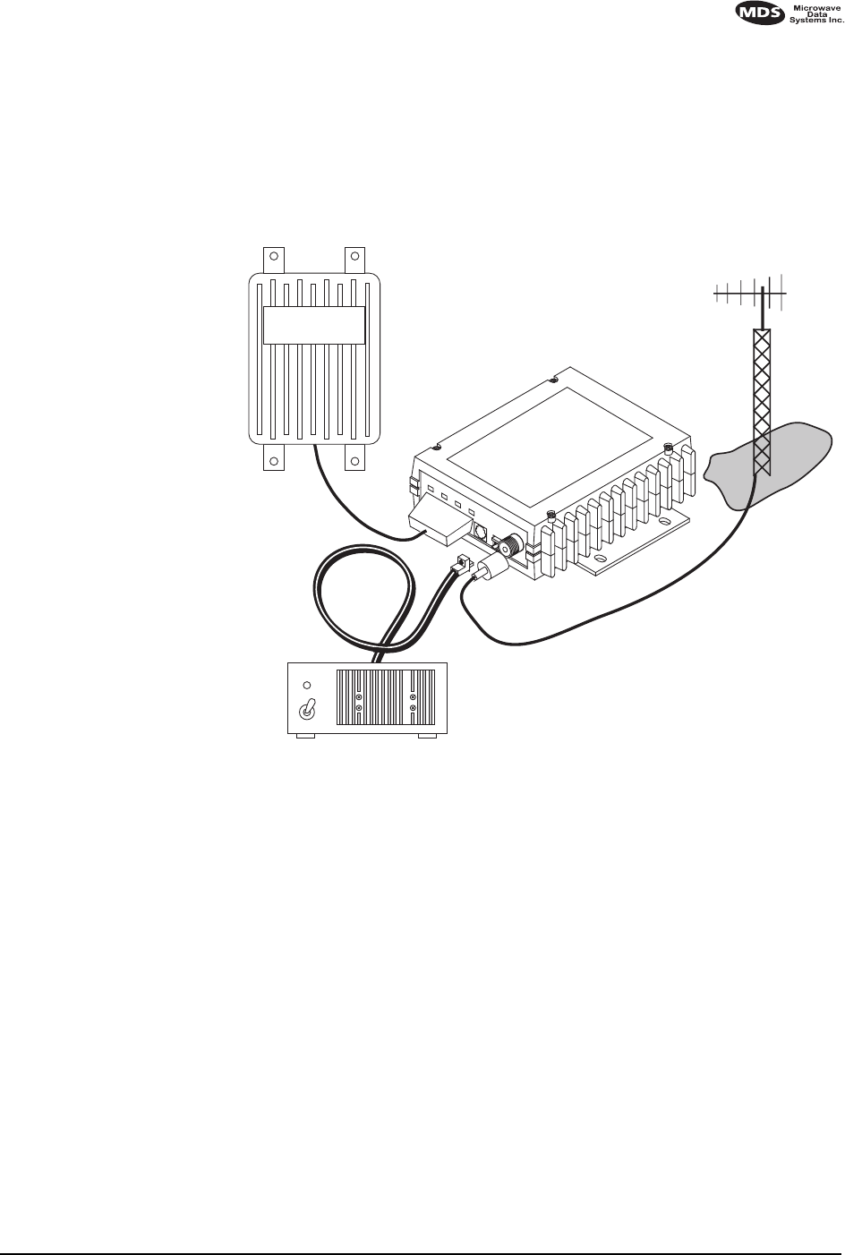
3.0 INSTALLATION
There are three main requirements for installing the transceiver—ade-
quate and stable primary power, a good antenna system, and the correct
data connections between the transceiver and the data device. Figure 6
shows a typical remote station arrangement.
Invisible place holder
Figure 6. Typical Remote Station Arrangement
3.1 Installation Steps
Below are the basic steps for installing the transceiver. In most cases,
these steps alone are sufficient to complete the installation. More
detailed explanations appear at the end of these steps.
1. Mount the transceiver to a stable surface using the brackets supplied
with the radio.
2. Install the antenna and antenna feedline for the station. Preset direc-
tional antennas in the desired direction.
3. Connect the data equipment to the transceiver’s DATA INTERFACE
connector. Use only the required pins for the application—Do not
use a fully pinned (25 conductor) cable. Basic applications may
require only the use of Pin 2 (transmit data—TXD), Pin 3 (Received
Data—RXD) and Pin 7 (signal ground). The radio can be keyed
13.8 VDC
POWER
CABLE
13.8 VDC
2.5 A (Minimum)
POWER SUPPLY
REMOTE TERMINAL
UNIT ANTENNA SYSTEM
LOW-LOSS FEEDLINE
RADIO
TRANSCEIVER

10 MDS 4710/9710 I/O Guide MDS 05-3305A01, Rev. B
with the use of the DATAKEY command.
Additional connections may be required for some installations.
Refer to the complete list of pin functions provided in Table 4 on
page 14.
4. Measure and install the primary power for the radio. The red wire on
the power cable is the positive lead; the black is negative.
NOTE: Use the radio in negative ground systems only.
5. Set the radio configuration. The transceiver is designed for quick
installation with a minimum of software configuration required in
most cases. The selections that must be made for new installations
are:
•Transmit frequency
•Receive frequency
The operating frequencies are not set at the factory unless they were
specified at the time of order. Determine the transmit and receive
frequencies to be used, and follow the steps below to program them.
6. Connect a hand-held terminal (HHT) to the DIAG. connector. When
the HHT beeps, press to receive the ready “>” prompt.
a. Set the operating frequencies using the TX xxx.xxxx (transmit) and
RX xxx.xxxx (receive) commands.
Press after each command. After programming, the HHT
reads PROGRAMMED OK to indicate successful entry.
ENTER
ENTER
MDS 05-3305A01, Rev. B MDS 4710/9710 I/O Guide 11
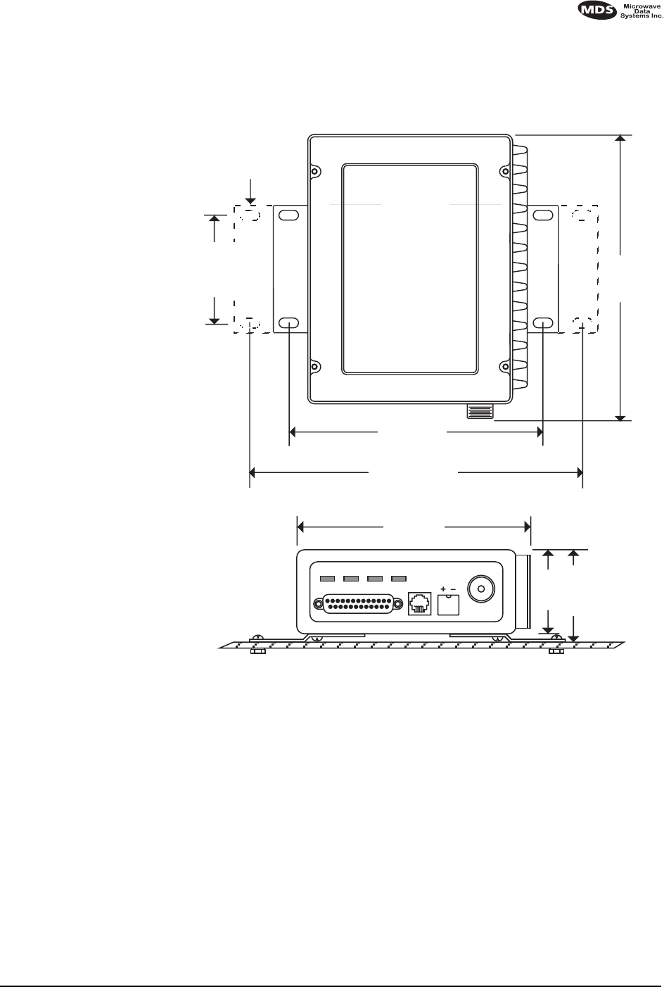
3.2 Transceiver Mounting
Figure 7 shows the mounting dimensions of the transceiver.
Invisible place holder
Figure 7. Transceiver Mounting Dimensions
3.3 Antennas and Feedlines
Antennas
The transceiver can be used with a number of antennas. The exact style
depends on the physical size and layout of the radio system. A direc-
tional Yagi (Figure 8) or corner reflector antenna is generally recom-
mended at remote sites to minimize interference to and from other users.
Antennas of this type are available from several manufacturers.
8.5"
216 mm
1.75"
4.44 CM
6.63"
168 mm
2.75"
70 mm
7.25"
184 mm
ALTERNATE
POSITION
5.625"
143 mm
2.25"
57 mm
2.0"
50 mm

12 MDS 4710/9710 I/O Guide MDS 05-3305A01, Rev. B
Invisible place holder
Figure 8. Typical Yagi Antenna (mounted to mast)
Feedlines
The selection of antenna feedline is very important. Poor quality cables
should be avoided as they will result in power losses that may reduce the
range and reliability of the radio system.
Table 2 and Table 3 show the losses that will occur when using various
lengths and types of cable at 400 and 960 MHz. Regardless of the type
of cable used, it should be kept as short as possible to minimize signal
loss.
Table 2. Length vs. Loss in Coaxial Cables at 400 MHz
Cable Type 10 Feet
(3.05 Meters) 50 Feet
(15.24 Meters) 100 Feet
(30.48 Meters) 500 Feet
(152.4 Meters)
RG-8A/U 0.51dB 2.53 dB 5.07 dB 25.35 dB
1/2 inch HELIAX 0.12 dB 0.76 dB 1.51 dB 7.55 dB
7/8 inch HELIAX 0.08 dB 0.42 dB 0.83 dB 4.15 dB
1-1/4 inch HELIAX 0.06 dB 0.31 dB 0.62 dB 3.10 dB
1-5/8 inch HELIAX 0.05 dB 0.26 dB 0.52 dB 2.60 dB
Table 3. Length vs. Loss in Coaxial Cables at 960 MHz
Cable Type 10 Feet
(3.05 Meters) 50 Feet
(15.24 Meters) 100 Feet
(30.48 Meters) 500 Feet
(152.4 Meters)
RG-8A/U 0.85 dB 4.27 dB 8.54 dB 42.70 dB
1/2 inch HELIAX 0.23 dB 1.15 dB 2.29 dB 11.45 dB
7/8 inch HELIAX 0.13 dB 0.64 dB 1.28 dB 6.40 dB
1-1/4 inch HELIAX 0.10 dB 0.48 dB 0.95 dB 4.75 dB
1-5/8 inch HELIAX 0.08 dB 0.40 dB 0.80 dB 4.00 dB

MDS 05-3305A01, Rev. B MDS 4710/9710 I/O Guide 13
3.4 Power Connection
The transceiver can be operated from any well-filtered 10.5 to 16 Vdc
power source. The power supply should be capable of providing at least
2.5 amperes of continuous current.
The red wire on the power cable is the positive lead; the black is nega-
tive.
NOTE: The radio is designed for use only in negative ground systems.
3.5 Data Interface Connections
The transceiver’s DATA INTERFACE connector is used to connect the
transceiver to an external DTE data terminal that supports the EIA-232
(formally RS-232) format. The transceiver supports asynchronous data
rates of up to 38400 bps. The data rate at the DATA INTERFACE connector
may differ from the data rate used over the air.
Table 4 lists each pin on the DATA INTERFACE connector and describes
its function.
Do not use a 25 wire (fully pinned) cable for connection to the DATA
INTERFACE connector. Use only the required pins for the application.
Damage may result if improper connections are made. Typical applica-
tions require the use of only Pins 1 through 8 for EIA-232 signaling.
3.6 Using the Radio’s Sleep Mode
In some installations, such as at solar-powered sites, it may be necessary
to keep the transceiver’s power consumption to an absolute minimum.
This can be accomplished using the Sleep Mode. In this mode, power
consumption is reduced to less than 16 milliamperes (nominal).
Sleep mode can be enabled under RTU control by asserting a ground (or
RS-232 low) on Pin 12 of the radio’s DATA INTERFACE connector.
When Pin 12 is opened (or an RS-232 high is asserted), the radio will be
ready to receive data within 75 milliseconds.
All normal functions are suspended while the radio is in sleep mode. The
PWR LED will be off, except for a quick flash every five seconds.
System Example
The following example describes Sleep Mode implementation in a typ-
ical system. Using this information, you should be able to configure a
system that will meet your own particular needs.
CAUTION
USE
ONLY REQUIRED
PINS

14 MDS 4710/9710 I/O Guide MDS 05-3305A01, Rev. B
Sleep Mode Example:
Suppose you need communications to each remote site only
once per hour. Program the RTU to raise an RS-232 line once
each hour (DTR for example) and wait for a poll and response
before lowering it again. Connect this line to Pin 12 of the
radio’s DATA INTERFACE connector. This will allow each RTU to
be polled once per hour with a significant savings in power con-
sumption.
Table 4. DATA INTERFACE Connector Pinouts
Pin
Number Input/
Output Pin Description
1--Protective Ground. Connects to ground (negative supply
potential) on the radio’s PC board and chassis.
2INTXD—Transmitted Data. Accepts TX data from the
connected device.
3 OUT RXD—Received Data. Outputs received data to the
connected device.
4INRTS—Request-to-Send Input. Keys the transmitter when
RTS is at logic high.
5 OUT CTS—Clear-to-Send Output. Goes “high” after the
programmed CTS delay time has elapsed (DCE) or keys
an attached radio when RF data arrives (CTS KEY).
6 OUT DSR—Data Set Ready. Provides a +6 Vdc DSR signal
through a 2.5 kΩ resistor.
7--Signal Ground. Connects to ground (negative supply
potential) at radio’s PC board.
8 OUT DCD—Data Carrier Detect. Goes “high” when the modem
detects a data carrier from the master station.
9INTransmit Audio Input. Connects to the audio output of an
external (AFSK) modem. The input impedance is 600 Ω.
Use Pin 7 for the modem’s return lead.
10 OUT RUS—Receiver Unsquelched Sensor. Not used in most
installations, but is available as a convenience. Provides
+8 Vdc through a 1 kΩ resistor whenever the receiver
squelch is open, and drops to less than 1 Vdc when the
squelch is closed.
11 OUT Receive Audio Output. Connects to the audio input of an
external (AFSK) modem. The output impedance is 600 Ω,
and the level is factory set to suit most installations. Use
Pin 7 for the modem’s return lead.
12 IN Radio Inhibit (Sleep). A ground on this pin places the
radio into the “sleep” mode. It turns off most circuits in the
radio, including transmit, receive, modem and diagnostic
functions. This allows for greatly reduced power
consumption, yet preserves the radio’s ability to be quickly
brought online.
13 -- Do not connect—Reserved for future use.
14 IN PTT—Push to Talk. This line is used to key the radio with
an active-high signal of +5 Vdc.

MDS 05-3305A01, Rev. B MDS 4710/9710 I/O Guide 15
Invisible place holder
4.0 OPERATION
In-service operation of the transceiver is completely automatic. Once
the unit has been properly installed and configured, operator actions are
limited to observing the front panel LED status indicators for proper
operation.
If all parameters are correctly set, operation of the radio can be started
by following these steps:
1. Apply DC power to the transceiver.
2. Observe the LED status panel for the proper indications (Table 5).
3. If not done earlier, refine the antenna heading of the station to maxi-
mize the received signal strength (RSSI) from the master station.
Use the RSSI command from an HHT connected to the radio’s DIAG.
15 -- .Remote RTU Reset. Do not connect. Reserved for future
use.
16 IN PTT—Push to Talk. This line is used to key the radio with
an active-low signal of 0 Vdc.
17 -- Do not connect—Reserved for future use.
18 IN/OUT Accessory Power. Unregulated Input/Output. Provides a
source of input power for low current accessories.
Excessive drain on this connection will trip self-resetting
fuse F1 on the transceiver PC board. The voltage at this
pin will match the input voltage to the transceiver.
19 OUT 9.9 Vdc Regulated Output. Provides a source of
regulated voltage at 100 mA for low power accessories.
20 -- Do not connect—Reserved for future use.
21 OUT RSSI—Received Signal Strength Indication. A DC
voltmeter may be connected to this pin to read the relative
strength of the incoming signal. Figure 9 is a chart showing
RSSI vs. DC voltage.
22 -- Do not connect—Reserved for future use.
23 IN Diagnostic Channel Enable. A ground on this pin causes
the radio’s microcontroller to open the DB-25 DATA
INTERFACE for diagnostics and control instead of the
normal RJ-11 DIAG. connection.
24 -- Do not connect—Reserved for future use.
25 OUT Alarm. A logic low (less than 0.5 volts) on this pin indicates
normal operation. A logic high (greater than 4 volts)
indicates that some alarm condition is present. This pin
can be used as an alarm output, provided the internal
series resistance of 1 kΩ is considered.
Table 4. DATA INTERFACE Connector Pinouts (Continued)
Pin
Number Input/
Output Pin Description

16 MDS 4710/9710 I/O Guide MDS 05-3305A01, Rev. B
connector.—See Section 5.0, TRANSCEIVER PROGRAMMING on
page 17. This can also be done with a DC voltmeter as described in
Section 4.2, RSSI Measurement (page 16).
4.1 LED Indicators
Table 5 describes the function of each status LED.
4.2 RSSI Measurement
As an alternative to using an HHT, the radio’s received signal strength
(RSSI) may be read with a DC voltmeter connected to Pin 21 of the DATA
INTERFACE connector. Figure 9 shows the relationship between
received signal level and the DC voltage on Pin 21 of the DATA INTER-
FACE connector. (Note: Readings are not accurate for incoming signal
strengths above –50 dBm.)
Invisible place holder
Figure 9. RSSI vs. Vdc (Typical)
PWR DCD TXD RXD
Table 5. LED Status Indicators
LED Name Description
PWR • Continuous—Power is applied to the radio, no problems detected.
• Rapid flash (five times per second)—Fault indication.
• Flashing once every 5 seconds—Radio is in Sleep mode.
DCD • Flashing—Indicates the radio is receiving intermittent data frames.
• Continuous—Radio is receiving a data signal from a continuously
keyed radio.
TXD An EIA-232 mark signal is being received at the DATA INTERFACE
connector.
RXD An EIA-232 mark signal is being sent out from the DATA INTERFACE
connector.
2
2.5
3
3.5
4
–110
–90
–70
–50
+ DC VOLTS (PIN 21)
SIGNAL LEVEL (dBm)
4.5
5.0

MDS 05-3305A01, Rev. B MDS 4710/9710 I/O Guide 17
5.0 TRANSCEIVER PROGRAMMING
Programming and control of the transceiver is performed through the
radio’s RJ-11 DIAG. (Diagnostics) connector with an MDS Hand-Held
Terminal (MDS P/N 02-1501A01). This section contains a reference
chart (Table 7) and detailed descriptions for each user command.
NOTE: In addition to HHT control, Windows-based software is avail-
able (MDS P/N 03-3156A01) to allow diagnostics and
programming using a personal computer. An installation
booklet and on-line instructions are included with the soft-
ware. Contact MDS for ordering information.
5.1 Hand-Held Terminal Connection & Startup
This section gives basic information for connecting and using the MDS
Hand-Held Terminal. For more information about the terminal, refer
also to the instructions included with each HHT kit.
The steps below assume that the HHT has been configured for use with
the transceiver (80 character screen display). If the HHT was previously
used with a different model transceiver, or if its default settings have
been changed, refer to Section 5.2, Hand-Held Terminal Setup (page 18)
for setup details.
Follow these steps to connect the HHT:
1. Connect the HHT’s coiled cord to the DIAG. (RJ-11) jack on the radio
as shown in Figure 10. This automatically places the radio into the
control and programming mode.
As an alternative, the DATA INTERFACE (DB-25) connector may be
used for programming instead of the DIAG. jack. With this arrange-
ment, Pin 23 of the HHT cable must be grounded to enable the diag-
nostic channel. (See Table 4 on page 14.)
2. When the HHT is connected, it runs through a brief self-check,
ending with a beep. After the beep, press to receive the
ready “>” prompt. ENTER
18 MDS 4710/9710 I/O Guide MDS 05-3305A01, Rev. B
Invisible place holder
Figure 10. Hand-Held Terminal Connected to the Transceiver
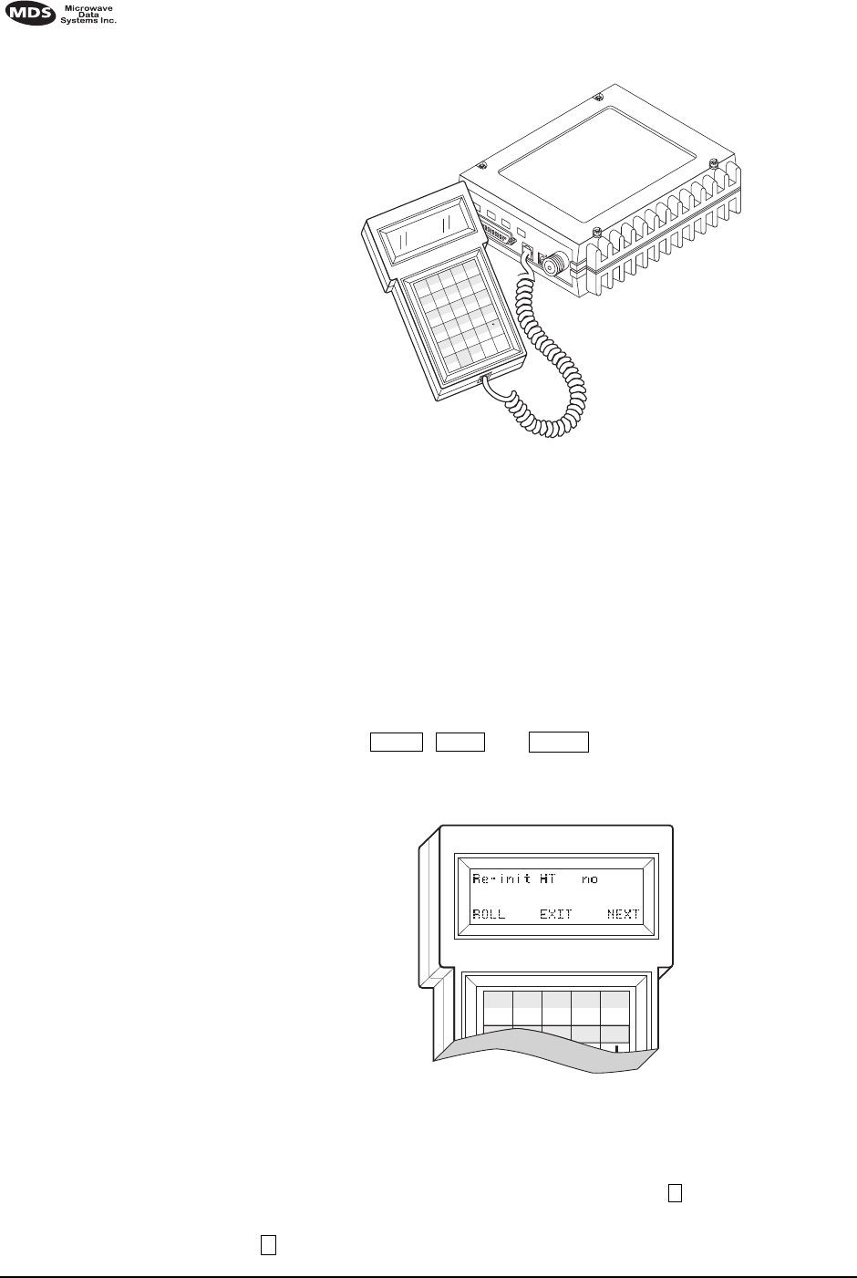
5.2 Hand-Held Terminal Setup
The following is a set of instructions for re-initializing an HHT for use
with the transceiver. These steps may be required if the HHT was previ-
ously used with a different radio, or if the HHT default settings have
been inadvertently altered.
1. Plug the HHT into the DIAG. connector. Enable the setup mode by
pressing the , and keys in sequence. The display
shown in Figure 11 appears.
Invisible place holder
Figure 11. HHT Setup Display
2. The first of 15 menu items is displayed. Settings are reviewed by
pressing the NEXT function controlled by the key. Parameter set-
tings are changed by pressing the ROLL function controlled by the
key.
ANTENNA
13.8 VDC
+ –
Z
CTRL
U
+
–
K
*
F
/
A
F1
V
,
Q
#
)
G
(
B
F2
SHIFT ESC
W
=
R
7
M
4
H
1
C
F3
BKSP
X
0
S
8
N
5
I
2
D
F4
SPACE
Y
T
9
O
6
3
E
F5
ENTER
J
L
P
SHIFT
CTRL
SPACE
FF
1
FFF
E
A

MDS 05-3305A01, Rev. B MDS 4710/9710 I/O Guide 19
3. Set up the HHT as listed in Table 6.
5.3 Keyboard Commands
Table 7 is a reference chart of software commands for the transceiver.
Programmable information is shown in brackets [ ] following the com-
mand name. See Section 5.4, Detailed Command Descriptions (page 22)
for detailed command descriptions.
Entering Commands
To enter a command, type the command, followed by an key-
stroke. For programming commands, the command is followed by
and the appropriate information or values, then .
Here are some additional points to remember when using the HHT:
•Use the key to access numbers; press again to return to letter
mode.
•Use the key to edit information or commands entries.
•The flashing square cursor ( ) indicates that letter mode is
selected.
•The flashing superscript rectangular cursor ( ) indicates that
number mode is selected.
Error Messages
Listed below are some possible error messages encountered when using
the HHT:
UNKNOWN COMMAND—The command was not recognized. Refer to the
command description for command usage information.
INCORRECT ENTRY—The command format or its associated values were
not valid. Refer to the command description for command usage infor-
mation.
Table 6. HHT Operational Settings
Parameter Setting Parameter Setting
Re-init HT NO Scroll On 33rd
Baud Rate 9600 Cursor ON
Comm bits 8,1,n CRLF for CR OFF
Parity Error OFF Self Test FAST
Key Repeat OFF Key Beep ON
Echo OFF Screen Size 80
Shift Keys YES Menu Mode LONG
Ctl Chars PROCS
ENTER
SPACE ENTER
SHIFT
ESC/BKSP

20 MDS 4710/9710 I/O Guide MDS 05-3305A01, Rev. B
COMMAND FAILED—The command was unable to successfully complete.
This is a possible internal software problem.
NOT PROGRAMMED—Software was unable to program the internal radio
memory or the requested item was not programmed.This is a serious
internal radio error. Contact MDS.
TEXT TOO LONG—Response to OWN or OWM command when too many
characters have been entered. Refer to the command description for
command usage information.
NOT AVAILABLE—The entered command or parameter was valid, but it
referred to a currently unavailable choice. Refer to the command
description for command usage information.
ACCESS DENIED—The command is unavailable to the user. Refer to the
command descriptions for command information.
EEPROM FAILURE— The INIT command was unable to write to EEPROM.
This is a serious internal radio error. Contact MDS.
Table 7. Command summary
Command name Function
AMASK [0000 0000–FFFF
FFFF] Details page 22 Set or display hex code identifying which events
trigger an alarm.
ASENSE [HI/LO] Details
page 23 Set or display the state of the alarm output signal
to ACTIVE HI or ACTIVE LO.
BAUD [xxxxx abc] Details
page 23 Set or display the DATA INTERFACE data rate
and control bits.
BUFF [ON, OFF] Details
page 24 Enables or disables the internal radio data buffer.
CTS [0–255] Details page
24 Set or display the Clear-to-Send delay in
seconds.
CKEY [ON–OFF] Details
page 24 Enables or disables the continuously keyed
mode. Note: Remotes cannot receive when
keyed.
DATAKEY [ON, OFF]
Details page 24 Toggles between key-on-data and key-on-RTS.
DKEY Details page 25 Dekey the radio (transmitter OFF). This is
generally a radio test command.
DLINK [ON/OFF/xxxx]
Details page 25 Configures local diagnostic link protocol.
DMGAP [xx] Details page
25 (diagnostics) Sets the amount of time to wait after
the receipt of a character before interpreting the
next received character as the start of a new
message.
DTYPE [NODE/ROOT]
Details page 26 (diagnostics) Sets up a radio as a root or node
radio.

MDS 05-3305A01, Rev. B MDS 4710/9710 I/O Guide 21
DUMP Details page 26 Display all programmable settings.
HREV Details page 26 Display the Hardware Revision level.
INIT Details page 26 Set radio parameters to factory defaults.
INIT [4710/9710] Details
page 26 Configure radio for use without P-20 chassis.
Restores certain transceiver defaults before using
the INIT x720 command.
INIT [4720/9720] Details
page 27 Configure radio for use with P-20 chassis.
KEY Details page 27 Key the radio (transmitter ON). This is generally a
radio test command.
MODEL Details page 27 Display the model number of the radio.
MODEM [xxxx, NONE]
Details page 27 Set the modem characteristics of the radio.
OWM [XXX...] Details page
27 Set or display the owner’s message.
OWN [XXX...] Details page
27 Set or display the owner’s name.
PTT [0–255] Details page
27 Set or display the Push-to-Talk delay in
milliseconds.
PWR [20–37] Details page
27 Set or display the transmit power setting.
RSSI Details page 28 Display the Received Signal Strength Indication.
RTU [ON/OFF/0-80] Details
page 28 Re-enables or disables the radio’s internal RTU
simulator and sets the RTU address.
RX [xxx.xxxx] Details page
28 Set or display receiver frequency.
RXTOT [NONE, 1-255]
Details page 28 Set or display the value of the receive time-out
timer.
SCD [0-255] Details page
29 Set or display the Soft-carrier Dekey delay in
milliseconds.
SER Details page 29 Display the radio serial number.
SHOW [DC, PORT, PWR]
Details page 29 Display the DC voltages, diagnostics port, and
transmit power level.
SREV Details page 29 Display the Software Revision Level.
STAT Details page 29 Display radio status and alarms.
TEMP Details page 30 Display the internal temperature of the radio in
degrees C.
TOT [1-255, ON, OFF]
Details page 30 Set or display the Time-out Timer delay in
seconds.
TX [xxx.xxxx] Details page
30 Set or display the transmit frequency.
UNIT [10000...65000]
Details page 30 Set or display the transceiver’s unit address.
Table 7. Command summary (Continued)
Command name Function

22 MDS 4710/9710 I/O Guide MDS 05-3305A01, Rev. B
5.4 Detailed Command Descriptions
The only critical commands for most applications are transmit and
receive frequencies (RX xxx.xxxx, TX xxx.xxxx). However, proper use of the
additional commands allows you to tailor the transceiver for a specific
use, or conduct basic diagnostics on the radio. This section gives more
detailed information for the user commands previously listed in Table 7
(page 20).
In many cases, the commands shown here can be used in two ways.
First, you can type only the command name to view the currently pro-
grammed data. Secondly, you can set or change the existing data by
typing the command, followed by a space, and then the desired entry. In
the list below, allowable programming variables, if any, are shown in
brackets following the command name.
AMASK [0000 0000–FFFF FFFF]
The AMASK command displays or sets which events cause the alarm
output signal to be active. Normally, the mask is FFFF FFFF, meaning that
any of the 32 possible events will activate the alarm output signal.
Entering the AMASK command alone displays the current setting of
alarm events in hexadecimal format.
Entering the AMASK command followed by an eight-digit hexadecimal
number reprograms the specified events to trigger an alarm.
The eight-digit hexadecimal number used as the command parameter is
used to classify up to 32 events as alarm triggers, or disable alarm noti-
fication for an event. (See Table 8 below for a list of events.) The hex
value for the mask corresponds to the hex value for the STAT command
(page 29). Each bit that is a ‘1’ identifies the associated alarm condition
as a major alarm. Each bit that is a ‘0’ disables major alarm notification
for that condition. If both the major and minor alarm bits are set to ‘0’
for that condition, alarm notification is entirely disabled. For more infor-
mation on configuring the alarm response, contact Microwave Data Sys-
tems.
Table 8. Text messages of alarm event codes
Event Number Text Message
01 Hardware mismatch
02 Model number not programmed
03 Authorization fault
04 Synthesizer out-of-lock
07 Voltage regulator fault detected
08 Radio not calibrated
09 DSP download fault
10 EEPROM write failure

MDS 05-3305A01, Rev. B MDS 4710/9710 I/O Guide 23
ASENSE [HI/LO]
The ASENSE command sets or displays the sense of the alarm output at
Pin 25 of the DATA INTERFACE connector.
Entering the ASENSE command alone shows whether the alarm output is
active high or low. Entering the ASENSE command followed by HI or LO
resets the alarm output to active high or low.
BAUD [xxxxx abc]
This command sets (or displays) the communication attributes for the
DATA INTERFACE port. It has no effect on the RJ-11 DIAG. port.
The first parameter (xxxxx) is baud rate. Baud rate is specified in
bits-per-second (bps) and must be one of the following speeds: 110, 300,
1200, 2400, 4800, 9600, 19200, or 38400.
The second parameter of the BAUD command (abc) is a three-character
block indicating how the data is encoded:
a = Data bits (7 or 8)
b = Parity (N for None, O for Odd, E for Even)
c = Stop bits (1 or 2)
The factory default setting is 9600 baud, 8 data bits, no parity, 1 stop bit
(Example: 9600 8N1).
NOTE: 7N1, 8O2, and 8E2 are invalid communication settings and are
not supported by the transceiver.
11 Checksum fault
12 Receiver time-out
16 Unit address not programmed
17 Data parity error
18 Data framing error
20 Configuration error
25 6V regulator output not in valid range
26 DC input power is not in valid range
31 Internal Temperature not in valid range
Table 8. Text messages of alarm event codes (Continued)
Event Number Text Message

24 MDS 4710/9710 I/O Guide MDS 05-3305A01, Rev. B
BUFF [ON, OFF]
This command sets or displays the received data handling mode of the
radio. The command parameter is either ON or OFF. The default is ON.
The setting of this parameter affects the timing of how received RF data
is sent out the INTERFACE connector. Outgoing (transmitted) data is not
affected by this setting.
If data buffering is OFF, the radio operates with the lowest possible
average latency. Data bytes are thus sent out the INTERFACE port as soon
as an incoming RF data frame is disassembled. Average and typical
latency will both be below 10 ms, but idle character gaps may be intro-
duced into the outgoing data flow.
If data buffering is ON, the radio operates in seamless mode. Data bytes
will be sent over the air as quickly as possible, but the receiver buffers
(stores) the data until enough bytes have arrived to cover worst-case
gaps in transmission. This mode of operation is required for protocols
such as MODBUS™ that do not allow gaps in their data transmission.
Note that seamless mode (BUFF ON) is intended only for applications
where the transmitter’s baud rate is greater than or equal to the
receiver’s baud rate. Enforcement of this rule is left up to the user.
CKEY [ON–OFF]
The CKEY command enables or disables the continuously-keyed func-
tion of the radio. When CKEY is set to ON, the radio is continuously
keyed.
CTS [0–255]
The CTS (clear-to-send) command selects or displays the timer value
associated with the CTS line response. The command parameter ranges
from 0 to 255 milliseconds.
For DCE operation, the timer specifies how long to wait after the RTS
line goes high, before the radio asserts CTS and the DTE can transmit
the data. A CTS value of zero keys the radio and asserts the CTS line
immediately after the RTS line goes high.
For CTS Key operation (see DEVICE command), the timer specifies how
long to wait after asserting the CTS, before sending data out the DATA
INTERFACE port. A timer value of zero means that data will be sent out
the data port without imposing a key-up delay. (Other delays may be
present based on selected radio operating parameters.)
DATAKEY [ON, OFF]
The DATAKEY command enables or disables the ability of the radio to key
the transmitter as data is received at the DATA INTERFACE connector.
Asserting RTS keys the radio regardless of this command setting.

MDS 05-3305A01, Rev. B MDS 4710/9710 I/O Guide 25
If DATAKEY is set to ON, the radio will key when a full data-character is
received at the transceiver’s DATA INTERFACE connector. If DATAKEY is
set to OFF, the radio needs to be keyed by asserting either the RTS or
PTT signal or with the CKEY or KEY command.
DEVICE [DCE, CTS KEY]
The DEVICE command controls or displays the device behavior of the
radio. The command parameter is either DCE or CTS KEY.
The default selection is DCE. In this mode, CTS will go high following
RTS, subject to the CTS programmable delay time. If the DATAKEY com-
mand is set to ON, keying can be stimulated by the input of characters at
the data port. Hardware flow control is implemented by signaling the
CTS line if data arrives faster than it can be buffered and transmitted.
If CTS KEY is selected, the radio is assumed to be controlling another
radio. The RTS line is ignored and the CTS line is used as a keyline con-
trol for the other radio. CTS is asserted immediately following the
receipt of RF data, but data will not be sent out the DATA INTERFACE port
until after the CTS programmable delay time has expired. (This gives
the other radio time to key.)
DKEY
This command deactivates the transmitter after it has been keyed with
the KEY command.
DLINK [ON/OFF/xxxx]
This command is used to configure the local diagnostic link protocol
used in network-wide diagnostics.
Entering DLINK ON enables the diagnostic link. Entering DLINK OFF dis-
ables the diagnostic link.
To change the diagnostic link, enter DLINK followed by one of the fol-
lowing baud rates: 1200, 2400, 4800, 9600, 19200 (default).
DMGAP [xx]
The DMGAP command sets the amount of time in milliseconds to wait
after the receipt of a character before interpreting the next received char-
acter as the start of a new message. When data port baud rates are slow,
the gap between characters within a poll may be so long that the radio
interprets the next character as the start of a new poll. When diagnostics
is being performed using passive messaging (see Performing Net-
work-Wide Remote Diagnostics on page 37), this command may be used
to change this behavior.

26 MDS 4710/9710 I/O Guide MDS 05-3305A01, Rev. B
DTYPE [NODE/ROOT]
This command establishes the local radio as a root radio or node radio
for network-wide diagnostics. Entering DTYPE NODE configures the
radio as a node radio. Entering DTYPE ROOT configures the radio as a root
radio. Entering the DTYPE command alone displays the current setting.
See “Performing Network-Wide Remote Diagnostics” on page 37.
DUMP
This command displays all the programmed settings with this one com-
mand. The HHT display is too small to list all the command settings at
one time. Therefore, this command is most useful if the command is
issued from a computer or full-screen terminal.
HREV
This command displays the transceiver’s hardware revision level.
INIT
The INIT command is used to re-initialize the radio’s operating parame-
ters to the factory defaults. This may be helpful when trying to resolve
configuration problems that may have resulted from the entry of one or
more improper command settings. If you are unsure of which command
setting may have caused the problem, this command allows you to get
back to a known working state. The following changes to the radio are
made when INIT is entered:
•CTS is set to 0
•DATAKEY is set to ON
•DEVICE is set to DCE
•PTT is set to 0
•SCD is set to 0
•TOT is set to 30 seconds and set to ON
•PWR is set to +37 dBm (5 watts)
All other commands stay in the previously established setting.
INIT [4710/9710]
This command sets the transceiver for operation outside the P-20 chassis
by setting the following parameters as shown:
ASENSE ACTIVE HI
AMASK FFFF FFFF (assert alarm output on all alarms)
RXTOT NONE (receive time-out timer disabled)
This command can be used prior to using the INIT x720 command to
restore the standard transceiver defaults

MDS 05-3305A01, Rev. B MDS 4710/9710 I/O Guide 27
INIT [4720/9720]
This command sets the transceiver for operation inside the P-20 chassis
by setting the following parameters as shown:
ASENSE ACTIVE LO
AMASK FFFF 0000 (trigger on major alarms)
RXTOT 20 (20 minute time-out timer)
KEY
This command activates the transmitter. See also the DKEY command.
MODEL
This command displays the radio’s model number code.
MODEM [xxxx, NONE]
This command selects the radio’s modem characteristics. For digital
operation enter 9600 (MDS x710A) or 19200 (MDS x710C). For analog
operation, enter NONE.
OWM [XXX...]
This is a command to display or program an owner’s message. To pro-
gram the owner’s message, type OWM then the message, followed by
.
To display the owner’s message, type OWM then . The owner’s
message appears on the display.
OWN [XXX...]
This is a command to display or program an owner’s name. To program
the owner’s name, type OWN then the name, followed by .
To display the owner’s name, type OWN then . The owner’s
name appears on the display.
PTT [0–255]
This command sets or displays the key-up delay in milliseconds.
This timer specifies how long to wait after the radio receives a key signal
from either the PTT or RTS lines (on the DATA INTERFACE), before actu-
ally keying the radio.
PWR [20–37]
NOTE: This function may not be available, depending on certification
requirements in a particular country.
ENTER
ENTER
ENTER
ENTER

28 MDS 4710/9710 I/O Guide MDS 05-3305A01, Rev. B
This command displays or sets the desired RF forward output power set-
ting of the radio. The PWR command parameter is specified in dBm and
can range from 20 through 37. The default setting is 37 dBm (5 watts).
To read the actual (measured) power output of the radio, use the SHOW
PWR command. A dBm-to-watts conversion chart is provided in
Section 7.5 (page 40).
RSSI
This command continuously displays the radio’s Received Signal
Strength Indication (RSSI) in dBm units, until you press the Enter key.
Incoming signal strengths from –50 dBm to –120 dBm can be read.
RTU [ON/OFF/0-80]
This command re-enables or disables the radio’s internal RTU simu-
lator, which runs with MDS’ proprietary polling programs (poll.exe and
rsim.exe). The internal RTU simulator is available whenever a radio has
diagnostics enabled. This command also sets the RTU address that the
radio will respond to.
The internal RTU can be used for testing system payload data or pseudo
bit error rate testing. It can be helpful in isolating a problem to either the
external RTU or the radio.
RX [xxx.xxxx]
This command selects or displays the radio’s receive frequency in MHz.
The frequency step size is 6.25 kHz.
If the customer frequency has not been programmed at the factory, a
default frequency will be programmed in the radio near the center of the
frequency band.
NOTE: A large change in receive frequency (more than 5 MHz)
requires adjustment of the receiver helical filters for maximum
performance and RSSI. See Section 7.2, Helical Filter Adjust-
ment (page 36) for details.
RXTOT [NONE, 1-255]
The RXTOT command selects or displays the receive time-out timer value
in minutes. This timer triggers an alarm (event 12) if data is not detected
within the specified time.
Entering the RXTOT command without a parameter displays the timer
value in minutes. Entering the RXTOT command with a parameter
ranging from 0 to 255 resets the timer in minutes. Entering the RXTOT
command with the parameter NONE disables the timer.

MDS 05-3305A01, Rev. B MDS 4710/9710 I/O Guide 29
SCD [0-255]
This command displays or changes the soft-carrier dekey delay in milli-
seconds.
This timer specifies how long to wait after the removal of the keying
signal before actually releasing the transmitter. A value of 0 millisec-
onds will unkey the transmitter immediately after the removal of the
keying signal.
SER
This command displays the radio’s serial number as recorded at the fac-
tory.
SHOW [DC, PORT, PWR]
The SHOW command displays different types of information based on
the command variables. The different parameters are:
•DC—Display DC input/output voltages
•PORT—Display the connector port (RJ-11 or DB-25) that is active
for diagnostics and control.
•PWR—Display RF power output
SNR
This command continuously displays the signal-to-noise ratio of the
received signal expressed in dB, until you press the Enter key. As used
in this guide, the signal-to-noise measurement is based upon the signal
level following equalization, for received frames.
The SNR is an indication of the received signal quality. The SNR indi-
cation ranges from 10 dB to 33 dB. A value of 10 dB represents a very
poor signal. A value of 24 dB represents a very good signal.
When the SNR command is used, it causes the DIAG. port to enter an
update mode, and the signal-to-noise ratio is updated and redisplayed
every 2 seconds. The SNR continuously updates until the key is
pressed.
SREV
This command displays the software revision level of the transceiver
firmware.
STAT
This command displays the current alarm status of the transceiver.
If no alarms exist, the message NO ALARMS PRESENT appears at the top
of the HHT display.
ENTER

30 MDS 4710/9710 I/O Guide MDS 05-3305A01, Rev. B
If an alarm does exist, a two-digit code (00–31) is displayed and the
alarm is identified as “Major” or “Minor.” A brief description of the
alarm code is also given.
If more than one alarm exists, the word MORE appears at the bottom of
the screen and additional alarms are viewed by pressing the
key. Detailed descriptions of event codes are provided in Table 9 on
page 32.
TEMP
This command displays the internal temperature of the transceiver in
degrees Celsius.
TOT [1-255, ON, OFF]
This command sets or displays the transmitter Time-out Timer value
(1–255 seconds), as well as the timer status (ON or OFF). If the timer is
on, and the radio remains keyed for a longer duration than the TOT value,
the transmitter is automatically unkeyed.
When this happens, the radio must be commanded back to an unkeyed
state before a new keying command is accepted. The default timer value
is 30 seconds.
TX [xxx.xxxx]
This command selects or displays the radio’s transmit frequency in
MHz. The frequency step size is 6.25 kHz.
If the customer frequency has not been programmed at the factory, a
default frequency will be programmed in the radio near the center of the
frequency band.
UNIT [10000...65000]
The unit address is factory programmed to the last five digits of the
serial number.
6.0 TROUBLESHOOTING
Successful troubleshooting of the radio system is not difficult, but it
requires a logical approach. It is best to begin troubleshooting at the
master station, as the rest of the system depends on the master for
polling commands. If the master station has problems, the operation of
the entire network can be compromised.
It is good practice to start by checking the simple things. For proper
operation, all radios in the network must meet these basic requirements:
•Adequate and stable primary power. The radio contains an inter-
nal self-resetting fuse (4A). Remove primary power to reset.
ENTER

MDS 05-3305A01, Rev. B MDS 4710/9710 I/O Guide 31
•Secure connections (RF, data and power)
•An efficient and properly aligned antenna system with a good
received signal strength of at least –90 dBm. (It is possible for a
system to operate with weaker signals, but reliability will be
degraded.)
•Proper programming of the transceiver’s operating parameters
(see Section 5.0, TRANSCEIVER PROGRAMMING on page 17).
•The correct interface between the transceiver and the connected
data equipment (correct cable wiring, proper data format, timing,
etc.)
6.1 LED Indicators
The LED status indicators are an important troubleshooting tool and
should be checked whenever a problem is suspected. Table 5 on page 16
describes the function of each status LED.
6.2 Event Codes
When an alarm condition exists, the transceiver creates a code that can
be read on an HHT connected to the DIAG. port. These codes can be very
helpful in resolving many system difficulties. Refer to Table 9 (page 32)
for a definition of the event codes.
Checking for Alarms—STAT command
To check for alarms, enter STAT on the HHT. If no alarms exist, the mes-
sage NO ALARMS PRESENT appears at the top of the display (Figure 12).
Invisible place holder
Figure 12. HHT Display in Response to STAT Command
If an alarm does exist, a two-digit alarm code (00–31) is displayed and
the event is identified as a Major or Minor Alarm. A brief description of
the alarm is also given.
If more than one alarm exists, the word MORE appears at the bottom of
the screen. To view additional alarms, press .
ENTER

32 MDS 4710/9710 I/O Guide MDS 05-3305A01, Rev. B
Major Alarms vs. Minor Alarms
Major Alarms—report serious conditions that generally indicate a hard-
ware failure, or other abnormal condition that will prevent (or seriously
hamper) further operation of the transceiver. Major alarms generally
indicate the need for factory repair. Contact MDS for further assistance.
Minor Alarms—report conditions that, under most circumstances will
not prevent transceiver operation. This includes out-of-tolerance condi-
tions, baud rate mismatches, etc. The cause of these alarms should be
investigated and corrected to prevent system failure.
Event Code Definitions
Table 9 contains a listing of all event codes that may be reported by the
transceiver.
Table 9. Event Codes
Event
Code Event
Class Description
01 Major Improper software detected for this radio model.
02 Major The model number of the transceiver is unprogrammed.
04 Major One or both of the internal programmable synthesizer loops is
reporting an out-of-lock condition.
06 Major An unrecoverable fault was detected on the auto-D chip. The
radio will not receive data.
07 Major One or more of the radio’s internal voltage regulators is
reporting a failure. The radio will not operate.
08 Major The system is reporting that it has not been calibrated. Factory
calibration is required for proper radio operation.
09 -- Not used.
10 Major The internal microcontroller was unable to properly program
the system to the appropriate EEPROM defaults. A hardware
problem may exist.
11 -- Not used.
12 Major Receiver time-out. No data received within the specified
receiver time-out time.
13–15 -- Not used.
16 Minor Not used.
17 Minor A data parity fault has been detected on the DATA
INTERFACE connector. This usually indicates a parity setting
mismatch between the radio and the RTU.
18 Minor A data framing error has been detected on the DATA
INTERFACE connector. This may indicate a baud rate
mismatch between the radio and the RTU.
19–24 -- Not used.
25 Minor The 5.6 volt power regulator is out-of-tolerance. If the error is
excessive, operation may fail.

MDS 05-3305A01, Rev. B MDS 4710/9710 I/O Guide 33
7.0 TECHNICAL REFERENCE
7.1 MDS 4710/9710 Transceiver Specifications
TRANSMITTER SYSTEM SPECIFICATION
Operating Frequency: See Transmitter Specifications
Frequency Stability: ±1.5 ppm
Carrier Power Accuracy: ±1.5 dB (normal1)
±2 dB to –3 dB (extreme2)
Adjacent Channel Power: MDS x710A: –60 dBc
MDS x710C: -40 dBc
Spurious Emissions: –36 dBm, 9 kHz to 1 GHz
–30 dBm, 1 GHz to 12 GHz
Intermodulation: 40 dBc
Transmitter Attack Time: 5 ms maximum
Transmitter Release Time: 5 ms maximum
Transient Power
Adjacent Channel: MDS x710A: –50 dBc
MDS x710C: –40 dBc
RECEIVER SYSTEM SPECIFICATION
Operating Frequency: See Receiver Specifications
Maximum Usable Sensitivity: MDS x710A: –113 dBm at 10–2 BER (normal1)
–107 dBm at 10–2 BER (extreme2)
MDS x710C: –108 dBm at 10–2 BER (normal1)
–102 dBm at 10–2 BER (extreme2)
Co Channel Rejection: –18 dB
Adjacent Channel Selectivity: 60 dB (normal1)
50 dB (extreme2)
Spurious Response Rejection: 70 dB
Intermodulation: 65 dB
Blocking: 84 dB
Spurious Radiation: –57 dBm (9 kHz to 1 GHz)
–47 dBm (1 GHz to 12.75 GHz)
DATA CHARACTERISTICS
Signaling Type: RS-232; DB-25 Female connector
Data Interface Rates: 110–38400 bps—asynchronous
Data Latency: 10 ms maximum
Byte Length: 10 bits
26 Minor The DC input voltage is out-of-tolerance. If the voltage is too
far out of tolerance, operation may fail.
27, 28 -- Not used
31 Minor The transceiver’s internal temperature is approaching an
out-of-tolerance condition. If the temperature drifts outside of
the recommended operating range, system operation may fail.
Table 9. Event Codes (Continued)
Event
Code Event
Class Description

34 MDS 4710/9710 I/O Guide MDS 05-3305A01, Rev. B
TRANSMITTER
Frequency Range 4710* 9710**
One of these bands: 380–400 MHz 800–880 MHz
400–450 MHz 880–960 MHz
450–512 MHz
406–530 MHz
*Refer to Figure 4 on page 4 to determine which band the radio operates on.
**Refer to Figure 5 on page 4 to determine which band the radio operates on.
Modulation Type: Binary CPFSK
Carrier Power: 0.1 watts to 5 watts
Duty Cycle: Continuous
Output Impedance: 50 ohms
Frequency Stability: ±1.5 ppm
Channel Spacing: MDS x710A: 12.5 kHz
MDS x710C: 25 kHz
Adjacent Channel Power: MDS x710A: –60 dBc
MDS x710C: –40 dBc
Transmitter Spurious
Conducted Emissions
Operational: –36 dBm [73 dBc], 9 kHz to 1 GHz
–30 dBm [67 dBc], 1 GHz to 12.5 GHz
Standby: –57 dBm, 9 kHz to 1 GHz
–47 dBm, 1 GHz to 12.5 GHz
Transmitter Spurious
Radiated Emissions: –36 dBm [73 dBc], 9 kHz to 1 GHz
–30 dBm [67 dBc], 1 GHz to 12.5 GHz
Harmonics:
2nd harmonic: –73 dBc
3rd harmonic & higher: –67 dBc
Power: 50 dBc
Time-out Timer: 30 seconds, default (selectable with TOT)
Transmitter Keying: Data activated or RTS
RECEIVER
Frequency Range 4710* 9710**
One of these bands: 380–400 MHz 800–860 MHz
400–420 MHz 860–900 MHz
420–450 MHz 900–960 MHz
450–480 MHz
480–512 MHz
406–430 MHz
*Refer to Figure 4 on page 4 to determine which
band the radio operates on.
**Refer to Figure 5 on page 4 to determine which
band the radio operates on.
Type: Double conversion superheterodyne
Frequency Stability: 1.5 kHz
Maximum Usable Sensitivity: MDS x710A: –113 dBm BER at 10–2 (normal1)
–107dBm BER at 10–2 (extreme2)
MDS x710C: –108 dBm BER at 10–2 (normal1)
–102dBm BER at 10–2 (extreme2)
Co-channel Rejection: MDS x710A: –12 dB
MDS x710C: –18 dB
Adjacent Channel Rejection: 60 dB (normal1)
50 dB (extreme2)

MDS 05-3305A01, Rev. B MDS 4710/9710 I/O Guide 35
Spurious
Response Rejection: 70 dB
Intermodulation
Response Rejection: 65 dB
Receiver Spurious
Conducted Emissions: –57 dBm, 9 kHz to 1 GHz
–47 dBm, 1 GHz to 12.5 GHz
Receiver Spurious
Radiated Emissions: –57 dBm, 30 MHz to 1 GHz
–47 dBm, 1 GHz to 12.5 GHz
Bandwidth: MDS x710A: 12.5 kHz
MDS x710C: 25 kHz
PRIMARY POWER
Voltage: 13.8 Vdc Nominal (10.5 to 16 Vdc)
TX Supply Current: 2.5 amps
RX Supply Current: Operational—150 mA
Standby (sleep)—25 mA
Power Connector: 2-pin polarized locking connector
Fuse: 4 Amp Polyfuse, Self-Resetting, Internal
(Remove Primary Power to Reset)
Reverse Polarity Protection: Diode across primary input
ENVIRONMENTAL
Humidity: 95% at 40 degrees C
Temperature Range: –30 to 60 degrees C (full performance)
–40 to 70 degrees C (operational)
Weight: 1.6 kilograms
Case: Die-cast Aluminum
DIAGNOSTICS INTERFACE
Signalling Standard: RS-232
Connector: RJ-11 (may use DB-25 instead if Pin 23 is grounded
to enable diagnostics channel)
I/O Devices: MDS Hand Held Terminal or PC with MDS software
1. Normal refers to: Temperature, +15 to +35 degrees C
Humidity, 20% to 75%
Voltages, Nominal Specified
2. Extreme refers to: Temperature, –25 to +55 degrees C
Humidity, 20% to 75%
Voltages, ±10%
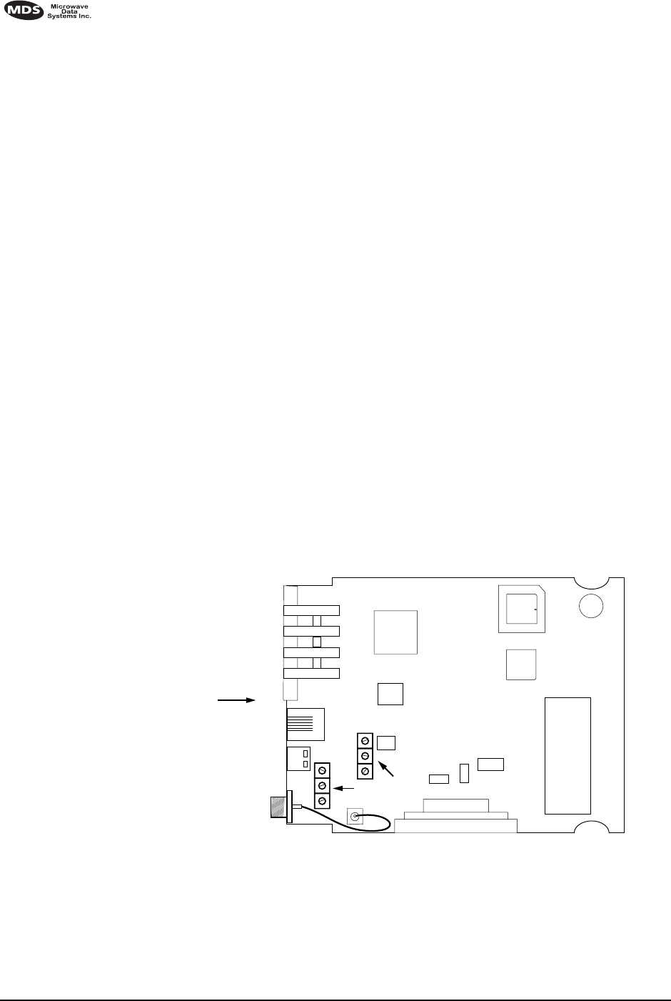
36 MDS 4710/9710 I/O Guide MDS 05-3305A01, Rev. B
7.2 Helical Filter Adjustment
If the frequency of the radio is changed more than 5 MHz, the helical
filters should be adjusted for maximum received signal strength (RSSI).
To adjust the filters, proceed as follows:
1. Remove the top cover from the transceiver by loosening the four
screws and lifting straight up.
2. Locate the helical filters on the PC board. See Figure 13.
3. Apply a steady signal to the radio at the programmed receive fre-
quency (–80 dBm level recommended; no stronger than –60 dBm).
This can be done with a signal generator or an over-the-air signal.
4. Measure the radio’s RSSI using one of the following methods:
•With an HHT (See Section 5.0, TRANSCEIVER PROGRAM-
MING on page 17).
•With MDS Radio Configuration Software (See Section 7.4,
Upgrading the Radio’s Software on page 38).
•With a voltmeter connected to Pin 21 of the DATA INTERFACE
connector (See Section 4.2, RSSI Measurement on page 16).
5. With a non-metallic adjustment tool, adjust each section of the
helical filters for maximum RSSI. Re-install the cover to the trans-
ceiver.
Invisible place holder
Figure 13. Helical Filter Locations
FRONT PANEL
OF RADIO
J301
U104
U101
U202
HELICAL
ADJUSTMENTS
U203
SHIELD
COVER
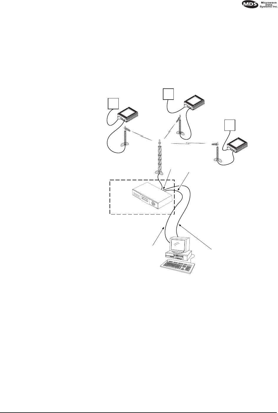
MDS 05-3305A01, Rev. B MDS 4710/9710 I/O Guide 37
7.3 Performing Network-Wide Remote Diagnostics
Diagnostics data from a remote radio can be obtained by connecting a
laptop or personal computer running MDS InSite diagnostics software
to any radio in the network. Figure 14 shows an example of a setup for
performing network-wide remote diagnostics.
Invisible place holder
Figure 14. Network-Wide Remote Diagnostics Setup
If a PC is connected to any radio in the network, intrusive polling
(polling which briefly interrupts payload data transmission) can be per-
formed. To perform diagnostics without interrupting payload data trans-
mission, connect the PC to a radio defined as the “root” radio. A radio
is defined as a root radio using the DTYPE ROOT command locally, at the
radio.
A complete explanation of remote diagnostics can be found in MDS’
Network-Wide Diagnostics System Handbook. See the Handbook for
more information about the basic diagnostic procedures outlined below.
1. Program one radio in the network as the root radio by entering the
DTYPE ROOT command at the radio.
RTU
DIAGNOSTICS DATA
(TO InSite)
HOST COMPUTER
RTU
TO
DIAGNOSTICS
PORT
TO DATA
PORT
MASTER STATION
ROOT
DTYPE
ROOT
PAYLOAD DATA
(TO SCADA APPLICATION)
RTU
DTYPE
NODE
DTYPE
NODE
DTYPE
NODE
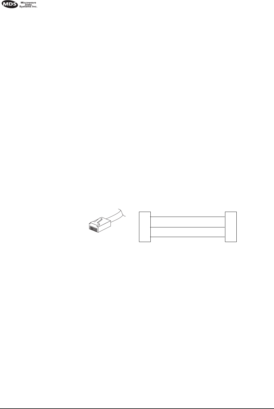
38 MDS 4710/9710 I/O Guide MDS 05-3305A01, Rev. B
2. At the root radio, use the DLINK ON and DLINK [baud rate] commands
to configure the diagnostic link protocol on the RJ-11 port.
3. Program all other radios in the network as nodes by entering the
DTYPE NODE command at each radio.
4. Use the DLINK ON and DLINK [baud rate] commands to configure the
diagnostic link protocol on the RJ-11 port of each node radio.
5. Connect same-site radios using a null-modem cable at the radios’
diagnostic ports.
6. Connect a PC on which MDS InSite software is installed to the root
radio, or to one of the nodes, at the radio’s diagnostic port. (This PC
may be the PC being used to collect payload data, as shown in
Figure 14.)
To connect a PC to the radio’s DIAG. port, an RJ-11 to DB-9 adapter
(MDS P/N 03-3246A01) is required. If desired, an adapter cable
may be constructed from scratch using the information shown in
Figure 15.
Invisible place holder
Figure 15. RJ-11 to DB-9 Adapter Cable
7. Launch the MDS InSite application at the PC. (See the MDS InSite
User’s Guide for instructions.)
7.4 Upgrading the Radio’s Software
Windows-based Radio Configuration software is available (MDS P/N
03-3156A01) for upgrading the internal radio software when new fea-
tures become available from Microwave Data Systems. Contact MDS
for ordering information.
To connect a PC to the radio’s DIAG. port, an RJ-11 to DB-9 adapter
(MDS P/N 03-3246A01) is required. If desired, an adapter cable may be
constructed from scratch using the information shown in Figure 15.
Using the Radio Configuration software, select RADIO SOFTWARE
UPGRADE under the SYSTEM menu. Follow the prompts and online
instructions to determine how to proceed.
RXD
TXD
GND
2
3
5
DB-9 FEMALE
(TO COMPUTER)
TXD
RXD
GND
4
5
6
RJ-11 PLUG
(TO RADIO)
RJ-11 PIN LAYOUT
16

MDS 05-3305A01, Rev. B MDS 4710/9710 I/O Guide 39
Software upgrades are distributed as ASCII files with a “.S28” exten-
sion. These files use the Motorola S-record format. When the download
is activated, the radio’s PWR LED will flash rapidly, confirming that a
download is in process. The download takes about two minutes.
NOTE: If a download fails, the radio is left unprogrammed and inop-
erative. This is indicated by the PWR LED flashing slowly (1
second on/1 second off). This condition is only likely if there
were to be a power failure to the computer or radio during the
downloading process. The download can be attempted again
when the fault has been corrected.

40 MDS 4710/9710 I/O Guide MDS 05-3305A01, Rev. B
7.5 dBm-Watts-Volts Conversion Chart
Table 10 is provided as a convenience for determining the equivalent
wattage or voltage of an RF power expressed in dBm.
Table 10. dBm-Watts-Volts Conversion—for 50 Ohm Systems
dBm V Po
+53 100.0 200W
+50 70.7 100W
+49 64.0 80W
+48 58.0 64W
+47 50.0 50W
+46 44.5 40W
+45 40.0 32W
+44 32.5 25W
+43 32.0 20W
+42 28.0 16W
+41 26.2 12.5W
+40 22.5 10W
+39 20.0 8W
+38 18.0 6.4W
+37 16.0 5W
+36 14.1 4W
+35 12.5 3.2W
+34 11.5 2.5W
+33 10.0 2W
+32 9.0 1.6W
+31 8.0 1.25W
+30 7.10 1.0W
+29 6.40 800mW
+28 5.80 640mW
+27 5.00 500mW
+26 4.45 400mW
+25 4.00 320mW
+24 3.55 250mW
+23 3.20 200mW
+22 2.80 160mW
+21 2.52 125mW
+20 2.25 100mW
+19 2.00 80mW
+18 1.80 64mW
+17 1.60 50mW
+16 1.41 40mW
+15 1.25 32mW
+14 1.15 25mW
+13 1.00 20mW
+12 .90 16mW
+11 .80 12.5mW
+10 .71 10mW
+9 .64 8mW
+8 .58 6.4mW
+7 .500 5mW
+6 .445 4mW
+5 .400 3.2mW
+4 .355 2.5mW
+3 .320 2.0mW
+2 .280 1.6mW
+1 .252 1.25mW
dBm V Po
0 .225 1.0mW
-1 .200 .80mW
-2 .180 .64mW
-3 .160 .50mW
-4 .141 .40mW
-5 .125 .32mW
-6 .115 .25mW
-7 .100 .20mW
-8 .090 .16mW
-9 .080 .125mW
-10 .071 .10mW
-11 .064
-12 .058
-13 .050
-14 .045
-15 .040
-16 .0355
dBm mV Po
-17 31.5
-18 28.5
-19 25.1
-20 22.5 .01mW
-21 20.0
-22 17.9
-23 15.9
-24 14.1
-25 12.8
-26 11.5
-27 10.0
-28 8.9
-29 8.0
-30 7.1 .001mW
-31 6.25
-32 5.8
-33 5.0
-34 4.5
-35 4.0
-36 3.5
-37 3.2
-38 2.85
-39 2.5
-40 2.25 .1µW
-41 2.0
-42 1.8
-43 1.6
-44 1.4
-45 1.25
-46 1.18
-47 1.00
-48 0.90
dBm mV Po
-49 0.80
-50 0.71 .01µW
-51 0.64
-52 0.57
-53 0.50
-54 0.45
-55 0.40
-56 0.351
-57 0.32
-58 0.286
-59 0.251
-60 0.225 .001µW
-61 0.200
-62 0.180
-63 0.160
-64 0.141
dBm µV Po
-65 128
-66 115
-67 100
-68 90
-69 80
-70 71 .1nW
-71 65
-72 58
-73 50
-74 45
-75 40
-76 35
-77 32
-78 29
-79 25
-80 22.5 .01nW
-81 20.0
-82 18.0
-83 16.0
-84 11.1
-85 12.9
-86 11.5
-87 10.0
-88 9.0
-89 8.0
-90 7.1 .001nW
-91 6.1
-92 5.75
-93 5.0
-94 4.5
-95 4.0
-96 3.51
-97 3.2
dBm µV Po
-98 2.9
-99 2.51
-100 2.25 .1pW
-101 2.0
-102 1.8
-103 1.6
-104 1.41
-105 1.27
-106 1.18
dBm nV Po
-107 1000
-108 900
-109 800
-110 710 .01pW
-111 640
-112 580
-113 500
-114 450
-115 400
-116 355
-117 325
-118 285
-119 251
-120 225 .001pW
-121 200
-122 180
-123 160
-124 141
-125 128
-126 117
-127 100
-128 90
-129 80 .1ƒW
-130 71
-131 61
-132 58
-133 50
-134 45
-135 40
-136 35
-137 33
-138 29
-139 25
-140 23 .01ƒW

MDS 05-3305A01, Rev. B MDS 4710/9710 I/O Guide 41
NOTES

42 MDS 4710/9710 I/O Guide MDS 05-3305A01, Rev. B

MDS 05-3305A01, Rev. B MDS 4710/9710 I/O Guide I-1
INDEX
A
ACCESS DENIED error message 20
Accessories 4
Accessory Power pinout (Pin 18) 15
Active messaging (defined) 6
Alarms
alarm code definitions 32
major vs. minor 32
pinout (Pin 25) 15
using STAT command to display 29
AMASK command 22
Antenna
installation 9
RSSI command used to refine heading 15
system gain, defined 6
Yagi, illustrated 12
Antennas 11–12
Applications 2
Multiple Address Systems (MAS) 2
point-to-multipoint system 2
point-to-point system 3
ASENSE command 23
B
BAUD command 23
Baud rate
setting for RJ-11 DIAG port (DLINK command) 25, 38
Bit, defined 6
Bits-per-second. See BPS 6
BPS (bits-per-second), defined 6
BUFF command 24
Byte, defined 6
C
Cable, loss due to length of coaxial at 400 MHz 12
Cable, loss due to length of coaxial at 960 MHz 12
Cautions
use attenuation between all units in test setup 37
CKEY command 24
COMMAND FAILED error message 20
Command summary, table 20
Commands
AMASK (set/display alarm triggers) 22
ASENSE (set alarm output state) 23
BAUD (set/display rate, encoding) 23
BUFF (set/display data handling mode) 24
CKEY (enable/disable continuous keying) 24
CTS (set/display CTS line response timer) 24
DATAKEY (enable/disable transmitter keying by radio) 24
descriptions 22–30
DEVICE (set/display radio behavior) 25
DKEY (deactivate transmitter after KEY command) 25
DLINK (enable/disable network-wide diagnostics) 25
DMGAP (set time to wait between characters) 25
DTYPE (set radio to root or node for diagnostics) 26
DUMP (display all programmed settings) 26
entering on Hand-Held Terminal (HHT) 19
Hand-Held Terminal (HHT) 19
HREV (display hardware revision level) 26
INIT (reinitialize radio to factory defaults) 26
INIT xx10 (restore standard transceiver defaults) 26
INIT xx20 (configure radio for use with P-20 chassis) 27
KEY (activate transmitter) 27
MODEL (display radio model number code) 27
MODEM (set modem speed) 27
OWM (set/display owner’s message) 27
OWN (set/display owner’s name) 27
PTT (set/display key-up delay) 27
PWR (set/display RF forward output power) 27
RSSI (display RSSI) 28
RTU (enable/disable internal RTU) 28
RX (set/display receive frequency) 28
RXTOT (set/display receive time-out timer value) 28
SCD (set/display soft-carrier dekey delay) 29
SER (display radio serial number 29
SHOW (display DC voltage, data port, RF power) 29
SNR (display signal-to-noise ratio) 29
SREV (display software revision level) 29
STAT (display current alarm status) 29
TEMP (display internal temperature) 30
TOT (set/display time-out value and timer status) 30
TX (set/display transmit frequency) 30
Conversions, dBm-Watts-Volts 40
CTS command 24
CTS pinout (Pin 5) 14
D
Data interface
connector pinouts 14
display active connector port 29
installing connection 13
DATAKEY command 24
dB. See Decibel 6
dBi, defined 6
dBm, defined 6
DCD
LED 16
pinout (Pin 8) 14
DCE (Data Cirtuit-terminating Equipment), defined 6

I-2 MDS 4710/9710 I/O Guide MDS 05-3305A01, Rev. B
Decibel (dB), defined 6
Description, product 1
DEVICE command 25
Diagnostic Channel Enable, pinout (Pin 23) 15
Diagnostics
interface specifications 35
network-wide, performing 37
PC software used for 38
using InSite software for network-wide 37
Display
alarm status (STAT command) 29
alarm triggers (AMASK command) 22
all programmed settings (DUMP command) 26
baud rate and encoding (BAUD command) 23
connector port, active (SHOW command) 29
CTS line response timer (CTS command) 24
data handling mode (BUFF command) 24
DC voltage (SHOW command) 29
hardware revision leve (HREV command)l 26
key-up delay (PTT command) 27
model number code (MODEL command) 27
owner’s message (OWM command) 27
owner’s name (OWN command) 27
radio behavior (DEVICE command) 25
radio serial number (SER command) 29
receive frequency (RX command) 28
receive time-out timer value (RXTOT command) 28
RF forward output power (PWR command) 27
RF output (SHOW command) 29
RSSI (RSSI command) 28
signal-to-noise ratio (SNR command) 29
soft-carrier dekey delay (SCD command) 29
software revision level (SREV command) 29
temperature, internal (TEMP command) 30
time-out value and timer status (TOT command) 30
transmit frequency (TX command) 30
DKEY command 25
DLINK command 25
use of 38
DMGAP command 25
Downloading new software 38
DSP (Digital Signal Processing), defined 7
DSR pinout (Pin 6) 14
DTE (Data Terminal Equipment), defined 7
DTYPE command 26
use of 37
DUMP command 26
E
EEPROM FAILURE error message 20
Enable/disable
continuous keying (CKEY command) 24
diagnostic channel, pinout (Pin 23) 15
internal RTU (RTU command) 28
network-wide diagnostics (DLINK command) 25
network-wide diagnostics, procedures 38
Environment specifications 35
Equalization, defined 7
Error messages 19
access denied 20
command failed 20
EEPROM failure 20
incorrect entry 19
not available 20
not programmed 20
text too long 20
unknown command 19
F
Fade margin, defined 7
Feedlines 12
Filter, helical, adjustment 36
Frame, defined 7
Frequency
adjusting helical filter when changed 36
setting. See TX and RX commands
G
Glossary 6
Ground
on Pin 12 to enable Sleep mode 14
protective (Pin 1) 14
signal (Pin 7) 14
H
Half-duplex 3
switched carrier operation 3
Hand-Held Terminal (HHT) 5
connected to transceiver, illustrated 18
connection and startup 17
display in response to STAT command, illustrated 31
entering commands 19
error messages displayed on 19
keyboard commands 19
operational settings, table 19
reinitialization display, illustrated 18
reinitializing 18
Hardware flow control, defined 7
Helical filter
adjusting 36
illustration 36
Host computer, defined 7
HREV command 26
I
Illustrations
4710A model number codes 4
9710A model number codes 4
antenna, Yagi 12
Hand-Held Terminal (HHT) connected to transceiver 18
Hand-Held Terminal (HHT) reinitialization display 18
Hand-Held Terminal display in response to STAT command 31

MDS 05-3305A01, Rev. B MDS 4710/9710 I/O Guide I-3
helical filter locations 36
MAS network 2
network-wide diagnostics 37
point-to-point link 3
remote station arrangement 9
RJ-11 to DB-9 adapter cable 38
RSSI vs. Vdc 13, 16
transceiver connectors & indicators 1
transceiver mounting dimensions 11
INCORRECT ENTRY error message 19
INIT command 26
INIT xx10 command 26
INIT xx20 command 27
InSite software
using to perform remote diagnostics 37
Installation 9–15
antenna 9
configuring transceiver 10
DATA INTERFACE connection 9
data interface connections 13
power 10
power connection 13
steps 9
Intrusive diagnostics (defined) 7
K
KEY command 27
Keying
continuously keyed versus switched carrier operation 3
continuously keyed, defined 3
on data (DKEY command) 25
switched carrier, defined 3
L
Latency, defined 7
LEDs
DCD 16
indicators, described 16
PWR 16
RXD 16
RXD, Pin 3 14
status indicators, illustrated 16
TXD 16
TXD, Pin 2 14
Loss. See Signal
M
MAS (Multiple Address System) 2
defined 7
illustration 2
Master Station
defined 7
keying behavior 3
MCU (Microcontroller Unit), defined 7
MODEL command 27
Model number codes 3
4710A, illustrated 4
9710A, illustrated 4
displaying (MODEL command) 27
MODEM command 27
Modem, set speed. See MODEM command
N
Network-wide diagnostics
active messaging, defined 6
defined 8
enable/disable (DLINK command) 25
enable/disable internal RTU (RTU command) 28
illustrated 37
intrusive diagnostics, defined 7
passive messaging (defined) 8
procedures 37
set radio to root or node (DTYPE command) 26
set time to wait between characters (DMGAP command) 25
NOT AVAILABLE error message 20
NOT PROGRAMMED error message 20
O
Operation 15–16
environment specifications for 35
Output, 9.9 Vdc regulated, pinout (Pin 19) 15
OWM command 27
OWN command 27
Owner’s message, set/display. See OWM command
Owner’s name, set/display. See OWN command
P
Passive messaging (defined) 8
Payload data (defined) 8
Pinouts on data interface 14
PLC (Programmable Logic Controller), defined 8
Point-to-multipoint
defined 8
system 2
Point-to-point
link, illustrated 3
system 3
Poll, defined 8
Power
connection 13
display DC voltage (SHOW command) 29
display RF output (SHOW command) 29
installing 10
LED status indicator (PWR LED) 16
RF, chart for converting dBm-Watts-Volts 40
specifications 35
Procedures
checking for alarms (STAT command) 31
connecting Hand-Held Terminal (HHT) 17
downloading new software 38
entering commands using the Hand-Held Terminal (HHT) 19
helical filter adjustment 36

I-4 MDS 4710/9710 I/O Guide MDS 05-3305A01, Rev. B
installation 9
measuring RSSI with DC voltmeter 16
network-wide diagnostics 37
operation 15, 16
performance optimization 15
reading LED status indicators 16
resetting Hand-Held Terminal (HHT) 18
troubleshooting 30–33
Product
accessories 4
description 1
display model number code (MODEL command) 27
display radio serial number (SER command) 29
model number codes 3
Programming radio as root or node 37
Programming, transceiver 17–30
PTT
command 27
pinout (Pins 14, 16) 14
PWR
command 27
LED 16
R
Radio
Configuration Software 5, 38
Inhibit pinout (Pin 12) 14
serial number, displaying (SER command) 29
Receive Audio Output pinout (Pin 11) 14
Receiver
specifications 34
system specifications 33
unsquelched signal (Pin 10) 14
Redundant operation, defined 8
Remote
RTU reset (Pin 15) 15
Station, defined 8
Station, illustrated 9
Resetting
Hand-Held Terminal (HHT) (SHIFT,CTRL,SPACE keys) 18
remote RTU reset (Pin 15) 15
transceiver (INIT command) 26
Revision level
display hardware (HREV command) 26
display software (SREV command) 29
RSSI
adjusting helical filter for increased signal strength 36
command 28
command, used to refine antenna heading 15
measuring 16
pinout (Pin 21) 15
vs. Vdc, illustrated 13, 16
RTS pinout (Pin 4) 14
RTU
command 28
RTU (Remote Terminal Unit)
defined 8
remote reset (Pin 15) 15
RUS pinout (Pin10) 14
RX command 28
RXD LED
description 16
Pin 3 14
RXTOT command 28
S
SCADA (Supervisory Control And Data Acquisition), defined 8
SCD command 29
SER command 29
Set
alarm output state (ASENSE command) 23
alarm triggers (AMASK command) 22
receive time-out timer value (RXTOT command) 28
SHOW command 29
Signal
ground (Pin 7) 14
loss due to coaxial cable length at 960 MHz, table 12
loss due to coaxial cable length, table 12
Simplex 3
single-frequency operation 3
special case of switched carrier operation 3
Sleep mode
example implementation 13
ground on Radio Inhibit pin activates 14
Pin 12 14
shown by PWR LED status indicator 16
SNR command 29
Software
diagnostics and control used from PC 38
display revision level 29
upgrades (.S28 files) 39
upgrading 38
used for diagnostics and programming 17
Specifications
diagnostics interface 35
environment 35
power 35
receiver 34
receiver system 33
transceiver 33–35
transmitter 34
transmitter system 33
SREV command 29
STAT command 29
SWR (Standing Wave Radio), defined 8
T
Tables
accessories 5
alarm code definitions 32
command summary 20
conversions, dBm-Watts-Volts 40
data interface connector pinouts 14
Hand-Held Terminal (HHT) operational settings 19
LED status indicators 16
length vs. loss in coaxial cables 12

MDS 05-3305A01, Rev. B MDS 4710/9710 I/O Guide I-5
length vs. loss in coaxial cables at 960 MHz 12
Technical reference 33–40
TEMP command 30
Temperature, displaying internal (TEMP command) 30
TEXT TOO LONG error message 20
Timer, set/display time-out value and status (TOT command) 30
TOT command 30
Transceiver
applications 2
configuring for operation 10
connectors and indicators, illustrated 1
diagnostics using PC software 38
dimensions, mounting 11
mounting 9, 11
programming 17–30
specifications 33–35
upgrading software 38
Transmit Audio Input pinout (Pin 9) 14
Transmitter
specifications 34
system specifications 33
Troubleshooting 30–33
connecting Hand-Held Terminal (HHT) for displaying alarm
codes 17
performing network-wide diagnostics 37
STAT command (Status) 31
using PC software for 38
TX command 30
TXD LED
description 16
Pin 2 14
U
UNKNOWN COMMAND error message 19

I-6 MDS 4710/9710 I/O Guide MDS 05-3305A01, Rev. B

IN CASE OF DIFFICULTY...
Our products are designed for long life and trouble-free operation. However, this equipment, as with all
electronic equipment may have an occasional component failure. The following information will assist you
in the event that servicing becomes necessary.
FACTORY TECHNICAL ASSISTANCE
Technical assistance for our products is available from our Customer Support Team during business hours
(8:00 A.M.–5:30 P.M. Eastern Time). When calling, please give the complete model number of the radio,
along with a description of the trouble symptom(s) that you are experiencing. In many cases, problems can
be resolved over the telephone, without the need for returning the unit to the factory.
Please use the following telephone numbers for product assistance:
716-242-9600 (Phone)
716-242-9620 (FAX)
FACTORY REPAIRS
Component-level repair of radio equipment is not recommended in the field. Many components are
installed using surface mount technology, which requires specialized training and equipment for proper
servicing. For this reason, the equipment should be returned to the factory for any PC board repairs. The
factory is best equipped to diagnose, repair and align your radio to its proper operating specifications.
If return of the equipment is necessary, you will be issued a Returned Material Authorization (RMA)
number. The RMA number will help expedite the repair so that the equipment can be repaired and returned
to you as quickly as possible. Please be sure to include the RMA number on the outside of the shipping
box, and on any correspondence relating to the repair. No equipment will be accepted for repair without
an RMA number.
A statement should accompany the radio describing, in detail, the trouble symptom(s), and a description
of any associated equipment normally connected to the radio. It is also important to include the name and
telephone number of a person in your organization who can be contacted if additional information is
required.
The radio must be properly packed for return to the factory. The original shipping container and packaging
materials should be used whenever possible. All factory returns should be addressed to:
When repairs have been completed, the equipment will be returned to you by the same shipping method
used to send it to the factory. Please specify if you wish to make different shipping arrangements.
Microwave Data Systems Inc.
Customer Service Department
(RMA No. XXXX)
175 Science Parkway
Rochester, NY 14620 USA

175 Science Parkway, Rochester, New York 14620
General Business: +1 (716) 242-9600
FAX: +1 (716) 242-9620
Web: www.microwavedata.com