GE MDS INET900 MDS iNet 900 User Manual 2873F iNet Body
GE MDS LLC MDS iNet 900 2873F iNet Body
UserManual.wiki
>
GE MDS
>
INET900 User Manual
>
users manual
Contents
1.
users manual
2.
installation guide
users manual
Navigation menu
Upload a User Manual
Namespaces
Wiki Guide
HTML
PDF
Info
Views
User Manual
Discussion / Help
Navigation

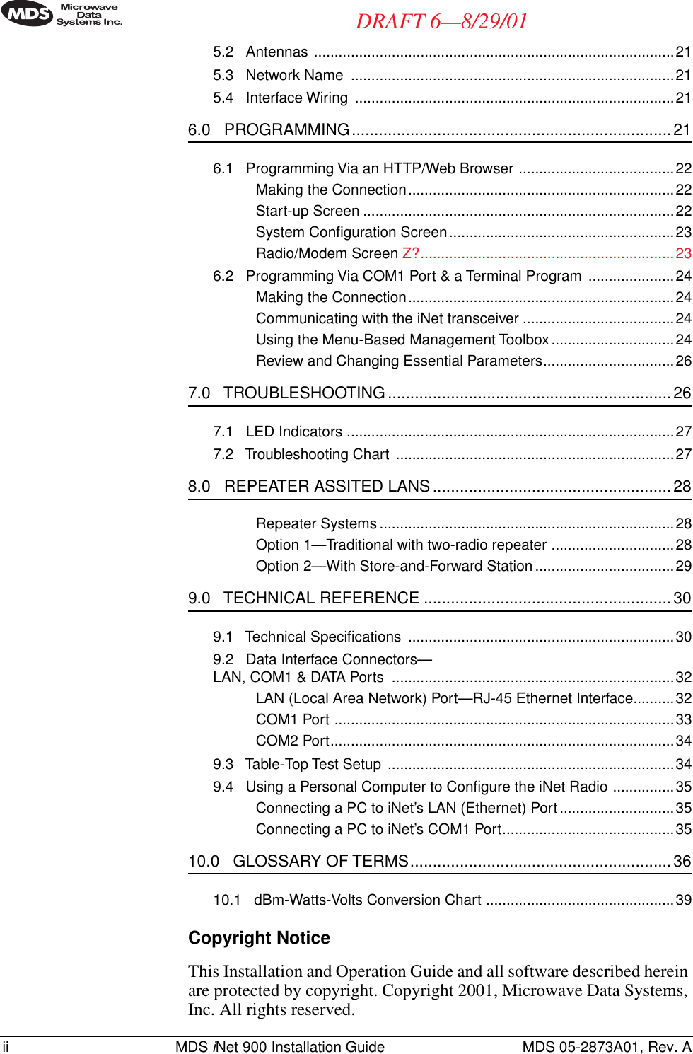
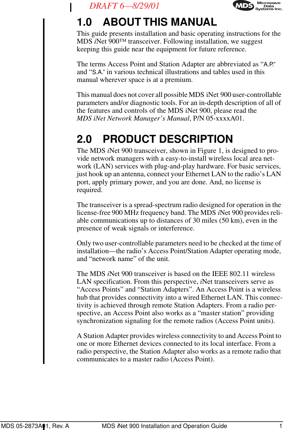
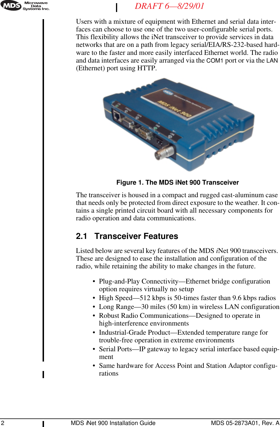
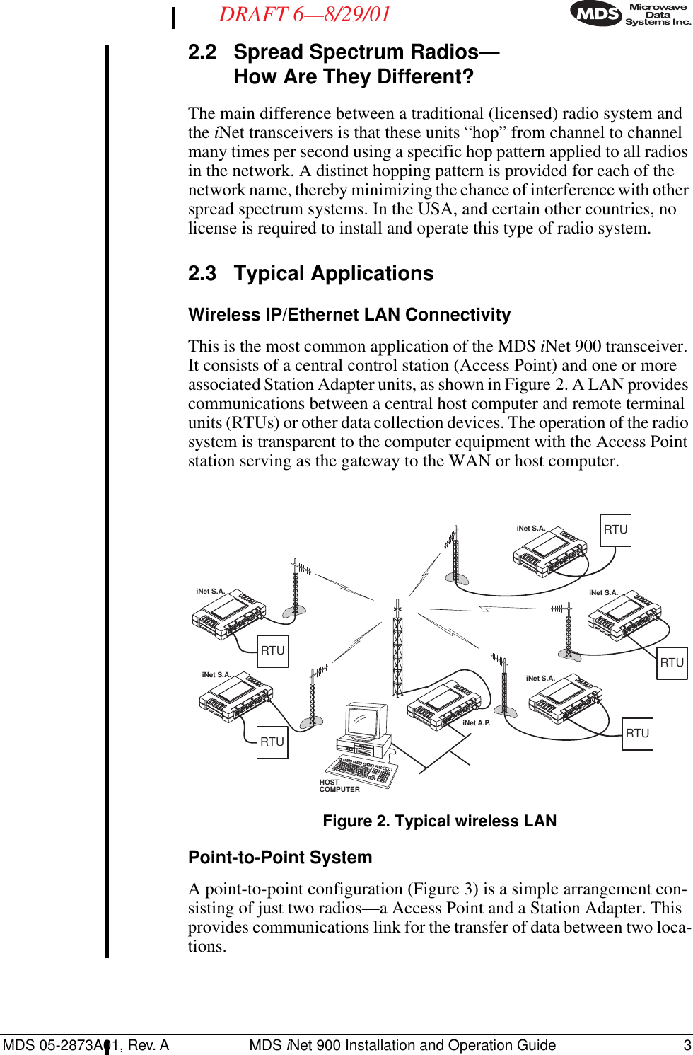
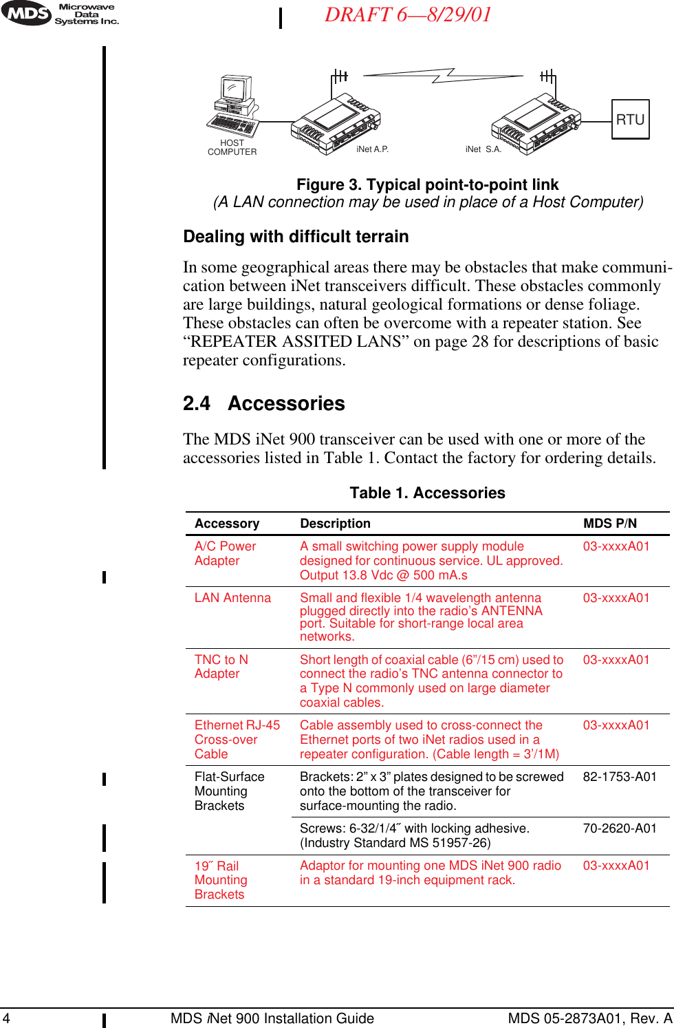
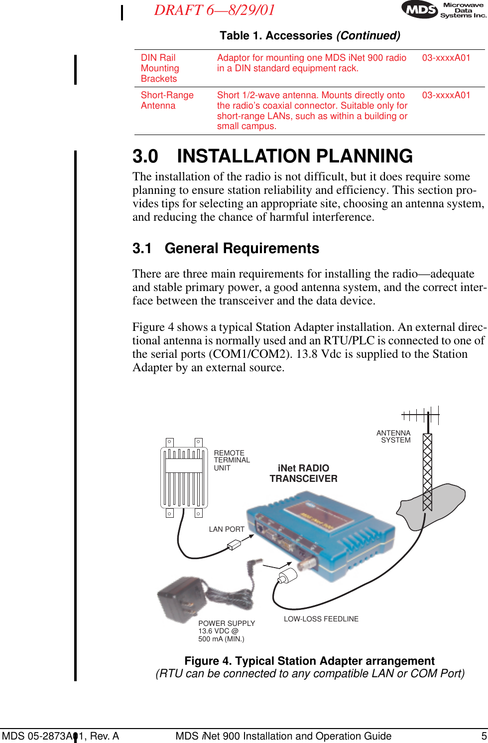
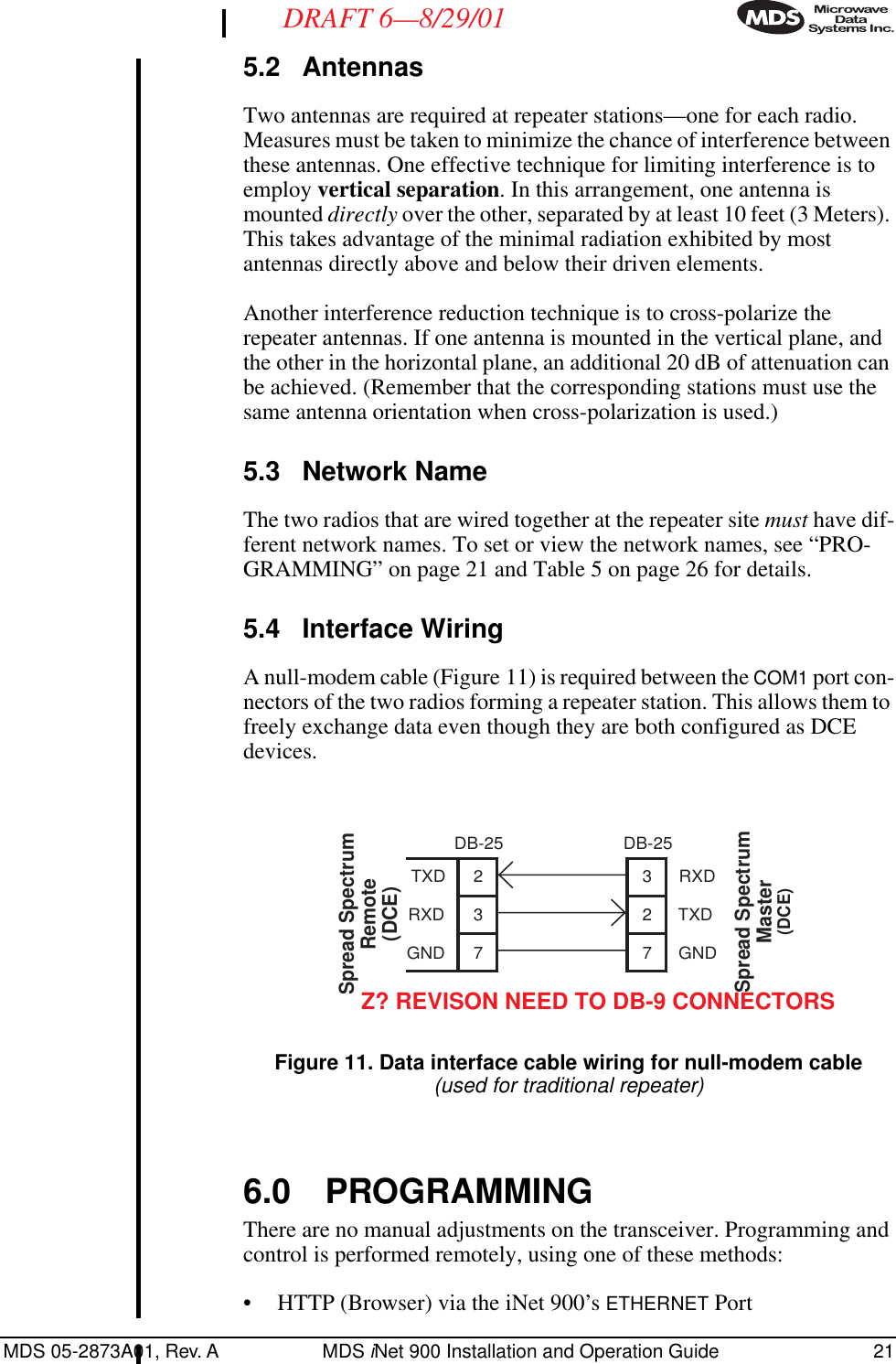
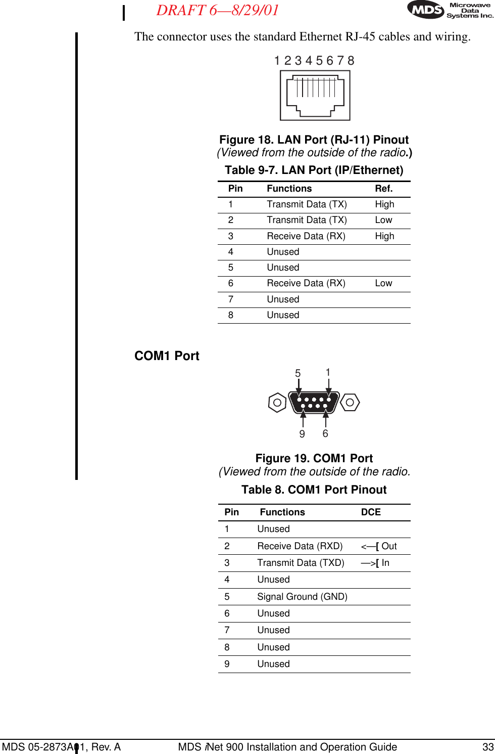
![34 MDS iNet 900 Installation Guide MDS 05-2873A01, Rev. ADRAFT 6—8/29/01COM2 PortFigure 20. COM2 PortViewed from the outside of the radio9.3 Table-Top Test SetupIt may be convenient to set up table-top network that can be used to verify the basic operation of the MDS iNet 900 transceivers and give you a chance to experiment with network designs, configurations or net-work equipment in a convenient location. This test can be performed with any number of MDS iNet 900 radios.To simulate data traffic over the radio network, connect a PC or LAN to the Ethernet port of each radio. One of the MDS iNet 900 transceivers in this mini-network must be set to the Access Point Mode for proper operation.NOTE: It is very important to use a “Network Name” that is different from ones currently in use in your area during the testing period. This will eliminate unnecessary traffic on the existing network while you become familiar with the MDS iNet 900 transceivers or evaluate variations of unit operating parame-ters. Use any convenient antenna that can be connected to the transceiver’s TNC connector. You may purchase a flexible one-quarter wavelength antennas from Microwave Data Systems. (P/N xx-xxxxAxx)5169Table 9. COM2 Port (DTE/DCE1)(DB-9/RS-232 Interface, Output: Out ]–>, Input: In [<– )Pin Functions DTE1 Data Carrier Detect (DCD) In ]<—2 Receive Data (RXD) In ]<—3 Transmit Data (TXD) Out ]—>4 Data Terminal Ready (DTR) Out ]—>5 Signal Ground (GND)6 Data Set Ready (DSR) In ]<—7 Request-to-Send (RTS) Out ]—>8 Clear-to-Send (CTS) In ]<—9Unused1. Default = DTE; User configurable to DCE](https://usermanual.wiki/GE-MDS/INET900.users-manual/User-Guide-223464-Page-42.png)