GE MINING AUSTRALIA PROD08422 Collision Avoidance System User Manual CASLITE Installation Manual

GE MINING AUSTRALIA Collision Avoidance System CASLITE Installation Manual

Contents

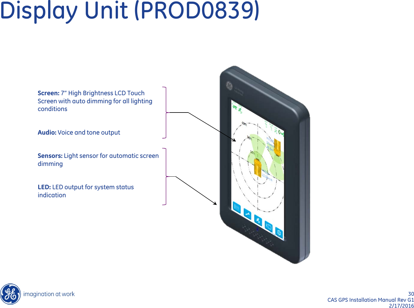
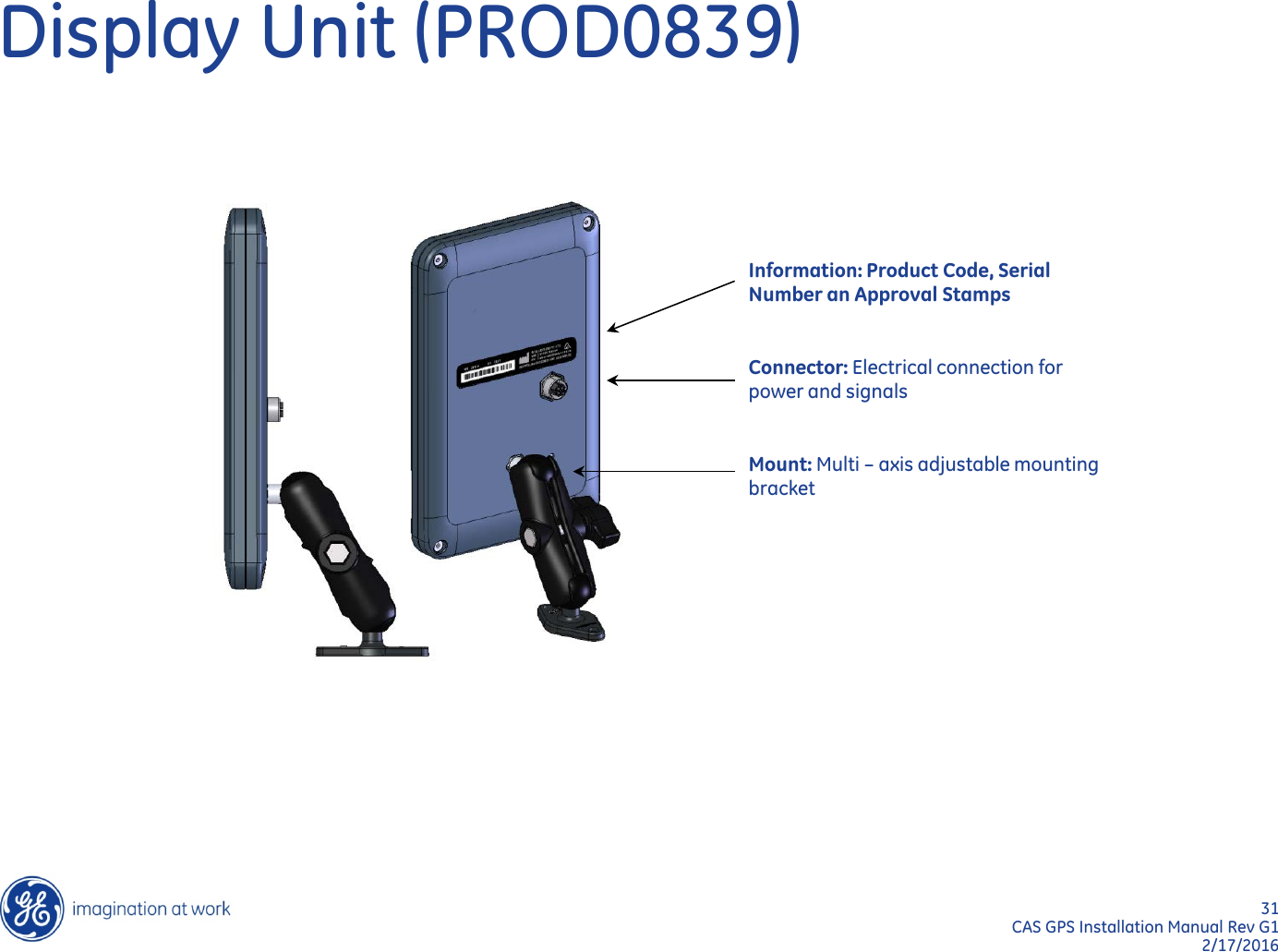
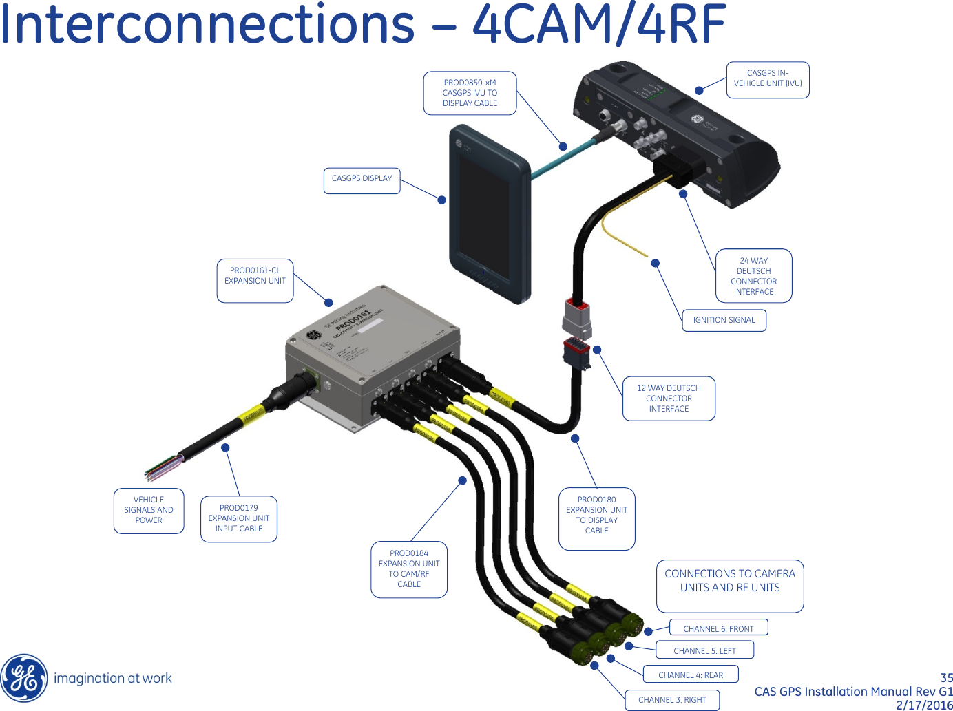
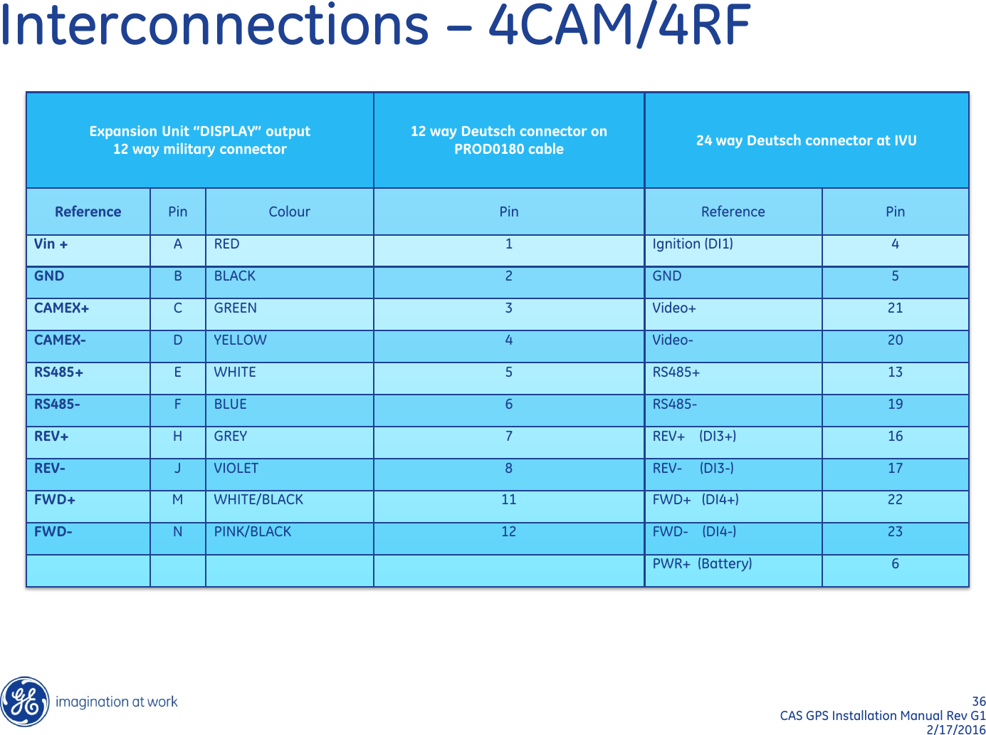
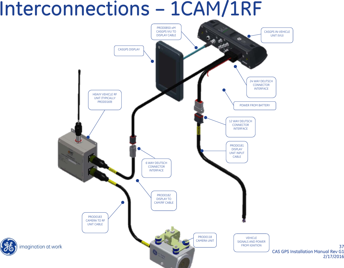
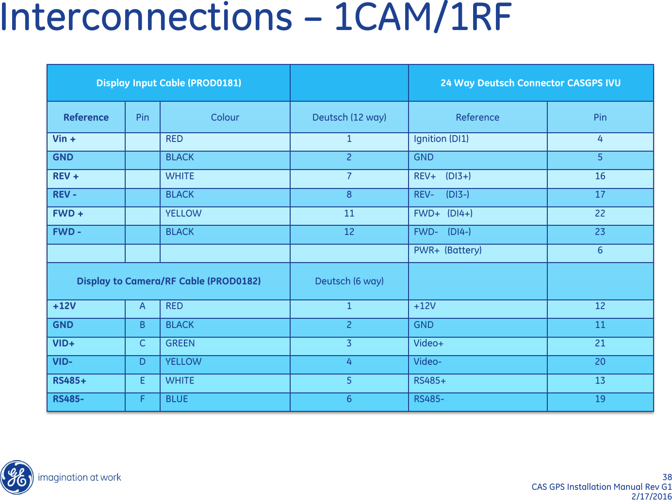
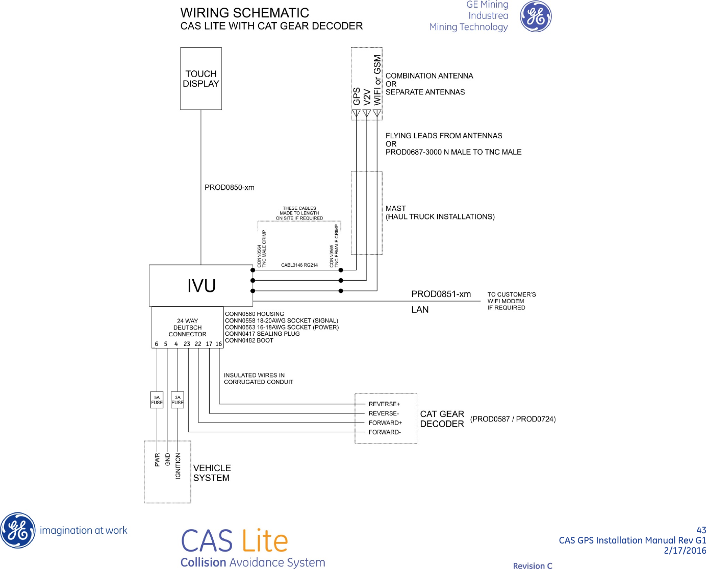
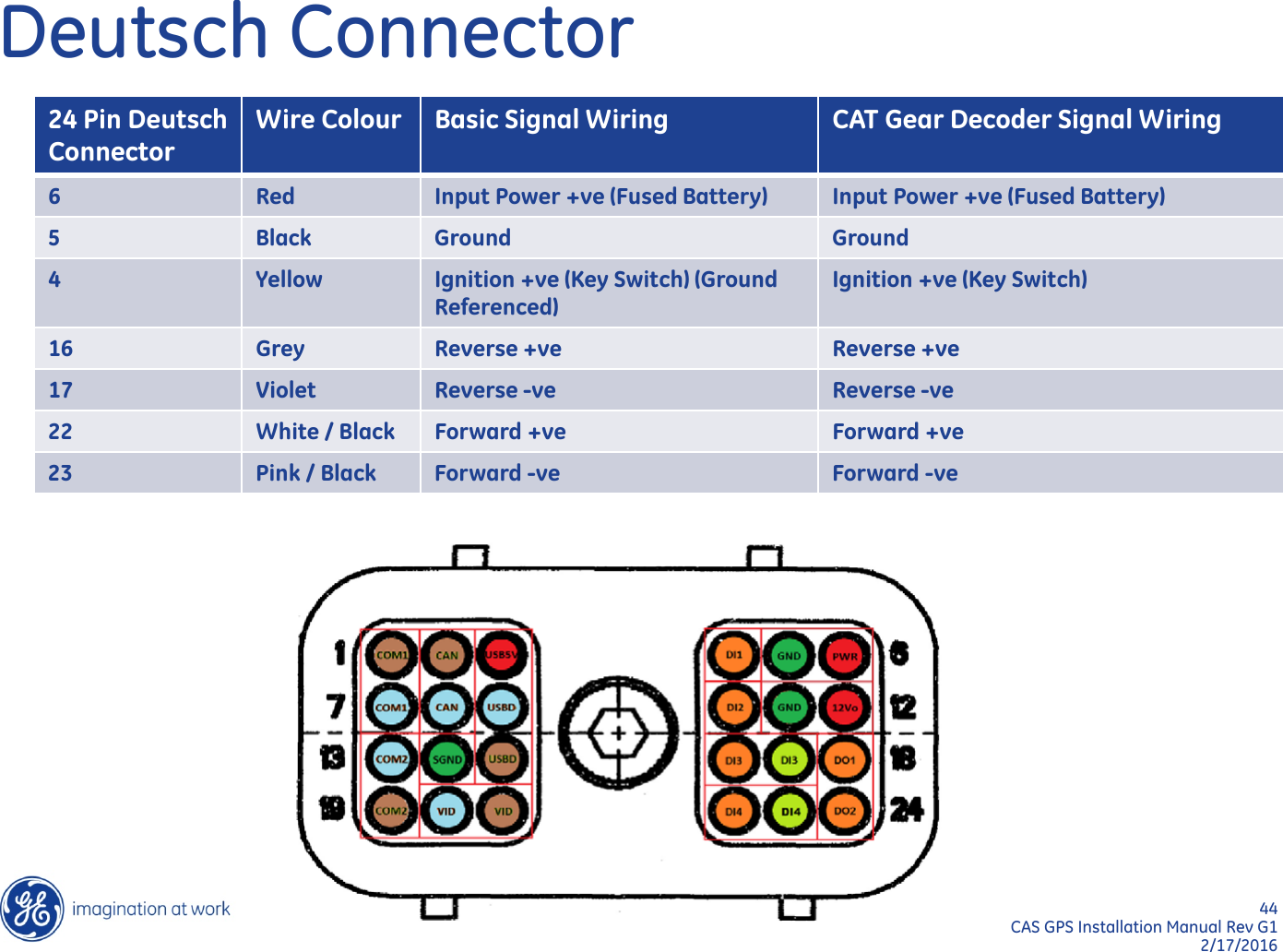
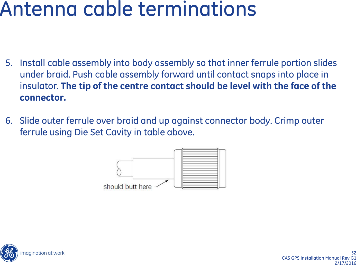
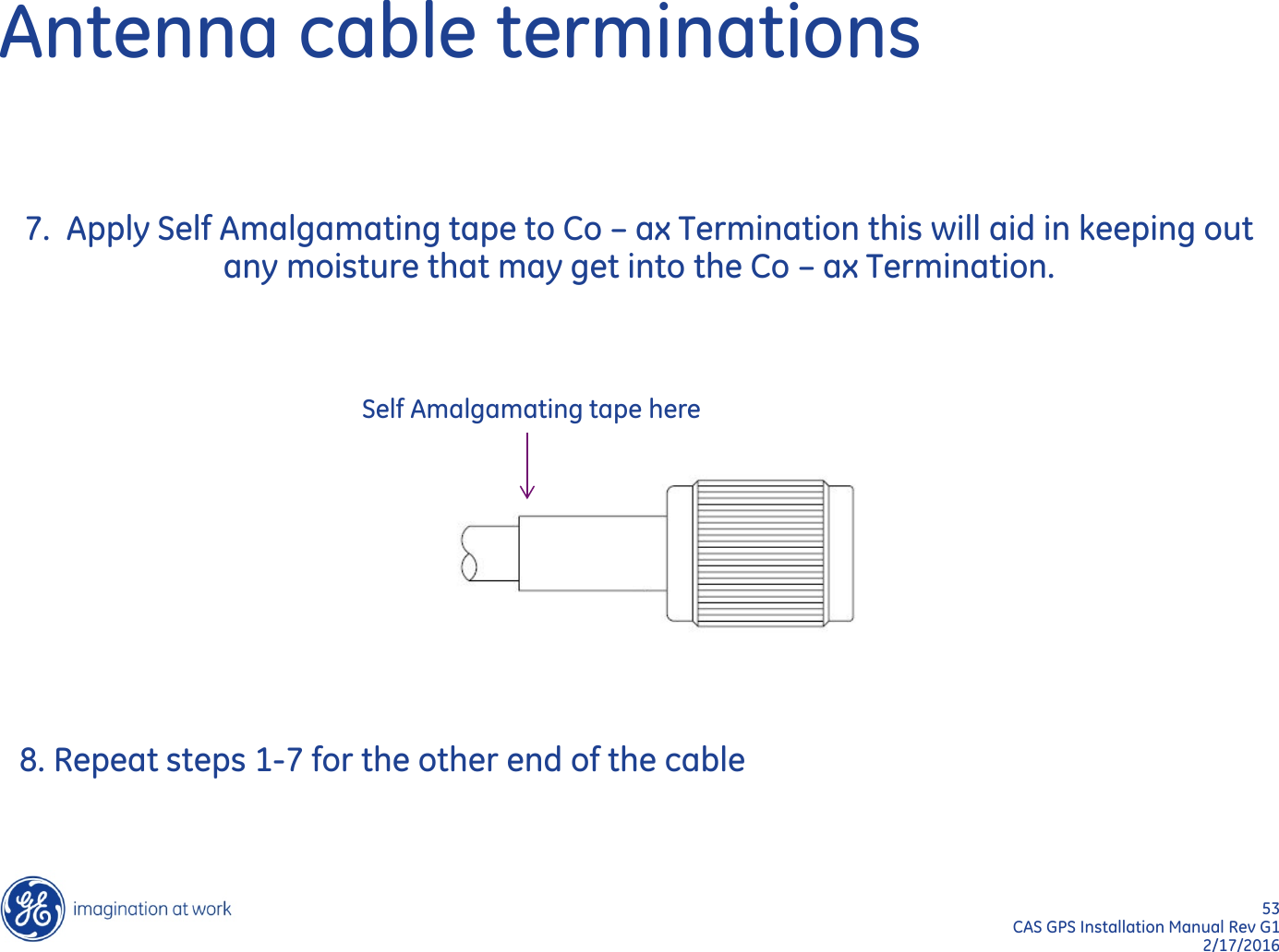
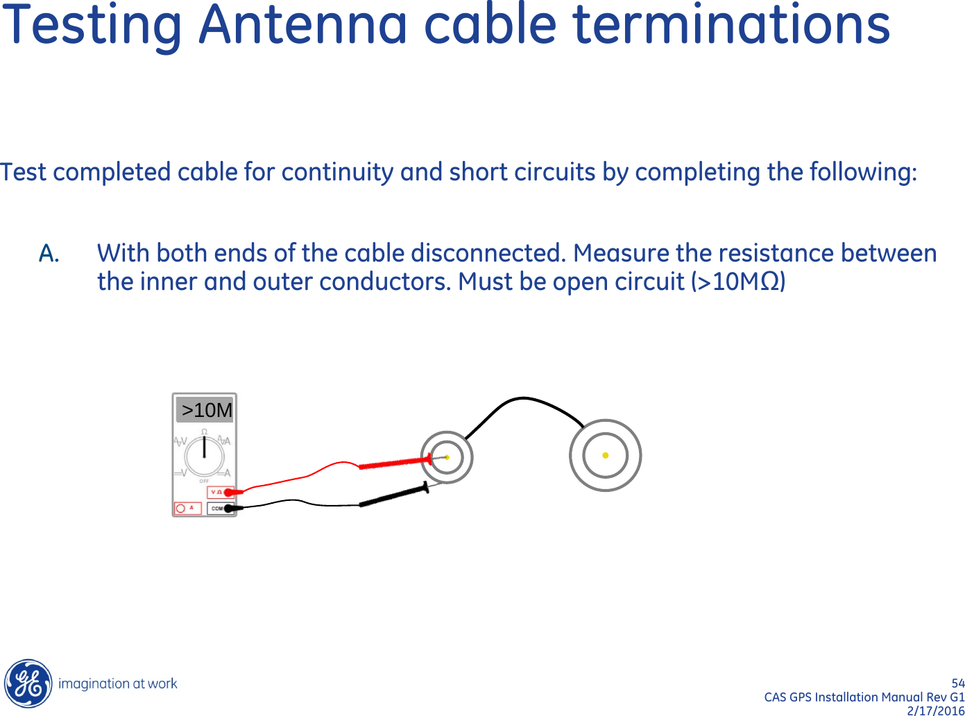
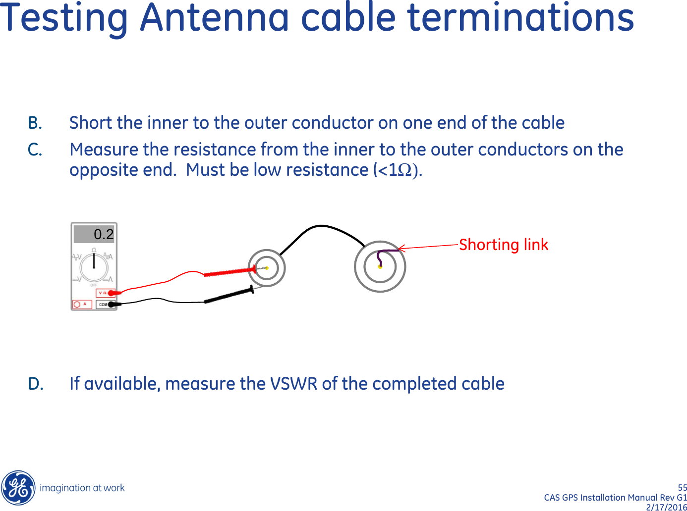
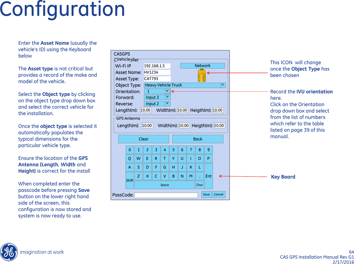
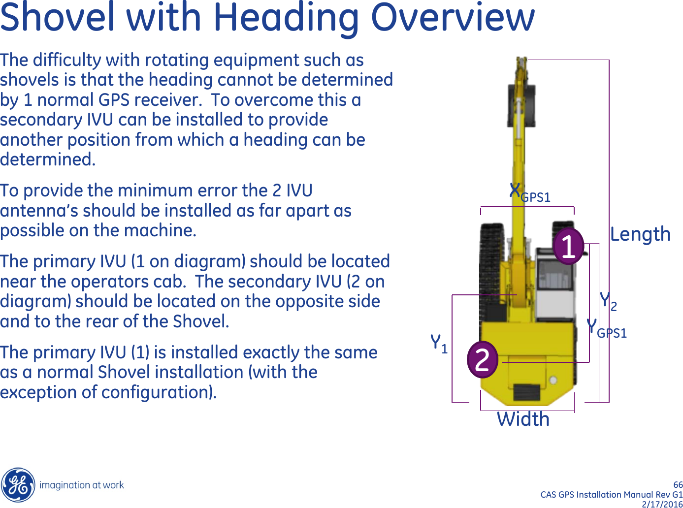
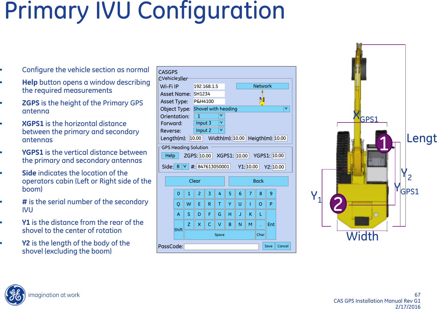
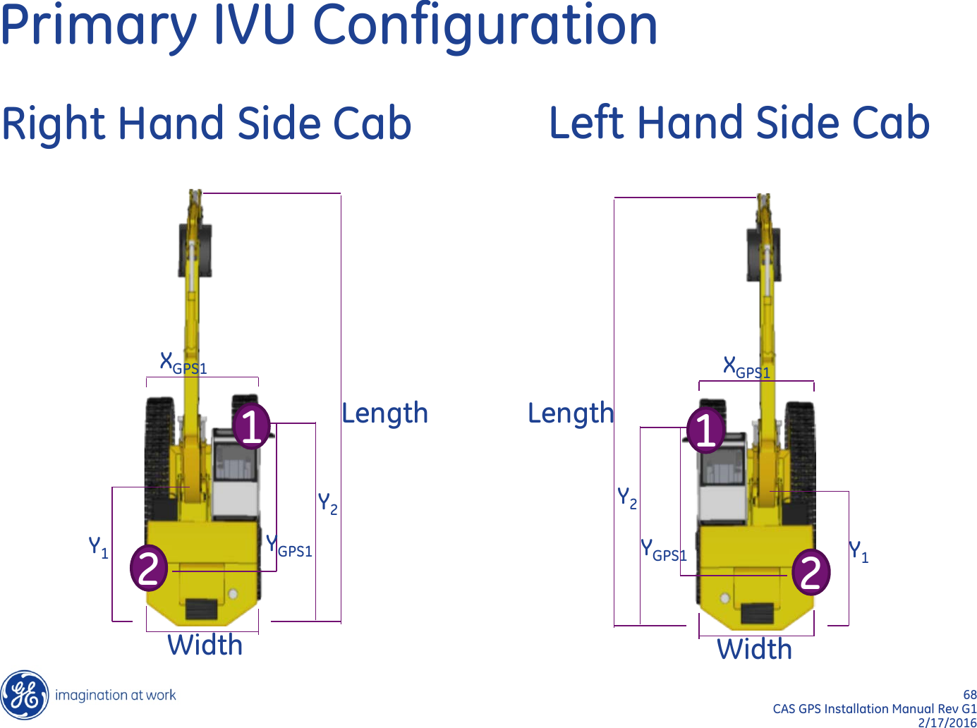
User Manual_20160322_v1 - CAS GPS Installation Manual RevG1 160323.pdf

             Installation Manual Rev G1         GE Mining Industrea Mining Technology PO Box 5107 Fountaindale, New South Wales Australia, 2258 Tel: +61 2 4336 1800 Fax: +61 2 4336 1888 Email: EnquiriesIMT@geindustrea.ge.com Web: www.ge.com/au      CAS GPS  Collision Avoidance System
2  CAS GPS Installation Manual Rev G1 2/17/2016 Document Control REV DESCRIPTION Review Approval Date E  Added shovel heading   19/11/2014 F  Fixed inconsistent pinouts on 24way connector  27/03/2015 G  Added Compliant Antenna Information (Page 6) D.Mc  19/11/2015
3  CAS GPS Installation Manual Rev G1 2/17/2016 Transport All possible precautions are taken to protect the equipment against damage or losses during shipment, however before accepting delivery, check all items against the packing list or bill of loading. If there are shortages or evidence of physical damage, notify GE Mining immediately. Notify GE Mining within 7 days (maximum) in case of shortages or discrepancies, according to the packing list. This will help ensure a speedy resolution to any perceived problems. Keep a record of all claims and correspondence. Photos are recommended. Where practicable do not remove protective covers prior to installation unless there are indications of damage. Boxes opened for inspection and inventory should be carefully repacked to ensure protection of the contents or else the parts should be packaged and stored in a safe place. Examine all packing boxes, wrappings and covers for items attached to them, especially if the wrappings are to be discarded.
4  CAS GPS Installation Manual Rev G1 2/17/2016 Storage Where the equipment is not to be installed immediately, proper storage is important to ensure protection of equipment and validity of warranty.  Storage  Temperature: -30 deg C to +85 deg C Storage Location:   dry low humidity location
5  CAS GPS Installation Manual Rev G1 2/17/2016 Unpacking of Equipment The method of packing used will depend on the size and quantity of equipment. Take care when unpacking the equipment to avoid damage to the equipment and ensure the use of correct manual handling techniques.
6  CAS GPS Installation Manual Rev G1 2/17/2016 Installation Installation should be in accordance with the installation procedures defined by GE Mining and only performed by authorised and qualified installers. This device has been designed to operate with the antennas listed below, and having a maximum gain listed. Antennas not included in this list or having a gain greater than those listed are strictly prohibited for use with this device. The required antenna impedance is 50ohms.   GE Part# Relevant Product  (x = any variant) CAS-GPS Port Nominal Impedance Gain Operating Frequency PROD0852  PROD084x-2  V2V 50 Ω  +4dBi  902-928MHz PROD0874  PROD084x-1  V2V 50 Ω  +4dBi  821-896MHz PROD0853  PROD084x-x  GPS (Receive Only) 50 Ω   +26dBi  1574.42-1576.42MHz PROD0854  PROD0843-x, PROD0847-x  GSM / 3G 50 Ω  0dBi +1.7dBi +2.9dBi 698-960MHz 1710-1990MHz 2100-2700MHz PROD0833  PROD0842-x, PROD0847-x  Wi - Fi 50 Ω  <+5.0dBi  2400-2484MHz
7  CAS GPS Installation Manual Rev G1 2/17/2016 WARNING: Consult with the client to confirm all equipment mounting locations and  power connections!  Do not weld on ROPs!  Do not drill through ROPs!
8  CAS GPS Installation Manual Rev G1 2/17/2016                    Specialty Tools Required / Adhesives
9  CAS GPS Installation Manual Rev G1 2/17/2016 Specialty Tools Required / Adhesives Coax Crimpers – Tool0112 & Tool0254 for RG 58/214 Coax Cable Stripper – Tool0113 for RG 58/59 Coax Cable Stripper –  For RG 214 Soldering Iron – Butane Torx Security Bit – T25 Metric Allen Key – 4mm Nutsert Tool – Tool0253 Deutsch pin removal Tool – Tool0256
10  CAS GPS Installation Manual Rev G1 2/17/2016 Specialty Tools Required / Adhesives Deutsch pin Crimping Tool – Tool0068 or Tool0101 / Tool0102 Digital Multi-Meter Hole Saws: 20mm – 25mm Self Amalgamating Tape – Plas0684 Loctite 243 – Chem0002 Loctite 248 – Chem0044 30 Meter tape measure
11  CAS GPS Installation Manual Rev G1 2/17/2016 In Vehicle Unit (IVU) (PROD0842)
12  CAS GPS Installation Manual Rev G1 2/17/2016 Input Power & Signal Connections            Service Panel SIM Card USB Card Auxiliary USB External Cables LAN Display RF Antenna GPS Antenna TOF1 Antenna V2V Antenna WiFi/WAN Antenna TOF2 Antenna
13  CAS GPS Installation Manual Rev G1 2/17/2016 Input Power & Signal Connections 24-Way Deutsch (Vehicle Electrical Connections) Status LEDs
14  CAS GPS Installation Manual Rev G1 2/17/2016 IVU Mounting The IVU should be mounted such that: •The Preferred IVU mounting location is inside the cabin / electrical compartment (this will assist with future expansion) •It is in the preferred location for that vehicle type •The units location is easily accessible for servicing •It is protected against rock fall and other damaging hazards •Not to obstruct walkways, access or egress •If mounting through a blind panel the supplied Nutserts should be used to enable easy removal for servicing •Remember to record the orientation of the IVU as this is critical for the Calibration of the 3 Axis Accelerometer. Refer to pages 60-61 of this manual.
15  CAS GPS Installation Manual Rev G1 2/17/2016 Mounting Locations & Cable Runs The following diagrams show the preferred mounting locations and cable paths for each vehicle type. Ensure the hardware supplied in the kit is being utilised.  Ensure there is a clear line of sight from all directions for the Antennas. It is a recommendation on all Haul trucks the Antennas are to protrude above the Tray by 100mm, by doing this it creates a clear line of sight for the Antennas on all vehicles. Keep in mind any working obstacles. Ensure the correct size Stauff Clamp is used and matched to the specific handrail for that machine and antenna mounting post diameter. Regular clamp bodies are available in the following sizes: 38mm, 42mm, 44.5mm, 48.3mm, 50.8mm, 55mm, 57mm, 60.3mm, 60.5mm, and 70mm. Stauff Clamp Rubber inserts are also available in all kits to maintain the correct clamping on all Hand rail sizes and Antenna mounting post. Rubber inserts are available in the following sizes: 32mm, 33.7mm, 35mm, 38.7mm, 40mm, 42mm, 45.5mm, 48mm, 51mm, 53.4mm, 56.4mm Ensure all stauff clamp assemblies are tightened and secured correctly. Ensure Loctite 243 is used to secure all Antenna mounting fasteners, or the equivalent to this is Loctite 248. Loctite 248 (perfect for transporting by air as it is a paste).
16  CAS GPS Installation Manual Rev G1 2/17/2016 Mounting Locations & Cable Runs   Follow existing cable runs where possible All cables to be secured using P-Clamps where possible Cable ties should be used as a last resort where there is no provision for P-Clamps Ensure cable ties are cut flush to avoid sharp edges Cables should be secured at a minimum every 300mm Avoid running cables near hot spots and pinch points Glands should be used on cables running through bulkheads It is recommended  that a service loop be created on all the Antenna Coax Cables this will especially aid in servicing of the system. i.e. Break in termination at either end of the Coax cables.    Service loops are acceptable in the Coax and Display cables. Ensure if a service loop is placed in the Coax Antenna cable that it is placed in a position that it is not going to create a hazard, also ensure the service loop radius is not to small. If mounting through a blind panel the supplied Nutserts should be used to enable easy removal for servicing
17  CAS GPS Installation Manual Rev G1 2/17/2016 Light Vehicle Note: IVU preferably mounted inside the Operator’s cabin
18  CAS GPS Installation Manual Rev G1 2/17/2016 Light Vehicle Bracket used here is the ATOM0033  V2V                 GPS             GPRS Note: Antenna Spacing between V2V and GPRS should be a minimum of 300mm.
19  CAS GPS Installation Manual Rev G1 2/17/2016 Haul Truck Note: IVU preferably mounted inside the Operator’s cabin or the electrical compartment
20  CAS GPS Installation Manual Rev G1 2/17/2016 Haul Truck ANTENNAS TO PROTRUDE ABOVE TRAY BY 100mm. ENSURE ANTENNAS WILL CLEAR ANY WORKING OBSTACLES.
21  CAS GPS Installation Manual Rev G1 2/17/2016
22  CAS GPS Installation Manual Rev G1 2/17/2016
23  CAS GPS Installation Manual Rev G1 2/17/2016
24  CAS GPS Installation Manual Rev G1 2/17/2016 Stauff Clamp Sizes chosen to suit Handrail sizes.
25  CAS GPS Installation Manual Rev G1 2/17/2016 Heavy vehicle (excluding Haul Truck) Note: IVU preferably mounted inside the Operator’s cabin
26  CAS GPS Installation Manual Rev G1 2/17/2016 Heavy vehicle (excluding Haul Truck)
27  CAS GPS Installation Manual Rev G1 2/17/2016 Display Unit (PROD0839)
28  CAS GPS Installation Manual Rev G1 2/17/2016 Display Unit (PROD0839) The client should be consulted to ensure Display Unit is mounted in a mutually agreed position. The Display Unit should be mounted such that: •It does not to create any additional blind spots •The machine operator can easily reach the screen •Located within the field of view of the operator •It is not a hazard when operator is entering / exiting the machine cabin •It has appropriate support so as not to damage any part of the machine •Cable routes are carefully considered •All machines of the same type have the screen located in the same place •Mounting provides sufficient support for the Display (self tapping screws into the Dash board is not acceptable)
29  CAS GPS Installation Manual Rev G1 2/17/2016 Display Unit (PROD0839) Status Bar: Current  status of system components Approaching Vehicle: Vehicle ID, Speed Indicator and Distance Your Vehicle: Vehicle ID and Speed Indicator  Special Functions Buttons: Menu, Configuration, GPS Data, Camera selection and Data
30  CAS GPS Installation Manual Rev G1 2/17/2016 Display Unit (PROD0839) Screen: 7” High Brightness LCD Touch Screen with auto dimming for all lighting conditions   Audio: Voice and tone output   Sensors: Light sensor for automatic screen dimming   LED: LED output for system status indication
31  CAS GPS Installation Manual Rev G1 2/17/2016 Display Unit (PROD0839) Information: Product Code, Serial Number an Approval Stamps   Connector: Electrical connection for power and signals   Mount: Multi – axis adjustable mounting bracket
RF Installations
33  CAS GPS Installation Manual Rev G1 2/17/2016 RF Installations This section describes the interconnections between the CASCAM/RF system and CAS GPS system. Refer to the CASCAM/RF installation documentation for the camera and RF installation procedure.
34  CAS GPS Installation Manual Rev G1 2/17/2016 Upgrades If upgrading a previous CASCAM/RF installation the installed CASCAM/RF Display (PROD0119) will be removed and replaced with the CAS GPS Display.  All cables may be reused (provided they are in a serviceable condition). Some power input requirements may change depending on the requested functionality of the system. In this case modifications may need to be made to the existing connections.  A full system health check should be completed before upgrade works start! Any repair work to the existing installation may need to be charged back to the customer.
35  CAS GPS Installation Manual Rev G1 2/17/2016 Interconnections – 4CAM/4RF PROD0179 EXPANSION UNIT INPUT CABLE PROD0180 EXPANSION UNIT TO DISPLAY CABLE 12 WAY DEUTSCH CONNECTOR INTERFACE 24 WAY DEUTSCH CONNECTOR INTERFACE CASGPS DISPLAY CASGPS IN-VEHICLE UNIT (IVU) PROD0850-xM CASGPS IVU TO DISPLAY CABLE PROD0161-CL EXPANSION UNIT  PROD0184 EXPANSION UNIT TO CAM/RF CABLE CONNECTIONS TO CAMERA UNITS AND RF UNITS CHANNEL 6: FRONT CHANNEL 5: LEFT CHANNEL 4: REAR CHANNEL 3: RIGHT IGNITION SIGNAL VEHICLE SIGNALS AND POWER
36  CAS GPS Installation Manual Rev G1 2/17/2016 Interconnections – 4CAM/4RF Expansion Unit “DISPLAY” output  12 way military connector 12 way Deutsch connector on PROD0180 cable 24 way Deutsch connector at IVU Reference Pin Colour Pin Reference Pin Vin + A RED 1 Ignition (DI1) 4 GND B BLACK 2 GND 5 CAMEX+ C GREEN 3 Video+ 21 CAMEX- D YELLOW 4 Video- 20 RS485+ E WHITE 5 RS485+ 13 RS485- F BLUE 6 RS485- 19 REV+ H GREY 7 REV+    (DI3+) 16 REV- J VIOLET 8 REV-     (DI3-) 17 FWD+ M WHITE/BLACK 11 FWD+   (DI4+) 22 FWD- N PINK/BLACK 12 FWD-    (DI4-) 23         PWR+  (Battery) 6
37  CAS GPS Installation Manual Rev G1 2/17/2016 Interconnections – 1CAM/1RF PROD0181 DISPLAY UNIT INPUT CABLE 12 WAY DEUTSCH CONNECTOR INTERFACE 6 WAY DEUTSCH CONNECTOR INTERFACE CASGPS IN-VEHICLE UNIT (IVU) CASGPS DISPLAY PROD0850-xM CASGPS IVU TO DISPLAY CABLE PROD0118 CAMERA UNIT 24 WAY DEUTSCH CONNECTOR INTERFACE POWER FROM BATTERY PROD0182 DISPLAY TO CAM/RF CABLE HEAVY VEHICLE RF UNIT (TYPICALLY PROD0169)  PROD0183  CAMERA TO RF UNIT CABLE VEHICLE SIGNALS AND POWER FROM IGNITION
38  CAS GPS Installation Manual Rev G1 2/17/2016 Interconnections – 1CAM/1RF Display Input Cable (PROD0181)   24 Way Deutsch Connector CASGPS IVU Reference Pin Colour Deutsch (12 way) Reference Pin Vin +   RED 1 Ignition (DI1) 4 GND   BLACK 2 GND 5 REV +   WHITE 7 REV+    (DI3+) 16 REV -   BLACK 8 REV-     (DI3-) 17 FWD +   YELLOW 11 FWD+   (DI4+) 22 FWD -   BLACK 12 FWD-    (DI4-) 23         PWR+  (Battery) 6 Display to Camera/RF Cable (PROD0182) Deutsch (6 way)     +12V A RED 1 +12V 12 GND B BLACK 2 GND 11 VID+ C GREEN 3 Video+ 21 VID- D YELLOW 4 Video- 20 RS485+ E WHITE 5 RS485+ 13 RS485- F BLUE 6 RS485- 19
39  CAS GPS Installation Manual Rev G1 2/17/2016 Interconnections - LV VEHICLE POWER 6 WAY DEUTSCH CONNECTOR INTERFACE LIGHT VEHICLE RF UNIT (PROD0295)  CASGPS IN-VEHICLE UNIT (IVU) CASGPS DISPLAY PROD0850-xM CASGPS IVU TO DISPLAY CABLE REVERSE SIGNALS AND IGNITION SIGNAL PROD0296 LV RF INPUT CABLE
40  CAS GPS Installation Manual Rev G1 2/17/2016 Interconnections - LV LV Power CASGPS IVU (24 way) Deutsch (6 way) RF Unit Pin Colour Reference Pin Pin Reference Colour PWR+ RED PWR+ 6 1 Vin RED GND BLACK GND 5 2 GND BLACK         3 +12 BROWN         4 BUZZER BLUE     COM1 RX 7 5 RS232 TX GREEN     COM1 TX 1 6 RS232 RX YELLOW     REV+ (DI3+) 16           REV-  (DI3-) 17           Ignition (DI1) 4
41  CAS GPS Installation Manual Rev G1 2/17/2016                    Input Power & Signal Connections
42  CAS GPS Installation Manual Rev G1 2/17/2016 24 WAY DEUTSCH CONNECTOR  6   5    4   23   22  17   16  PWR GND IGNITION FORWARD –  FORWARD +  REVERSE –  REVERSE +    5A  Fuse 3A  Fuse
43  CAS GPS Installation Manual Rev G1 2/17/2016 6    5     4    23   22   17  16
44  CAS GPS Installation Manual Rev G1 2/17/2016 Deutsch Connector 24 Pin Deutsch Connector Wire Colour Basic Signal Wiring CAT Gear Decoder Signal Wiring 6  Red Input Power +ve (Fused Battery) Input Power +ve (Fused Battery) 5  Black Ground Ground 4  Yellow Ignition +ve (Key Switch) (Ground Referenced) Ignition +ve (Key Switch) 16  Grey Reverse +ve   Reverse +ve 17  Violet Reverse -ve Reverse -ve 22  White / Black Forward +ve Forward +ve 23  Pink / Black Forward -ve Forward -ve
45  CAS GPS Installation Manual Rev G1 2/17/2016 Input Power & Signal Connections Input Power (Vin) •Vin+ should be sourced after the isolator  •WARNING: –The IVU remains powered for up to 14hrs after the input power has been Isolated •Input power / ignition pickup point must have inline short circuit protection, use supplied fuse holders and fuses from installation kit. –5A blade fuse on VIN+ located as close as possible to the power source for LV –3A Resettable Circuit Breaker to be used on all HV for Ignition –5A Resettable Circuit Breaker to be used on all HV for VIN+ –Fuse location should be accessible for servicing and be clearly labelled using the supplied labels from kit and located if possible on or close to the existing fuse panel. Fuse label is identified by ‘CAS’ –Direct battery power should be used with independent fuse –Do not use other electrical circuit power supplies
46  CAS GPS Installation Manual Rev G1 2/17/2016 Input Power & Signal Connections Ground Ground pickup point is the vehicle chassis.  A ring terminal on a designated grounding point should be used. Ignition Signal Vehicle ignition should be protected by an independent 3Amp fuse. Although the system does not draw operating current from this source, the vehicle’s circuit should be protected against inadvertent shorts. Basic Reverse & Forward Signals Unless using a CAT Gear Decoder (see below) the reverse signal should be obtained from the vehicle’s reverse buzzer or alternatively the reverse lights. The forward signal may be wired from a suitable forward gear indicator, with the forward negative signal is tied to ground. Pickup should be made on the output side of the relays.  CAT Gear Decoder Reverse & Forward Signals (PROD0587 CAT B,C & D or PROD0724 CAT E & F) For vehicles using the CAT Gear Decoder, Reverse and Forward signals should be obtained directly from the decoders outputs observing the correct polarity when connecting to the IVU. Basic Reverse & Forward Signal wiring is not required when using the Reverse & Forward Signals from the CAT Gear Decoder.
47  CAS GPS Installation Manual Rev G1 2/17/2016 General Wiring Principles •Blanking plugs or caps are supplied and must be in place for all unused connectors i.e. 24 way Deutsch Connector on the IVU for example •All cable joins/splices should be soldered and heat shrink insulation applied •All wires are to be labelled i.e. IGN, VIN+ ,GND , REV using the supplied labels •DO NOT use clamp type splice devices to tee into vehicle wiring •Crimp type ring terminals should be used for all terminal blocks •All wiring should be run in the supplied flexible conduit along with the boot ends also supplied in the kit
48  CAS GPS Installation Manual Rev G1 2/17/2016                    Antenna cable terminations
49  CAS GPS Installation Manual Rev G1 2/17/2016 Antenna cable terminations •You need to have received the proper training before attempting to terminate antenna cables •Antenna cable terminations are one of the most critical components of the system
50  CAS GPS Installation Manual Rev G1 2/17/2016 Antenna cable terminations 1. Strip cable jacket, braid, and dielectric to dimensions in the table below for the appropriate cable and connector. All cuts are to be sharp and square. Important: Do not nick braid, dielectric, and centre conductor.           Cable Type A (mm) B (mm) C (mm) RG58 TNC 15.5  8  3.5 RG58 N  15.1 6.8  4 RG214 TNC 16.8 7.3 4.7 RG214 N 15.1 6.8  4
51  CAS GPS Installation Manual Rev G1 2/17/2016 Antenna cable terminations 2. Slide outer ferrule onto cable as shown 3. Flare slightly end of cable braid as shown to facilitate insertion of inner ferrule. Important: Do not comb out braid.      4. Place contact on cable centre conductor so that it butts against cable dielectric. Solder contact in place.   Outer Ferrule Cable dielectric Contact on Cable centre conductor
52  CAS GPS Installation Manual Rev G1 2/17/2016 Antenna cable terminations 5. Install cable assembly into body assembly so that inner ferrule portion slides under braid. Push cable assembly forward until contact snaps into place in insulator. The tip of the centre contact should be level with the face of the connector.  6. Slide outer ferrule over braid and up against connector body. Crimp outer ferrule using Die Set Cavity in table above.
53  CAS GPS Installation Manual Rev G1 2/17/2016 Antenna cable terminations 7.  Apply Self Amalgamating tape to Co – ax Termination this will aid in keeping out   any moisture that may get into the Co – ax Termination. Self Amalgamating tape here 8. Repeat steps 1-7 for the other end of the cable
54  CAS GPS Installation Manual Rev G1 2/17/2016 Testing Antenna cable terminations Test completed cable for continuity and short circuits by completing the following:  A. With both ends of the cable disconnected. Measure the resistance between the inner and outer conductors. Must be open circuit (>10MΩ)  >10M
55  CAS GPS Installation Manual Rev G1 2/17/2016 Testing Antenna cable terminations B. Short the inner to the outer conductor on one end of the cable C. Measure the resistance from the inner to the outer conductors on the opposite end.  Must be low resistance (<1Ω).        D. If available, measure the VSWR of the completed cable  0.2 Shorting link
56  CAS GPS Installation Manual Rev G1 2/17/2016 Antenna Cable Connection Security •Antenna cable connection points can be prone to loosening with cable movement •Tighten antenna cable connections with adequate force to prevent loosening •Apply a small amount Loctite 243 or 248 thread locker to prevent unwanted loosening •Caution! Thread locking compounds are an electrically isolative material.  If all threads are covered with thread locker the antenna may not work! Ensure electrical conductivity after installation.
57  CAS GPS Installation Manual Rev G1 2/17/2016 Configuration The following pages refer to the configuration process for CAS GPS.   Easy and straight forward no laptop required.   Conveniently programmed  through the Graphic User Interface. (Display)
58  CAS GPS Installation Manual Rev G1 2/17/2016 Configuration – Installation Measurements Vehicle Length (m) Vehicle Width (m) GPS Antenna Length (from front) The following measurements are the dimensions of the machine and GPS Antenna location. These measurements are crucial for the GPS to perform correctly and accurately.  GPS antenna Width (from LHS) GPS antenna location
59  CAS GPS Installation Manual Rev G1 2/17/2016 Configuration – Installation Measurements A = Truck Length Measurements shown here are an example of a Haul truck.
60  CAS GPS Installation Manual Rev G1 2/17/2016 Configuration – Installation Measurements B = Truck Width C = GPS antenna height Measurements shown here are an example of a Haul truck.
61  CAS GPS Installation Manual Rev G1 2/17/2016 IVU Orientation •The orientation of the IVU must be recorded so that the 3 axis accelerometer can be correctly calibrated  •The table (right) should be used to determine the orientation number of the installed IVU  •The orientation is referenced to the vehicle if viewed from above when travelling towards the top of the page (as shown by the vehicle diagram)
62  CAS GPS Installation Manual Rev G1 2/17/2016 IVU Orientation (Examples) Orientation Number 1  IVU mounted on the roof Orientation Number 7  IVU mounted inside cabin behind the rear seat
63  CAS GPS Installation Manual Rev G1 2/17/2016 Configuration Configuration Button Use the         button at bottom of Display to access CAS GPS CASInstaller window
64  CAS GPS Installation Manual Rev G1 2/17/2016 Length(m): Width(m): Heigth(m): 10.00 10.00 10.00 GPS Antenna Clear Back 0  1  2  3  4  5  6  7  8  9 Q  W  E  R  T  Y  U  I  O  P A  S  D  F  G  H  J  K  L Ent Shift Z  X  C  V  B  N  M  . Char Space PassCode:  Save Cancel CASGPS CASInstaller Vehicle Wi-Fi IP Asset Name: Asset Type: Object Type: Orientation: Forward: Reverse: Length(m): Width(m): Heigth(m): 10.00 10.00 10.00 192.168.1.5 HV1234 CAT793  Heavy Vehicle Truck    1   Input 3   Input 2 Network  >  >   >   > Configuration Record the IVU orientation here. Click on the Orientation drop down box and select from the list of numbers which refer to the table listed on page 39 of this manual.  Key Board Enter the Asset Name (usually the vehicle’s ID) using the Keyboard below  The Asset type is not critical but provides a record of the make and model of the vehicle.  Select the Object type by clicking on the object type drop down box and select the correct vehicle for the installation.   Once the object type is selected it automatically populates the typical dimensions for the particular vehicle type.   Ensure the location of the GPS Antenna (Length, Width and Height) is correct for the install  When completed enter the passcode before pressing Save button on the lower right hand side of the screen, this configuration is now stored and system is now ready to use.      This ICON  will change once the Object Type has been chosen
Shovel with Heading
66  CAS GPS Installation Manual Rev G1 2/17/2016 Shovel with Heading Overview The difficulty with rotating equipment such as shovels is that the heading cannot be determined by 1 normal GPS receiver.  To overcome this a secondary IVU can be installed to provide another position from which a heading can be determined. To provide the minimum error the 2 IVU antenna’s should be installed as far apart as possible on the machine. The primary IVU (1 on diagram) should be located near the operators cab.  The secondary IVU (2 on diagram) should be located on the opposite side and to the rear of the Shovel.  The primary IVU (1) is installed exactly the same as a normal Shovel installation (with the exception of configuration).   Length Width Y1 Y2 XGPS1 YGPS1 1 2
67  CAS GPS Installation Manual Rev G1 2/17/2016 Primary IVU Configuration Lengt  Width Y1 Y2 XGPS1 YGPS1 1 2 Clear Back 0  1  2  3  4  5  6  7  8  9 Q  W  E  R  T  Y  U  I  O  P A  S  D  F  G  H  J  K  L Ent Shift Z  X  C  V  B  N  M  . Char Space PassCode:  Save Cancel CASGPS CASInstaller ZGPS:  XGPS1:  YGPS1: 10.00 10.00 10.00 GPS Heading Solution Help Side: R  #:  847613050001 Y1: 10.00 Y2: 10.00  > Vehicle Wi-Fi IP Asset Name: Asset Type: Object Type: Orientation: Forward: Reverse: Length(m): Width(m): Heigth(m): 10.00 10.00 10.00 192.168.1.5 SH1234 P&H4100 Shovel with heading    1   Input 3   Input 2 Network  >  >   >   > •Configure the vehicle section as normal •Help button opens a window describing the required measurements •ZGPS is the height of the Primary GPS antenna •XGPS1 is the horizontal distance between the primary and secondary antennas •YGPS1 is the vertical distance between the primary and secondary antennas •Side indicates the location of the operators cabin (Left or Right side of the boom) •# is the serial number of the secondary IVU •Y1 is the distance from the rear of the shovel to the center of rotation •Y2 is the length of the body of the shovel (excluding the boom)
68  CAS GPS Installation Manual Rev G1 2/17/2016 Primary IVU Configuration Right Hand Side Cab Length Width Y1 Y2 XGPS1 YGPS1 1 2 Left Hand Side Cab Length Width Y1 Y2 XGPS1 YGPS1 1 2
69  CAS GPS Installation Manual Rev G1 2/17/2016 Secondary IVU Installation Key points: •Secondary IVU GPS antenna to be located as far away as practical from the primary GPS antenna •IVU needs to be configured via the Display interface prior to installation •The IVU is installed without Display •Install sealing caps on all unused ports
70  CAS GPS Installation Manual Rev G1 2/17/2016 Secondary IVU Wiring •Fused (5A) power (pin 6) and ground (pin 5) are the only signals required for the secondary IVU •Ignition input (pin 4) should be hardwired to the fused input power •Unused pins sealed with sealing plugs
71  CAS GPS Installation Manual Rev G1 2/17/2016 Secondary IVU Configuration Clear Back 0  1  2  3  4  5  6  7  8  9 Q  W  E  R  T  Y  U  I  O  P A  S  D  F  G  H  J  K  L Ent Shift Z  X  C  V  B  N  M  . Char Space PassCode:  Save Cancel CASGPS CASInstaller Vehicle Wi-Fi IP Asset Name: Asset Type: Object Type: Orientation: Forward: Reverse: Length(m): Width(m): Heigth(m): 0.00 0.00 0.00 SH1234 Heading unit Other Heading    1   Input 3   Input 2 Network  >  >   >   > •Set the Asset Name to be the same as the primary IVU  •Object type should be set to Other Heading  •Orientation, Forward and Reverse are not used.  •The Length, Width and Height by default will be set to 0.00 and should be left as zero.
72  CAS GPS Installation Manual Rev G1 2/17/2016 Shovel Heading Testing The secondary IVU status icon indicates the communication status to the secondary IVU:  •Green indicates good  •Yellow indicates warning, no message received in the last 5 seconds  •Red indicates error, no message received in the last 5 minutes  Pressing the         button displays the primary and secondary IVU’s GPS information.
73  CAS GPS Installation Manual Rev G1 2/17/2016 Shovel Heading Testing The GPS icon        should always be green when a Shovel with Heading is correctly installed and operating.    Should the GPS icon change to yellow, this indicates that the primary IVU no longer has a valid heading.  Potential causes: •Loss of communication between primary and secondary IVU’s (will be indicated by the Secondary IVU status icon              ) •Loss of GPS signal to primary and/or secondary IVU (indicated by poor HDOP reading >4) •Poor GPS signal to primary and/or secondary IVU (indicated by poor HDOP reading >4)
74  CAS GPS Installation Manual Rev G1 2/17/2016 Configuration & Install Record On completion of the physical installation: •Complete the Installation Checklist to ensure that the system is installed correctly and is operating as expected. •Complete the Installation Record carefully filling in all of the required details (including – orientation, GPS location, vehicle size, vehicle ID)
75  CAS GPS Installation Manual Rev G1 2/17/2016 Configuration & Install Record CAS GPS CHECKLIST:
76  CAS GPS Installation Manual Rev G1 2/17/2016 Configuration & Install Record CAS GPS ITP:
77  CAS GPS Installation Manual Rev G1 2/17/2016 Record Keeping •Take photographs of the completed installation (for future reference and record of installation)  •File all documentation appropriately
78  CAS GPS Installation Manual Rev G1 2/17/2016 Trouble Shooting No power / Blank screen Use this diagram to troubleshoot an apparent loss or blank screen: Is the vehicle’s battery connected and fully charged?Are all the connectors plugged into the IVU and display?Is the power LED green on the IVU?Is the power LED blue on the IVU?YesNoIs the cable between the IVU and display in good condition (no cuts or breaks)?Switch the vehicle ignition to the “On” position.  Does the power LED turn green?Is the power LED on the IVU on? Has the fuse blown?Connect and retestNoYes Replace and retest.  If fuse blows again contact authorised representative to inspectYesNoNoYesConnect/charge and retestNoYesYesContact an authorised representative to inspectNo NoThe system was in a low power mode.YesReplace cable and retestNoYes
79  CAS GPS Installation Manual Rev G1 2/17/2016 Trouble Shooting GPS Problems The GPS signal status is indicated by the colour of the         ICON at the top of the display.  Green: position and heading – no faults  Yellow: position fix but no heading – no faults  Red: No GPS signal or GPS error – fault or no       signal Is the GPS icon RedDoes the antenna have an unobstructed view of the sky?YesPosition vehicle to have clear view of the sky and retestNoDoes the antenna have signs of physical damage?YesAre the connectors securely tightened at the antenna and the IVU?YesReplace antenna and retestNoTighten connectors and retestNoIs the antenna cable in good condition (no cuts or breaks)?YesReplace antenna cable and retestNoContact an authorised representative to inspect the systemYesNo fault detected by the system.  If it is not functioning correctly contact an authorised representativeNo
80  CAS GPS Installation Manual Rev G1 2/17/2016 Trouble Shooting V2V Problems The Vehicle to Vehicle communication is indicated by the colour of the         ICON at the top of the display.  Green: Communicating with other vehicles – no faults  Yellow: No other vehicles in range – no faults  Red: Radio error – fault or error detected  Is the V2V icon RedYesDoes the antenna have signs of physical damage?Are the connectors securely tightened at the antenna and the IVU?YesReplace antenna and retestNoTighten connectors and retestNoIs the antenna cable in good condition (no cuts or breaks)?YesReplace antenna cable and retestNoContact an authorised representative to inspect the systemYesNo fault detected by the system.  If it is not functioning correctly contact an authorised representativeNo
81  CAS GPS Installation Manual Rev G1 2/17/2016 Service and Maintenance    Scheduled System Servicing It is recommended that the system undergo preventative scheduled maintenance and inspections. These should be carried out by trained and authorised personnel every 6 months or 1500hrs (which ever occurs first)  Software Updates Software updates are automatically pushed out to all IVU’S connected to the CAS server and will be scheduled with the end-user.  Equipment Maintenance If the system is not functioning as expected, refer to the Troubleshooting section. If a fault cannot be resolved please contact your nearest authorised representative.
82  CAS GPS Installation Manual Rev G1 2/17/2016 Service and Maintenance Equipment Service Display Unit –Clean screen surface with a clean dry soft cloth – Do Not use solvents or cleaners on the screen surface –Check for physical damage to screen surface –Check the cable connector is securely connected at the rear of the screen – finger tighten only if loose –Check the mounting bracket is secure – finger tighten only if loose  System –Check visually that all antennas are in good condition and the antenna cables are connected –Check visually that no cables are loose or damaged –Verify that the system is working correctly prior to starting the vehicle and during operations
83  CAS GPS Installation Manual Rev G1 2/17/2016 Decommission Removal of the system should only performed if authorised by the owner of the vehicle Removal should only be performed by a qualified Auto Electrician All system components and wiring should be removed  All vehicle wiring should be restored back to original condition Dispose or store removed system in accordance with this manual
84  CAS GPS Installation Manual Rev G1 2/17/2016 Disposal The electronic equipment discussed in this manual must not be treated as general waste or disposed of into landfill. By ensuring that this product is disposed of correctly, you will be helping to prevent potentially negative consequences for the environment and human health which could otherwise be caused by incorrect disposal of this product. The IVU unit contains a Lithium Ion battery and should be disposed of in accordance with local regulations. The electronic equipment is RoHS compliant 2002/95/EC (Lead Free).
85  CAS GPS Installation Manual Rev G1 2/17/2016 •The CAS product is a  driver’s aid and should not be relied upon as the primary means of reducing the  risks  of high potential interactions between Heavy Vehicles, Light Vehicles, infrastructure and personnel. •GPS based proximity detection may not operate when satellites are not fully visible in the sky (e.g. in a deep mining pit near a high-wall or under a workshop roof). Consideration should be given to supplementing GPS with RF proximity detection and visual aids using cameras. •Alarm logic should be determined via site specific risk assessment based on the end-users specified high risk interactions. •The CAS product does not take control of the vehicle although can provide inhibit signals to prevent movement from a stationary position – implementation will require approval from the vehicle OEM,  vehicle owner and GE and a detailed risk assessment conducted.  Disclaimer
86  CAS GPS Installation Manual Rev G1 2/17/2016 These materials are provided for information purposes only, "as is," without express or  implied  warranty of any kind.  GE MAKES NO ANY EXPRESS  OR IMPLIED  WARRANTY OF MERCHANTABILITY  OR  OF FITNESS FOR  A PARTICULAR PURPOSE OR ANY OTHER EXPRESS  OR  IMPLIED  WARRANTY REGARDING ANY PRODUCTS DESCRIBED  IN  THESE MATERIALS.  TO  THE MAXIMUM EXTENT PERMITTED BY LAW, GE  DISCLAIMS  ANY AND ALL IMPLIED WARRANTIES THAT MIGHT OTHERWISE ARISE OR APPLY, INCLUDING ANY  IMPLIED  WARRANTY  OF  MERCHANTABILITY  OR  OF  FITNESS  FOR  A PARTICULAR PURPOSE. GE further makes no representation or warranty of accuracy of these materials and neither GE will have no  responsibility  or liability for any error or omission in these materials. Disclaimer
87  CAS GPS Installation Manual Rev G1 2/17/2016 Contact Details
88  CAS GPS Installation Manual Rev G1 2/17/2016

Navigation menu