GE Medical Systems Information Technologies 07APFH-AP Wireless Access Point (AP) for Medical Monitoring User Manual 20 10001001 003 B
GE Medical Systems Information Technologies Inc. Wireless Access Point (AP) for Medical Monitoring 20 10001001 003 B
Contents
- 1. Users Manual
- 2. User Manual
Users Manual

WMTS TRANSCEIVERS
PatientNet Operator’s Manual, v1.04, 10001001-003, Revision B 183
All information contained herein is subject to the rights and restrictions on the title page.
WMTS TRANSCEIVERS
Note: The information in this section is only applicable for Wireless Medical
Telemetry Service (WMTS).
About Transceivers
Wireless Medical Telemetry Services (WMTS) Remote Transceivers provide the link
between the patient and the Central Station through the newly approved 608 - 614
MHz Medical Telemetry frequency band. The ambulatory and bedside device trans-
ceivers communicate data to the Central Station through the Access Point transceiver.
In addition, the transceivers are capable of receiving control commands for self-use or
connection transfer.
The PatientNet ambulatory transceiver is the DT-4500. This transceiver is worn by the
patient and usually carried in a gown pocket or pouch, and used with a 3, 4, or 5-wire
leadset connected to the electrodes on the patient. The DT-4500 is IPX7 compliant, so
it can be submerged in 1m of water for up to 30 minutes.
The DT-7000 and DT-7001 are the PatientNet bedside-device transceivers and are
physically connected to bedside monitors (other manufacturers’ bedside monitors and
NPB 7200 series ventilator).
The DR-10000 Access Point transceiver collects data from the ambulatory and bed-
side transceivers, sends that data to the Central Station, and transmits control data to
the transceiver devices.
WARNING: Remove transceivers from patients before MRI and CAT scan procedures, and
store the transceivers outside the room where such equipment is located.
Close proximity to MRI or CAT scan equipment may result in damage to
transceivers.
Programming Transceivers
Before a transceiver can be used with the PatientNet System, it must first be pro-
grammed with a Network Number and Monitor I.D. number to match the correspond-
ing Central Station. Consult your facility’s system administrator to perform these
functions.
WARNING: When programming the DT-4500 through the External Serial Device (I/O) con-
nector, it must be disconnected from the patient. The accessory connector
shall be kept covered when not in use with the supplied protective cover.
Failure to follow these instructions could lead to excessive voltages and cur-
rents being applied to the patient, resulting in cardiac arrest.
The corresponding Central Station must also be programmed to this Network Number
and Monitor Identification number.
If you have any questions about the programming status, contact your system adminis-
trator.
WMTS TRANSCEIVERS
184 PatientNet Operator’s Manual, v1.04, 10001001-003, Revision B
All information contained herein is subject to the rights and restrictions on the title page.
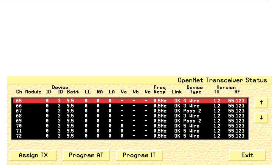
Displaying Transceiver Status
You can view transceiver status on the Central Station, but not on the PatientNet
Viewers (also known as the IRVS and RVS).
1. Press System on the Main screen.
2. Press OpenNet button on the Passcode screen to display the OpenNet Status
screen (fig. 90).
Fig. 90. OpenNet Status screen
Your System Administrator enables or disables the Assign TX, Program AT, and
Program IT buttons. Check with your System Administrator for more information.
The columns in the OpenNet Status screen are described below.
Ch channel number
Module ID Transceiver ID that the channel is currently set to
Device ID Device ID of the transceiver from which the channel receives data
Batt battery voltage of the ambulatory transceiver
LL left leg electrode impedance value
RA right arm electrode impedance value
LA left arm electrode impedance
Va chest electrode impedance value
Vb, Vc miscellaneous electrode impedance value
Freq Resp frequency response programmed into each transceiver
Link link between the transceiver and the Central Station:
OK: the Central Station is receiving data from the transceiver
OFF: the Central Station is not receiving data
Device
Type
transceiver or bedside monitor associated with the channel
Version TX the download firmware version currently in the transceiver
Version RX the RF Module firmware version currently in the transceiver
Ch channel number

WMTS TRANSCEIVERS
PatientNet Operator’s Manual, v1.04, 10001001-003, Revision B 185
All information contained herein is subject to the rights and restrictions on the title page.
Impedance Values
The DT-4500 Ambulatory Transceivers electrode impedance values, which are
displayed on the OpenNet Transceiver Status screen, indicate the quality of the signal
connection and are not the actual impedance values that are measured by the system.
The electrode impedance values range from 100 to 200 (optimal). The typical values
range between 180 and 200.
If the electrode’s impedance value is greater than the defined Quality Threshold value,
then its LED is illuminated. The DT-4500 stores the Quality Threshold value and uses
this value to determine whether or not the electrode LED should be illuminated when
the Attendant Present buttons are pressed. See Figure 91 on page 190 for details on the
DT-4500 Buttons and LED indicators.
Note: A Lead Off alarm will occur when an electrode’s impedance value drops to
150 (150 is the default Loose Lead Threshold value).
User Warnings, Cautions, and Notes
Before operating the WMTS transceivers, read and follow all warnings and cautions
presented in this section.
Warnings
1. Do not use the output of the DT-4500 as a synchronization source for car-
diac defibrillation. Delays in presentation of the R-Wave may be as much
as 40 milliseconds.
2. Do not monitor pacer patients with a 3 wire leadset when reliable pacer
detection is required. Pacer pulse detection can be erratic when only a
single vector is monitored. Always use a 5 wire leadset when reliable
pacer detection is required.
3. The DT-4500 is a type BF patient applied device. It is not suitable for
direct cardiac application, for use in the operating room, or during car-
diac surgery. Use in these environments could cause hazardous voltages
and currents being applied to the patient’s heart, resulting in cardiac
arrest.
4. Only authorized type BF devices can be plugged into the accessory con-
nector of the DT-4500 when it is applied to the patient. The accessory
connector must be kept covered when not in use with the supplied acces-
sory connector cover. Failure to follow these instructions could lead to
hazardous voltages and currents being applied to the patient resulting in
cardiac arrest.
5. Total submersion of the patient worn transceiver and/or patient leadset/
antenna may severely limit its transmission range causing loss of patient
monitoring. When subjecting the patient and transceiver to submersion,
he/she should be carefully monitored to ensure that there is no signal loss.
6. Use only VitalCom Power Supply Part Number 395005 with the DT-7000/
DT-7001.

WMTS TRANSCEIVERS
186 PatientNet Operator’s Manual, v1.04, 10001001-003, Revision B
All information contained herein is subject to the rights and restrictions on the title page.
7. The DT-7000/DT-7001 is not designed as a patient contact device. Per
FCC rules, the DT-7000/DT-7001 must reside more than 20 cm (7.9
inches) from the patient.
Cautions
1. Any changes or modifications to the device that are not expressly
approved by the party responsible for compliance could void the user’s
authority to operate this equipment.
2. Electromagnetic interference or power overload, due to electrosurgical or
diathermy instruments, may damage the device.
Notes
1. This equipment has been tested and found to comply with the limits for a
CLASS B digital device, pursuant to Part 15 of the FCC Rules and CISPR 11.
These limits are designed to provide reasonable protection against harmful
interference. This equipment generates, uses, and radiates radio frequency
energy, and, if not installed and used in accordance with the instructions con-
tained in this manual, may cause harmful interference to radio and television
communications. However, there is no guarantee that interference will not
occur in a particular installation.
If this equipment does cause harmful interference, then the user is encouraged
to try to correct the interference by one or more of the following measures:
• Move the DT-4500, the bedside device with a DT-7000 or DT-7001, or the
device being interfered with, to increase the separation between the two.
Note: Do not attempt to move fixed antennas as this can negatively impact the
PatientNet System’s operation.
• Connect the equipment into an outlet on a different circuit.
• Contact your technical service representative for assistance.
2. To ensure that the use of this product does not contribute to interference, it is
necessary to use shielded I/O cables. Connecting this device to peripheral
devices that do not comply with the CLASS B requirement or using an
unshielded peripheral data cable could result in harmful interference to radio
or television reception.
3. The DT-4500, DT-7000, and DT-7001 should be disposed of at the end of
their useful life per applicable regulations.

WMTS TRANSCEIVERS
PatientNet Operator’s Manual, v1.04, 10001001-003, Revision B 187
All information contained herein is subject to the rights and restrictions on the title page.
Ambulatory Transceiver (DT-4500)
The DT-4500 transceiver is a battery-operated ambulatory transceiver worn by the
patient and used with a 3, 4, or 5-wire leadset that is connected to electrodes on the
patient. The transceiver is available to patients who are not confined to a bed, but still
require constant monitoring of their ECG waveforms.
Operating Instructions
Push Button Function and Use
See Figure 91 on page 190 for an image of the DT-4500 controls and LED indicators.
External Serial Devices (I/O) Connector
The External Serial Device (I/O) connector allows an external serial device or pro-
gramming cable to connect and maintain a logical communication link between the
DT-4500 and the Central Station. See page 183 for details on programming the DT-
4500 through the I/O connector.
ECG Leadset Connector
The ECG leadset connector allows the ECG leadset to attach to the DT-4500 and
maintain a logical communication link between the DT-4500 and the Central Station.
See page 195 for details on attaching the ECG leadset to the DT-4500 through the
ECG leadset connector.
Remote Record
When depressed, the Remote Record function button will initiate a strip chart record-
ing at the Central Station.
Nurse Call
When depressed, the Nurse Call function button will initiate a Nurse Call Alarm at the
Central Station.

WMTS TRANSCEIVERS
188 PatientNet Operator’s Manual, v1.04, 10001001-003, Revision B
All information contained herein is subject to the rights and restrictions on the title page.
Attendant Present / Procedure Alarm Silence (PAS) Unlock Button
The Attendant Present/PAS Unlock Buttons consists of two buttons that are located
on either side of the transceiver (See Figure 91 on page 190). The Attendant Present
push buttons have three functions. Each function is initiated based on how long the
buttons are pressed.
1. Lead Quality
Pressing both Attendant Present buttons simultaneously will illuminate the LEDs for
each lead that has a minimum level of quality.
2. Initiating an Attendant Present Alarm
Once the transceiver is in the Power-On Mode, pressing the Attendant Present buttons
will activate the Attendant Present function and initiate an Attendant Present Alarm
at the Central Station.
3. Unlocking the PAS button
The PAS button must be unlocked or enabled prior to initiating the Procedure Alarm
Silence button. In the “locked” position, the PAS button is disabled.
To “unlock” the PAS button, press, and hold (for about two seconds), the Attendant
Present buttons until the Procedure Alarm Silence Status Indicator LED begins flash-
ing. Once the LED indicator starts flashing, the PAS button is in the “unlocked mode”
and functional.
Note: The PAS button must be pressed while the LED is still flashing. If it is
pressed after the LED has stopped flashing, then the PAS button will auto-
matically be “re-locked”.

WMTS TRANSCEIVERS
PatientNet Operator’s Manual, v1.04, 10001001-003, Revision B 189
All information contained herein is subject to the rights and restrictions on the title page.
Procedure Alarm Silence (PAS) Button
Depressing the PAS button, while the PAS Status Indicator LED is flashing, informs
the clinicians at the Central Station area that the attending nurse will be performing a
procedure to the patient that may cause inadvertent false alarms at the Central Station
(i.e. changing lead wires, electrodes, etc.)
Once the PAS button is pressed, the following events occur at the Central Station.
1. A timer is displayed in the fourth patient block configurable field that displays
the length of Procedure Alarm Silence time remaining on the transceiver.
CAUTION: All non-level one alarms are ignored while the PAS alarm is active.
2. “PA SILENCE” is denoted in Full Disclosure for the duration of the PAS
period.
Once the PAS button is pressed, the DT-4500 enters the PAS Mode with the following
indications:
1. The active time is set for 120 seconds and begins counting down.
2. The active time is transmitted to the Central Station.
3. The PAS Status LED indicates the time remaining through its flash speed. The
LED flash speed increases as the PAS time remaining decreases from 120 sec-
onds to 0 seconds.
4. The attendant can reset the PAS active time to 120 seconds by pressing both
Attendant Present buttons again.
The Procedure Alarm Silence alarm remains active until one of the following condi-
tions occur:
1. The transceiver no longer sends the procedure alarm silence indicator to the
Central Station.
2. A level one alarm is detected and triggered at the Central Station
3. The patient tile alarm text area is clicked on. All alarms are set to ON once
this area is clicked.
4. The attendant presses the PAS button while PAS is active. This will automati-
cally cancel the 120 second PAS at the Central Station, and will re-enable the
audible alarm tone.
Note: The PAS feature can be disabled by the System Administrator.
WMTS TRANSCEIVERS
190 PatientNet Operator’s Manual, v1.04, 10001001-003, Revision B
All information contained herein is subject to the rights and restrictions on the title page.
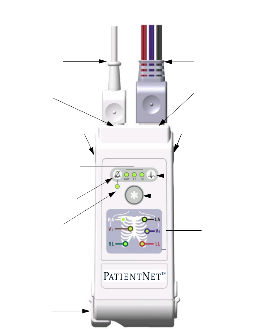
Fig. 91. DT-4500 Controls and LED Indicators
Note: *The External Serial Device (I/O) Cable must be removed and the Connector
must be covered whenever the DT-4500 is connected to the patient.
Battery Compartment
Electrode Status Indicators
Remote Record button
Battery Low, RF, and I/O
Connector Link Status Indicators
Procedure Alarm Silence button
Procedure Alarm Silence
Status Indicator
Nurse Call button
Attendant Present / Procedure
Alarm Silence Unlock buttons
ECG Leadset and connector
cover
*External Serial Device (I/O)
Cable
ECG Leadset Connector
*External Serial Device (I/O)
Connector

WMTS TRANSCEIVERS
PatientNet Operator’s Manual, v1.04, 10001001-003, Revision B 191
All information contained herein is subject to the rights and restrictions on the title page.
LED Indicators Function
Upon Power-On, all LED indicators are illuminated for a brief period. After the speci-
fied time period, only those LEDs displaying positive (or negative) transceiver func-
tions, as described in each section below, remain illuminated.
Procedure Alarm Silence Status Indicator
The Procedure Alarm Silence Status Indicator is illuminated when the PAS function is
active. The LED flashes while the Procedure Alarm Silence button is unlocked or the
PAS active time is running low. The PAS button can only be pressed and activated
during this unlocked phase. Refer to the section on “Procedure Alarm Silence (PAS)
Button” on page 189 for more information.
External Serial Devices (I/O)
The External Serial Device (I/O) LED is illuminated when an external serial device is
connected, detected and maintaining a logical communication link.
Note: When illuminated, be sure that the device is not connected to the patient.
Low Battery (BATT)
The Low Battery (BATT) LED is illuminated while the battery voltage remains good;
however, the LED flashes when the battery voltage falls below a predetermined value.
When the battery power falls below a predetermined value, then the transceiver will
automatically power itself off.
RF link (RF)
The RF link indicator is illuminated while there is RF communication between the
DT-4500 transceiver and the Central Station. The LED flashes if there is communica-
tion between the DT-4500 transceiver and the Access point, but not the Central Sta-
tion.
Electrode Status Indicators (RA, LA, RL, LL, V1)
Each ECG electrode wire is named, color coded (Table 21), and represented by an
LED indicator. Each LED is illuminated with a solid light when the electrode is fully
active, and is off when no electrode signal is present.
Table 21 Electrode Colors
Electrode Name Wire Color
RA White
LA Black
RL Green
LL Red
V1 Brown

WMTS TRANSCEIVERS
192 PatientNet Operator’s Manual, v1.04, 10001001-003, Revision B
All information contained herein is subject to the rights and restrictions on the title page.
The Quality Threshold value has a default setting. If the electrode’s impedance value
is greater than the default, then its LED is illuminated. The DT-4500 stores the Quality
Threshold value and uses this value to determine whether or not the electrode LED
should be illuminated when the Attendant Present buttons are pressed.
See “Impedance Values” on page 185 for details.
Note: The V6 indicator will be available in future releases; therefore, the V6 LED
will not illuminate when the Attendant Present buttons are pressed.

WMTS TRANSCEIVERS
PatientNet Operator’s Manual, v1.04, 10001001-003, Revision B 193
All information contained herein is subject to the rights and restrictions on the title page.
Cleaning
This section provides cleaning and maintenance instructions for DT-4500
transceivers.
Read and follow all precautions when cleaning transceivers.
WARNING: No claims are made concerning the sterility of the DT-4500 Ambulatory Trans-
ceivers.
CAUTION: Do not sterilize any part of the transceivers. Gas sterilization, autoclaving, liq-
uid immersion, and other sterilization methods can cause serious damage to
the devices that may not be obvious to the user.
Note: DO NOT use abrasive cleaners.
Cleaning the Chassis
The following applies to cleaning the DT-4500.
• The DT-4500 can be cleaned with the patient cable attached, however please
ensure that the cleaning agents used to clean the DT-4500 are compatible with
the cleaning agents listed for the ECG cable on page 194, or else ensure that
the ECG cable does not come into contact with the cleaning agents for the DT-
4500.
• To clean around the ECG connector, remove the ECG cable from the unit.
CAUTION: Prior to cleaning the battery compartment and transceiver chassis, remove
the battery from the unit.
1. Remove the battery from the transceiver and inspect the battery compartment
after each use. Close the battery door.
CAUTION: Prior to rinsing the DT-4500, make sure that the battery compartment door is
properly closed and sealed.
2. Transceivers can be cleaned with a gauze pad or cloth moistened with one of
the following agents:.
• Soap and Water
• Quaternary Ammonium
• Glutaraldehyde 2%
• Dilute Chlorine Bleach (Sodium hypochlorite), 10% solution, freshly
made in past 24 hours
• Isopropyl Alcohol 70%
• Ethyl Alcohol
3. Use a cloth moistened with distilled water to rinse away the cleaning solution.
4. Dry thoroughly with a lint-free cloth.

WMTS TRANSCEIVERS
194 PatientNet Operator’s Manual, v1.04, 10001001-003, Revision B
All information contained herein is subject to the rights and restrictions on the title page.
Note: Once a month, or whenever the DT-4500 is submersed or subjected to a
stream of liquid, remove the accessory connector cover and remove any
moisture that may have collected inside.
Cleaning the Battery Compartment
CAUTION: When cleaning the battery compartment, use only soap, water, or alcohol. Do
not use any other cleaning agents inside the battery compartment as they
may damage the battery compartment.
CAUTION: Make sure to rinse all cleaned surfaces with distilled water to remove any
cleaning agent residue. Dry off the battery contact leads. Ensure that the bat-
tery compartment is dry before inserting the battery into the unit.
Under normal operation, the battery compartment should not require frequent clean-
ing. If the battery compartment does require cleaning, then use the following instruc-
tions.
1. Remove the battery from the battery compartment.
2. Clean the transceiver with a gauze pad or cloth moistened with one of the fol-
lowing agents:
• Water
•Soap
3. Use a cloth moistened with distilled water to rinse away the cleaning solution.
4. Dry thoroughly with a lint-free cloth. Allow the battery compartment to air
dry completely prior to closing the compartment door.
Cleaning the ECG Leadsets
The transceiver ECG Leadsets are manufactured by Affinity Medical.
Contact your technical support representative for additional leadsets.
Warnings
1. Do not use leadsets which exhibit signs of wear or damage such as crack-
ing or degradation of the connectors or cable insulation.
2. Do not sterilize using steam or gamma radiation. Damage to the leadsets
will result.
Cautions
1. To increase the life of the leadsets, do not pull on the leadsets to discon-
nect. Pull gently by grasping the connectors.
2. Do not immerse the leadsets in water or other liquid to clean. Immersion
may cause damage to the leadsets.
3. Repeated exposure to EtO sterilization will shorten the effective life of the
leadset. The leadsets should be sterilized only when indicated by specific
patient or hospital requirements.

WMTS TRANSCEIVERS
PatientNet Operator’s Manual, v1.04, 10001001-003, Revision B 195
All information contained herein is subject to the rights and restrictions on the title page.
Cleaning
1. Wipe the leadset with a solution of soap and water.
2. Use a cloth moistened with distilled water to rinse away the cleaning solution.
3. Dry thoroughly with a lint-free cloth.
Disinfecting
Use hospital-approved disinfecting procedures such as those recommended by AAMI
or AORN.
1. Wipe the leadset with a fresh 10% solution of chlorine bleach and water or a
2% gluteraldehyde solution such as Cidex.
2. Use a cloth moistened with distilled water to rinse away the cleaning solution.
3. Dry thoroughly with a lint-free cloth.
Sterilization
Leadsets may be sterilized by EtO, when indicated. Use the hospital-approved proce-
dure for EtO sterilization, such as those recommended by AAMI. The Leadsets are
designed to remain effective after up to 10 exposures to EtO sterilization Cycles.
Use and Maintenance
Transceiver Storage
Store the transceiver with the leadset attached and hanging freely. If that is not possi-
ble, then wrap the leadset loosely around the transceiver. Wrapping the leadset tightly
around the transceiver can damage the wires.
Note: The DT-4500 Ambulatory Transceiver contains no user-serviceable parts.
Thus, maintenance service is not needed.
Attaching and Removing a Leadset from the Transceiver
To attach, carefully grasp the leadset connector cover, holding it with the small knob
facing upward, and push the leadset into the ECG lead wire connector. Make sure that
the leadset is completely inserted into the connector and is flush with the DT-4500
chassis.
To remove the leadset, grasp hold of the sides of the leadset connector cover and pull
straight out. If the leadset is difficult to remove, then you can slightly move the leadset
cover side-to-side until it is released.
Internal Antenna
The DT-4500 transmits in the 608-614 MHz frequency range. The omnidirectional
antenna is a part of the leadset system, with each lead wire paired with an antenna
wire. Transceiver output power and system operation requirements are defined by the
FCC. Therefore, it is essential that the leadset provided not be modified or altered
in any way.

WMTS TRANSCEIVERS
196 PatientNet Operator’s Manual, v1.04, 10001001-003, Revision B
All information contained herein is subject to the rights and restrictions on the title page.
Installing and Removing a Battery
See “Specifications” on page 247 for acceptable batteries.
Note: Battery service life can be substantially improved by using nine-volt lithium
batteries.
To install a 9V transceiver battery, first open the transceiver battery compartment by
placing your thumb and forefinger on the compartment latch and flipping it open.
Inspect the battery compartment and insure that there is no foreign object present that
could block the battery contact or short the battery terminals. Next, place a 9V battery
inside the compartment with the prongs touching the compartment contacts. The ori-
entation of the battery prongs against the contacts does not matter, so long as the
prongs and contacts are touching. Finally, close the battery compartment door by
pressing it until the latch clicks into place and the compartment is secure.
To remove a battery, simply follow the installation steps listed above and discard the
used battery per applicable regulations.
Warnings
1. ECG lead wires must be dressed and secured to the patient to prevent the
possibility of them encircling the patient’s neck and causing strangula-
tion.
2. When installing or replacing the battery, visually inspect the battery
compartment and ensure that there are no foreign objects inside. A con-
ductive object making contact with the battery contacts could cause the
battery and battery compartment to overheat, resulting in burns to the
patient and to the attendant removing the battery.
3. A foreign object blocking battery contact with the DT-4500 could prevent
its operation resulting in failure to monitor the patient.
4. Always perform a battery check procedure after installing or replacing
the battery.
5. Lithium Batteries may explode if mistreated. DO NOT recharge, disas-
semble, or dispose of batteries in fire.
Cautions
1. Transceivers should be carried securely in pouches or in a pocket of a
patient’s gown. If the weight of the transceiver pulls on the wires, then
the wires can be damaged or worn
2. Make sure that the wires are not twisted around each other; since, this
can interfere with transmission and produce noise.
3. Make sure that the lead wires are not inadvertently pinched in the bed
rails. This may cut the insulation or break the leadset.

WMTS TRANSCEIVERS
PatientNet Operator’s Manual, v1.04, 10001001-003, Revision B 197
All information contained herein is subject to the rights and restrictions on the title page.
Instrument Transceiver (DT-7000, DT-7001)
WARNING: When using a bedside device with the instrument transceiver (DT-7000/7001),
the bedside device is the primary monitor and alarm source. Disabling
alarms on the bedside device is not safe clinical practice.
The DT-7000 and DT-70011 send data and alarm information from bedside monitors
and NPB 7200 series ventilators to the Central Station.
The transceivers support the bedside monitors shown in the PatientNet Customer
Release Notes. See you system administrator for details.
Power to the DT-7000 is provided through one of the following:
• the AC power adapter, which provides continuous power
• the bedside monitor, which provides continuous power
Power to the DT-7001 is provided through one of the following:
• the AC power adapter, which provides continuous power
• the bedside monitor, which provides continuous power
• the internal battery, which is replaceable by qualified service
technicians
Note: See your hospital’s Service Department for battery replacement.
Operating Instructions
The DT-7000 and DT-7001 appearance and functionality are equivalent; however,
only the DT-7001 is capable of using an internal battery as a power source.
Push Button Function and Use
See Figure 92 on page 200 for an image of the DT-7000/DT-7001 controls and LED
indicators.
External Serial Devices (I/O) Ports
The External Serial Device (I/O) ports allow external serial devices or programming
cables to connect and maintain logical communication links between the DT-7000/
DT-7001 and the Central Station.
Note: *External Serial Device (I/O) Port 1 is currently functional. I/O Ports 2, 3 and
4 will be functional in future product releases.
1. The DT-7001 will be available in future releases. Please contact your sales representative for the
device availability.

WMTS TRANSCEIVERS
198 PatientNet Operator’s Manual, v1.04, 10001001-003, Revision B
All information contained herein is subject to the rights and restrictions on the title page.
Remote Record
When depressed, the Remote Record function button will initiate a strip chart
recording at the Central Station.
Nurse Call
When depressed, the Nurse Call function button will initiate a Nurse Call Alarm at the
Central Station.
Power Button
Pressing the Power button either places the transceiver in or out of Standby Mode.
Attendant Present / Procedure Alarm Silence (PAS) Unlock Button
The Attendant Present push button has two functions. Each function is initiated based
on how long the button is pressed.
Note: The LEDs are constantly illuminated when powered by an external source.
1. Initiating an Attendant Present Alarm
Once the transceiver is out of the Standby Mode, pressing the Attendant Present but-
ton will activate the Attendant Present function and initiate an Attendant Present
Alarm at the Central Station.
2. Unlocking the PAS button
The PAS function must be enabled at the Central Station prior to initiating the Proce-
dure Alarm Silence alarm at the DT-7000/DT-7001.
In the “locked” position, the PAS button is disabled.
To “unlock” the PAS button, press, and hold (for about two seconds), the Attendant
Present button until the Procedure Alarm Silence Status Indicator LED begins flash-
ing. Once the LED indicator starts flashing, the PAS button is in the “unlocked mode”
and functional.
Note: The PAS button must be pressed while the LED is still flashing. If it is
pressed after the LED has stopped flashing, then the PAS button will auto-
matically be “re-locked”.

WMTS TRANSCEIVERS
PatientNet Operator’s Manual, v1.04, 10001001-003, Revision B 199
All information contained herein is subject to the rights and restrictions on the title page.
Procedure Alarm Silence (PAS) Button
Depressing the PAS button, while the PAS Status Indicator LED is flashing, informs
the clinicians at the Central Station area that the attending nurse will be performing a
procedure to the patient that may cause inadvertent false alarms at the Central Station
(i.e. changing lead wires, electrodes, etc.)
Once the PAS button is pressed, the following events occur at the Central Station.
1. A timer is displayed in the fourth patient block configurable field that displays
the length of Procedural Alarm Silence time remaining on the transceiver.
CAUTION: All non-level one alarms are ignored while the PAS alarm is active.
2. “PA SILENCE” is denoted in Full Disclosure for the duration of the PAS
period.
Once the PAS button is pressed, the DT-7000/7001 enters the PAS Mode with the fol-
lowing indications:
1. The active time is set for 120 seconds and begins counting down.
2. The active time is transmitted to the Central Station.
3. The PAS Status LED indicates the time remaining through its flash speed. The
LED flash speed increases as the PAS time remaining decreases from 120 sec-
onds to 0 seconds.
4. The attendant can reset the PAS active time to 120 seconds by pressing both
Attendant Present buttons again.
The Procedure Alarm Silence remains active until one of the following conditions
occur:
1. The transceiver no longer sends the procedure alarm silence indicator to the
Central Station.
2. A level one alarm is detected and triggered at the Central Station
3. The patient tile alarm text area is clicked on. All alarms are set to ON once
this area is clicked.
4. The attendant presses the PAS button while PAS is active. This will automati-
cally cancel the 120 second PAS at the Central Station, and will re-enable the
audible alarm tone.
WMTS TRANSCEIVERS
200 PatientNet Operator’s Manual, v1.04, 10001001-003, Revision B
All information contained herein is subject to the rights and restrictions on the title page.
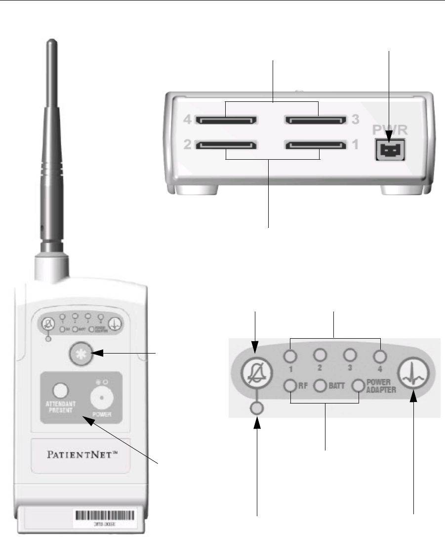
Fig. 92. DT-7000/DT-7001 Controls, I/O Ports, and LED Indicators
Note: *Only Port 1 of the External Serial Device (I/O) is functional. I/O Ports 2, 3
and 4 will be functional in future product releases.
External Serial Devices
(I/O) Ports 3 and 4*
Nurse Call
button
Attendant
Present and
Power buttons
Procedure Alarm
Silence (PAS) button
PAS Status Indicator Remote Record button
External Serial Devices
(I/O) Ports Status Indicators*
RF, Low Battery,
and Power Adapter
Indicators
Power Connector
Front View
External Serial Devices
(I/O) Ports 1 and 2*
Bottom View

WMTS TRANSCEIVERS
PatientNet Operator’s Manual, v1.04, 10001001-003, Revision B 201
All information contained herein is subject to the rights and restrictions on the title page.
LED Indicators Function
Once the transceivers exit Standby Mode, either by pressing the Attendant Present or
Power buttons, all LED indicators are illuminated for a brief period. After the speci-
fied time period, only those LEDs displaying positive (or negative) transceiver func-
tions, as described in each section below, remain illuminated.
Procedure Alarm Silence Status Indicator
The Procedure Alarm Silence Status Indicator is illuminated when the PAS function is
active. The LED flashes while the Procedure Alarm Silence button is unlocked or the
PAS active time is running low. The PAS button can only be pressed and activated
during this unlocked phase. Refer to the section on “Procedure Alarm Silence (PAS)
Button” on page 189 for more information.
External Serial Devices (I/O)
The External Serial Device (I/O) LEDs are labeled 1-4 and are each illuminated when
there is an external serial device connected, detected, and maintaining a logical com-
munication link to the corresponding I/O data port (fig. 92).
Low Battery (BATT)
Note: The Low Battery LED is only functional on the DT-7001.
The Low Battery (BATT) LED is illuminated while the battery voltage remains good;
however, the LED flashes when the battery voltage falls below a predetermined value.
When the battery power falls below a predetermined value, then the transceiver will
automatically power itself off.
RF Link (RF)
The RF link indicator is illuminated while there is RF communication between the
DT-7000 and DT-7001 transceivers and the Central Station. The LED flashes if there
is communication between the transceivers and the Access point, but not the Central
Station.
Power Adapter
The Power Adapter LED is illuminated when the transceiver is powered from an
external power source that is connected to the Power Connector (fig. 92), and not one
of the I/O ports.

WMTS TRANSCEIVERS
202 PatientNet Operator’s Manual, v1.04, 10001001-003, Revision B
All information contained herein is subject to the rights and restrictions on the title page.
Cleaning
This section provides cleaning and maintenance instructions for DT-7000 and DT-
7001 transceivers.
Read and follow all precautions when cleaning transceivers.
WARNING: No claims are made concerning the sterility of the DT-7000 and DT-7001
Instrument Transceivers.
CAUTION: Do not sterilize any part of the transceivers. Gas sterilization, autoclaving, liq-
uid immersion, and other sterilization methods can cause serious damage to
the devices that may not be obvious to the user.
Note: DO NOT use abrasive cleaners.
Cleaning the Chassis
1. Transceivers can be cleaned with a gauze pad or cloth moistened with one of
the following agents:.
• Soap and Water
• Quaternary Ammonium
• Glutaraldehyde 2%
• Dilute Chlorine Bleach (sodium hypochlorite), 10% solution, freshly made
in past 24 hours
• Isopropyl Alcohol 70%
• Ethyl Alcohol
2. Use a cloth moistened with distilled water to rinse away the cleaning solution.
3. Dry thoroughly with a lint-free cloth.

WMTS TRANSCEIVERS
PatientNet Operator’s Manual, v1.04, 10001001-003, Revision B 203
All information contained herein is subject to the rights and restrictions on the title page.
Use and Maintenance
Connecting to the Bedside Monitor
See Figure 92 on page 200 for an image of the DT-7000/DT-7001 controls and LED
indicators.
Note: Before the transceiver is connected to the bedside monitor, the system
administrator must program it with the bedside device specific software
module.
1. Attach the transceiver to the bedside monitor by sliding the Device Hook over
the Mounting Disk until the transceiver snaps into place. The Mounting Disk
is provided with the transceiver and is attached to the bedside device through
adhesive or hardware tools.
2. Connect the AC power adapter into the power port located on the bottom of
the transceiver.
3. Plug the AC power adapter into the wall electrical outlet. If the AC power
adapter is not used, the transceiver will operate either from its internal battery
(DT-7001 models) or, on some bedsides, from connection to the bedside
device.
4. Attach the host end of the I/O cable to I/O port 1 (Ports 2, 3 and 4 will be
functional in future releases).
5. Attach the other end of the I/O cable to the bedside monitor.

WMTS TRANSCEIVERS
204 PatientNet Operator’s Manual, v1.04, 10001001-003, Revision B
All information contained herein is subject to the rights and restrictions on the title page.
This page is intentionally left blank.