GE Medical Systems Information Technologies 2014748-002 Medical Telemetry Transmitter User Manual
GE Medical Systems Information Technologies Inc. Medical Telemetry Transmitter
UserManual.wiki
>
GE Medical Systems Information Technologies
>
2014748-002 User Manual
>
Manual Draft1 Part 5
Contents
1.
Manual Draft2 Excerpt
2.
Manual Draft1 Part 1
3.
Manual Draft1 Part 2
4.
Manual Draft1 Part 3
5.
Manual Draft1 Part 4
6.
Manual Draft1 Part 5
7.
Manual Draft1 Part 6
8.
Manual Draft1 Part 7
Manual Draft1 Part 5
Navigation menu
Upload a User Manual
Namespaces
Wiki Guide
HTML
PDF
Info
Views
User Manual
Discussion / Help
Navigation
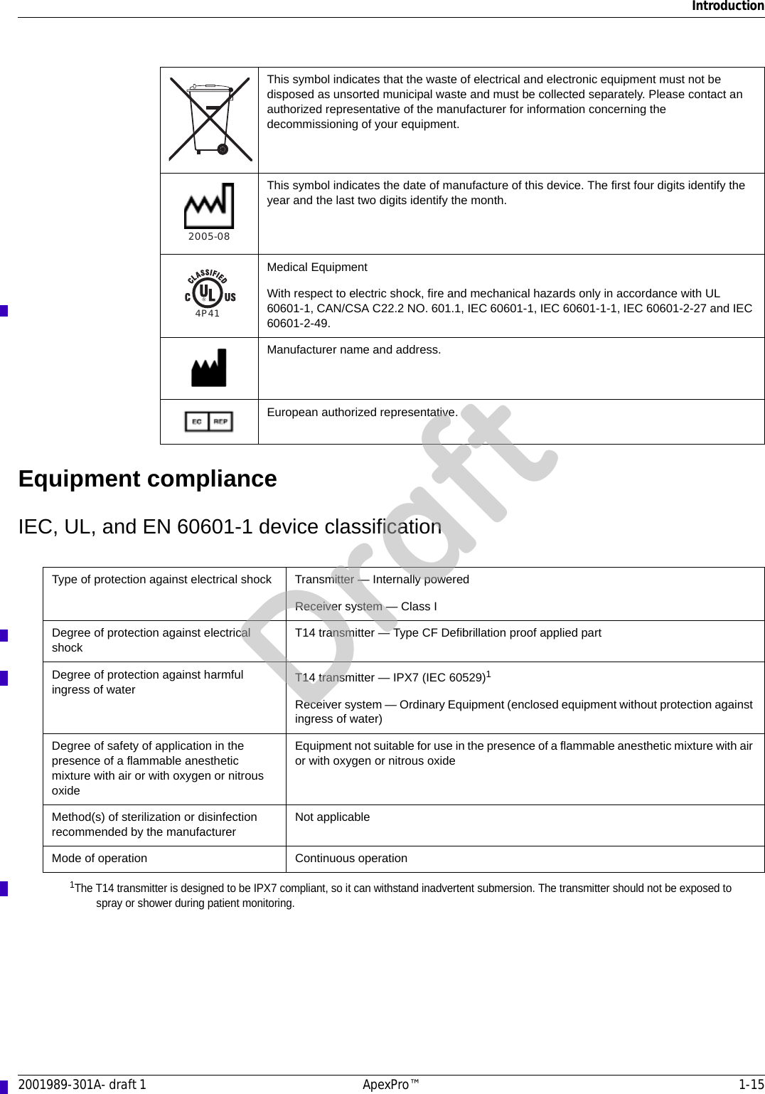
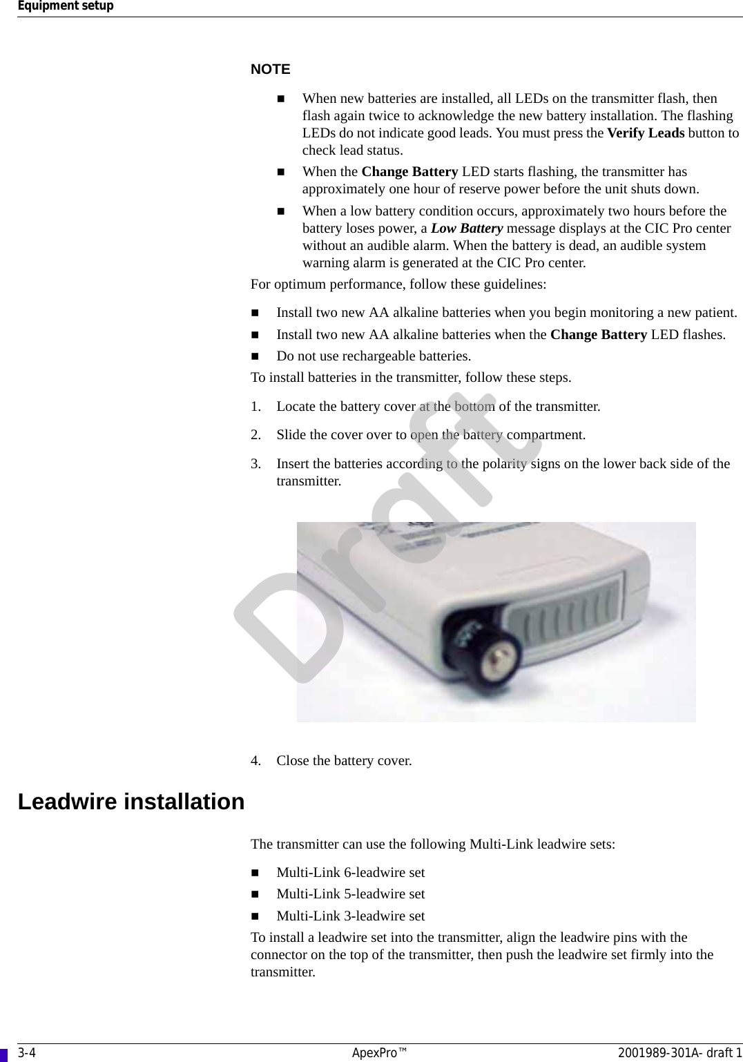
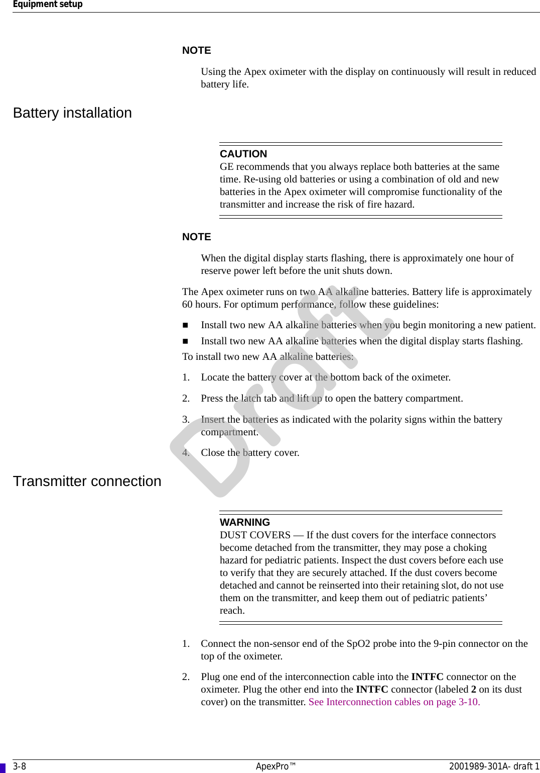
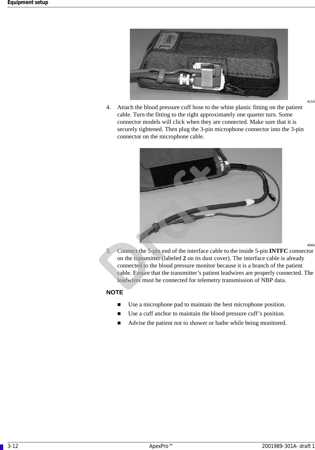
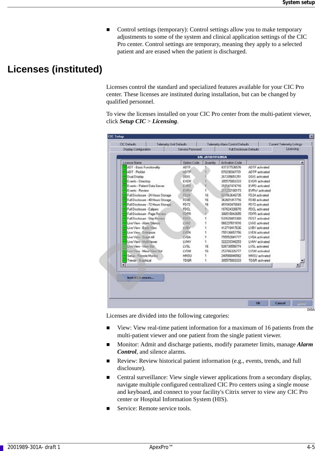
![1-14 ApexPro™ 2001989-301A- draft 1IntroductionNotesNote statements provide application tips or other useful information.The following note statements apply to this system. Put the CIC Pro center in a location where you can easily see the screen and access the operating controls.This product is not likely to cause abnormal operation of other patient-connected equipment such as cardiac pacemakers or other electrical stimulators. Exceptions are noted in the pacemaker monitoring section, if applicable.This product is protected against the effects of cardiac defibrillator discharges to ensure proper recovery, as required by test standards.This equipment is suitable for use in the presence of electrosurgery.Equipment symbolsNOTESome symbols may not appear on all equipment.ATTENTION: Consult accompanying documents.TYPE B APPLIED PART: Non-isolated applied part suitable for intentional external and internal application to the patient excluding direct cardiac application.[Medical Standard Definition:] Applied part complying with the specified requirements of IEC/EN/UL 60601-1 Medical Standards to provide protection against electric shock, particularly regarding allowable leakage current.TYPE CF APPLIED PART: Isolated (floating) applied part suitable for intentional external and internal application to the patient including direct cardiac application. “Paddles” outside the box indicate the applied part is defibrillator proof.[Medical Standard Definition:] F-type applied part (floating/isolated) complying with the specified requirements of IEC/EN/UL 60601-1 Medical Standards to provide a higher degree of protection against electric shock than that provided by Type BF applied parts.Interface connector(s)Complies with IPX3 standards (IEC 60529) for protection against water ingress under test conditions; water sprayed at an angle up to 60 degrees on either side of the vertical axis shall have no harmful effects, with device not in actual use. Complies with IPX7 standards (IEC 60529) for protection against water ingress under test conditions; immersion in one meter of water for 30 minutes, with device not in actual use. Operation of this equipment requires the prior coordination with a frequency coordinator designated by the FCC for the Wireless Medical Telemetry Service.Non-ionizing electromagnetic radiation: To indicate elevated, potentially dangerous, levels of non-ionizing radiation. Note - In case of application in a warning sign the rules according to ISO 3864-1 shall be adhered to.IEC 60878 note: See safety sign ISO 7010 - W005 "Warning, non-ionizing radiation".INTFC.Draft](https://usermanual.wiki/GE-Medical-Systems-Information-Technologies/2014748-002.Manual-Draft1-Part-5/User-Guide-881641-Page-2.png)