GE Medical Systems Information Technologies 2014748 Medical Telemetry Transmitter worn on body User Manual 2001989 135A
GE Medical Systems Information Technologies Inc. Medical Telemetry Transmitter worn on body 2001989 135A
Contents
- 1. Users Manual 1 of 3
- 2. Users Manual 2 of 3
- 3. Users Manual 3 of 3 Safety
- 4. 2001989 135A APEX Manual DRAFT
2001989 135A APEX Manual DRAFT

GE Medical Systems
Information Technologie
s
g
gemedical.com
APEX, ApexPro and ApexPro CH
Transmitter Programming Instructions
Software Version 2
2001989-135 Revision A - Draft 7
Draft

T-2 APEX‚ and ApexPro‘ Transmitter Programming InstructionsRevision A - Draft 7
2001989-1358/5/03
NOTE:
NOTE: NOTE:
NOTE:
The information in this manual only applies to APEX, ApexPro, and ApexPro CH Transmitter Programming
Instructions software version 1. It does not apply to earlier software versions. Due to continuing product
innovation, specifications in this manual are subject to change without notice.
Listed below are GE Medical Systems Information Technologies trademarks used in this manual. All other
trademarks contained herein are the property of their respective owners.
UNITY NETWORK, ApexPro, CD TELEMETRY, TRAMSCOPE, EAGLE, SOLAR, DASH, MARS, and RSVP are
trademarks of GE Medical Systems Information Technologies registered in the United States Patent and
Trademark Office.
CD TELEMETRY®–LAN, CENTRALSCOPE, ICMMS, Octacomm, and Octanet are trademarks of GE
Medical Systems Information Technologies.
© GE Medical Systems Information Technologies, 2000-2003. All rights reserved.
Draft

Revision A- Draft 6 APEX and ApexPro Transmitter Programming Instructions iii
2001989-135
Contents
1Introduction . . . . . . . . . . . . . . . . . . . . . . . . . . . . . . . . . . . . . . 7
Overview . . . . . . . . . . . . . . . . . . . . . . . . . . . . . . . . . . . . . . . . . . . . . . . . . . . . . . . . . . . . . 8
Standards Used in this Manual . . . . . . . . . . . . . . . . . . . . . . . . . . . . . . . . . . . . . . . . 8
Definitions . . . . . . . . . . . . . . . . . . . . . . . . . . . . . . . . . . . . . . . . . . . . . . . . . . . . 8
Illustrations and Names . . . . . . . . . . . . . . . . . . . . . . . . . . . . . . . . . . . . . . . . . . 8
Document Revision History . . . . . . . . . . . . . . . . . . . . . . . . . . . . . . . . . . . . . . . . . . . 8
Install the Programming Device . . . . . . . . . . . . . . . . . . . . . . . . . . . . . . . . . . . . . . . . . . 9
Hardware Requirements for the Programming Device . . . . . . . . . . . . . . . . . . . . . . 9
Install the Software . . . . . . . . . . . . . . . . . . . . . . . . . . . . . . . . . . . . . . . . . . . . . . . . 10
Remove the Previous Version of Software . . . . . . . . . . . . . . . . . . . . . . . . . . 10
Run the Installation Wizard . . . . . . . . . . . . . . . . . . . . . . . . . . . . . . . . . . . . . . 11
Connect the Hardware . . . . . . . . . . . . . . . . . . . . . . . . . . . . . . . . . . . . . . . . . . . . . . 11
Disconnect the Hardware . . . . . . . . . . . . . . . . . . . . . . . . . . . . . . . . . . . . . . . . . . . . 12
Run the Apex & ApexPro Programming Box Software . . . . . . . . . . . . . . . . . . . . . . 13
Start the Software . . . . . . . . . . . . . . . . . . . . . . . . . . . . . . . . . . . . . . . . . . . . . . . . . 13
Select the Transmitter . . . . . . . . . . . . . . . . . . . . . . . . . . . . . . . . . . . . . . . . . . . . . . 13
Select a Hospital . . . . . . . . . . . . . . . . . . . . . . . . . . . . . . . . . . . . . . . . . . . . . . . . . . 14
Generate Reports . . . . . . . . . . . . . . . . . . . . . . . . . . . . . . . . . . . . . . . . . . . . . . . . . 15
Excel Report . . . . . . . . . . . . . . . . . . . . . . . . . . . . . . . . . . . . . . . . . . . . . . . . . 15
Log Report . . . . . . . . . . . . . . . . . . . . . . . . . . . . . . . . . . . . . . . . . . . . . . . . . . . 17
Apex and ApexPro Transmitter Programming Instructions Manual . . . . . . . . 18
Flyover Windows . . . . . . . . . . . . . . . . . . . . . . . . . . . . . . . . . . . . . . . . . . . . . . 18
About the Apex Program . . . . . . . . . . . . . . . . . . . . . . . . . . . . . . . . . . . . . . . . 18
Program Other Transmitters . . . . . . . . . . . . . . . . . . . . . . . . . . . . . . . . . . . . . . . . . . . . 19
2Apex Transmitter . . . . . . . . . . . . . . . . . . . . . . . . . . . . . . . . . 21
Program the Transmitter’s Basic Functions . . . . . . . . . . . . . . . . . . . . . . . . . . . . . . . 23
The Main Programming Window . . . . . . . . . . . . . . . . . . . . . . . . . . . . . . . . . . . . . . 23
Message Area . . . . . . . . . . . . . . . . . . . . . . . . . . . . . . . . . . . . . . . . . . . . . . . . . . . . 23
TTX Number and Frequency Settings . . . . . . . . . . . . . . . . . . . . . . . . . . . . . . . . . . 23
Band Setting . . . . . . . . . . . . . . . . . . . . . . . . . . . . . . . . . . . . . . . . . . . . . . . . . . . . . 24
Reference Lead Setting . . . . . . . . . . . . . . . . . . . . . . . . . . . . . . . . . . . . . . . . . . . . . 25
For 5- or 6-Lead Cables . . . . . . . . . . . . . . . . . . . . . . . . . . . . . . . . . . . . . . . . . 25
For 3-Lead Cables . . . . . . . . . . . . . . . . . . . . . . . . . . . . . . . . . . . . . . . . . . . . . 25
Alarm Pause Setting . . . . . . . . . . . . . . . . . . . . . . . . . . . . . . . . . . . . . . . . . . . . . . . 26
Firmware Code Revision Number . . . . . . . . . . . . . . . . . . . . . . . . . . . . . . . . . . . . . 26
Exit Button . . . . . . . . . . . . . . . . . . . . . . . . . . . . . . . . . . . . . . . . . . . . . . . . . . . . . . . 26
Draft

iv APEX and ApexPro Transmitter Programming Instructions Revision A- Draft 6
2001989-135
Perform Advanced Functions . . . . . . . . . . . . . . . . . . . . . . . . . . . . . . . . . . . . . . . . . . . 27
Perform Advanced Programming . . . . . . . . . . . . . . . . . . . . . . . . . . . . . . . . . . . . . . 27
Communication Status Button . . . . . . . . . . . . . . . . . . . . . . . . . . . . . . . . . . . . 27
Set Serial Number . . . . . . . . . . . . . . . . . . . . . . . . . . . . . . . . . . . . . . . . . . . . . 27
Change Alarm Pause Setting . . . . . . . . . . . . . . . . . . . . . . . . . . . . . . . . . . . . . 27
Monitor the Status of Transmitter Tests . . . . . . . . . . . . . . . . . . . . . . . . . . . . . 28
Apex Appendices . . . . . . . . . . . . . . . . . . . . . . . . . . . . . . . . . . . . . . . . . . . . . . . . . . . . . 29
Appendix 1: Apex Troubleshooting . . . . . . . . . . . . . . . . . . . . . . . . . . . . . . . . . . . . 29
LED Status Problems . . . . . . . . . . . . . . . . . . . . . . . . . . . . . . . . . . . . . . . . . . . 29
Programming Problems . . . . . . . . . . . . . . . . . . . . . . . . . . . . . . . . . . . . . . . . . 29
Test Status Failures . . . . . . . . . . . . . . . . . . . . . . . . . . . . . . . . . . . . . . . . . . . . 30
Technical Support . . . . . . . . . . . . . . . . . . . . . . . . . . . . . . . . . . . . . . . . . . . . . 30
Appendix 2: Access Apex Technical Functions . . . . . . . . . . . . . . . . . . . . . . . . . . . 31
Requirements . . . . . . . . . . . . . . . . . . . . . . . . . . . . . . . . . . . . . . . . . . . . . . . . . 31
Access the Super User Mode . . . . . . . . . . . . . . . . . . . . . . . . . . . . . . . . . . . . 31
Appendix 3: Apex TTX Labels . . . . . . . . . . . . . . . . . . . . . . . . . . . . . . . . . . . . . . . . 32
3ApexPro CH Transmitter . . . . . . . . . . . . . . . . . . . . . . . . . . 33
Program the Transmitter’s Basic Functions . . . . . . . . . . . . . . . . . . . . . . . . . . . . . . . 35
The Main Programming Window . . . . . . . . . . . . . . . . . . . . . . . . . . . . . . . . . . . . . . 35
TTX Number and Frequency Settings . . . . . . . . . . . . . . . . . . . . . . . . . . . . . . . . . . 36
For 5- or 6-Lead Cables . . . . . . . . . . . . . . . . . . . . . . . . . . . . . . . . . . . . . . . . . 37
For 3-Lead Cables . . . . . . . . . . . . . . . . . . . . . . . . . . . . . . . . . . . . . . . . . . . . . 37
Alarm Pause Setting . . . . . . . . . . . . . . . . . . . . . . . . . . . . . . . . . . . . . . . . . . . . . . . 37
Filter Setting . . . . . . . . . . . . . . . . . . . . . . . . . . . . . . . . . . . . . . . . . . . . . . . . . . . . . . 38
Exit Button . . . . . . . . . . . . . . . . . . . . . . . . . . . . . . . . . . . . . . . . . . . . . . . . . . . . . . . 38
Help . . . . . . . . . . . . . . . . . . . . . . . . . . . . . . . . . . . . . . . . . . . . . . . . . . . . . . . . . . . . 38
View Transmitter Diagnostics . . . . . . . . . . . . . . . . . . . . . . . . . . . . . . . . . . . . . . . . . . 39
View Test Results . . . . . . . . . . . . . . . . . . . . . . . . . . . . . . . . . . . . . . . . . . . . . . . . . 39
Power-up Self Test Status . . . . . . . . . . . . . . . . . . . . . . . . . . . . . . . . . . . . . . . 39
Diagnostic Test . . . . . . . . . . . . . . . . . . . . . . . . . . . . . . . . . . . . . . . . . . . . . . . 40
Serial Number . . . . . . . . . . . . . . . . . . . . . . . . . . . . . . . . . . . . . . . . . . . . . . . . 41
Code Version Numbers . . . . . . . . . . . . . . . . . . . . . . . . . . . . . . . . . . . . . . . . . 41
Communication Status Button . . . . . . . . . . . . . . . . . . . . . . . . . . . . . . . . . . . . 41
Update Transmitter Firmware . . . . . . . . . . . . . . . . . . . . . . . . . . . . . . . . . . . . . . . . . . . 42
Update Firmware Code . . . . . . . . . . . . . . . . . . . . . . . . . . . . . . . . . . . . . . . . . . . . . 42
Firmware Download . . . . . . . . . . . . . . . . . . . . . . . . . . . . . . . . . . . . . . . . . . . . 42
Erase & Download Application Code . . . . . . . . . . . . . . . . . . . . . . . . . . . . . . . 42
Erase & Download Service Code . . . . . . . . . . . . . . . . . . . . . . . . . . . . . . . . . . 45
Verify the Transmitter’s Firmware Code Version . . . . . . . . . . . . . . . . . . . . . . 48
Verify Transmitter Operation . . . . . . . . . . . . . . . . . . . . . . . . . . . . . . . . . . . . . 48
Track the Software Upgrade (Field Engineer Use Only) . . . . . . . . . . . . . . . . . . . . 48
ApexPro CH Appendices . . . . . . . . . . . . . . . . . . . . . . . . . . . . . . . . . . . . . . . . . . . . . . 49
Draft

Revision A- Draft 6 APEX and ApexPro Transmitter Programming Instructions v
2001989-135
Appendix 1: ApexPro CH Troubleshooting . . . . . . . . . . . . . . . . . . . . . . . . . . . . . . 49
LED Status Problems . . . . . . . . . . . . . . . . . . . . . . . . . . . . . . . . . . . . . . . . . . . 49
Programming Problems . . . . . . . . . . . . . . . . . . . . . . . . . . . . . . . . . . . . . . . . . 50
Power-Up Self-Test Failures . . . . . . . . . . . . . . . . . . . . . . . . . . . . . . . . . . . . . 50
Other Problems . . . . . . . . . . . . . . . . . . . . . . . . . . . . . . . . . . . . . . . . . . . . . . . 51
Reset the Transmitter Manually . . . . . . . . . . . . . . . . . . . . . . . . . . . . . . . . . . . 51
Technical Support . . . . . . . . . . . . . . . . . . . . . . . . . . . . . . . . . . . . . . . . . . . . . 51
Appendix 2: Access ApexPro CH Technical Functions (Super User) . . . . . . . . . . 52
Requirements . . . . . . . . . . . . . . . . . . . . . . . . . . . . . . . . . . . . . . . . . . . . . . . . . 52
Access Super User Mode . . . . . . . . . . . . . . . . . . . . . . . . . . . . . . . . . . . . . . . 52
Test Pattern . . . . . . . . . . . . . . . . . . . . . . . . . . . . . . . . . . . . . . . . . . . . . . . . . . . . . . 54
Modulation . . . . . . . . . . . . . . . . . . . . . . . . . . . . . . . . . . . . . . . . . . . . . . . . . . . . . . . 54
Download EEPROM Code . . . . . . . . . . . . . . . . . . . . . . . . . . . . . . . . . . . . . . . . . . . 55
Diagnostics . . . . . . . . . . . . . . . . . . . . . . . . . . . . . . . . . . . . . . . . . . . . . . . . . . . . . . 55
4ApexPro Transmitter . . . . . . . . . . . . . . . . . . . . . . . . . . . . . . 57
Program the Transmitter’s Basic Functions . . . . . . . . . . . . . . . . . . . . . . . . . . . . . . . 59
The Main Programming Window . . . . . . . . . . . . . . . . . . . . . . . . . . . . . . . . . . . . . . 59
Message Area . . . . . . . . . . . . . . . . . . . . . . . . . . . . . . . . . . . . . . . . . . . . . . . . . . . . 60
TTX Number and Frequency Settings . . . . . . . . . . . . . . . . . . . . . . . . . . . . . . . . . . 60
Reference Lead Setting . . . . . . . . . . . . . . . . . . . . . . . . . . . . . . . . . . . . . . . . . . . . . 61
For 5- or 6-Lead Cables . . . . . . . . . . . . . . . . . . . . . . . . . . . . . . . . . . . . . . . . . 61
For 3-Lead Cables . . . . . . . . . . . . . . . . . . . . . . . . . . . . . . . . . . . . . . . . . . . . . 61
Alarm Pause Setting . . . . . . . . . . . . . . . . . . . . . . . . . . . . . . . . . . . . . . . . . . . . . . . 62
Filter Setting . . . . . . . . . . . . . . . . . . . . . . . . . . . . . . . . . . . . . . . . . . . . . . . . . . . . . . 63
Exit Button . . . . . . . . . . . . . . . . . . . . . . . . . . . . . . . . . . . . . . . . . . . . . . . . . . . . . . . 63
View Transmitter Diagnostics . . . . . . . . . . . . . . . . . . . . . . . . . . . . . . . . . . . . . . . . . . . 64
View Firmware Codes . . . . . . . . . . . . . . . . . . . . . . . . . . . . . . . . . . . . . . . . . . . . . . 64
Communication Status Button . . . . . . . . . . . . . . . . . . . . . . . . . . . . . . . . . . . . 64
Code Version Numbers . . . . . . . . . . . . . . . . . . . . . . . . . . . . . . . . . . . . . . . . . 64
IQ Table Version . . . . . . . . . . . . . . . . . . . . . . . . . . . . . . . . . . . . . . . . . . . . . . 64
View Test Results . . . . . . . . . . . . . . . . . . . . . . . . . . . . . . . . . . . . . . . . . . . . . . . . . 64
Power-up Self-Tests . . . . . . . . . . . . . . . . . . . . . . . . . . . . . . . . . . . . . . . . . . . . 64
Diagnostic Tests . . . . . . . . . . . . . . . . . . . . . . . . . . . . . . . . . . . . . . . . . . . . . . . 65
Update Transmitter Firmware . . . . . . . . . . . . . . . . . . . . . . . . . . . . . . . . . . . . . . . . . . . 66
Update Firmware Code . . . . . . . . . . . . . . . . . . . . . . . . . . . . . . . . . . . . . . . . . . . . . 66
Firmware Download Decisions . . . . . . . . . . . . . . . . . . . . . . . . . . . . . . . . . . . . 66
Erase & Download Application Code . . . . . . . . . . . . . . . . . . . . . . . . . . . . . . . 66
Erase & Download Service Code . . . . . . . . . . . . . . . . . . . . . . . . . . . . . . . . . . 67
Erase & Download Application and Service Codes . . . . . . . . . . . . . . . . . . . . 68
Download File . . . . . . . . . . . . . . . . . . . . . . . . . . . . . . . . . . . . . . . . . . . . . . . . 70
Change the IQ Table Version . . . . . . . . . . . . . . . . . . . . . . . . . . . . . . . . . . . . . 70
Verify Correct Operation . . . . . . . . . . . . . . . . . . . . . . . . . . . . . . . . . . . . . . . . . . . . 72
Verify the Transmitter’s Firmware Versions . . . . . . . . . . . . . . . . . . . . . . . . . . 72
Draft

vi APEX and ApexPro Transmitter Programming Instructions Revision A- Draft 6
2001989-135
Verify Transmitter Operation . . . . . . . . . . . . . . . . . . . . . . . . . . . . . . . . . . . . . 72
Track the Software Upgrade (Field Engineer Use Only) . . . . . . . . . . . . . . . . . . . . 72
Perform Advanced Functions . . . . . . . . . . . . . . . . . . . . . . . . . . . . . . . . . . . . . . . . . . . 73
Set Transmitter Feature Level . . . . . . . . . . . . . . . . . . . . . . . . . . . . . . . . . . . . . . . . 73
Feature Levels . . . . . . . . . . . . . . . . . . . . . . . . . . . . . . . . . . . . . . . . . . . . . . . . 73
Requirements for Setting Features . . . . . . . . . . . . . . . . . . . . . . . . . . . . . . . . 73
Procedure for Setting Features . . . . . . . . . . . . . . . . . . . . . . . . . . . . . . . . . . . 73
Verify Transmitter Operation . . . . . . . . . . . . . . . . . . . . . . . . . . . . . . . . . . . . . 74
Update Labels and Dust Covers . . . . . . . . . . . . . . . . . . . . . . . . . . . . . . . . . . 74
Track the Software Upgrade (Field Engineer Use Only) . . . . . . . . . . . . . . . . 75
ApexPro Appendices . . . . . . . . . . . . . . . . . . . . . . . . . . . . . . . . . . . . . . . . . . . . . . . . . . 76
Appendix 1: ApexPro Troubleshooting . . . . . . . . . . . . . . . . . . . . . . . . . . . . . . . . . 76
LED Status Problems . . . . . . . . . . . . . . . . . . . . . . . . . . . . . . . . . . . . . . . . . . . 76
Programming Problems . . . . . . . . . . . . . . . . . . . . . . . . . . . . . . . . . . . . . . . . . 77
Power-Up Self-Test Failures . . . . . . . . . . . . . . . . . . . . . . . . . . . . . . . . . . . . . 77
Other Problems . . . . . . . . . . . . . . . . . . . . . . . . . . . . . . . . . . . . . . . . . . . . . . . 78
Reset the Transmitter Manually . . . . . . . . . . . . . . . . . . . . . . . . . . . . . . . . . . . 78
Technical Support . . . . . . . . . . . . . . . . . . . . . . . . . . . . . . . . . . . . . . . . . . . . . 78
Appendix 2: Access ApexPro Technical Functions . . . . . . . . . . . . . . . . . . . . . . . . 79
Requirements . . . . . . . . . . . . . . . . . . . . . . . . . . . . . . . . . . . . . . . . . . . . . . . . . 79
Access the Super User Mode . . . . . . . . . . . . . . . . . . . . . . . . . . . . . . . . . . . . 79
Appendix 3: ApexPro TTX Labels and Frequencies . . . . . . . . . . . . . . . . . . . . . . . 80
Draft

Revision A - Draft 7 APEX, ApexPro, and ApexPro CH Transmitter Programming Instructions 7
2001989-135
Introduction
1Introduction
Draft

8 APEX, ApexPro, and ApexPro CH Transmitter Programming Instructions Revision A - Draft 7
2001989-135
Introduction
Overview
The programming device can be used to perform these functions:
Program the transmitter’s basic functions.
View the transmitter’s firmware code version numbers and diagnostic
test results.
Replace a transmitter’s PCB (by trained service personnel only.)
Generate reports for transmitters that have been programmed.
(ApexPro and ApexPro CH) Update the firmware code.
(ApexPro) Set the transmitter’s feature level.
Perform troubleshooting.
When you are done programming transmitters, disconnect the transmitter
from the programming device and remove the batteries from the transmitter.
(See page 12).
If you have problems at any time, refer to the troubleshooting section for
your specific transmitter.
Standards Used in this Manual
Definitions The following methods are used in this manual to describe various features
and functions.
Button or LED label — The name of a specific LED or a physical button
located on the transmitter or the programming device. Press to perform a
function. In this manual, a button is shown in bold (for example, RA, LL,
Graph, etc.)
Screen text — Any text that appears on the PC display for the software. In
this manual, screen text is shown in italics (for example, TTX Number, OK,
etc.).
Illustrations and Names All illustrations in this manual are provided as examples only. They may not
necessarily reflect your specific setup or the data displayed on your PC.
In this manual, all names appearing in examples and illustrations are
fictitious. The use of any real person’s name is purely coincidental.
Document Revision History
Each page of this document has the document part number and revision
letter at the bottom of the page. The revision letter changes whenever the
document is updated.
Rev. Date Comments
A 04 August 2003 Initial release of this document for software version 2A.
Draft

Revision A - Draft 7 APEX, ApexPro, and ApexPro CH Transmitter Programming Instructions 9
2001989-135
Introduction
Install the Programming Device
Hardware Requirements for the Programming Device
IBM-compatible PC with the following:
Pentium (or better) processor
32 MB available memory
20 MB available hard drive space
Windows 2000, Service Pack 3 recommended
(Installer must have administrator rights to the PC on which the
system is being installed.)
NOTE
NOTENOTE
NOTE
MAY work on the following operating systems, but is not supported:
Windows 98
or
Windows XP
(Installer must have administrator rights to the PC on which the
system is being installed.)
or
Windows NT 4.0, Service Pack 6 or greater
(Service Pack 6 is provided on the installation CD. To perform this
upgrade, run sp6i386.exe from the CD.)
SVGA monitor with minimum resolution of 800 x 600
RS232C serial port or USB port
Apex, ApexPro, or ApexPro CH telemetry system transmitter
Two new AA alkaline batteries
Programming Kit (Only one is required no matter how many
transmitters are to be programmed.) See the following kit listings.
Draft
10 APEX, ApexPro, and ApexPro CH Transmitter Programming Instructions Revision A - Draft 7
2001989-135
Introduction
NOTE
NOTENOTE
NOTE
To order other TTX number or channel labels or if items are missing
from your kit, contact Technical Support. (See page 78.)
Install the Software
Remove the Previous Version of Software
You must remove the previous version of configuration software before you
install the new version.
To remove software version 1B or earlier:
1. Select Start > Settings > Control Panel > Add/Remove Programs.
2. Select Apex & ApexPro Programming Box Software and select Add/
Remove.
3. Select Yes to confirm removal of this version of the software.
To remove software version 2A:
1. Select Start > Settings > Control Panel > Add/Remove Programs.
2. Select Apex & ApexPro Programming Box Software – Version 2A and
select Add/Remove.
3. Select Yes to confirm removal of this version of the software.
QTY Programming Kit (Non-Japan)
PN 421733-003
1 Transmitter programming device
1 9-pin, 6-ft. RS232 serial cable
1USB-to-serial cable
1 Software CD for configuration and transmitter
1 Channel 37 TTX number label set
1 APEX, ApexPro, and ApexPro CH Transmitter Programming Instructions
QTY Programming Kit (Japan)
PN 421733-004
1 Transmitter programming device
1 9-pin, 6-ft. RS232 serial cable
1USB-to-serial cable
1 Software CD for configuration and transmitter
1 ApexPro channel label set
1 ApexPro TTX number label set
1 PT Series TTX ID label set
1 APEX, ApexPro, and ApexPro CH Transmitter Programming Instructions –
Japan
Draft
Revision A - Draft 7 APEX, ApexPro, and ApexPro CH Transmitter Programming Instructions 11
2001989-135
Introduction
Run the Installation Wizard
1. Close all open applications on the PC.
2. Insert the configuration software CD into the CD drive.
3. Run the “Setup.exe” file from the CD.
4. Follow the on-screen instructions.
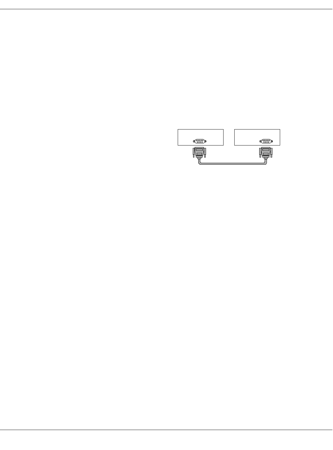
Connect the Hardware
1. Connect the 9-pin serial cable to the transmitter programming device.
On your PC, the port might be labeled “1” or “2”. If so, make a note of this
for later identifying the COM port used when running the software.
NOTE
NOTENOTE
NOTE
If the PC does not have a serial port, install USB-to-serial cable/adapter
(PN 2015891-001) and configure it using its accompanying software.
2. Replace the transmitter batteries with two new AA alkaline batteries.
3. Remove the transmitter’s leadwire set and the interface connector port
dust covers.
PC Programming Device
Draft
12 APEX, ApexPro, and ApexPro CH Transmitter Programming Instructions Revision A - Draft 7
2001989-135
Introduction
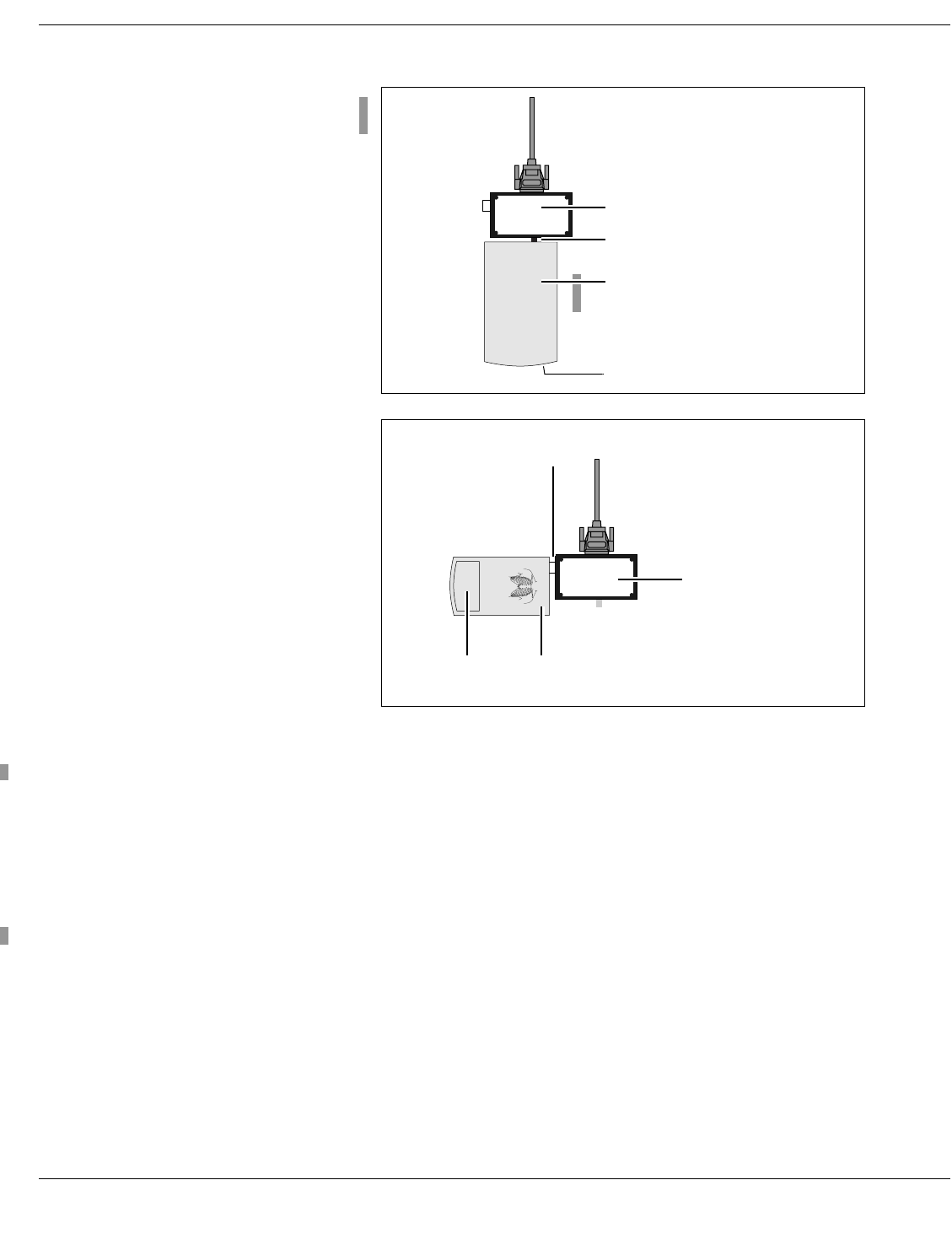
4. Insert the programming device connector into either of the transmitter’s
interface connector ports.
5. Turn the transmitter on:
For ApexPro and ApexPro CH, slide the battery cover over the
battery compartment. The LED lights will blink rapidly several
times and then slowly two times.
For Apex, close the battery cover. The LED lights will blink once and
then turn off.
Disconnect the Hardware
The transmitter should be disconnected and turned off when it is not in use.
1. Disconnect the transmitter from the programming device.
2. Turn off the transmitter by sliding the battery cover away from the
battery compartment. Doing this greatly extends the life of the batteries.
You may wish to remove the batteries and place them in a safe location.
3. (Optional) Disconnect the serial cable from the programming device and
from the PC.
ApexPro
Apex
ApexPro and ApexPro CH
Programming Device
010A
Transmitter’s interface port
Battery cover (on end)
ApexPro and
ApexPro CH
Apex
Apex
Transmitter
Programming Device
810A
Transmitter’s
interface port
Battery
cover
Apex
Draft
Revision A - Draft 7 APEX, ApexPro, and ApexPro CH Transmitter Programming Instructions 13
2001989-135
Introduction
Run the Apex & ApexPro Programming Box Software
Start the Software
1. Complete the procedure “Install the Programming Device” on page 9.
2. Complete the procedure “Connect the Hardware” on page 11.
3. Select Start > Programs > GE Medical Systems > Apex & ApexPro Tx
Config > Apex & ApexPro Tx Config to start the programming software.
You may also have a shortcut on the desktop called Apex & ApexPro Tx
Config to start the software.
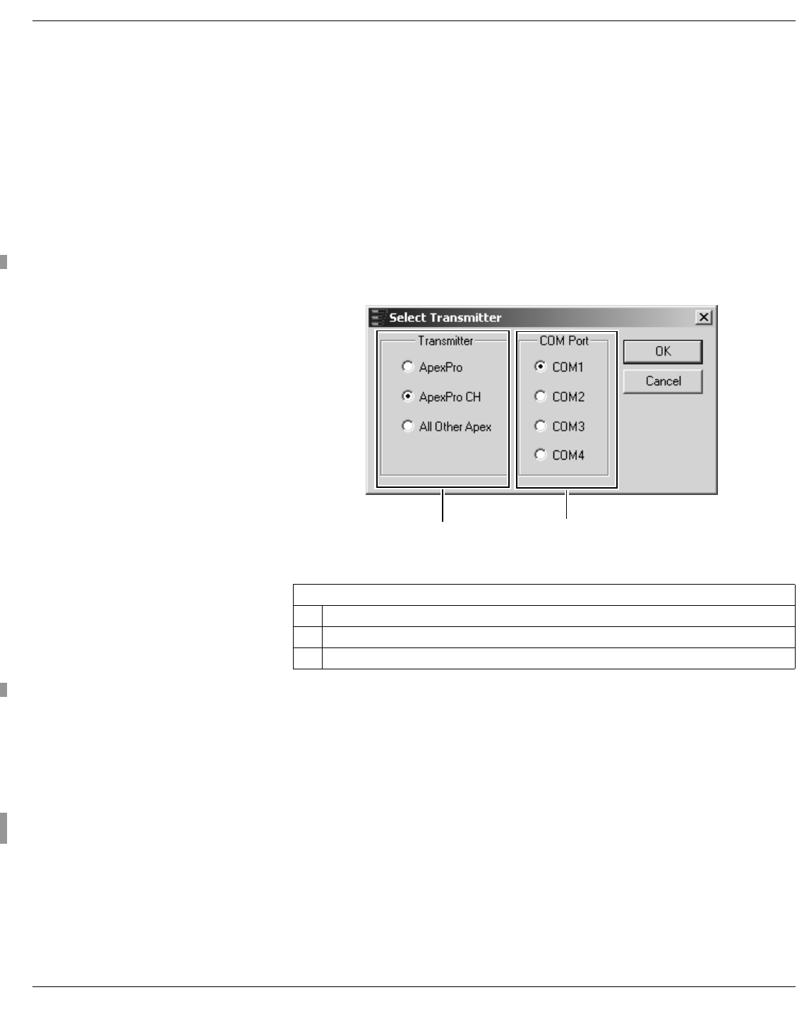
Select the Transmitter
Select the type of transmitter to be programmed and the communications
port, as described below.
1. Select the type of transmitter.
2. Select the correct COM Port.
If you know which COM Port is being used, select that. COM1 is most
common.
If you do not know the correct COM Port, select COM1 and then OK. If
this is not the correct COM Port, an error message No communication
from the transmitter will appear in the message area of the Program
ApexPro Transmitter window. You can then try COM2 and so on. See
“The Main Programming Window” on page 23 for explanation of that
window.
3. Select OK. The software remembers the settings.
Table 1. Select Transmitter
Ref Definition
AType of transmitter to be used
BCOM port on the computer to which the programming box cable is connected
A
105A
B
Draft
14 APEX, ApexPro, and ApexPro CH Transmitter Programming Instructions Revision A - Draft 7
2001989-135
Introduction
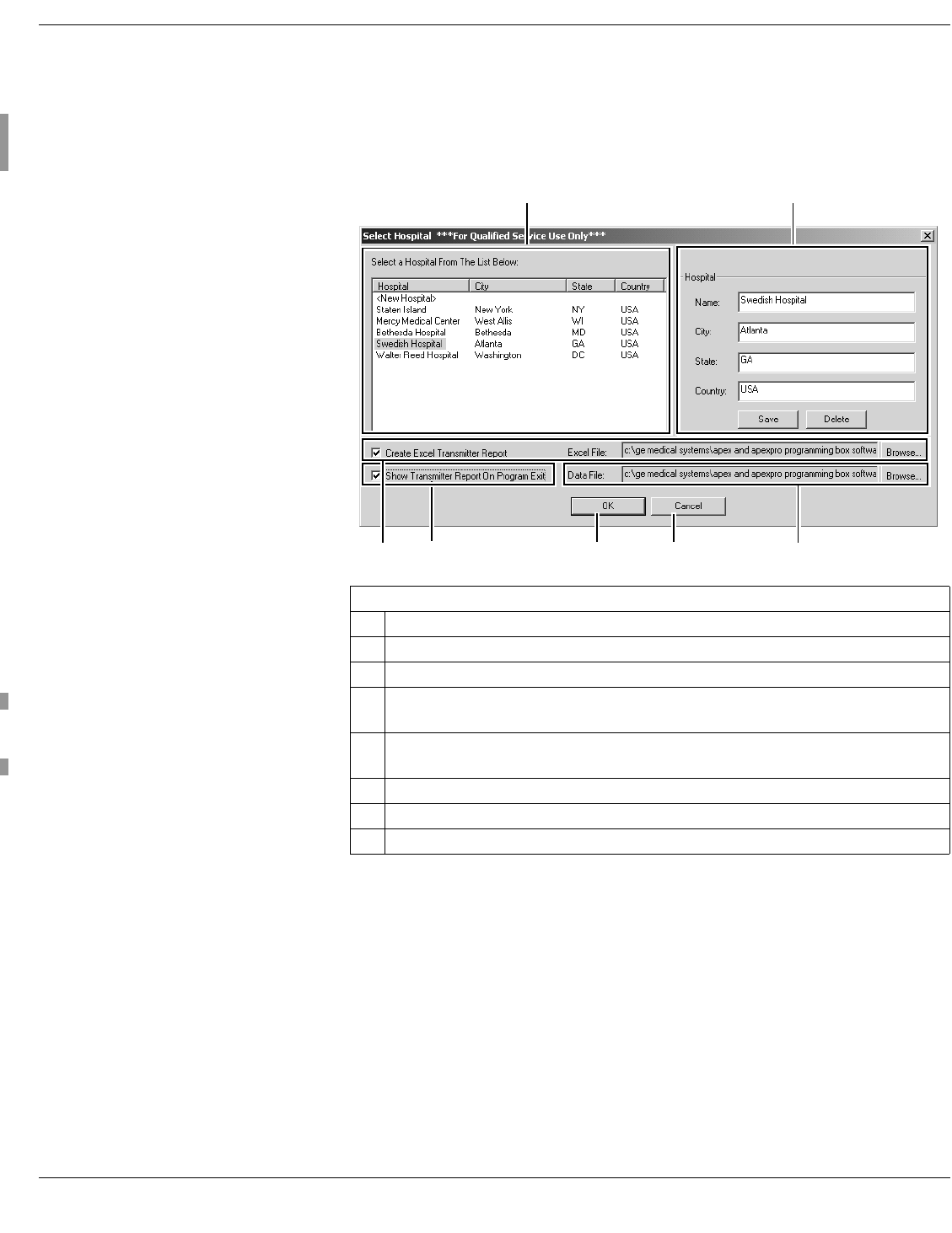
Select a Hospital
In the Select Hospital window, select the correct hospital. This information is
used for reporting purposes. A separate report is created for each hospital.
(See “Generate Reports” on page 15.) In this window you can also establish
the settings for a new hospital, or change the settings for a hospital already
listed.
1. Select the hospital for where the transmitter is located (A).
2. After selecting a hospital, its name and location will be displayed on the
right side of the window (B). This information is used for reporting
purposes.
3. If the correct hospital is not listed, select <New Hospital> at the top of
the list (A). Enter the name and location information for that hospital on
the right side of the window. Select Save. Do not select OK yet.
4. If the name and location displayed are not correct, make the appropriate
changes and select Save (B).
5. If there is a hospital in the list which is no longer needed, select that
hospital and select the Delete button (B).
Table 2. Select Hospital window
Ref Definition
AList of hospitals
BSpecific hospital name and location, with Save and Delete buttons
COption for displaying the Excel Transmitter report, with Browse button for changing the
location of the report
DOption to view the Transmitter Report (Ref. C above) when exiting the Programming Box
application, with Browse button for changing the location of the report
EOK button to process the Select Hospital data
FCancel button to exit the application
GFile to be used to save data for the hospital(s) and transmitters (See step 7 below.)
A B
FE
110A
DC G
Draft

Revision A - Draft 7 APEX, ApexPro, and ApexPro CH Transmitter Programming Instructions 15
2001989-135
Introduction
6. The software can automatically generate a Microsoft Excel report of all
channels, TTX IDs and frequencies to be used. (See “Excel Report” below
for details about generating this report.)
7. Identify the data file (G) to be used for storing all information about each
hospital and its transmitters. You can choose to store all information for
all transmitters programed at this hospital, or all transmitters ever
programmed.
This file stores all data about all transmitters.
You can copy the file and rename it for each individual hospital. You
might want to do this to send it to other personnel involved in the
installation.
Alternatively, you can keep all data for all hospitals in the same file.
This file is used to generate the Excel Transmitter Report.
8. Select OK (E) to continue programming transmitters. (If you select
Cancel (F), you will exit the application.)
9. The next configuration window, the Program ApexPro Transmitter
window, appears. Within 30 seconds, the transmitter’s settings display,
as described in “The Main Programming Window” on page 23.
Generate Reports
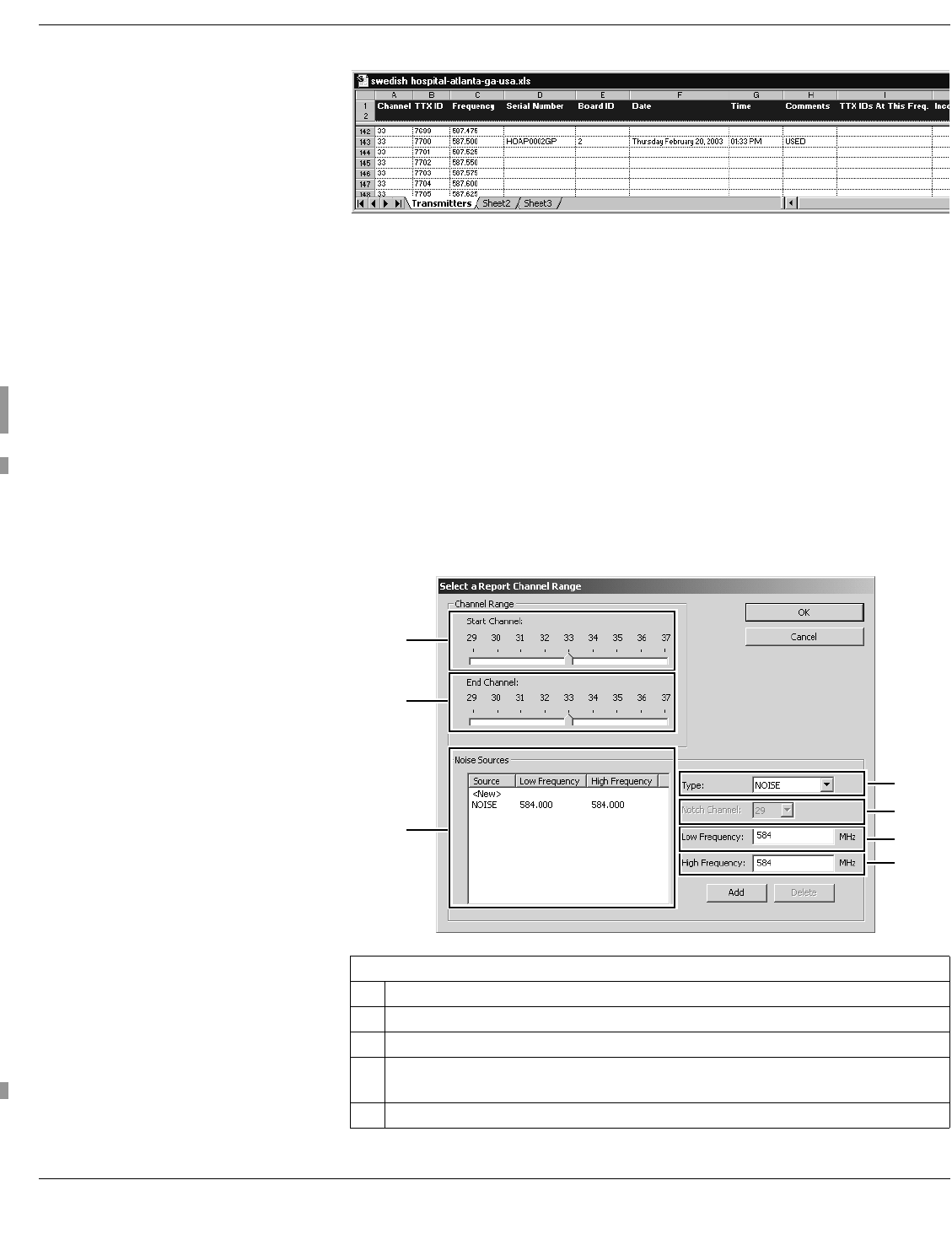
Excel Report The software can automatically generate a Microsoft Excel report of all
channels and TTX IDs used. For each channel and TTX ID within that
channel, this report lists:
Associated frequency
Serial number of transmitter programmed
Board ID
Date and time programmed
Comments you enter manually
TTX IDs at this frequency, if any are already programmed
Incompatible TTX IDs
Errors
This report is a separate Microsoft Excel report. It is displayed only if you
select the Exit button. It is not displayed if you quit the application by using
the close box.
You can edit any data in the report, notably the Comments section.
NOTE
NOTENOTE
NOTE
To keep any changes you make in the report, you should save it with a
different name. Otherwise, changes will be overwritten when you
regenerate the report.
Draft
16 APEX, ApexPro, and ApexPro CH Transmitter Programming Instructions Revision A - Draft 7
2001989-135
Introduction
This is a section of a sample report:
To generate the Transmitter Report:
1. Verify that Microsoft Excel is installed on the computer.
2. Verify that the In-Band Noise Test has been performed per details in the
ApexPro Antenna System Tests and Troubleshooting Instructions
manual. Have test results available.
3. In the Select Hospital window, select Create Excel Transmitter Report.
4. Accept the Excel file location named by default as shown in the Excel File
box (Ref. C in Table 2 on page 14), or navigate to another location using
the Browse button (C).
5. Select Show Transmitter Report On Program Exit (D).
6. When done programming the transmitters, select Exit.
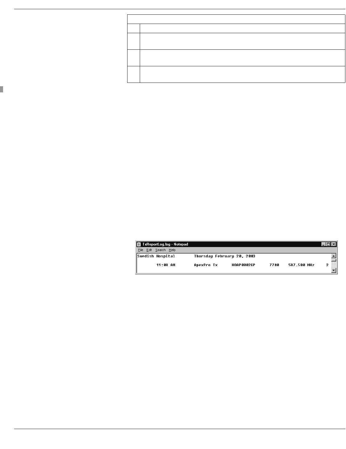
7. This window appears. Follow the instructions in Table 3 below.
Table 3. Select Channel Range window
Ref Definition
AStart Channel: Select the lowest channel to be used for analysis of the system
BEnd Channel: Select the highest channel to be used for analysis of the system
CList of all frequencies that can not be used for transmitter signals.
Enter References D, E, F and G and then select Add.
DType of signal blockage. Select Noise or Notch.
120A
A
F
E
125A
D
G
B
C
Draft
Revision A - Draft 7 APEX, ApexPro, and ApexPro CH Transmitter Programming Instructions 17
2001989-135
Introduction
8. Select OK. The Excel Transmitter Report generates and is displayed
when you exit the program.
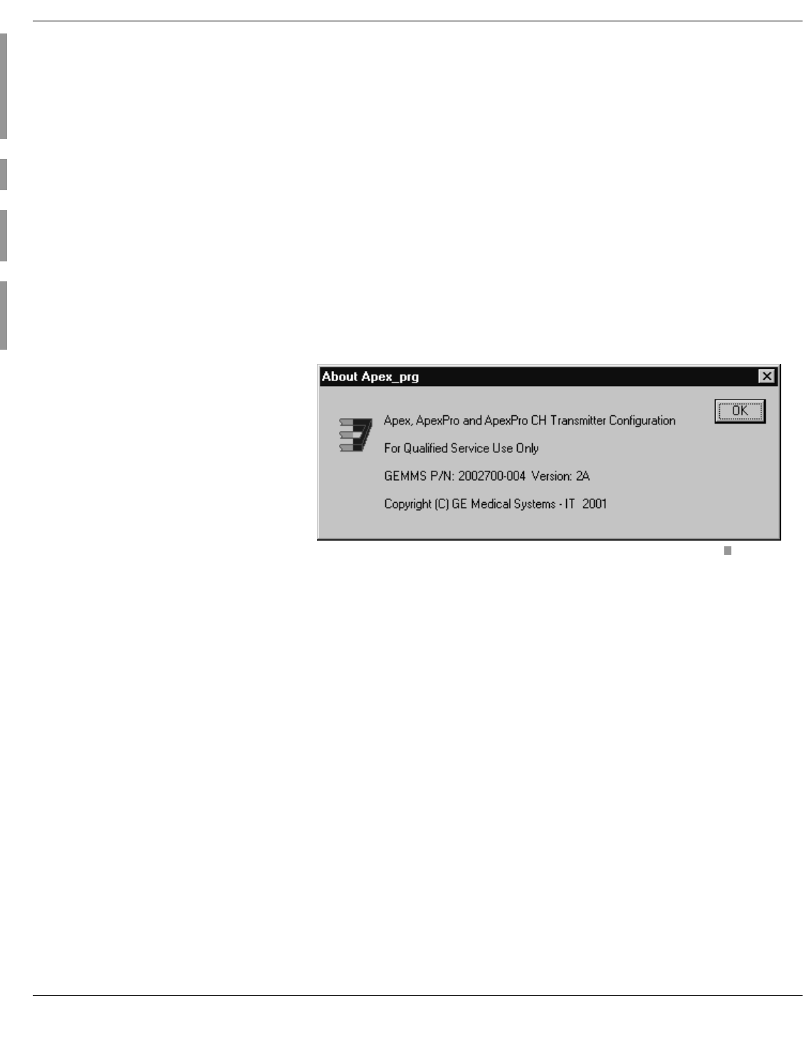
Log Report A separate text file called TxReportLog is automatically generated and
appears on your PC desktop.
This report lists:
All hospital names accessed
Date and time
Apex model
Serial number
TTX number
Frequency
Board ID
You can print this report and view information for each transmitter. This is a
section of a sample report:
EList of all channels that can be notched out if Type is Notch: Select the specific channel
to notch.
FLow frequency within the range: Accept the default lowest frequency of the range or specify
another frequency. This will create a slice of the channel’s full range.
GHigh frequency within the range: Accept the default highest frequency of the range or
specify another frequency. This will create a slice of the channel’s full range.
Table 3. Select Channel Range window
Ref Definition
130A
Draft
18 APEX, ApexPro, and ApexPro CH Transmitter Programming Instructions Revision A - Draft 7
2001989-135
Introduction
Getting Help
Apex and ApexPro Transmitter Programming Instructions Manual
You can access the Apex and ApexPro Transmitter Programming
Instructions manual by clicking the Help button on the Program ApexPro
Transmitter window, or pressing F1 on your keyboard. Doing so brings up
Adobe Acrobat Reader with a PDF file of this document. You can browse the
bookmarks, the table of contents or the document itself. You can also perform
Find and Search functions.
Flyover Windows The program also has informational flyovers that appear when you pause the
cursor over various areas of the program windows.
About the Apex Program Rightclick on the titlebar to display the About Apex_prg information window.
This window includes the part number and version of the transmitter
configuration.
385A
Draft

Revision A - Draft 7 APEX, ApexPro, and ApexPro CH Transmitter Programming Instructions 19
2001989-135
Introduction
Program Other Transmitters
You can program more than one transmitter without disconnecting the
programming box.
If the next transmitter is the same type (both Apex or both ApexPro), you do
not need to exit the Apex & ApexPro Tx Config software:
1. Disconnect the current transmitter.
2. Connect the next transmitter.
3. The software will detect the new configuration for you to view or change.
If the next transmitter is a different type (Apex vs. ApexPro):
1. Exit the Apex & ApexPro Tx Config software.
2. Disconnect the current transmitter.
3. Connect the next transmitter.
4. Restart the Apex & ApexPro Tx Config software.
5. Select the new type of transmitter. The COM Port should remain the
same. Select OK.
6. Select the hospital and then OK.
7. The software will detect the new configuration for you to view or change.
Draft

20 APEX, ApexPro, and ApexPro CH Transmitter Programming Instructions Revision A - Draft 7
2001989-135
Introduction
Draft

Revision A - Draft 7 APEX, ApexPro, and ApexPro CH Transmitter Programming Instructions 21
2001989-135
Apex Transmitter
2Apex Transmitter
Draft

22 APEX, ApexPro, and ApexPro CH Transmitter Programming Instructions Revision A - Draft 7
2001989-135
Apex Transmitter
For your notes
Draft
Revision A - Draft 7 APEX, ApexPro, and ApexPro CH Transmitter Programming Instructions 23
2001989-135
Apex Transmitter
Program the Transmitter’s Basic Functions
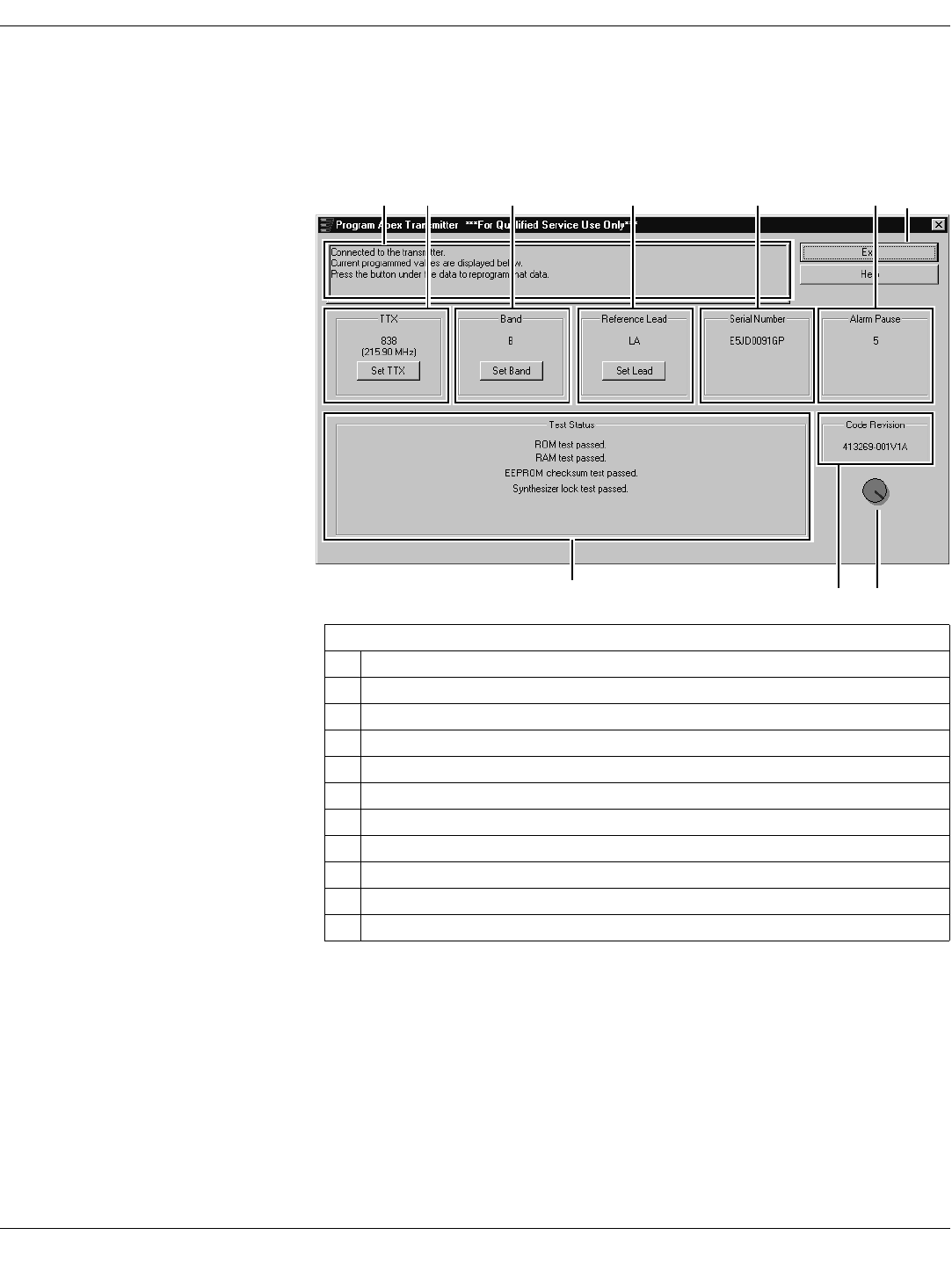
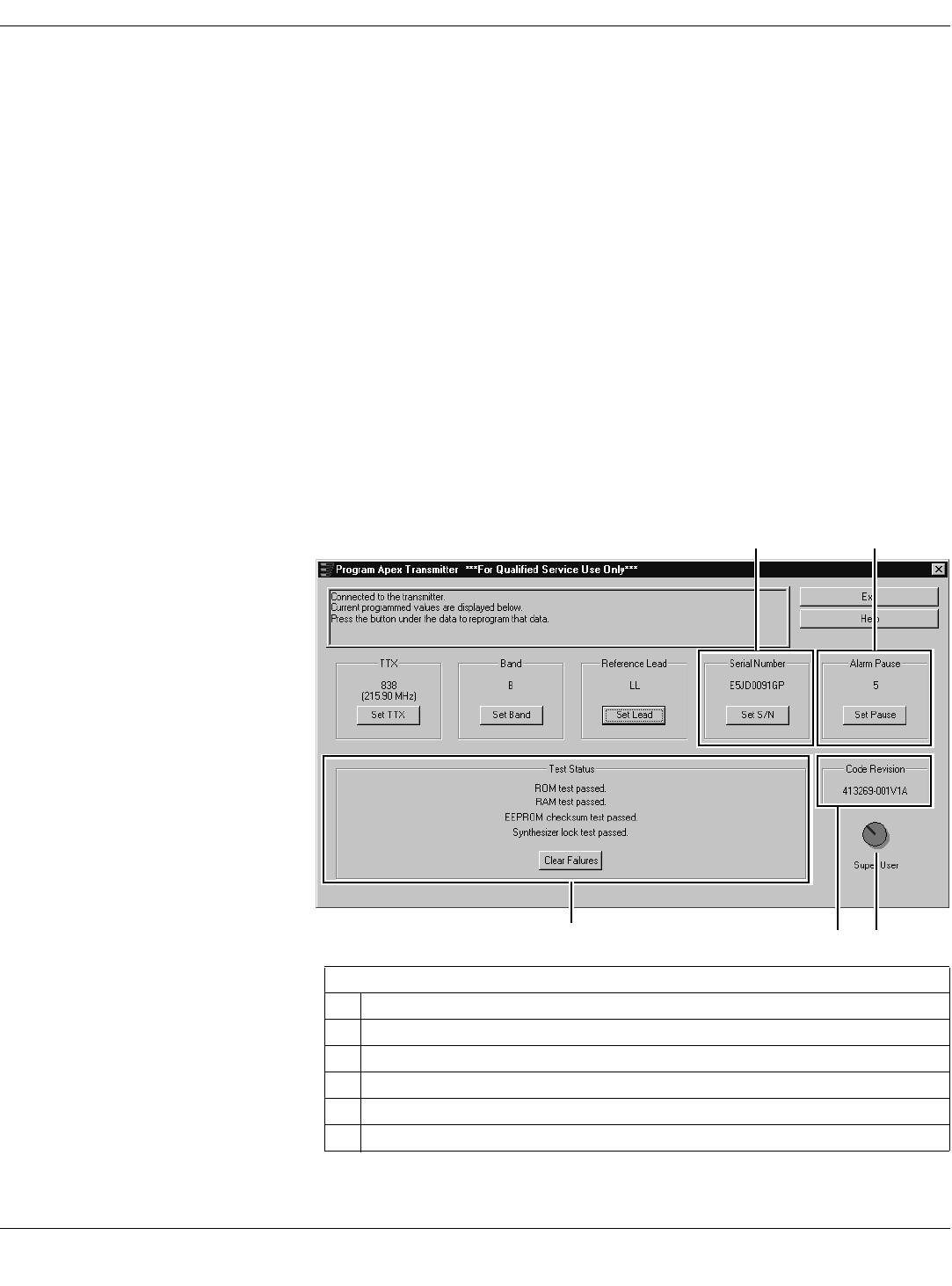
The Main Programming Window
The Program Apex Transmitter window displays various configuration
settings for the transmitter. These are described in the sections below.
Message Area
This area is used by the software for general status messages, operator
instructions and error messages.
NOTE
NOTENOTE
NOTE
If a message indicates No communication from the transmitter, refer to
“Programming Problems” on page 29.
TTX Number and Frequency Settings
The current TTX number which the transmitter is to use and the associated
frequency settings are displayed.
A G
HJ
B C E
705A
FD
I
Table 4. Program Apex Transmitter Window
Ref Definition
AMessage area for the programming application
BTTX number and frequency settings
CBand selection
DReference lead setting
ESerial number of the transmitter
FAlarm pause time
GExit program button
HCommunication status button
ICode version number
JTest status results
Draft
24 APEX, ApexPro, and ApexPro CH Transmitter Programming Instructions Revision A - Draft 7
2001989-135
Apex Transmitter
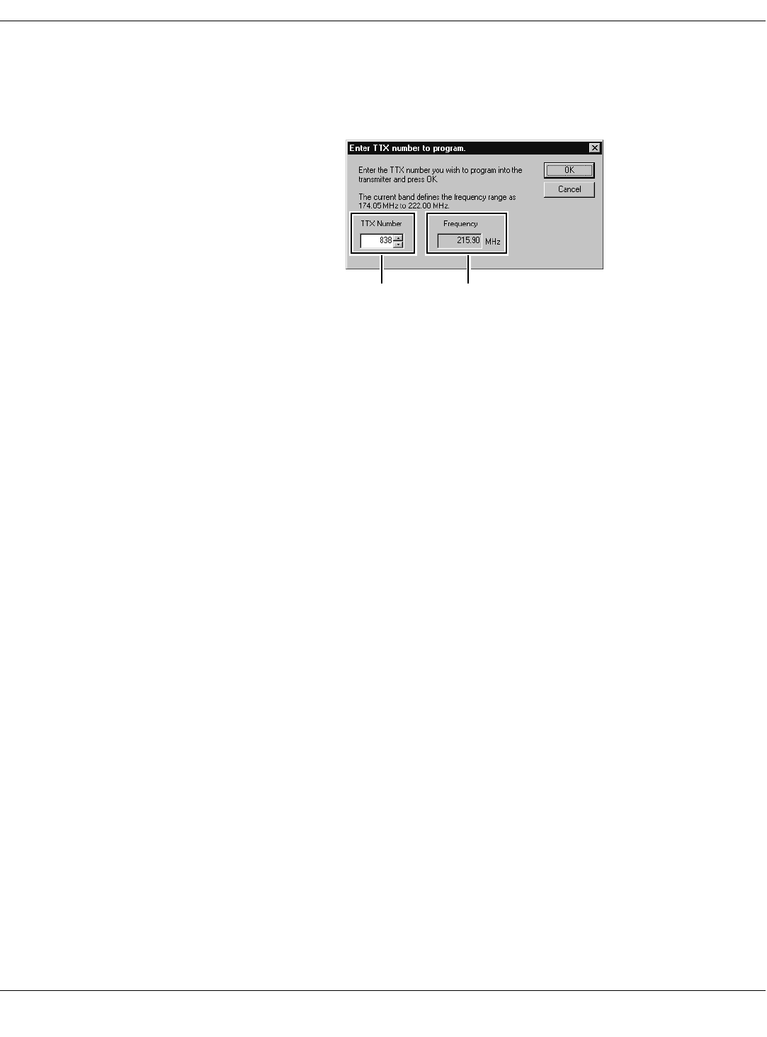
To change the settings:
1. Select the Set TTX button, reference B in “Program Apex Transmitter
Window” on page 23.
2. Another window appears.
3. This window allows you to:
a – Change the TTX Number: Either use the up- and down-arrows to
scroll to the desired TTX number or highlight and type in the number
to use. The frequency changes automatically as you change the TTX
Number.
b – View the associated Frequency in MHz.
NOTE
NOTENOTE
NOTE
Select a frequency that is within the frequency range allowed by your
location. Operating outside of the allowed frequency range may cause
interference problems or data dropout.
Some frequencies are reserved. If the TTX number you choose has a
reserved frequency, this will be indicated as RESERVED in the
frequency display. See the ApexPro Telemetry Transmitter Service
Manual for a list of TTX numbers, associated frequencies and
reserved frequencies.
4. Select OK to save your changes or Cancel to revert to the original
settings.
5. Update the “TTX Frequency Chart” in the ApexPro Telemetry
Transmitter Service Manual to identify changes to the TTX numbers and
the frequencies.
6. Remove the existing label located on the back of the transmitter, select
the appropriate TTX label from the label sheet and apply it to the
transmitter.
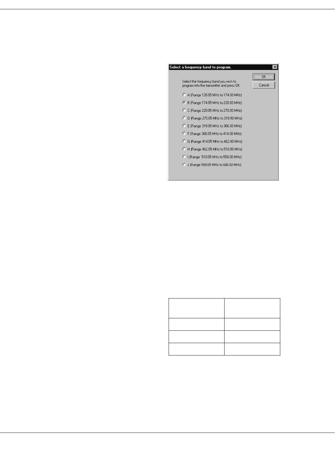
Band Setting
The band setting determines the range of frequencies within which the
transmitter is to operate. The band for each transmitter is identified by a
label found in the battery compartment.
a b
715A
Draft
Revision A - Draft 7 APEX, ApexPro, and ApexPro CH Transmitter Programming Instructions 25
2001989-135
Apex Transmitter
To set the band:
1. Select the Set Band button, reference C in “Program Apex Transmitter
Window” on page 23.
2. Another window appears. Select the correct band. (Selecting one
eliminates the others.) Select OK.
3. The change is shown on the Program Apex Transmitter window.
Reference Lead Setting
For 5- or 6-Lead Cables The reference lead setting has no effect when 5- or 6-lead cables are used.
For 5- or 6-lead cables, the reference lead defaults to RL.
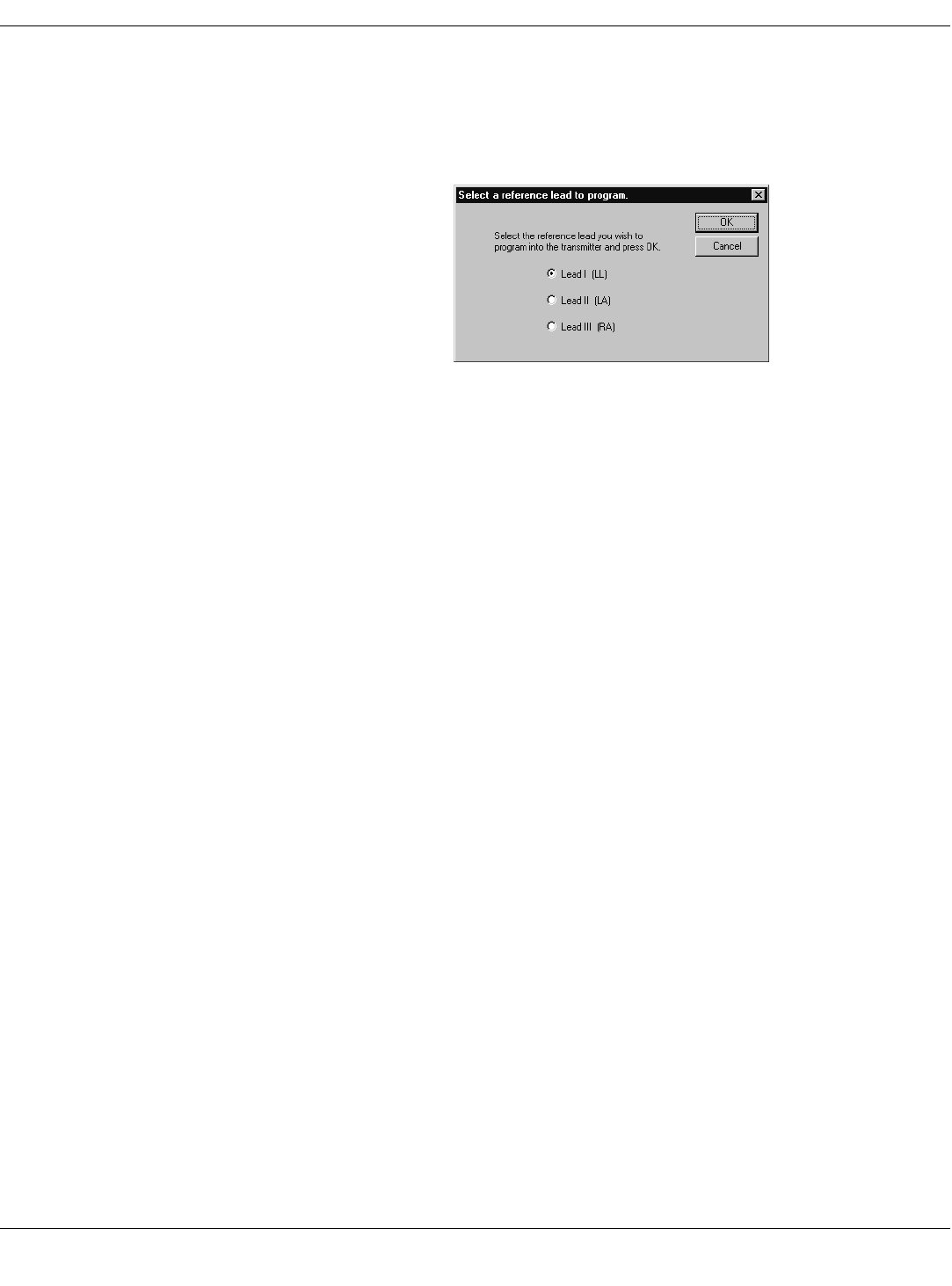
For 3-Lead Cables For 3-lead cables, one of the lead wires (LL, LA, or RA) is used to connect the
reference voltage to the patient. Selection of the reference lead determines
which ECG waveform will be displayed at the CIC, according to the table
below.
805A
Select this
reference lead... to view this
waveform at the CIC
LL (left leg) Lead I
LA (left arm) Lead II
RA (right arm) Lead III
Draft
26 APEX, ApexPro, and ApexPro CH Transmitter Programming Instructions Revision A - Draft 7
2001989-135
Apex Transmitter
To change the setting:
1. Select the Set Lead button, reference D in “Program Apex Transmitter
Window” on page 23.
2. Another window appears. Select the correct lead. (Selecting one
eliminates the others.) Select OK.
3. The change is shown on the Program Apex Transmitter window.
Alarm Pause Setting
. The purpose of the alarm pause setting is to allow clinicians to adjust the
transmitter and/or the patient without setting off alarms. The alarm pause
setting is an amount of time, in minutes, during which alarms will not
activate. After this time has elapsed, the alarm pause will automatically be
deactivated and the transmitter will resume normal operation. You can
manually turn off the alarm pause at any time by pressing Verify Leads
and Graph at the same time.
NOTE
NOTENOTE
NOTE
Activation and deactivation of the alarm pause is done on the transmitter
itself. The setting in the software only sets the number of minutes to wait
until the alarm pause times out.
To change the setting, see “Change Alarm Pause Setting” on page 27.
Firmware Code Revision Number
This is a display of the version number of the transmitter’s firmware.
Exit Button
When you are done with changing all configuration settings, select the Exit
button (reference F in “Program Apex Transmitter Window” on page 23) to
save the settings and exit the program.
215A
Draft
Revision A - Draft 7 APEX, ApexPro, and ApexPro CH Transmitter Programming Instructions 27
2001989-135
Apex Transmitter
Perform Advanced Functions
Perform Advanced Programming
Communication Status Button The Communication status button (reference C in “Appendix 2: Access Apex
Technical Functions” on page 31) revolves clockwise to indicate that the
hardware (transmitter, programming device, and the PC) is properly
connected and the software is processing normally.
In addition, by clicking on this button, authorized personnel can access the
advanced functions described in this section. A password is needed to access
these functions.
Set Serial Number This is a display of the serial number of the specific transmitter that uses
this software.
Whenever a transmitter is replaced, you must enter the new transmitter’s
serial number. You must also identify the level of software to be used with
the new transmitter.
To change the settings:
1. Access the high-level technical functions of the software as described in
“Access the Super User Mode” on page 31.
2. Select the Set S/N button, reference A in “Program Apex Transmitter
Technical Functions Window” on page 31.
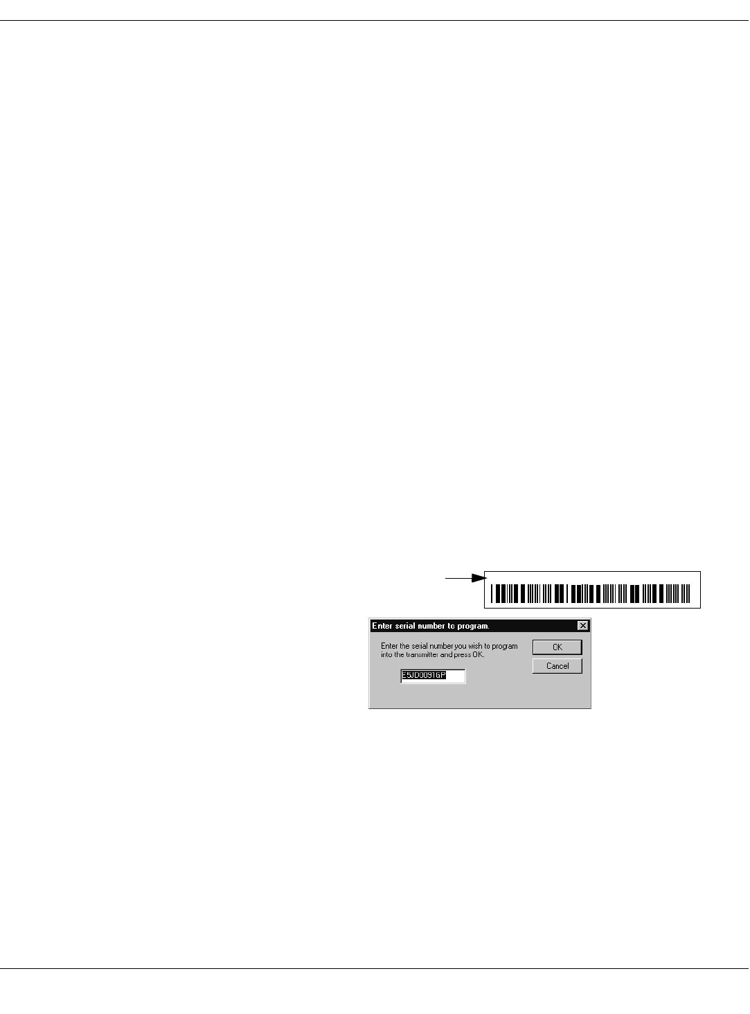
3. A window appears asking for the new serial number. Enter the new
serial number, found on the label on the back of the transmitter. (You
must use upper-case.)
4. Select OK to proceed with the change. (Select Cancel to make no change.)
5. The change is shown on the Program Apex Transmitter window.
Change Alarm Pause Setting
. See “Alarm Pause Setting” on page 26 for a description of this setting.
To change the setting:
510A
E5JD0091GP MILWAUKEE, WI USA
Serial number on transmitter
Draft

28 APEX, ApexPro, and ApexPro CH Transmitter Programming Instructions Revision A - Draft 7
2001989-135
Apex Transmitter
1. Access the high-level technical functions of the software as described in
“Access the Super User Mode” on page 31.
2. Select the Set Pause button (reference B in “Program Apex Transmitter
Technical Functions Window” on page 31.)
3. Another window appears.
4. Set the correct number of minutes. Either use the up- and down-arrows
to scroll to the desired number or highlight and type in the number to
use.
5. Select OK.
6. The change is shown on the Program Apex Transmitter window.
Monitor the Status of Transmitter Tests
Transmitter tests run whenever the transmitter is powered up. You can view
the test results with the Apex & ApexPro Tx Config software. The results
shown indicate pass-or-fail status for these tests:
ROM — Read-Only Memory. If this test fails, the ROM needs to be
replaced.
RAM — Random-Access Memory. If this test fails, the RAM needs to be
replaced.
EEPROM Checksum — Indicates whether the transmitter firmware is
valid or is corrupt.
Synthesizer Lock — Shows the current status of the phase lock loop in
the transmitter. This indicates whether or not the transmitter is
operating at its programmed frequency. Failure of this test indicates that
this transmitter could be operating at a different frequency and could be
causing interference with another transmitter programmed to that other
frequency. If this is the case, this transmitter should be removed from
service until the problem is corrected. Refer to “Test Status Failures” on
page 30.
If any test has failed:
1. Access the high-level technical functions of the software as described in
“Access the Super User Mode” on page 31.
2. Select the Clear Failures button (reference E in “Program Apex
Transmitter Technical Functions Window” on page 31.)
If any tests fail again, see “Appendix 1: Apex Troubleshooting” on page 29.
220A
Draft
Revision A - Draft 7 APEX, ApexPro, and ApexPro CH Transmitter Programming Instructions 29
2001989-135
Apex Transmitter
Apex Appendices
Appendix 1: Apex Troubleshooting
LED Status Problems
Programming Problems
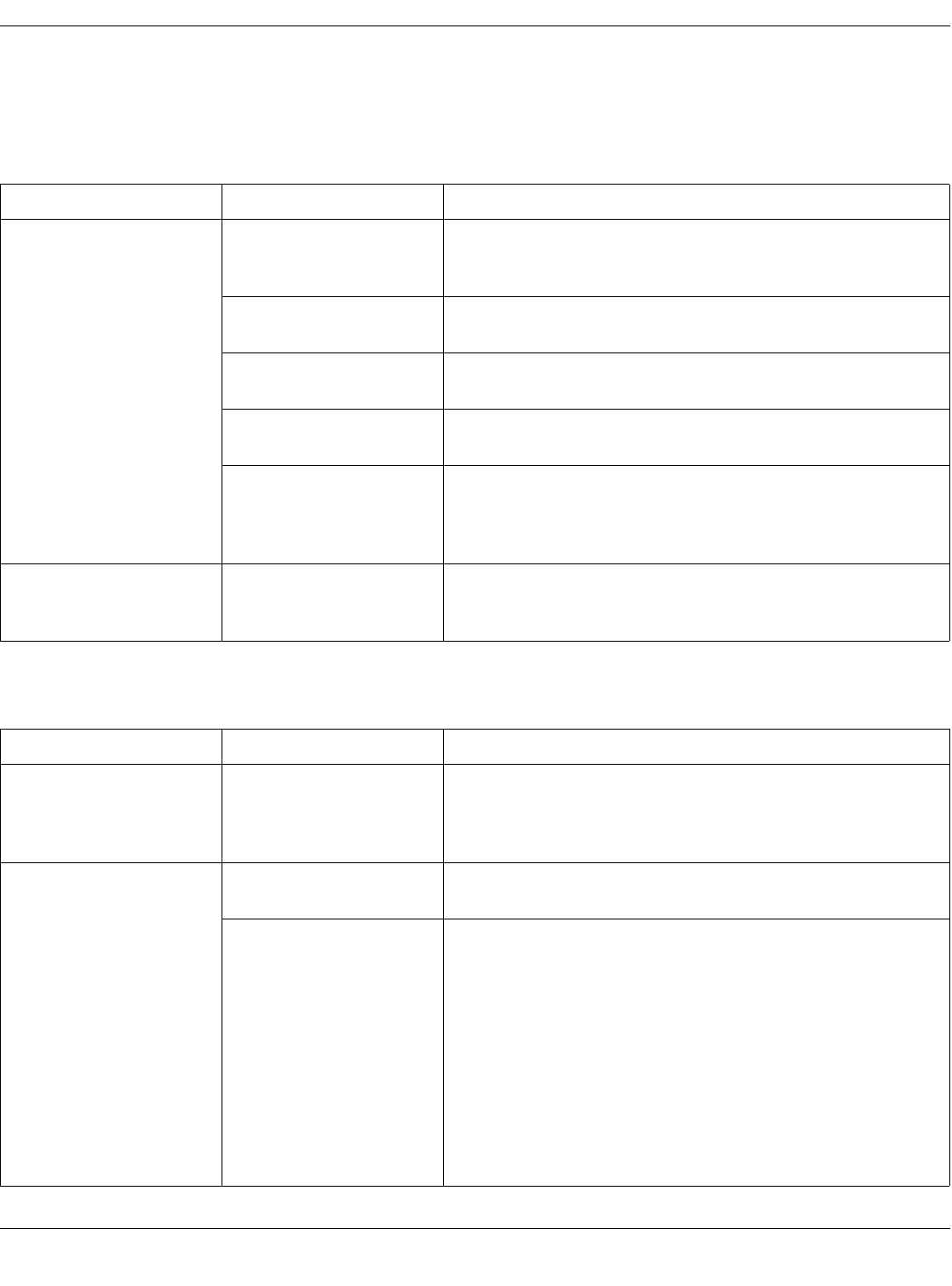
Condition Possible Cause Possible Actions
No lights are blinking. Normal status when hardware
is properly connected and the
software is running.
No action needed.
Hardware is not connected
properly. Check the hardware connections as described in “Connect the Hardware” on
page 11.
Software is not installed. Install the Apex & ApexPro Tx Config software as described in “Install
the Programming Device” on page 9.
Software is not running. Start the Apex & ApexPro Tx Config software as described in “Run
the Apex & ApexPro Programming Box Software” on page 13.
Batteries do not have enough
power. Replace the batteries:
1. Disconnect the transmitter from the programming device.
2. Replace the transmitter batteries with two new AA alkaline batteries.
3. Reconnect the transmitter to the programming device.
All lights blink once and then
turn off. Normal status when hardware
has just been properly
connected.
No action needed.
Condition Cause Possible Actions
Unable to display or program
the transmitter settings Batteries do not have enough
power. Replace the batteries:
1. Disconnect the transmitter from the programming device.
2. Replace the transmitter batteries with two new AA alkaline batteries.
3. Reconnect the transmitter to the programming device.
Message indicates No
communication from the
transmitter:
Hardware is not connected
properly. Check the hardware connections as described in “Connect the Hardware” on
page 11.
Incorrect COM port was
selected. 1. Exit this window. (Reference G in “Program Apex Transmitter Window”
on page 23.)
2. Restart Apex & ApexPro Tx Config: In your PC’s Start menu,
select Programs > GE Medical Systems > Apex & ApexPro
Tx Config > Apex & ApexPro Tx Config.
3. In the Select Transmitter window, choose a different COM Port
from what you selected before. Select OK.
4. Repeat steps 1 through 3 until a connection is established and the
message area indicates Connected to the transmitter.
5. If the transmitter still is not working after trying all of the COM ports, refer
to other sections of this appendix.
Draft
30 APEX, ApexPro, and ApexPro CH Transmitter Programming Instructions Revision A - Draft 7
2001989-135
Apex Transmitter
Test Status Failures
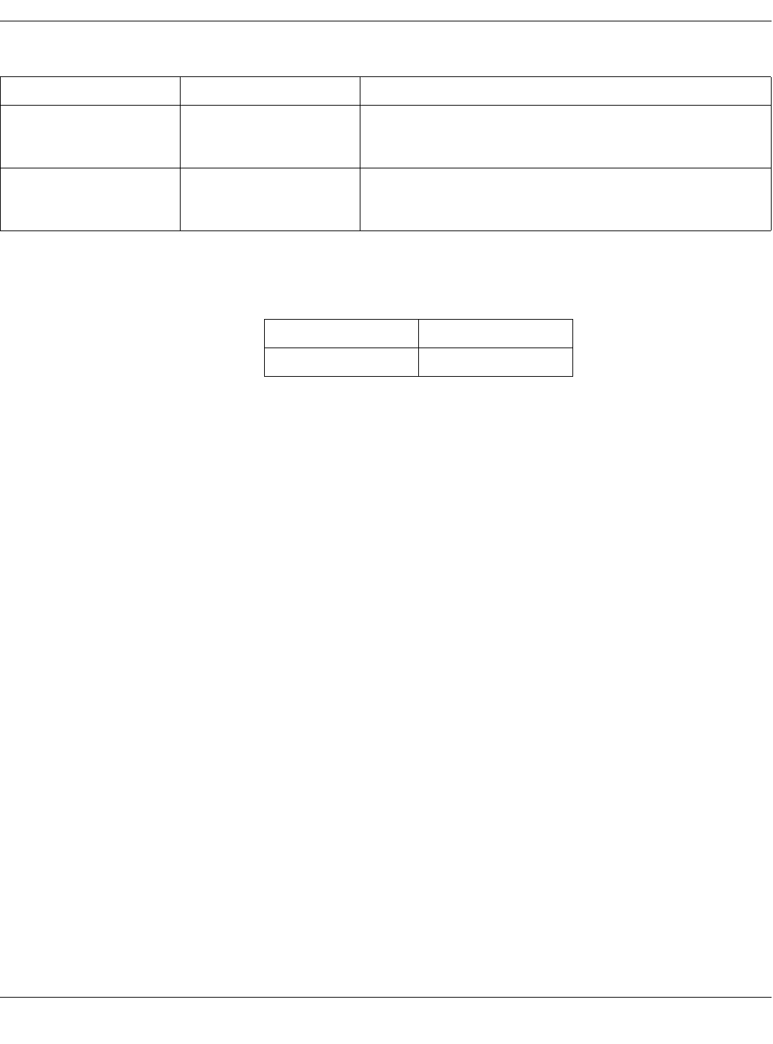
Technical Support If the above information does not resolve your problem, call:
Condition Possible Cause Possible Actions
EEPROM Checksum indicates
fail status. The transmitter firmware is
incorrect or corrupt. Cycle the power on the transmitter. If the failure occurs again, re-program
the transmitter’s functions and cycle the power on the transmitter. If the
failure still occurs, contact Technical Support. (See below.)
Synthesizer Lock indicates fail
status. The transmitter is currently
unable to operate at its
programmed frequency.
Try programming the transmitter to another frequency. If the failure still
occurs, contact Technical Support. (See below.)
U.S. and Canada 800-558-7044
Other countries 561-575-5000
Draft
Revision A - Draft 7 APEX, ApexPro, and ApexPro CH Transmitter Programming Instructions 31
2001989-135
Apex Transmitter
Appendix 2: Access Apex Technical Functions
Several high-level technical functions are available by following the steps in
“Access the Super User Mode” below. Technical functions are password-
protected to prevent accidental use.
Requirements You must have the items identified in “Hardware Requirements for the
Programming Device” on page 9.
Access the Super User Mode Start the software as in “Run the Apex & ApexPro Programming Box
Software” on page 13 and then access the Super User mode of the software
by following these steps:
1. Select the Communication status button, reference H in “Program Apex
Transmitter Window” on page 23 and reference C in “Program Apex
Transmitter Technical Functions Window” below.
2. Type the password mms_aps.
3. Select OK.
4. The Program Apex Transmitter window will display additional features.
5. To exit the Super User mode, select the Communication status button
again.
710A
CE
A B
D
Table 5. Program Apex Transmitter Technical Functions Window
Ref Definition
ASerial number
BAlarm pause time
CCommunication status button
DCode version number
ETest Status results
Draft

32 APEX, ApexPro, and ApexPro CH Transmitter Programming Instructions Revision A - Draft 7
2001989-135
Apex Transmitter
Appendix 3: Apex TTX Labels
Transmitters used with Apex systems require TTX labels that have this
format:
XXX
TTX
Draft

Revision A - Draft 7 APEX, ApexPro, and ApexPro CH Transmitter Programming Instructions 33
2001989-135
ApexPro CH Transmitter
3ApexPro CH Transmitter
Draft

34 APEX, ApexPro, and ApexPro CH Transmitter Programming Instructions Revision A - Draft 7
2001989-135
ApexPro CH Transmitter
For your notes
Draft
Revision A - Draft 7 APEX, ApexPro, and ApexPro CH Transmitter Programming Instructions 35
2001989-135
ApexPro CH Transmitter
Program the Transmitter’s Basic Functions
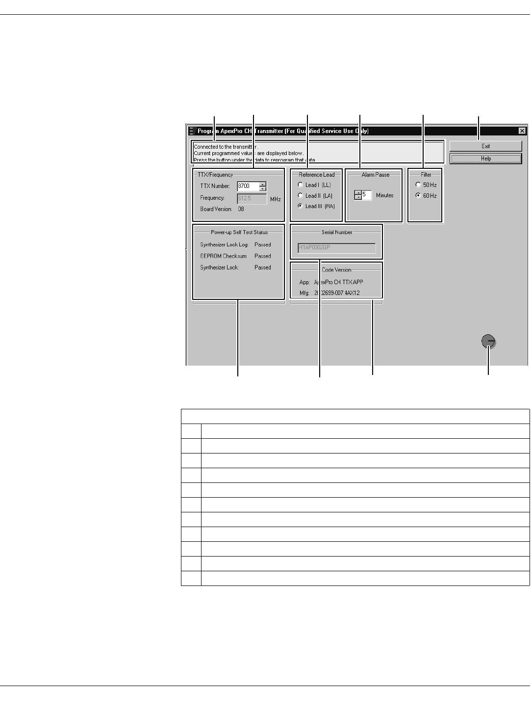
The Main Programming Window
The Program ApexPro CH Transmitter window displays various
configuration settings for the transmitter. These are described in the
sections below.
Table 6. Program ApexPro CH Transmitter Window
Ref Definition
AMessage area for the programming application
BTTX number and frequency settings
CReference lead setting
DAlarm pause setting
EFilter setting
FExit program button
GPower-up self-test status results
HSerial number of the transmitter
ICode part/version numbers
JCommunication status button
A F
JIHG
B C D E
305A
Draft
36 APEX, ApexPro, and ApexPro CH Transmitter Programming Instructions Revision A - Draft 7
2001989-135
ApexPro CH Transmitter
Message Area
This area is used by the software for general status messages, operator
instructions and error messages.
NOTE
NOTENOTE
NOTE
If a message indicates No communication from the transmitter, refer to
“Programming Problems” on page 50.
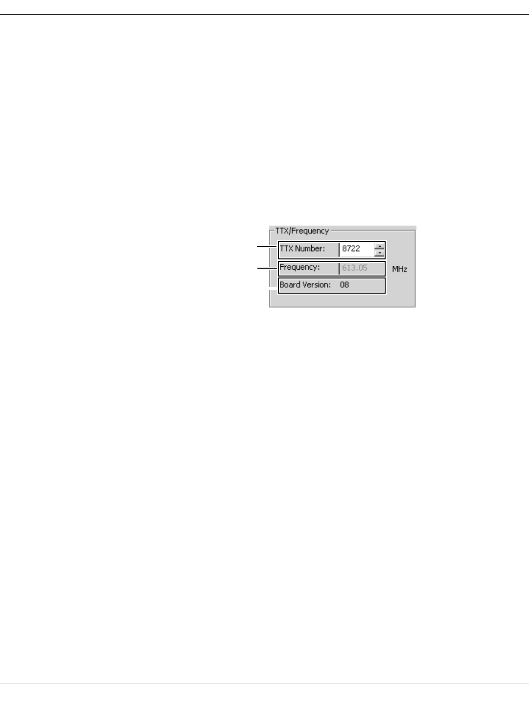
TTX Number and Frequency Settings
The current TTX number and associated frequency settings are displayed.
The board version, important to a technician, is also displayed. This window
allows you to change the TTX Number.
To change the settings use the up- and down-arrows to scroll to the desired
TTX number, or highlight the field and type the number to use. The
frequency changes automatically as you change the TTX Number.
NOTE
NOTENOTE
NOTE
Select a frequency that is within the frequency range allowed by your
location. Operating outside of the allowed frequency range may cause
interference problems or data dropout.
Some frequencies are reserved and cannot be used. If the TTX number
you choose has a reserved frequency, this will be indicated as
RESERVED in the frequency display. See the ApexPro Telemetry
Transmitter Service Manual for a list of TTX numbers, associated
frequencies and reserved frequencies.
Update the “TTX Frequency Chart” in the ApexPro Telemetry Transmitter
Service Manual to identify changes to the TTX numbers and the frequencies.
Select the appropriate TTX label for ApexPro CH V2 from the label sheet and
apply it to the transmitter inside the label depression located on the back of
the transmitter. (See “Appendix 3: ApexPro CH TTX Labels and
Frequencies” on page 56 for applicable label part numbers.)
a
b
c
310A
Draft
Revision A - Draft 7 APEX, ApexPro, and ApexPro CH Transmitter Programming Instructions 37
2001989-135
ApexPro CH Transmitter
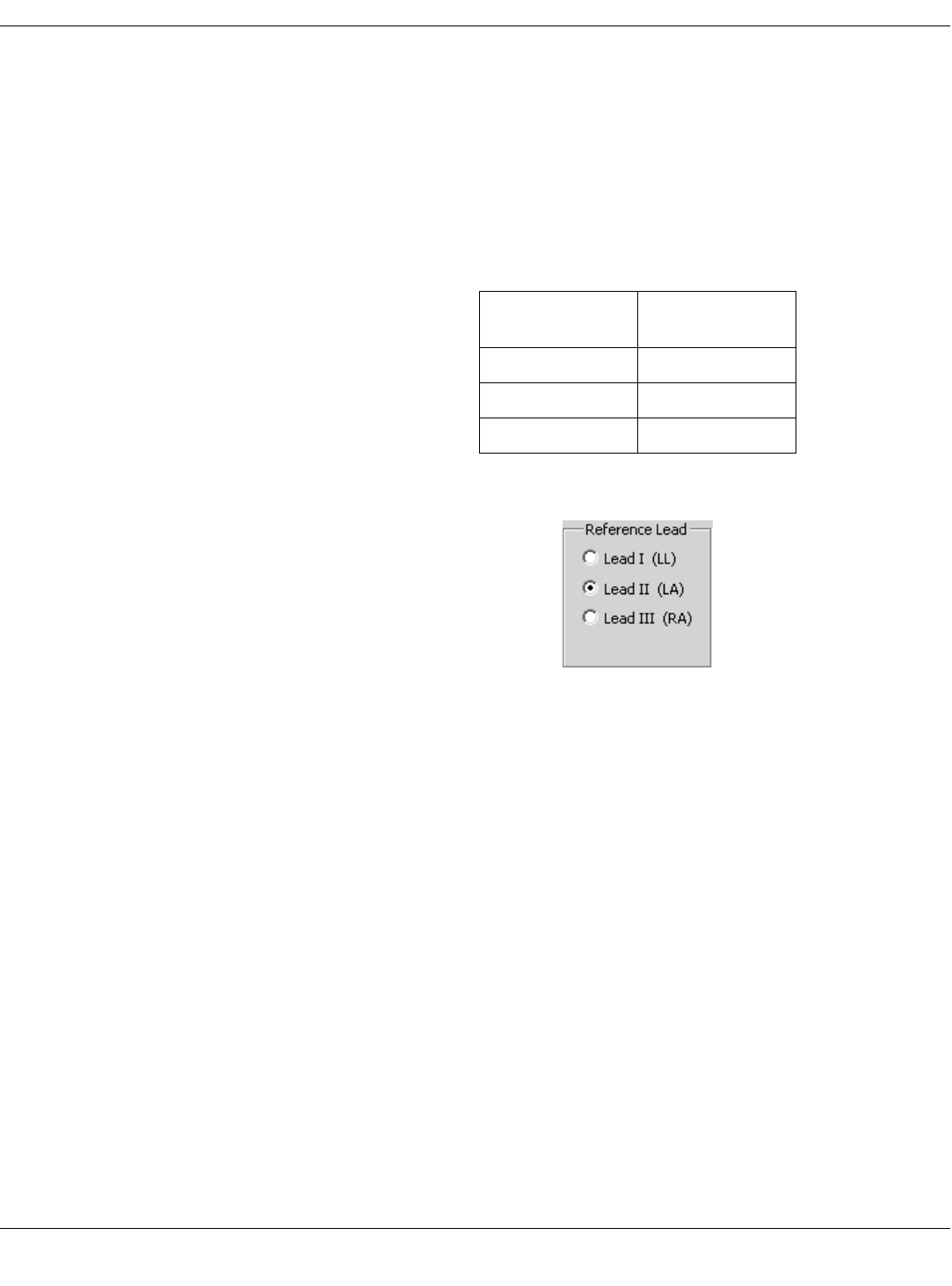
Reference Lead Setting
For 5- or 6-Lead Cables The reference lead setting has no effect when 5- or 6-lead cables are used.
For 5- or 6-lead cables, the reference lead defaults to RL.
For 3-Lead Cables For 3-lead cables, one of the lead wires (LL, LA, or RA) is used to connect the
reference voltage to the patient. Selection of the reference lead determines
which ECG waveform will display at the CIC.
Select the desired Reference Lead.
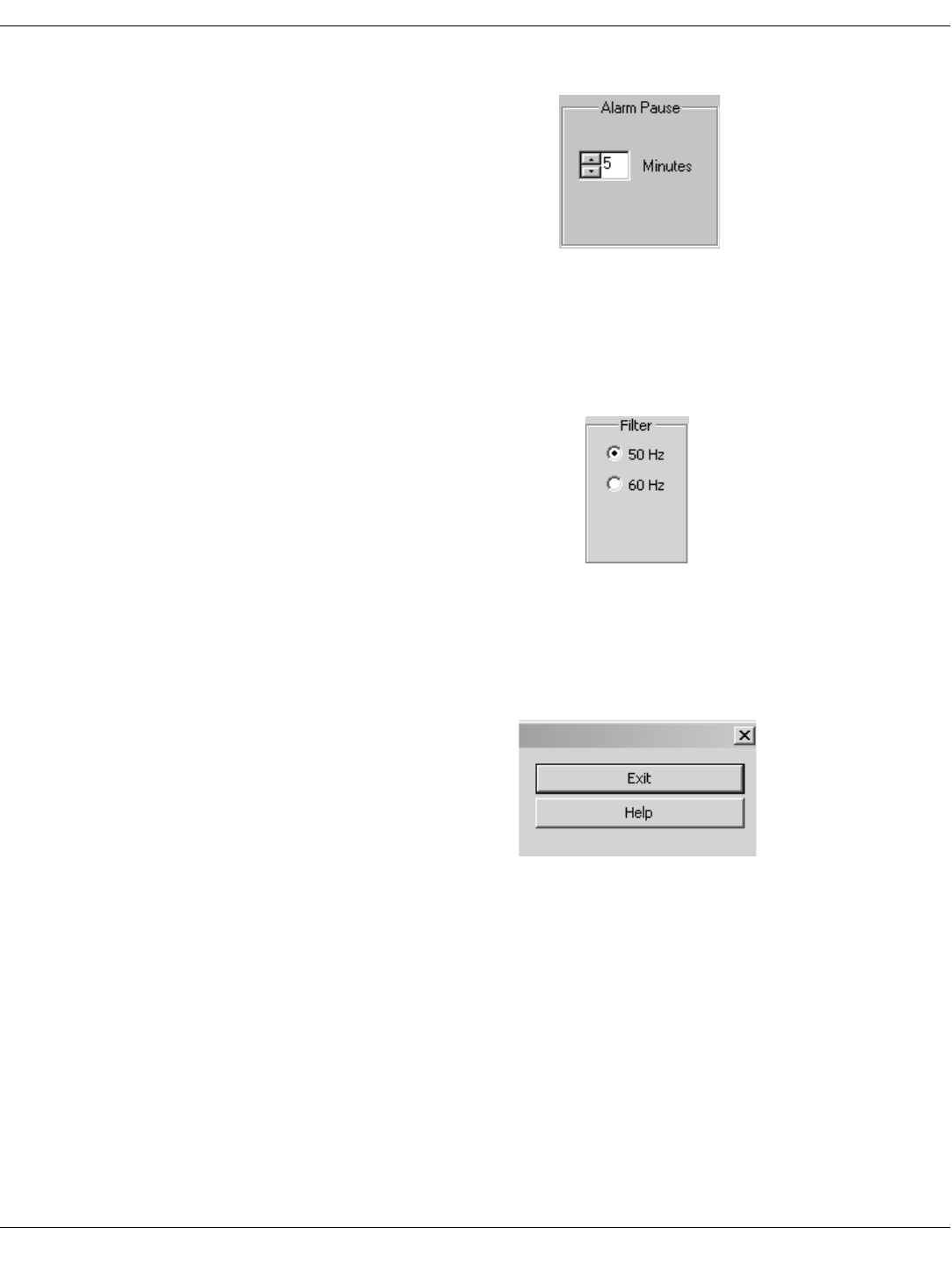
Alarm Pause Setting
The purpose of the alarm pause setting is to allow clinicians to adjust the
transmitter and/or the patient without setting off alarms. The alarm pause
setting is an amount of time, in minutes, during which alarms will not
activate. After this time has elapsed, the alarm pause will automatically be
deactivated and the transmitter will resume normal operation. You can
manually turn off the alarm pause at any time by pressing Verify Leads
and Graph at the same time.
NOTE
NOTENOTE
NOTE
Activation and deactivation of the alarm pause is done on the
transmitter itself. The setting in the software only sets the number of
minutes to wait until the alarm pause times out.
Select this
reference lead... to view this
waveform at the CIC
Lead I LL (left leg)
Lead II LA (left arm)
Lead III RA (right arm)
315A
Draft
38 APEX, ApexPro, and ApexPro CH Transmitter Programming Instructions Revision A - Draft 7
2001989-135
ApexPro CH Transmitter
To change the settings use the up- and down-arrows to scroll to the desired
alarm pause, or highlight the field and type the number of minutes to pause.
Filter Setting
The filter setting is the frequency of the power lines for the country in which
the transmitter will be used, either 50 or 60 Hz. In the United States, this is
typically 60 Hz. For most other countries, this is typically 50 Hz. Select the
appropriate setting.
Exit Button
When you are done with changing all configuration settings, select the Exit
button (reference F in “Program ApexPro CH Transmitter Window” on
page 35) to save the settings and exit the program.
Help
At any time, you can access Help by clicking the Help button (see figure
above) or pressing F1 on your keyboard which brings up Adobe Acrobat
Reader with a PDF file of this document. You can browse the bookmarks, the
table of contents, or the document itself. You can perform Find and Search
functions also.
The program also has short informational pop-ups that appear when you
pause the cursor over various areas of the program windows.
320A
325A
135A
Draft
Revision A - Draft 7 APEX, ApexPro, and ApexPro CH Transmitter Programming Instructions 39
2001989-135
ApexPro CH Transmitter
View Transmitter Diagnostics
View Test Results
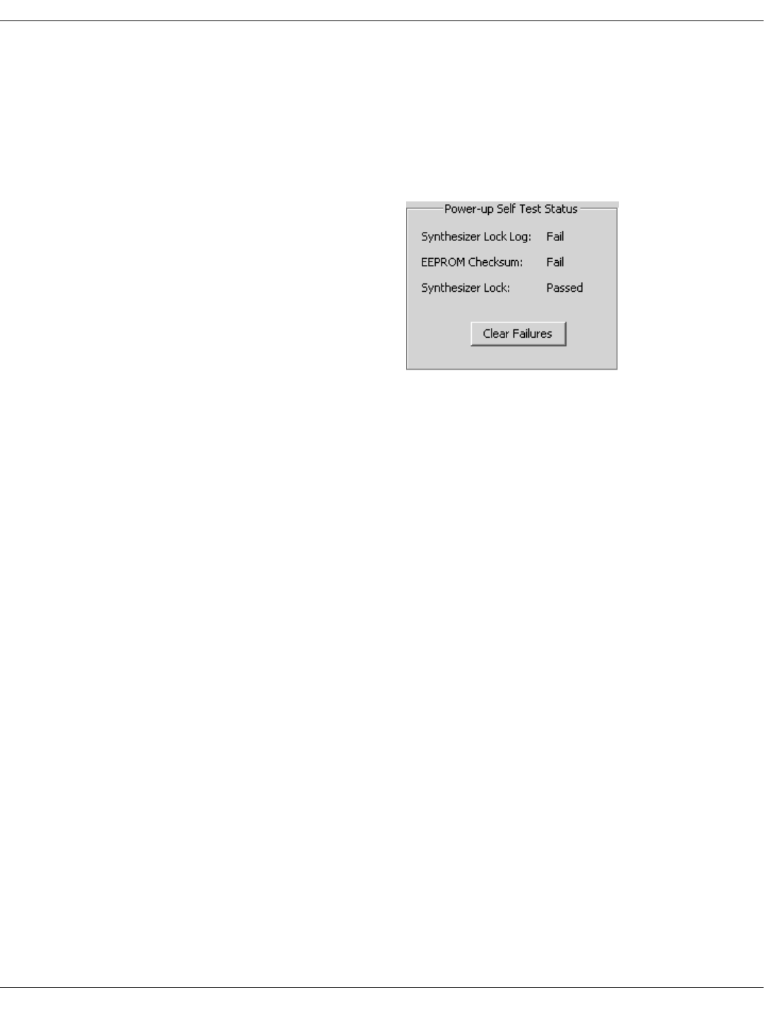
Power-up Self Test Status Power-up self-tests (reference G in “Program ApexPro CH Transmitter
Window” on page 35) run whenever the transmitter is powered up. You can
view the test results with the Apex & ApexPro Tx Config software. The
results shown indicate pass-or-fail status for these power-up self-tests:
Synthesizer Lock Log — Indicates fail status if the transmitter was ever
unable to operate at its programmed frequency. A single failure may be
caused by a temporary deviation. Repeated failures may indicate a
hardware problem. If this is the case, contact Technical Support. (See
“Technical Support” on page 51.)
EEPROM Checksum — Indicates whether the transmitter firmware is
valid or is corrupt.
Synthesizer Lock — Shows the current status of the phase lock loop in
the transmitter. This indicates whether or not the transmitter is
operating at its programmed frequency. Failure of this test indicates that
this transmitter could be operating at a different frequency and could be
causing interference with another transmitter programmed to that other
frequency. If this is the case, this transmitter should be removed from
service until the problem is corrected. Refer to “Power-Up Self-Test
Failures” on page 50.
NOTE
NOTENOTE
NOTE
The Clear Faliures button only displays when in Super User mode. (See
“Access Super User Mode” on page 52.) If any test has failed, access
Super User mode and click the Clear Faliures button. If any tests fail
again, see “Power-Up Self-Test Failures” on page 50.
335A
Draft

40 APEX, ApexPro, and ApexPro CH Transmitter Programming Instructions Revision A - Draft 7
2001989-135
ApexPro CH Transmitter
Diagnostic Test Diagnostic tests (reference D in “Appendix 2: Access ApexPro CH Technical
Functions (Super User)” on page 52) run at all times but are accessible only
by personnel authorized for high-level (Super User) functions.
Battery – the specific combined voltage of the two AA batteries in the
transmitter. Each AA battery is nominally rated at 1.5V, so two fresh
batteries together should register at 3.0V. The lowest total voltage for
the transmitter to operate properly is approximately 1.5V.
Battery Status – the relative strength of the AA batteries in the
transmitter, ranging from zero (dead) to 7 (full power).
Lead Status – the status of any leads connected to the transmitter. Since
the transmitter is connected to the programming device and not to any
leads, the status during the programming process will always be “2F”,
indicating no leads attached.
Button Status – indicates which buttons on the transmitter are being
pressed. You can use this to test the buttons if you suspect they may be
stuck.
0 = All three buttons are pressed.
1 = Attendent Call and Graph buttons are pressed.
2 = Attendent Call and Verify Leads buttons are pressed.
3 = Attendent Call button is pressed.
4 = Graph and Verify Leads buttons are pressed.
5 = Graph button is pressed.
6 = Verify Leads button is pressed.
7 = No buttons are pressed.
330A
Draft
Revision A - Draft 7 APEX, ApexPro, and ApexPro CH Transmitter Programming Instructions 41
2001989-135
ApexPro CH Transmitter
View Firmware Codes
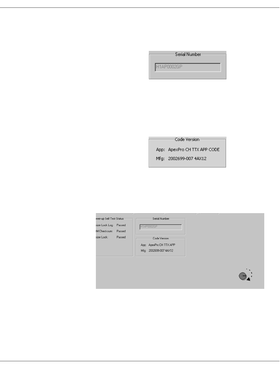
Serial Number Displays the serial number of the transmitters’s PCB (Printed Circuit
Board).
Code Version Numbers Display of the part numbers and their versions (reference I in “Program
ApexPro CH Transmitter Window” on page 35) for the application firmware
(used when the transmitter is operating independently to send patient data),
and the manufacturing firmware (used when the transmitter is plugged into
the programming device).
Communication Status Button The Communication status button (reference J in “Program ApexPro CH
Transmitter Window” on page 35) revolves clockwise to indicate that the
hardware (transmitter, programming device, and the PC) is properly
connected and the software is processing normally.
In addition, by clicking on this button, authorized personnel can access high-
level functions (Super User). A password is needed to access these functions.
See “Appendix 2: Access ApexPro CH Technical Functions (Super User)” on
page 52 for more information.
341A
345A
305A
Draft

42 APEX, ApexPro, and ApexPro CH Transmitter Programming Instructions Revision A - Draft 7
2001989-135
ApexPro CH Transmitter
Update Transmitter Firmware
Update Firmware Code
Occasionally there are updates to the transmitter firmware. In addition, in
rare cases, you may experience problems with the firmware and may need to
download one or more of the files to the transmitter. See “Appendix 1:
ApexPro CH Troubleshooting” on page 49 to determine which file(s), if any,
should be downloaded.
The files to download will have these extensions:
.app (Application firmware code – for transmitter operation)
.mfg (Manufacturing firmware code – for programming the
transmitter)
When updating the transmitter firmware, these files are installed in
C:\Program Files\GE Medical Systems\Apex and ApexPro Programming
Box Software, except if a different location is chosen. When downloading
specific files after experiencing problems, you will find the necessary files on
your hard drive where the firmware was installed.
Firmware Download If the transmitter is functioning:
These conditions will require downloading the Application and Software
code.
RA or LA lights on the transmitter are flashing.
Transmitter is working correctly but the firmware needs to be
updated.
The EEPROM Checksum test failed.
If the transmitter is not functioning:
Manually reset it as instructed in “Reset the Transmitter Manually” on
page 51.
Erase & Download Application Code
1. Access the high-level technical functions of the software as described in
“Access Super User Mode” on page 52.
2. The Program ApexPro CH Transmitter window will display additional
features, including a Download EEPROM Code button (reference E in
“Appendix 2: Access ApexPro CH Technical Functions (Super User)” on
page 52.)
Draft
Revision A - Draft 7 APEX, ApexPro, and ApexPro CH Transmitter Programming Instructions 43
2001989-135
ApexPro CH Transmitter
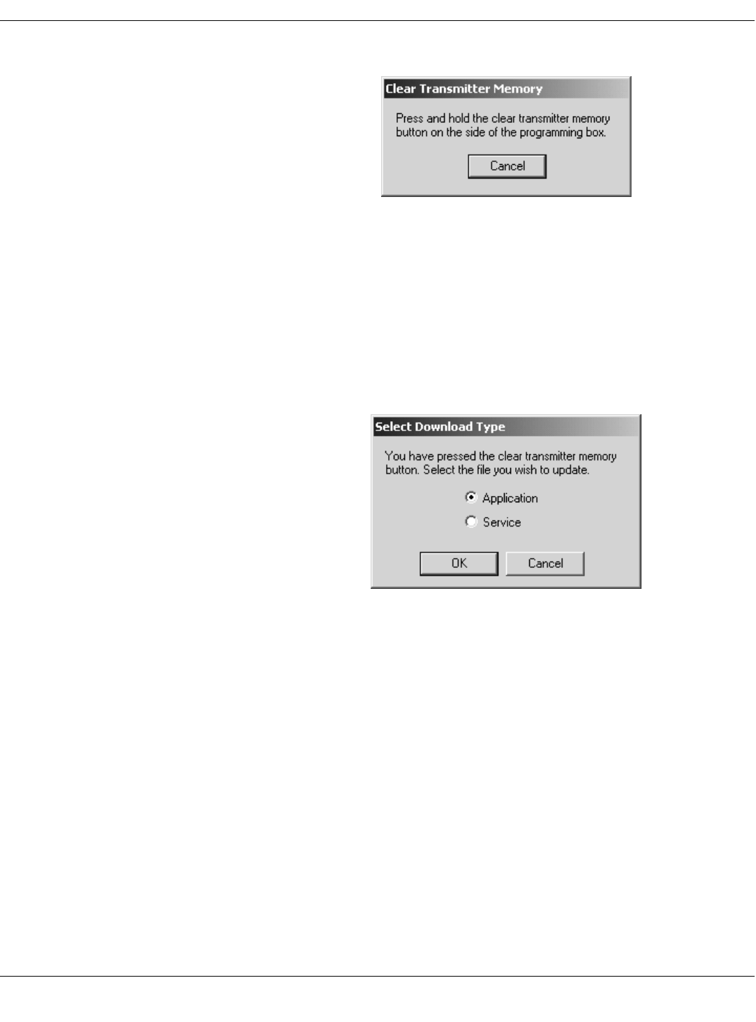
3. Select the Download EEPROM Code button. The message shown below
will display.
NOTE
NOTENOTE
NOTE
If the above message does not display, you must manually reset the
program as instructed in “Reset the Transmitter Manually” on page 51.
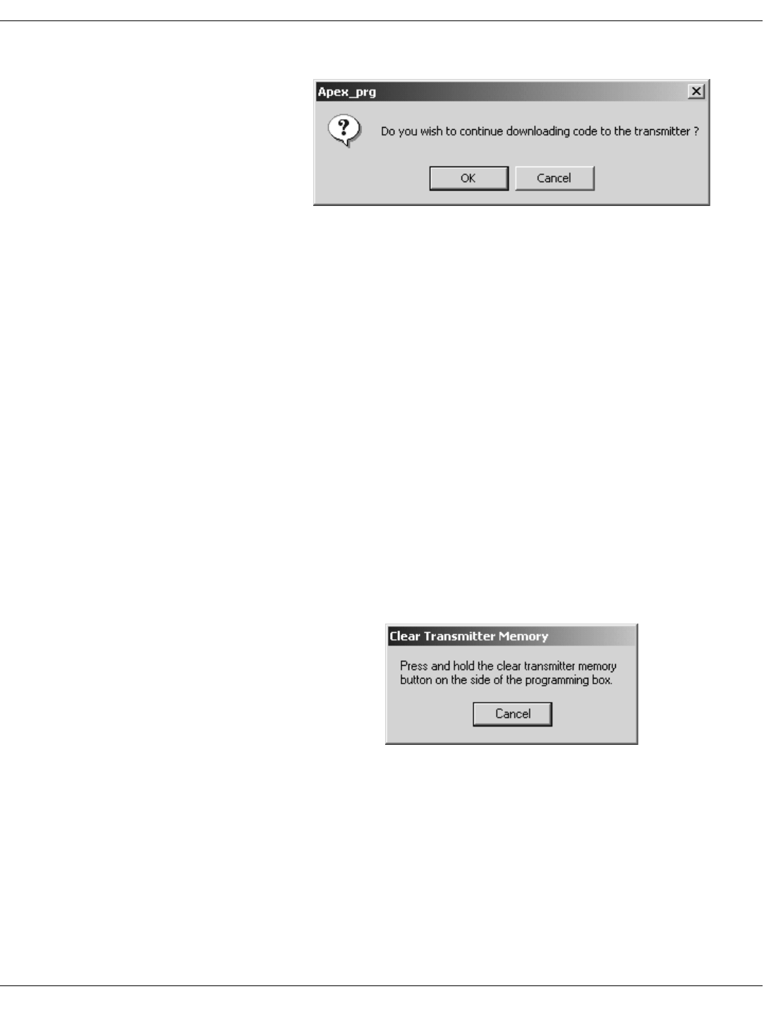
4. Using a small pointed device (such as the tip of a pen) press in and hold
the Clear Transmitter Memory button in the side of the Apex
programming device. Another window will display after approximately 4
seconds. Or select Cancel to stop the download process and return to the
Super User window.
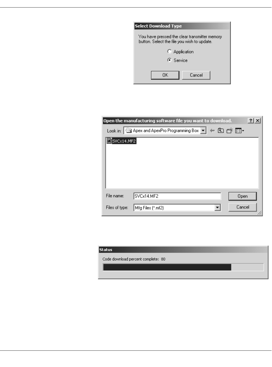
5. Select the type of file to update and select OK.
386A
387A
Draft
44 APEX, ApexPro, and ApexPro CH Transmitter Programming Instructions Revision A - Draft 7
2001989-135
ApexPro CH Transmitter
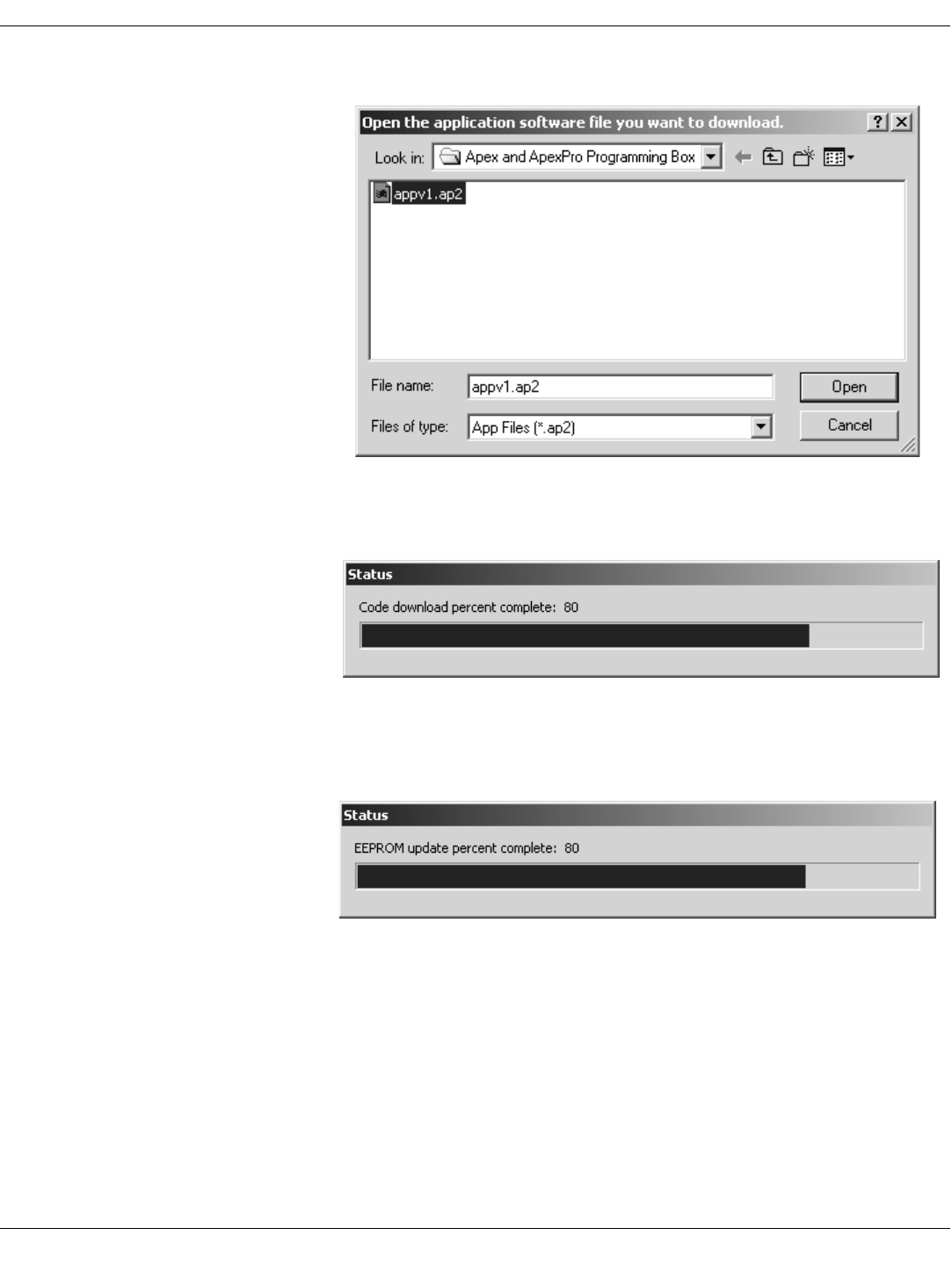
6. Click once on the .app file and select Open. The upgrade process starts
automatically.
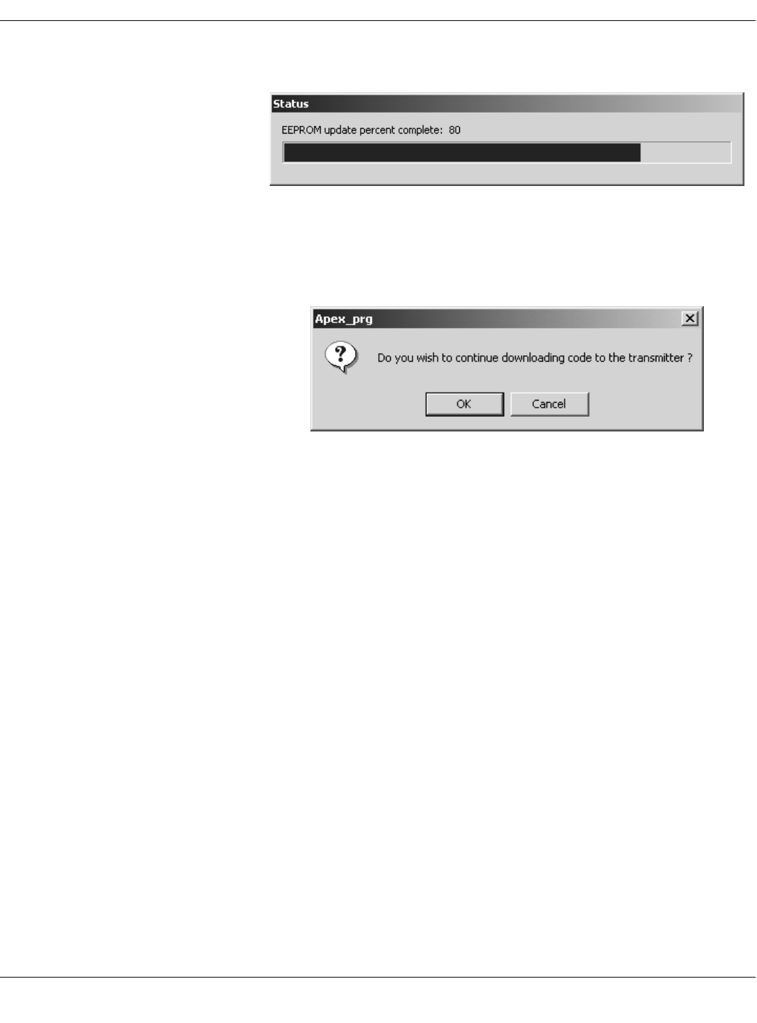
7. A code download status bar displays the progress of the code download.
In addition, the RA LED light on the transmitter flashes.
8. When the code download is complete, a EEPROM update status bar
displays the progress of the EEPROM update. In addition, all the LED
lights on the transmitter flash.
9. A window displays asking if you want to continue downloading code to
the transmitter. (The RA and the LA LED lights flash.) Select OK to
389A
390A
393A
Draft
Revision A - Draft 7 APEX, ApexPro, and ApexPro CH Transmitter Programming Instructions 45
2001989-135
ApexPro CH Transmitter
return to the Select Download Type window, or Cancel to exit the update
process.
To download the Service code, proceed with step 5 in “Erase &
Download Service Code” on page 45
or
Select Cancel to exit the update process and return to the Program
ApexPro CH Transmitter window. (Selecting Cancel closes Super
User functions.
10. Confirm that all Power-up Self Test Status messages indicate Passed. See
“Appendix 1: ApexPro CH Troubleshooting” on page 49 if any failures
occur.
Erase & Download Service Code
1. Access the high-level technical functions of the software as described in
“Access Super User Mode” on page 52.
2. The Program ApexPro CH Transmitter window will display additional
features, including a Download EEPROM Code button (reference E in
“Appendix 2: Access ApexPro CH Technical Functions (Super User)” on
page 52.)
3. Select the Download EEPROM Code button. The message shown below
will display.
NOTE
NOTENOTE
NOTE
If the above message does not display, you must manually reset the
program as instructed in “Reset the Transmitter Manually” on page 51.
4. Using a small pointed device (such as the tip of a pen) press in and hold
the Clear Transmitter Memory button in the side of the Apex
programming device. Another window will display after approximately 4
seconds. Or select Cancel to stop the download process and return to the
Super User window.
391A
386A
Draft
46 APEX, ApexPro, and ApexPro CH Transmitter Programming Instructions Revision A - Draft 7
2001989-135
ApexPro CH Transmitter
5. Select the type of file to update and select OK.
6. Click once on the .mfg file and select Open. The upgrade process starts
automatically.
7. A code download status bar displays the progress of the code download.
In addition, the LA LED light on the transmitter flashes.
388A
392A
390A
Draft
Revision A - Draft 7 APEX, ApexPro, and ApexPro CH Transmitter Programming Instructions 47
2001989-135
ApexPro CH Transmitter
8. When the code download is complete, a EEPROM update status bar
displays the progress of the EEPROM update. In addition, all the LED
lights on the transmitter flash.
9. A window displays next asking if you want to continue downloading code
to the transmitter. (The RA and the LA LED lights flash.) Select OK to
return to the Select Download Type window, or Cancel to exit the update
process.
To download the Application code, proceed with step 5 in “Erase &
Download Application Code” on page 42
or
Select Cancel to exit the update process and return to the Program
ApexPro CH Transmitter window. (Selecting Cancel closes Super
User functions.
10. Confirm that all Power-up Self Test Status messages indicate Passed. See
“Appendix 1: ApexPro CH Troubleshooting” on page 49 if any failures
occur.
393A
391A
Draft

48 APEX, ApexPro, and ApexPro CH Transmitter Programming Instructions Revision A - Draft 7
2001989-135
ApexPro CH Transmitter
Verify Correct Operation
Verify the Transmitter’s Firmware Code Version
The transmitter’s code version displays in the Program ApexPro CH
Transmitter window. Verify that the App: text string matches the .app file
name listed on the data disk. Also verify that the Mfg: text string matches
the .mfg file name listed on the data disk.
Confirm that all Power-up Self Test Status messages indicate Passed. (See
“Power-Up Self-Test Failures” on page 50.) Call Technical Support (page 51)
if any failures occur.
Verify Transmitter Operation Complete the checkout procedures identified in the ApexPro Telemetry
Transmitter Service Manual.
Track the Software Upgrade (Field Engineer Use Only)
For this upgrade, complete the following.
1. Use the MDOC number found on the data disk as the tracking number in
the PROACTIVE REPAIR# window of the Clarify case.
2. Bill travel and labor only as authorized by Marketing - CIC/ApexPro
using the MDOC number as the PO#.
3. Fill out and fax the “Update Installation Verification Form” provided
with this manual. (Please make additional copies as needed.)
345A
Draft

Revision A - Draft 7 APEX, ApexPro, and ApexPro CH Transmitter Programming Instructions 49
2001989-135
ApexPro CH Transmitter
ApexPro CH Appendices
Appendix 1: ApexPro CH Troubleshooting
LED Status Problems
Condition Possible Cause Possible Actions
No lights are blinking. Hardware is not connected
properly. Check the hardware connections as described in “Connect the Hardware” on
page 11.
Software is not installed. Install the Apex & ApexPro Tx Config software as described in “Install
the Programming Device” on page 9.
Software is not running. Start the Apex & ApexPro Tx Config software as described in “Run
the Apex & ApexPro Programming Box Software” on page 13.
Batteries do not have enough
power. Replace the batteries:
1. Disconnect the transmitter from the programming device.
2. Replace the transmitter batteries with two new AA alkaline batteries.
3. Reconnect the transmitter to the programming device.
One or both firmware files are
corrupt. Follow the instructions in “Update Transmitter Firmware” on page 42.
All lights blink rapidly several
times and then slowly two
times.
Normal status when hardware
has just been properly
connected.
No action needed.
All lights blink on and off every
second. Normal status when hardware
is properly connected and the
software is running.
No action needed.
RA and LA LED lights are
blinking. You have chosen to download
an Application or Service file. Follow the instructions in “Update Firmware Code” on page 42.
Transmitter is receiving a
download of application
firmware.
No action needed.
Draft

50 APEX, ApexPro, and ApexPro CH Transmitter Programming Instructions Revision A - Draft 7
2001989-135
ApexPro CH Transmitter
Programming Problems
Power-Up Self-Test Failures
Condition Possible Cause Possible Actions
Unable to display or program
the transmitter settings. Batteries do not have enough
power or are dead. Replace the batteries:
1. Disconnect the transmitter from the programming device.
2. Replace the transmitter batteries.
3. Reconnect the transmitter to the programming device.
Message indicates No
communication from the
transmitter.
Hardware is not connected
properly. Check the hardware connections as described in “Connect the Hardware” on
page 11.
Incorrect COM port was
selected. 1. Exit this window. (Reference F in “Program ApexPro CH Transmitter
Window” on page 35.)
2. Restart Apex & ApexPro Tx Config: In your PC’s Start menu,
select Programs > GE Medical Systems > Apex & ApexPro
Tx Config > Apex & ApexPro Tx Config.
3. In the Select Transmitter window, choose a different COM Port
from what you selected before. Select OK.
4. Repeat steps 1 through 3 until a connection is established and the
message area indicates Connected to the transmitter.
5. If the transmitter still is not working after trying all of the COM ports, refer
to other sections of this appendix.
Condition Possible Cause Possible Actions
Synthesizer Lock Log indicates
fail status. Transmitter has been unable to
operate at programmed
frequency.
May be caused by temporary conditions. Check the “Synthesizer Lock” test
below for current lock conditions.
If the Synthesizer Lock test is currently passing:
1. Clear the Synthesizer Lock Log (“Power-up Self Test Status” on
page 39), under the Super User mode (“Appendix 2: Access ApexPro CH
Technical Functions (Super User)” on page 52.)
2. Remove the transmitter from the programming box, and allow the
transmitter to reboot.
3. Reconnect the transmitter to the programming box.
4. Check the Synthesizer Lock Log status. If the failure occurs again,
contact Technical Support. (See page 51.)
Synthesizer Lock indicates fail
status. The transmitter is currently
unable to operate at its
programmed frequency.
Try programming the transmitter to another frequency. If the failure still
occurs, contact Technical Support. (See page 51.)
EEPROM Checksum indicates
fail status. The transmitter firmware is
incorrect or corrupt. Cycle the power on the transmitter. If the failure still occurs, download new
application and service firmware into the transmitter. (See “Update
Transmitter Firmware” on page 42.)
Draft

Revision A - Draft 7 APEX, ApexPro, and ApexPro CH Transmitter Programming Instructions 51
2001989-135
ApexPro CH Transmitter
Other Problems
Reset the Transmitter Manually You can manually reset the transmitter if:
the Power-up Self-Test Status section of the Program ApexPro CH
Transmitter window shows that the EEPROM Checksum test failed
or
none of the above processes corrects the problem you are experiencing.
NOTE
NOTENOTE
NOTE
You need Super User authority, page 52, to complete this procedure.
To manually reset the transmitter:
1. Complete the procedure “Connect the Hardware” on page 11.
2. Using the tip of a pen or other object with a small point, depress the
Clear Transmitter Memory button on the side of the programming
device and at the same time, turn off the transmitter and turn it back on
by sliding the battery cover away from the battery compartment and
then back. When reset, the RA and LA LEDs will blink.
3. Follow the process “Update Transmitter Firmware” on page 42.
Technical Support If the above information does not resolve your problem, call:
Condition Possible Cause Possible Actions
Unexpected behavior.
Message indicates No
communication from the
transmitter.
Transmitter firmware is corrupt. Manually reset the transmitter and re-load the transmitter firmware. (See
“Reset the Transmitter Manually” below.)
Transmitter is not connected to
the programming device and
the LEDs keep flashing
repeatedly.
The transmitter is resetting:
firmware is probably corrupted. Manually reset the transmitter and re-load the transmitter firmware. (See
“Reset the Transmitter Manually” below.)
U.S. and Canada 800-558-7044
Other countries 561-575-5000
Draft
52 APEX, ApexPro, and ApexPro CH Transmitter Programming Instructions Revision A - Draft 7
2001989-135
ApexPro CH Transmitter
Appendix 2: Access ApexPro CH Technical Functions (Super User)
Several high-level technical functions are available by following the steps in
“Access Super User Mode” below. Technical functions are password-
protected to prevent accidental use. These functions are generally used only
by qualified service personnel.
Requirements You must have the items identified in “Hardware Requirements for the
Programming Device” on page 9.
You may have a software upgrade kit, PN 2007039-005, containing one
software upgrade CD.
Access Super User Mode Start the software as in “Run the Apex & ApexPro Programming Box
Software” on page 13 and then access the Super User mode of the software
by following these steps:
1. Click on the Communication status button (reference C below). A
password prompt will display.
2. Enter the password, mms_aps.
3. Click OK.
365A
Draft
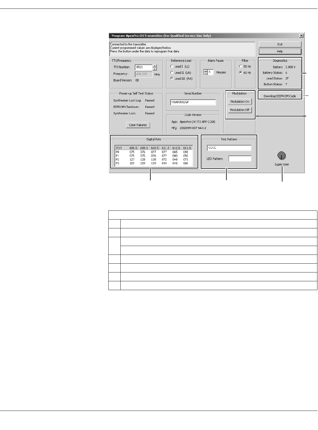
Revision A - Draft 7 APEX, ApexPro, and ApexPro CH Transmitter Programming Instructions 53
2001989-135
ApexPro CH Transmitter
The Program ApexPro CH Transmitter window displays additional Super
User features.
4. To exit Super User mode, click the Communication status button again.
Table 7. Program ApexPro CH Transmitter Technical Functions Window
Ref Definition
AView factory defaults for the Digital Pots
BTest Pattern conducts a Carrier Frequency test
LED Pattern tests whether the LED lights are working correctly
CCommunication status button in Super User mode
DModulation On/Off selection for enabling/disabling modulation
EDownload EEPROM Code for updating the firmware code
FDiagnostic displays self-test results
370A
C
B
A
D
E
F
Draft
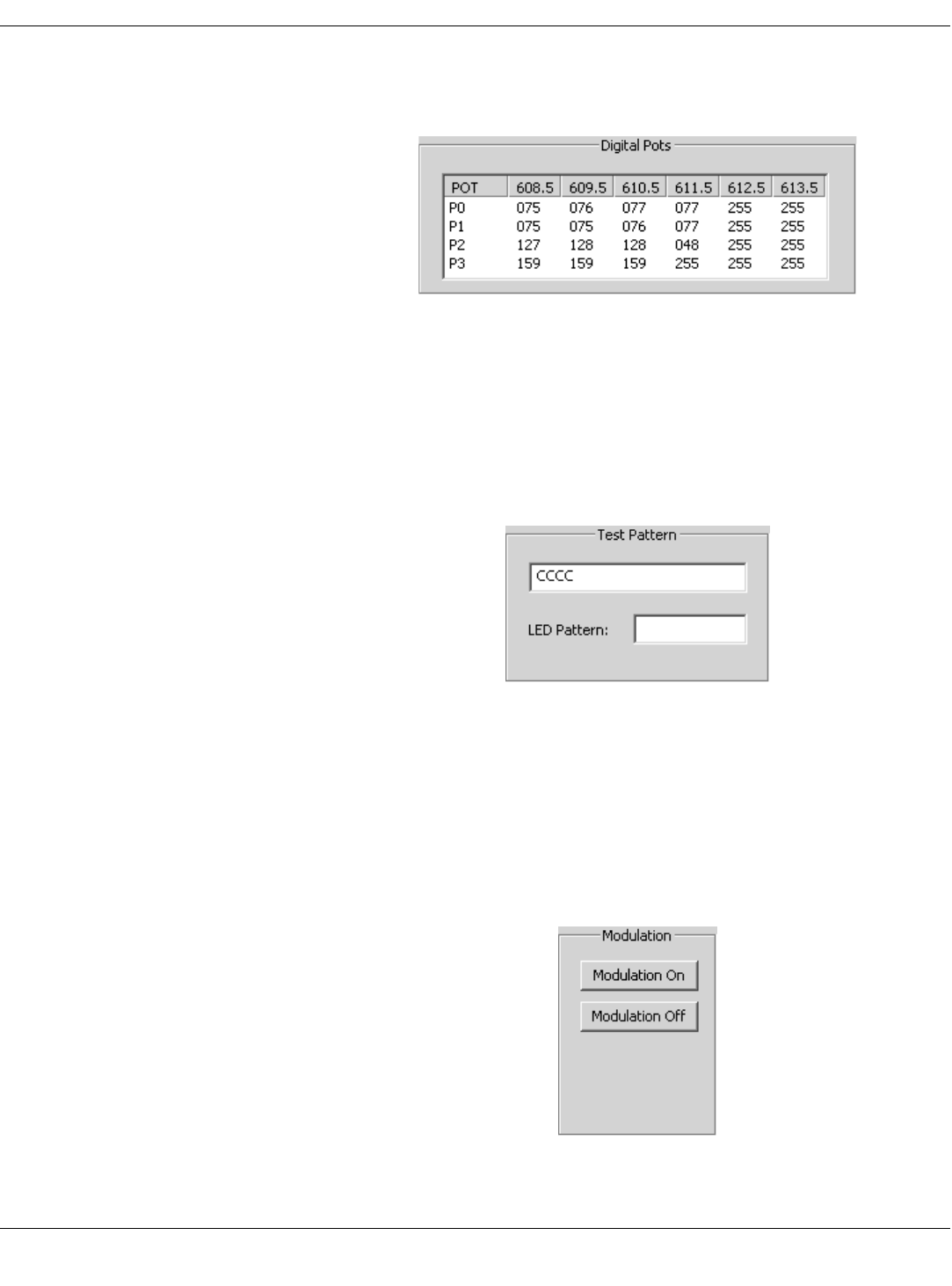
54 APEX, ApexPro, and ApexPro CH Transmitter Programming Instructions Revision A - Draft 7
2001989-135
ApexPro CH Transmitter
Digital Pots
View only. View the factory RF settings. For factory and engineering use
only.
Test Pattern
Test Pattern – a 4-digit hexidecimal value sent by the transmitter to test the
carrier frerquency. See the ApexPro Telemetry Transmitter Service Manual
for detailed information on Carrier Frequency Error test patterns.
LED Pattern – a 2-digit hexidecimal value used to determine if the LED
lights are working.
Modulation
Modulation sets the mode of the frequency being transmitted.
Modulation On – Use during normal operation. Data is transmitted in
relationship to the “peaks” of the high frequencies and the “valleys” of
the low frequencies.
Modulation Off – Use during service routines. Transmitts a constant
frequency with no modulation.
355A
360A
350A
Draft
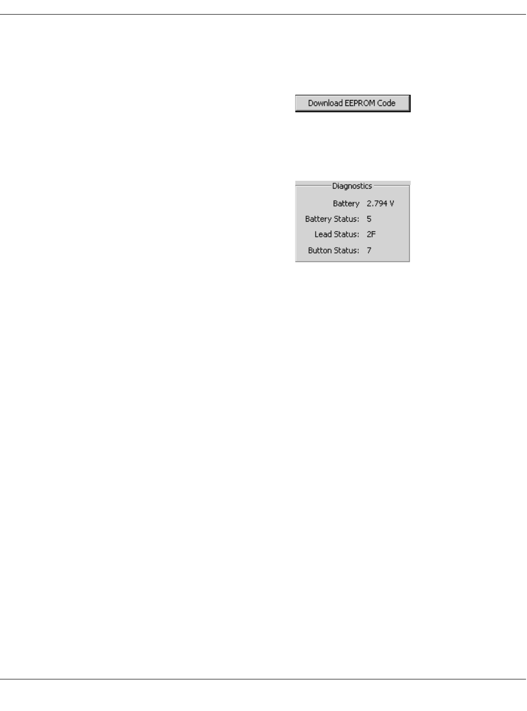
Revision A - Draft 7 APEX, ApexPro, and ApexPro CH Transmitter Programming Instructions 55
2001989-135
ApexPro CH Transmitter
Download EEPROM Code
Click this button to enter download mode. See “Update Firmware Code” on
page 42 for procedure to update the firmware. If the program does not
respond after clicking this button, see “Reset the Transmitter Manually” on
page 51.
Diagnostics
See “Diagnostic Test” on page 40.
375A
330A
Draft
56 APEX, ApexPro, and ApexPro CH Transmitter Programming Instructions Revision A - Draft 7
2001989-135
ApexPro CH Transmitter
Appendix 3: ApexPro CH TTX Labels and Frequencies
Transmitters used with ApexPro CH systems require TTX labels that have
this format:
The available frequency for the ApexPro CH transmitter is:
600 MHz
U.S. TV
Channel Frequency (MHz) TTX# Range ApexPro CH V2 PN Label
37 608.025 - 613.975 8521 - 8759 2009840-009
XXXXAP (XXXX)
TTX
Draft

Revision A - Draft 7 APEX, ApexPro, and ApexPro CH Transmitter Programming Instructions 57
2001989-135
ApexPro Transmitter
4ApexPro Transmitter
Draft

58 APEX, ApexPro, and ApexPro CH Transmitter Programming Instructions Revision A - Draft 7
2001989-135
ApexPro Transmitter
For your notes
Draft
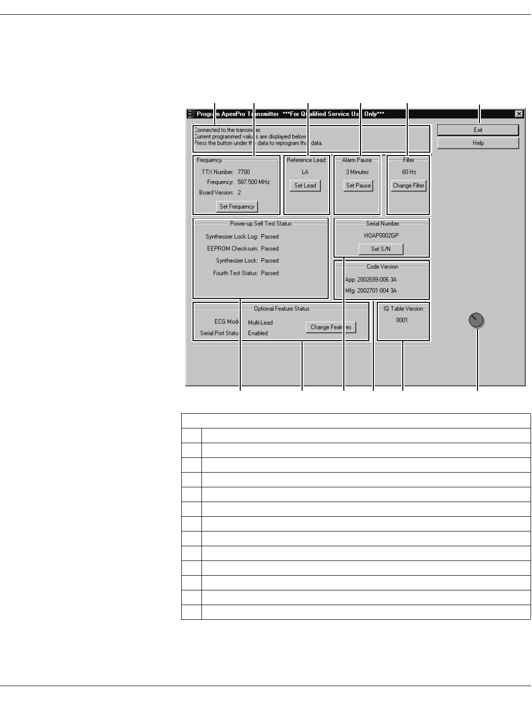
Revision A - Draft 7 APEX, ApexPro, and ApexPro CH Transmitter Programming Instructions 59
2001989-135
ApexPro Transmitter
Program the Transmitter’s Basic Functions
The Main Programming Window
The Program ApexPro Transmitter window displays various configuration
settings for the transmitter. These are described in the sections below.
Table 8. Program ApexPro Transmitter Window
Ref Definition
AMessage area for the programming application
BTTX number and frequency settings
CReference lead setting
DAlarm pause setting
EFilter setting
FExit program button
GPower-up self-test status results
HOptional feature settings
ISerial number of the transmitter
JCode part/version numbers
KIQ table version
LCommunication status button
A F
LKJIHG
B C D E
205A
Draft
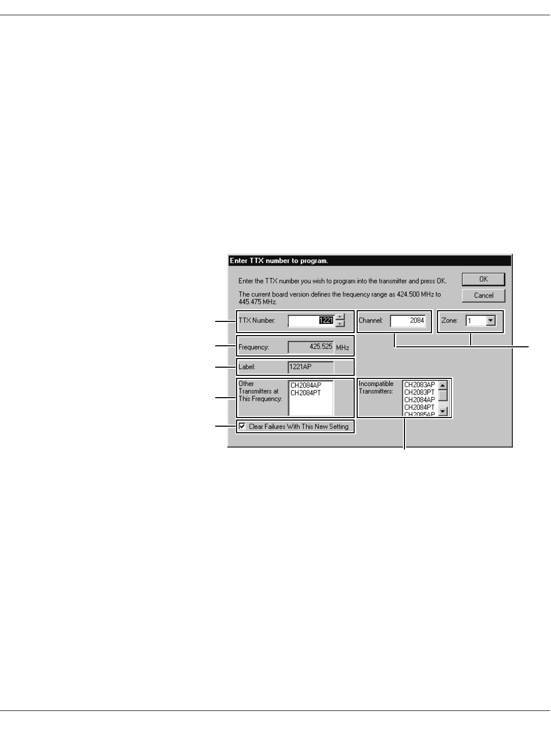
60 APEX, ApexPro, and ApexPro CH Transmitter Programming Instructions Revision A - Draft 7
2001989-135
ApexPro Transmitter
Message Area
This area is used by the software for general status messages, operator
instructions and error messages.
NOTE
NOTENOTE
NOTE
If a message indicates No communication from the transmitter, refer to
“Programming Problems” on page 77.
TTX Number and Frequency Settings
The current TTX number and associated frequency settings are displayed.
The board version, important to a technician, is also displayed.
To change the settings:
1. Select the Set Frequency button, reference B in “Program ApexPro
Transmitter Window” on page 59.
2. Another window appears.
3. This window allows you to:
a – Change the TTX Number: Either use the up- and down-arrows to
scroll to the desired TTX number or highlight and type in the number
to use. The frequency changes automatically as you change the TTX
Number.
b – View the associated Frequency in MHz.
NOTE
NOTENOTE
NOTE
Select a frequency that is within the frequency range allowed by your
location. Operating outside of the allowed frequency range may cause
interference problems or data dropout.
Some frequencies are reserved and cannot be used. If the TTX
number you choose has a reserved frequency, this will be indicated as
RESERVED in the frequency display. See the ApexPro Telemetry
Transmitter Service Manual for a list of TTX numbers, associated
frequencies and reserved frequencies.
a
f
b
c
d
e
210A
g
Draft

Revision A - Draft 7 APEX, ApexPro, and ApexPro CH Transmitter Programming Instructions 61
2001989-135
ApexPro Transmitter
c – View the Label. This is a combination of the TTX number and an
abbreviation of the transmitter model. The label automatically
changes as you change the TTX Number. For example, an ApexPro
transmitter set at TTX number 7700 would be labeled “7700AP”.
d – View Other Transmitters at This Frequency. If there are any
other transmitters set to this frequency, there could be interference
with signals from this transmitter. Avoid this whenever possible.
e – Check the Clear Failures With This New Setting box. This resets
any failed status that was indicated in the Power-up Self-Test Status
section of the Program ApexPro Transmitter window. When this
option is checked, failures will be cleared when you select the OK
button.
f – View Incompatible Transmitters. Incompatible transmitters have
frequencies within +/– 12.5 KHz. These transmitters cannot be
admitted on the same system. If a list of any other transmitters
appears in this box, the TTX number selected cannot be used and the
OK button is disabled. You must select a different TTX Number.
g – Channel and Zone (JAPAN ONLY) are coordinated with TTX
Number in that they change as you change the TTX Number. Refer to
the Apex and ApexPro Transmitter Programming Instructions
(Japan) document for specific usage.
4. Select OK to save your changes or Cancel to revert to the original
settings.
5. Update the “TTX Frequency Chart” in the ApexPro Telemetry
Transmitter Service Manual to identify changes to the TTX numbers and
the frequencies.
6. Select the appropriate TTX label for ApexPro V1, V2 from the label sheet
and apply it to the transmitter inside the label depression located on the
back of the transmitter. (See “Appendix 3: ApexPro TTX Labels and
Frequencies” on page 80 for applicable label part numbers.)
Reference Lead Setting
For 5- or 6-Lead Cables The reference lead setting has no effect when 5- or 6-lead cables are used.
For 5- or 6-lead cables, the reference lead defaults to RL.
For 3-Lead Cables For 3-lead cables, one of the lead wires (LL, LA, or RA) is used to connect the
reference voltage to the patient. Selection of the reference lead determines
which ECG waveform will be displayed at the CIC, according to the table
below.
Select this
reference lead... to view this
waveform at the CIC
Lead I LL (left leg)
Lead II LA (left arm)
Lead III RA (right arm)
Draft
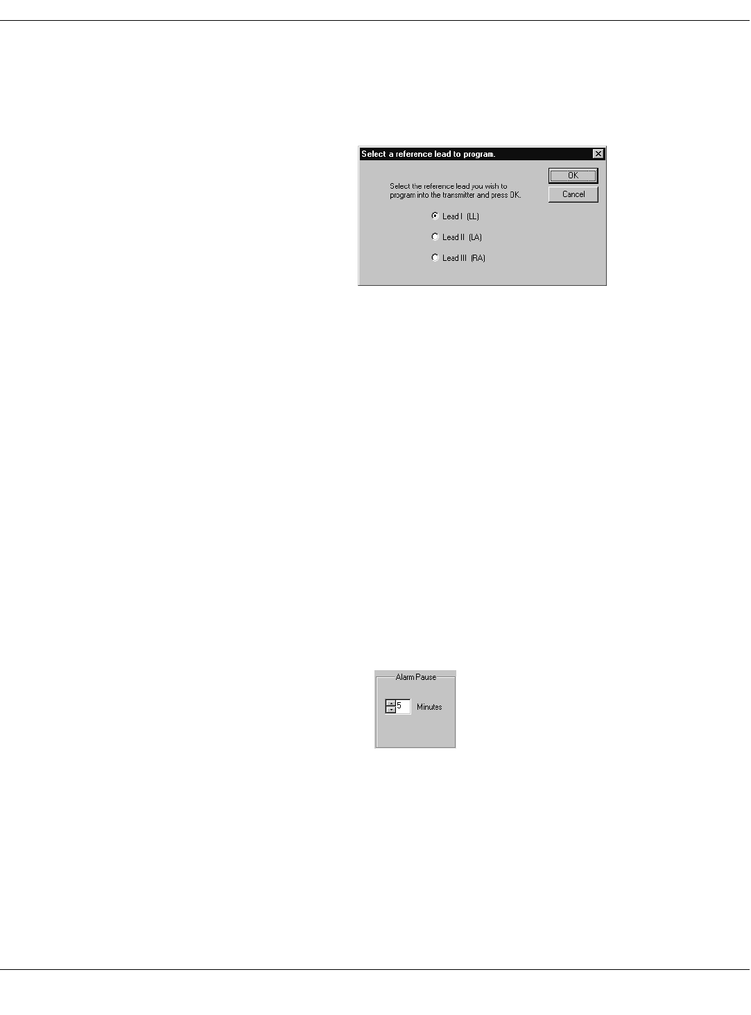
62 APEX, ApexPro, and ApexPro CH Transmitter Programming Instructions Revision A - Draft 7
2001989-135
ApexPro Transmitter
To change the setting:
1. Select the Set Lead button, reference C in “Program ApexPro
Transmitter Window” on page 59.
2. Another window appears. Select the correct lead. (Selecting one
eliminates the others.) Select OK.
3. The change is shown on the Program ApexPro Transmitter window.
Alarm Pause Setting
. The purpose of the alarm pause setting is to allow clinicians to adjust the
transmitter and/or the patient without setting off alarms. The alarm pause
setting is an amount of time, in minutes, during which alarms will not
activate. After this time has elapsed, the alarm pause will automatically be
deactivated and the transmitter will resume normal operation. You can
manually turn off the alarm pause at any time by pressing Verify Leads
and Graph at the same time.
NOTE
NOTENOTE
NOTE
Activation and deactivation of the alarm pause is done on the transmitter
itself. The setting in the software only sets the number of minutes to wait
until the alarm pause times out.
To change the setting:
1. Select the Set Pause button, reference D in “Program ApexPro
Transmitter Window” on page 59.
2. Another window appears.
3. Set the correct number of minutes. Either use the up- and down-arrows
to scroll to the desired number or highlight and type in the number to
use.
4. Select OK.
5. The change is shown on the Program ApexPro Transmitter window.
215A
220A
Draft

Revision A - Draft 7 APEX, ApexPro, and ApexPro CH Transmitter Programming Instructions 63
2001989-135
ApexPro Transmitter
Filter Setting
The filter setting is the frequency of the power lines for the country in which
the transmitter will be used, either 50 or 60 Hz. In the United States, this is
typically 60 Hz. For most other countries, this is typically 50 Hz.
To change the setting:
1. Select the Change Filter button, reference E in “Program ApexPro
Transmitter Window” on page 59.
2. This changes the filter from 60 Hz to 50 Hz or from 50 Hz to 60 Hz.
3. The change is shown on the Program ApexPro Transmitter window.
Exit Button
When you are done with changing all configuration settings, select the Exit
button (reference F in “Program ApexPro Transmitter Window” on page 59)
to save the settings and exit the program.
Draft

64 APEX, ApexPro, and ApexPro CH Transmitter Programming Instructions Revision A - Draft 7
2001989-135
ApexPro Transmitter
View Transmitter Diagnostics
View Firmware Codes
Communication Status Button The Communication status button (reference L in Table 8, “Program
ApexPro Transmitter Window,” on page 59) revolves clockwise to indicate
that the hardware (transmitter, programming device, and the PC) is
properly connected and the software is processing normally.
In addition, by clicking on this button, authorized personnel can access high-
level functions. A password is needed to access these functions. See
“Appendix 2: Access ApexPro Technical Functions” on page 79 for more
information.
Code Version Numbers This is a display of the part numbers and their versions (reference J in
Table 8, “Program ApexPro Transmitter Window,” on page 59) for the
application firmware (used when the transmitter is operating independently
to send patient data) and the manufacturing firmware (used when the
transmitter is plugged into the programming device.)
IQ Table Version This is a display of the version number of the IQ table (reference K in
Table 8, “Program ApexPro Transmitter Window,” on page 59), which is used
for modulation.
View Test Results
Power-up Self-Tests Power-up self-tests (reference G in Table 8, “Program ApexPro Transmitter
Window,” on page 59) run whenever the transmitter is powered up. You can
view the test results with the Apex & ApexPro Tx Config software. The
results shown indicate pass-or-fail status for these power-up self-tests:
Synthesizer Lock Log — Indicates fail status if the transmitter was ever
unable to operate at its programmed frequency. This fail status can be
cleared in the window for TTX number and associated frequency
settings: check the Clear Failures With This New Setting box (Ref. e on
page 60). A single failure may be caused by a temporary deviation.
Repeated failures may indicate a hardware problem. If this is the case,
contact Technical Support. (See “Technical Support” on page 78.)
EEPROM Checksum — Indicates whether the transmitter firmware is
valid or is corrupt.
Synthesizer Lock — Shows the current status of the phase lock loop in
the transmitter. This indicates whether or not the transmitter is
operating at its programmed frequency. Failure of this test indicates that
this transmitter could be operating at a different frequency and could be
causing interference with another transmitter programmed to that other
frequency. If this is the case, this transmitter should be removed from
service until the problem is corrected. Refer to “Power-Up Self-Test
Failures” on page 77.
Fourth Test Status — Reserved for future use.
Draft

Revision A - Draft 7 APEX, ApexPro, and ApexPro CH Transmitter Programming Instructions 65
2001989-135
ApexPro Transmitter
If any test has failed:
1. Select the Set Frequency button, reference B in “Program ApexPro
Transmitter Window” on page 59.
2. Check the Clear Failures With This New Setting box.
If any tests fail again, see “Power-Up Self-Test Failures” on page 77.
Diagnostic Tests Diagnostic tests (reference D in “Appendix 2: Access ApexPro Technical
Functions” on page 79) run at all times but are accessible only by personnel
authorized for high-level functions. The results shown are:
Battery voltage – the specific combined voltage of the two AA batteries in
the transmitter. Each AA battery is nominally rated at 1.5V, so two fresh
batteries together should register at 3.0V. The lowest total voltage for
the transmitter to operate properly is approximately 1.5V.
Battery Status – the relative strength of the AA batteries in the
transmitter, ranging from zero (dead) to 7 (full power).
Lead Status – the status of any leads connected to the transmitter. Since
the transmitter is connected to the programming device and not to any
leads, the status during the programming process will always be “3F”,
indicating no leads attached.
Button status – indicates which buttons on the transmitter are being
pressed. You can use this to test the buttons if you suspect they may be
stuck.
0 = Both Verify Leads and Graph buttons are pressed.
1 = Verify Leads button is pressed.
2 = Graph button is pressed.
3 = Neither button is pressed.
Draft

66 APEX, ApexPro, and ApexPro CH Transmitter Programming Instructions Revision A - Draft 7
2001989-135
ApexPro Transmitter
Update Transmitter Firmware
Update Firmware Code
Occasionally there are updates to the transmitter firmware. In addition, in
rare cases, you may experience problems with the firmware and may need to
download one or more of the files to the transmitter. See “Appendix 1:
ApexPro Troubleshooting” on page 76 to determine which file, if any, should
be downloaded.
The files that may be involved have these extensions:
.app (Application firmware code – for transmitter operation)
.mfg (Manufacturing firmware code – for programming the
transmitter)
.tbl (IQ table – for modulation)
When updating the transmitter firmware, these files are installed in
C:\Program Files\GE Medical Systems\Apex and ApexPro Programming
Box Software, except if a different location is chosen. When downloading
specific files after experiencing problems, you will find the necessary files on
your hard drive where the firmware was installed.
Firmware Download Decisions Follow these instructions if the transmitter is functioning.
If the transmitter is not functioning at all, try manually resetting it as
instructed in “Reset the Transmitter Manually” on page 78.
Erase & Download Application Code
1. Access the high-level technical functions of the software as described in
“Access the Super User Mode” on page 79.
2. The Program ApexPro Transmitter window will display additional
features, including a Download Functions section (reference D in
“Appendix 2: Access ApexPro Technical Functions” on page 79.)
3. Select the Erase & Download App button.
When these conditions occur... Use this Download Function
RA light on the transmitter is flashing. Erase & Download App (page 66)
LA light on the transmitter is flashing. Erase & Download Mfg (page 67)
Transmitter is working correctly but the firmware
needs to be updated. Erase & Download App & Mfg
(page 68)The EEPROM checksum test failed.
The transmitter was manually reset.
There is a problem with the transmitter but you
don’t know what it is. Download File (page 70)
Draft
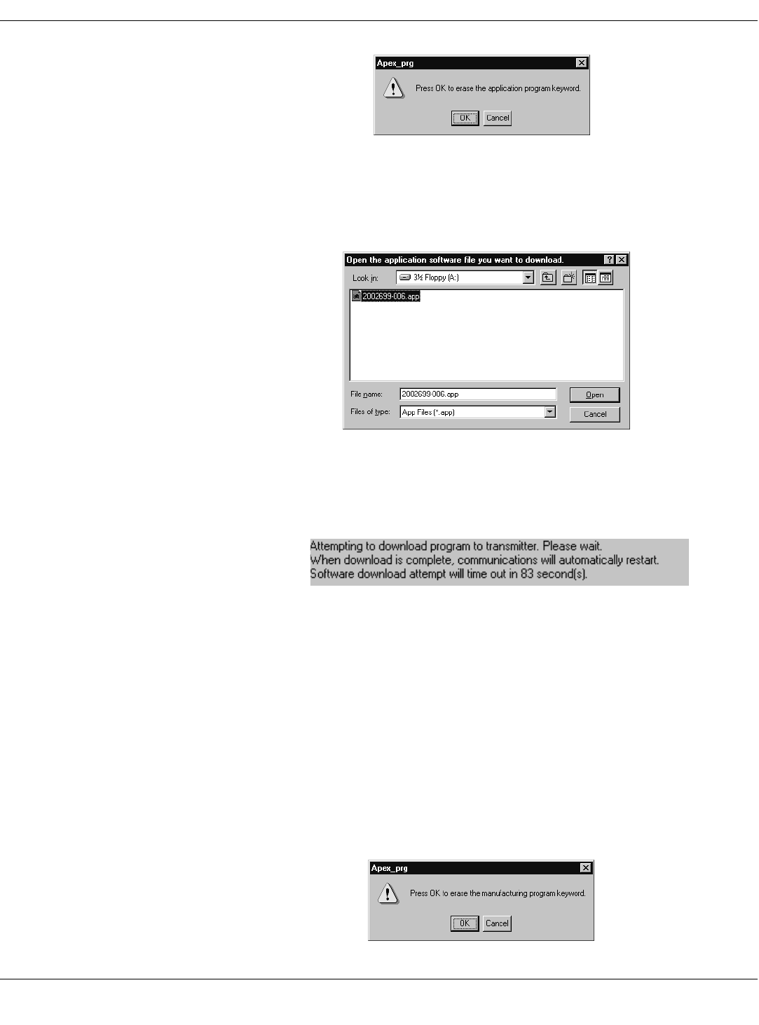
Revision A - Draft 7 APEX, ApexPro, and ApexPro CH Transmitter Programming Instructions 67
2001989-135
ApexPro Transmitter
4. Select OK at this screen.
5. Locate the transmitter firmware, generally in C:\Program Files\GE
Medical Systems\Apex and ApexPro Programming Box Software, or
where the firmware was installed.
6. Click once on the .app file and select Open. The upgrade process starts
automatically.
7. During the upgrade, the message box on the Program ApexPro
Transmitter window displays a countdown timer and the transmitter
settings appear greyed out. In addition, sometimes the RA LED light on
the transmitter flashes and sometimes all the LED lights flash.
8. Wait until the first line in the message box displays the text Connected to
the transmitter. If there are any problems, refer to “ApexPro Appendices”
on page 76.
Erase & Download Service Code
1. Access the high-level technical functions of the software as described in
“Access the Super User Mode” on page 79.
2. The Program ApexPro Transmitter window will display additional
features, including a Download Functions section (reference D in
“Appendix 2: Access ApexPro Technical Functions” on page 79.)
3. Select the Erase & Download Mfg button.
4. Select OK at this screen.
405A
410A
415A
420A
Draft
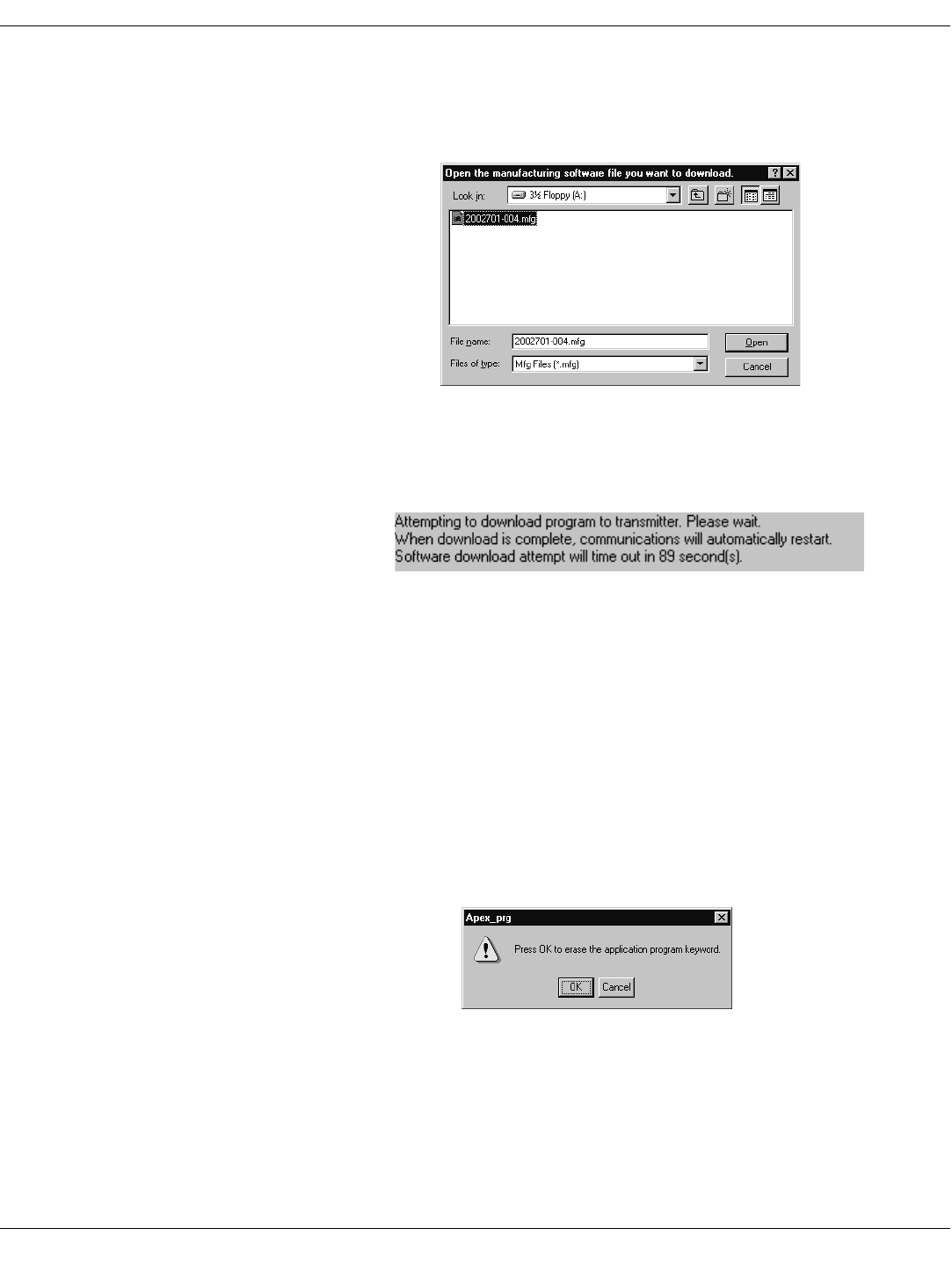
68 APEX, ApexPro, and ApexPro CH Transmitter Programming Instructions Revision A - Draft 7
2001989-135
ApexPro Transmitter
5. Locate the transmitter firmware, generally in C:\Program Files\GE
Medical Systems\Apex and ApexPro Programming Box Software, or
where the firmware was installed.
6. Click once on the .mfg file and select Open. The upgrade process starts
automatically.
7. During the upgrade, the message box on the Program ApexPro
Transmitter window displays a countdown timer and the transmitter
settings appear greyed out. In addition, sometimes the LA LED light on
the transmitter flashes and sometimes all the LED lights flash.
8. Wait until the first line in the message box displays the text Connected to
the transmitter. If there are any problems, refer to “ApexPro Appendices”
on page 76.
Erase & Download Application and Service Codes
1. Access the high-level technical functions of the software as described in
“Access the Super User Mode” on page 79.
2. The Program ApexPro Transmitter window will display additional
features, including a Download Functions section (reference D in
“Appendix 2: Access ApexPro Technical Functions” on page 79.)
3. Select the Erase & Download App & Mfg button.
4. Select OK at this screen.
5. Locate the transmitter firmware, generally in C:\Program Files\GE
Medical Systems\Apex and ApexPro Programming Box Software, or
where the firmware was installed.
425A
430A
405A
Draft
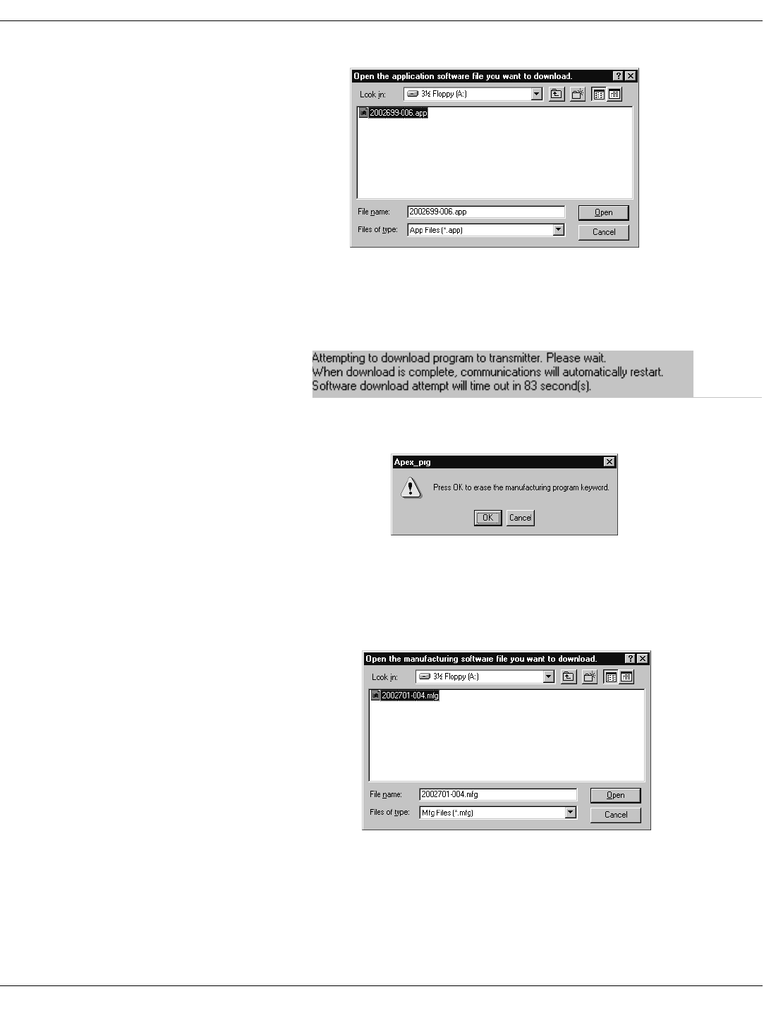
Revision A - Draft 7 APEX, ApexPro, and ApexPro CH Transmitter Programming Instructions 69
2001989-135
ApexPro Transmitter
6. Click once on the .app file and select Open. The upgrade process starts
automatically.
7. During the upgrade, the message box on the Program ApexPro
Transmitter window displays a countdown timer and the transmitter
settings appear greyed out. In addition, sometimes the RA LED light on
the transmitter flashes and sometimes all the LED lights flash.
8. Next, the download process downloads the .mfg file. Select OK at this
screen.
9. Locate the transmitter firmware, generally in C:\Program Files\GE
Medical Systems\Apex and ApexPro Programming Box Software, or
where the firmware was installed.
10. Click once on the .mfg file and select Open. The upgrade process starts
automatically.
11. During the upgrade, the message box on the Program ApexPro
Transmitter window displays a countdown timer and the transmitter
410A
415A
420A
425A
Draft
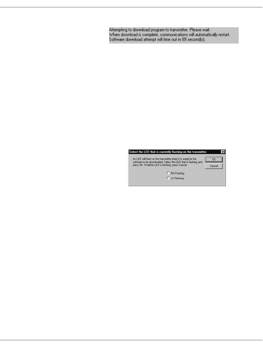
70 APEX, ApexPro, and ApexPro CH Transmitter Programming Instructions Revision A - Draft 7
2001989-135
ApexPro Transmitter
settings appear greyed out. In addition, sometimes the LA LED light on
the transmitter flashes and sometimes all the LED lights flash.
12. Wait until the first line in the message box displays the text Connected to
the transmitter. If there are any problems, refer to “ApexPro Appendices”
on page 76.
Download File This function helps determine which firmware file to download, either the
application code or the manufacturing code.
1. Access the high-level technical functions of the software as described in
“Access the Super User Mode” on page 79.
2. The Program ApexPro Transmitter window will display additional
features, including a Download Functions section (reference D in
“Appendix 2: Access ApexPro Technical Functions” on page 79.)
3. Select the Download File button.
4. Follow the instructions at this screen.
If the RA light is flashing, select RA Flashing and then select OK.
If the LA light is flashing, select LA Flashing and then select OK.
If neither LED is flashing on the transmitter, there is no need to
update the firmware, so you can select Cancel.
Change the IQ Table Version The IQ table is used to generate the RF modulation in the transmitter.
If you receive a new IQ table file:
1. Access the high-level technical functions of the software as described in
“Access the Super User Mode” on page 79.
2. Select the Load I/Q Table button, reference B in “Appendix 2: Access
ApexPro Technical Functions” on page 79.
430A
440A
Draft
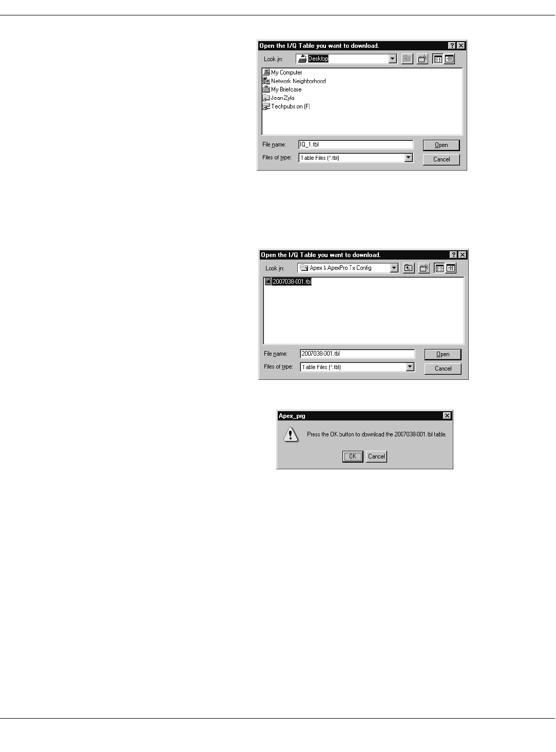
Revision A - Draft 7 APEX, ApexPro, and ApexPro CH Transmitter Programming Instructions 71
2001989-135
ApexPro Transmitter
3. A window opens for you to navigate to the I/Q Table you need.
4. Locate the transmitter firmware, generally in C:\Program Files\GE
Medical Systems\Apex and ApexPro Programming Box Software, or
where the firmware was installed.
5. Click once on the .tbl file and select Open.
6. Select OK.
7. The transmitter’s settings will disappear temporarily from the Program
ApexPro Transmitter window. When the settings reappear, verify that
the I/Q Table Version matches the last three digits of the .tbl file name
listed on the CD.
NOTE
NOTENOTE
NOTE
The version has 4 digits and is stored inside the table itself. The version
number may not correlate to the file name or to the firmware part
number.
8. Confirm that all Power-up Self Test Status messages indicate Passed. See
“Appendix 1: ApexPro Troubleshooting” on page 76 if any failures occur.
445A
450A
455A
Draft
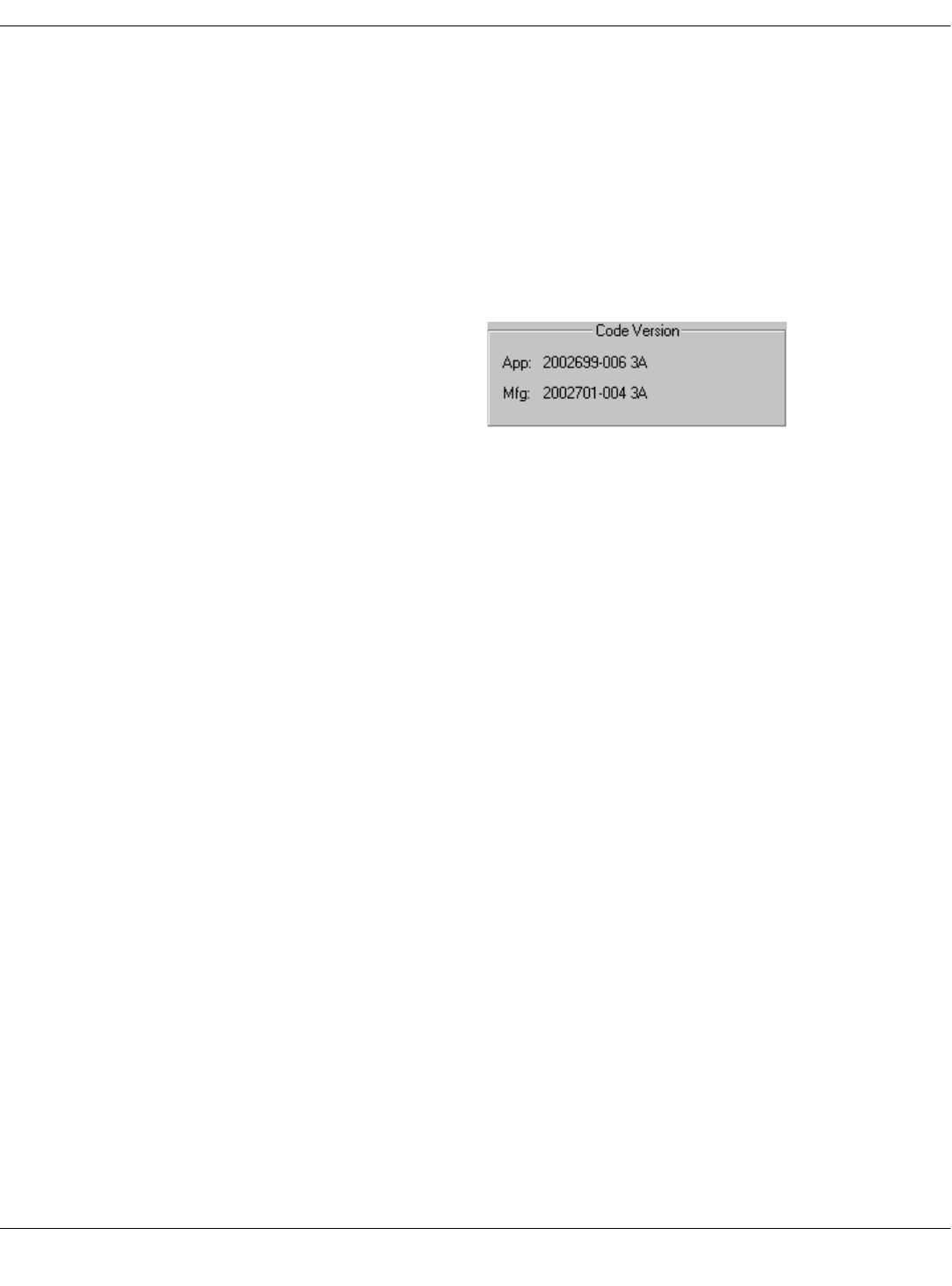
72 APEX, ApexPro, and ApexPro CH Transmitter Programming Instructions Revision A - Draft 7
2001989-135
ApexPro Transmitter
Verify Correct Operation
Verify the Transmitter’s Firmware Versions
1. Disconnect the transmitter from the programming device and wait for
the transmitter to reboot. (All the LED lights flash rapidly several times
and then slowly two times.)
2. Reconnect the transmitter to the programming device.
3. When the transmitter’s settings reappear in the Program ApexPro
Transmitter window, verify that the Code Version App: text string
matches the .app file name listed on the data disk. Also verify that the
Code Version Mfg: text string matches the .mfg file name listed.
4. Confirm that all Power-up Self Test Status messages indicate Passed.
Call Technical Support (page 78) if any failures occur.
Verify Transmitter Operation Complete the checkout procedures identified in the ApexPro Telemetry
Transmitter Service Manual.
Track the Software Upgrade (Field Engineer Use Only)
For this upgrade, complete the following.
1. Use the MDOC number found on the data disk as the tracking number in
the PROACTIVE REPAIR# window of the Clarify case.
2. Bill travel and labor only as authorized by Marketing - CIC/ApexPro
using the MDOC number as the PO#.
3. Fill out and fax the “Update Installation Verification Form” provided
with this manual. (Please make additional copies as needed.)
460A
Draft

Revision A - Draft 7 APEX, ApexPro, and ApexPro CH Transmitter Programming Instructions 73
2001989-135
ApexPro Transmitter
Perform Advanced Functions
Set Transmitter Feature Level
Three settings are available, with varying levels of software functions. Using
a password obtained from the packing slip, you can enable these functions.
Feature Levels
Requirements for Setting Features
1. Verify the transmitter firmware is at version 2A or later.
2. Verify you have the packing slip identifying the software feature
password. The password is specific to each transmitter’s serial number.
(To get the password, contact Technical Support. See page 78.)
3. Verify you have the items identified in the “Hardware Requirements for
the Programming Device” on page 9.
4. Verify the transmitter programming software is at version 2A or later:
Under your PC’s Start menu, select Programs > Apex & ApexPro Tx
Config > Readme.txt to identify the configuration software version,
shown in the headings.
Procedure for Setting Features
1. Complete the procedure “Install the Programming Device” on page 9.
2. Complete the procedure “Connect the Hardware” on page 11.
3. Run the programming software. (See “Run the Apex & ApexPro
Programming Box Software” on page 13.)
4. Access the high-level technical functions of the software as described in
“Access the Super User Mode” on page 79.
5. Confirm the features available in the Optional Feature Status field,
reference A in “Appendix 2: Access ApexPro Technical Functions” on
page 79.
6. To enable a feature, complete the following steps:
Feature Level Functionality
Multi-Lead ECG acquisition with
fully-functional interface
connector ports
The transmitter can be used with
multiple leads and can be used with
accessories that use the serial ports.
This is the typical level.
Single Lead ECG acquisition with
fully-functional interface
connector ports
The transmitter can only be used for
single-lead acquisition but can be
used with a number of accessories,
including the programming device.
Single Lead ECG acquisition with
service-use only interface
connector ports
The transmitter can only be used
with a single lead and can not be
used with any accessories except the
programming device.
Draft
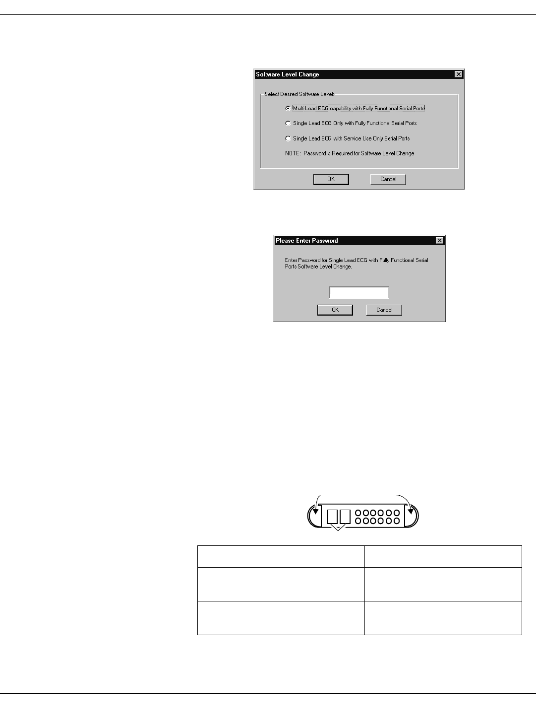
74 APEX, ApexPro, and ApexPro CH Transmitter Programming Instructions Revision A - Draft 7
2001989-135
ApexPro Transmitter
a. Select the Change Features button.
b. Click on the desired software level, then select OK. Note that if you
downgrade, you will lose some features.
c. Enter the password. (To get the password, contact Technical
Support. See page 78.) Then select OK.
7. The change is shown on the Program ApexPro Transmitter window.
Check the Optional Feature Status field to verify that the features you
selected were enabled.
Verify Transmitter Operation Complete the checkout procedures identified in the ApexPro Telemetry
Transmitter Service Manual.
Update Labels and Dust Covers The screw cover labels and the dust covers are used to visually identify the
software features of the transmitter. If the feature level is changed, the
labels and the dust covers should be updated according to the table below.
520A
530A
Feature Transmitter Appearance
Multi-Lead ECG acquisition with fully-
functional interface connector ports Grey-colored screw cover label
Grey-colored dust covers
Single Lead ECG acquisition with fully-
functional interface connector ports Single Lead screw cover label
Grey-colored dust covers
Dust covers
Screw cover labels
Draft

Revision A - Draft 7 APEX, ApexPro, and ApexPro CH Transmitter Programming Instructions 75
2001989-135
ApexPro Transmitter
Track the Software Upgrade (Field Engineer Use Only)
For this upgrade, complete the following:
1. Use the appropriate MDOC number in the table below as the tracking
number in the PROACTIVE REPAIR# window of the Clarify case.
2. Bill travel and labor only as authorized by Marketing - CIC/ApexPro
using the MDOC number as the PO#.
3. Fill out and fax the “Update Installation Verification Form” provided
with this manual. (Please make additional copies as needed.)
Single Lead ECG acquisition with service-
use only interface connector ports Blue-colored dust covers
Screw cover label:
Feature Transmitter Appearance
535A
Number Software Feature
MDOC-640 APROT1-APROT1P UPGD APROTX UPG
1-ECG ONLY TO SERIAL PORT
MDOC-641 APROT1-APROTX UPGD APROTX UPG
1-ECG TO MULTILEAD + PORT
APROT1P-APROTX UPGD APROTX UPG
1-ECG W/ PORT TO MULTI + PORT
Draft

76 APEX, ApexPro, and ApexPro CH Transmitter Programming Instructions Revision A - Draft 7
2001989-135
ApexPro Transmitter
ApexPro Appendices
Appendix 1: ApexPro Troubleshooting
LED Status Problems
Condition Possible Cause Possible Actions
No lights are blinking. Hardware is not connected
properly. Check the hardware connections as described in “Connect the Hardware” on
page 11.
Software is not installed. Install the Apex & ApexPro Tx Config software as described in “Install
the Programming Device” on page 9.
Software is not running. Start the Apex & ApexPro Tx Config software as described in “Run
the Apex & ApexPro Programming Box Software” on page 13.
Batteries do not have enough
power. Replace the batteries:
1. Disconnect the transmitter from the programming device.
2. Replace the transmitter batteries with two new AA alkaline batteries.
3. Reconnect the transmitter to the programming device.
One or both firmware files are
corrupt. Follow the instructions in “Download File” on page 70.
All lights blink rapidly several
times and then slowly two
times.
Normal status when hardware
has just been properly
connected.
No action needed.
All lights blink on and off every
second. Normal status when hardware
is properly connected and the
software is running.
No action needed.
RA LED light is blinking. You have chosen to “Download
File” as on page 70 and need
to download the .app file.
Follow the instructions in “Erase & Download Application Code” on page 66.
Transmitter is receiving a
download of application
firmware.
No action needed.
LA LED light is blinking. You have chosen to “Download
File” as on page 70 and need
to download the .mfg file.
Follow the instructions in “Erase & Download Service Code” on page 67.
Transmitter is receiving a
download of service firmware. No action needed.
Draft

Revision A - Draft 7 APEX, ApexPro, and ApexPro CH Transmitter Programming Instructions 77
2001989-135
ApexPro Transmitter
Programming Problems
Power-Up Self-Test Failures
Condition Possible Cause Possible Actions
Unable to display or program
the transmitter settings. Batteries do not have enough
power or are dead. Replace the batteries:
1. Disconnect the transmitter from the programming device.
2. Replace the transmitter batteries.
3. Reconnect the transmitter to the programming device.
Message indicates No
communication from the
transmitter.
Hardware is not connected
properly. Check the hardware connections as described in “Connect the Hardware” on
page 11.
Incorrect COM port was
selected. 1. Exit this window. (Reference F in “Program ApexPro Transmitter
Window” on page 59.)
2. Restart Apex & ApexPro Tx Config: In your PC’s Start menu,
select Programs > GE Medical Systems > Apex & ApexPro
Tx Config > Apex & ApexPro Tx Config.
3. In the Select Transmitter window, choose a different COM Port
from what you selected before. Select OK.
4. Repeat steps 1 through 3 until a connection is established and the
message area indicates Connected to the transmitter.
5. If the transmitter still is not working after trying all of the COM ports, refer
to other sections of this appendix.
Condition Possible Cause Possible Actions
Synthesizer Lock Log indicates
fail status. Transmitter has been unable to
operate at programmed
frequency.
May be caused by temporary conditions. Check the “Synthesizer Lock” test
below for current lock conditions.
If the Synthesizer Lock test is currently passing:
1. Clear the Synthesizer Lock Log (“Power-up Self-Tests” on page 64),
under the Super User mode (“Appendix 2: Access ApexPro Technical
Functions” on page 79.)
2. Remove the transmitter from the programming box, and allow the
transmitter to reboot.
3. Reconnect the transmitter to the programming box.
4. Check the Synthesizer Lock Log status. If the failure occurs again,
contact Technical Support. (See page 78.)
Synthesizer Lock indicates fail
status. The transmitter is currently
unable to operate at its
programmed frequency.
Try programming the transmitter to another frequency. If the failure still
occurs, contact Technical Support. (See page 78.)
EEPROM Checksum indicates
fail status. The transmitter firmware is
incorrect or corrupt. Cycle the power on the transmitter. If the failure still occurs, download new
application and service firmware into the transmitter. (See “Erase &
Download Application and Service Codes” on page 68.)
Draft

78 APEX, ApexPro, and ApexPro CH Transmitter Programming Instructions Revision A - Draft 7
2001989-135
ApexPro Transmitter
Other Problems
Reset the Transmitter Manually You can manually reset the transmitter, if:
the Power-up Self-Test Status section of the Program ApexPro
Transmitter window shows that the EEPROM Checksum test failed
or
none of the above processes corrects the problem you are experiencing.
NOTE
NOTENOTE
NOTE
You need Super User authority, page 79, to complete this procedure.
To manually reset the transmitter:
1. Complete the procedure “Connect the Hardware” on page 11.
2. Using the tip of a pen or other object with a small point, depress the
Clear Transmitter Memory button on the side of the programming
device and at the same time, turn off the transmitter and turn it back on
by sliding the battery cover away from the battery compartment and
then back. When reset, the RA LED will blink.
3. Follow the process “Erase & Download Application and Service Codes” on
page 68.
Technical Support If the above information does not resolve your problem, call:
Condition Possible Cause Possible Actions
Unexpected behavior.
Message indicates No
communication from the
transmitter.
Transmitter firmware is corrupt. Manually reset the transmitter and re-load the transmitter firmware. (See
“Reset the Transmitter Manually” below.)
Transmitter is not connected to
the programming device and
the LEDs keep flashing
repeatedly.
The transmitter is resetting:
firmware is probably corrupted. Manually reset the transmitter and re-load the transmitter firmware. (See
“Reset the Transmitter Manually” below.)
U.S. and Canada 800-558-7044
Other countries 561-575-5000
Draft
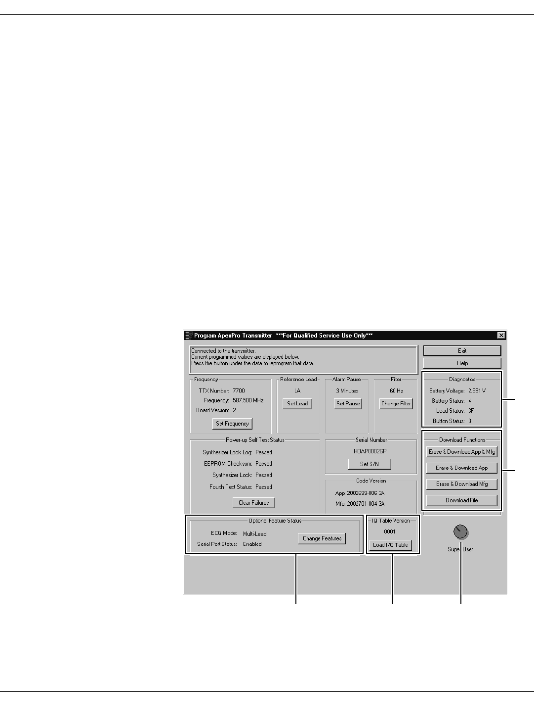
Revision A - Draft 7 APEX, ApexPro, and ApexPro CH Transmitter Programming Instructions 79
2001989-135
ApexPro Transmitter
Appendix 2: Access ApexPro Technical Functions
Several high-level technical functions are available by following the steps in
“Access the Super User Mode” below. Technical functions are password-
protected to prevent accidental use.
Requirements You must have the items identified in “Hardware Requirements for the
Programming Device” on page 9.
You may have a software upgrade kit, PN 2007039-005, containing one
software upgrade CD.
Access the Super User Mode Start the software as in “Run the Apex & ApexPro Programming Box
Software” on page 13 and then access the Super User mode of the software
by following these steps:
1. Select the Communication status button, reference L in “Program
ApexPro Transmitter Window” on page 59 and reference C below.
2. Type the password mms_aps.
3. Select OK.
4. The Program ApexPro Transmitter window will display additional
features.
605A
CBA
D
E
Draft
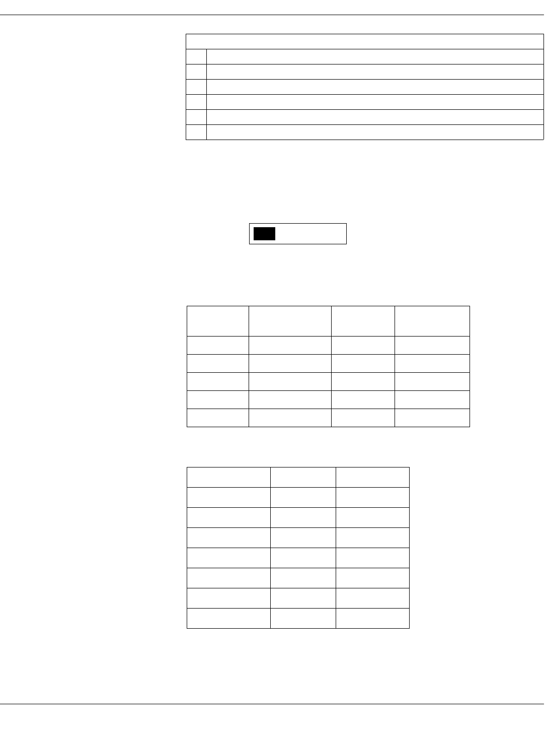
80 APEX, ApexPro, and ApexPro CH Transmitter Programming Instructions Revision A - Draft 7
2001989-135
ApexPro Transmitter
5. To exit the Super User mode, select the Communication status button
again.
Appendix 3: ApexPro TTX Labels and Frequencies
Transmitters used with ApexPro systems require TTX labels that have this
format:
Frequencies available for ApexPro transmitters are in these ranges:
600 MHz
400 MHz
Table 9. Program ApexPro Transmitter Technical Functions Window
Ref Definition
AOptional Features selected
BIQ Table version
CCommunication status button
DDownload Functions available
EDiagnostic test results
U.S. TV
Channel Frequency (MHz) TTX# Range ApexPro V2 PN
33 584.025 - 589.975 7561 - 7799 2009840-005
34 590.025 - 595.975 7801 - 8039 2009840-006
35 596.025 - 601.975 8041 - 8279 2009840-007
36 602.025 - 607.975 8281 - 8519 2009840-008
37 608.025 - 613.975 8521 - 8759 2009840-009
Frequency (MHz) TTX# Range ApexPro V2 PN
420.000 - 425.950 1000-1238 2009841-001
425.975 - 431.925 1239-1477 2009841-002
431.950 - 437.900 1478-1716 2009841-003
437.925 - 443.875 1717-1955 2009841-004
443.900 - 449.850 1956-2194 2009841-005
449.875 - 455.825 2195-2433 2009841-006
455.850 - 460.000 2434-2600 2009841-007
XXXXAP (XXXX)
TTX
Draft

Revision A - Draft 7 APEX, ApexPro, and ApexPro CH Transmitter Programming Instructions 81
2001989-135
ApexPro Transmitter
For your notes
Draft

82 APEX, ApexPro, and ApexPro CH Transmitter Programming Instructions Revision A - Draft 7
2001989-135
ApexPro Transmitter
Draft
Draft

World Headquarters
GE Medical Systems
Information Technologies
, Inc.
8200 West Tower Avenue
Milwaukee, WI 53223 USA
Tel: +414.355.5000
800.558.5120 (US only)
Fax: +414.355.3790
European Representative
GE Medical Systems
Information Technologies
GmbH
Postfach 60 02 65
D-79032 Freiburg
Germany
Tel: +49 761 45 43 - 0
Fax: +49 761 45 43 - 233
Asia Region
GE Medical Systems Asia
7-127, Asahigaoka 4-chome
Hino-shi, Tokyo 191-8503
Japan
Tel: +81-42-582-6824
Fax: +81-42-582-6830
0459
gemedical.com
Draft