GE Medical Systems Information Technologies 5406102 URP Detector UWB Radio PWA and Antenna Module User Manual Optima220 5400222 1EN
GE Medical Systems Information Technologies Inc. URP Detector UWB Radio PWA and Antenna Module Optima220 5400222 1EN
Users Manual

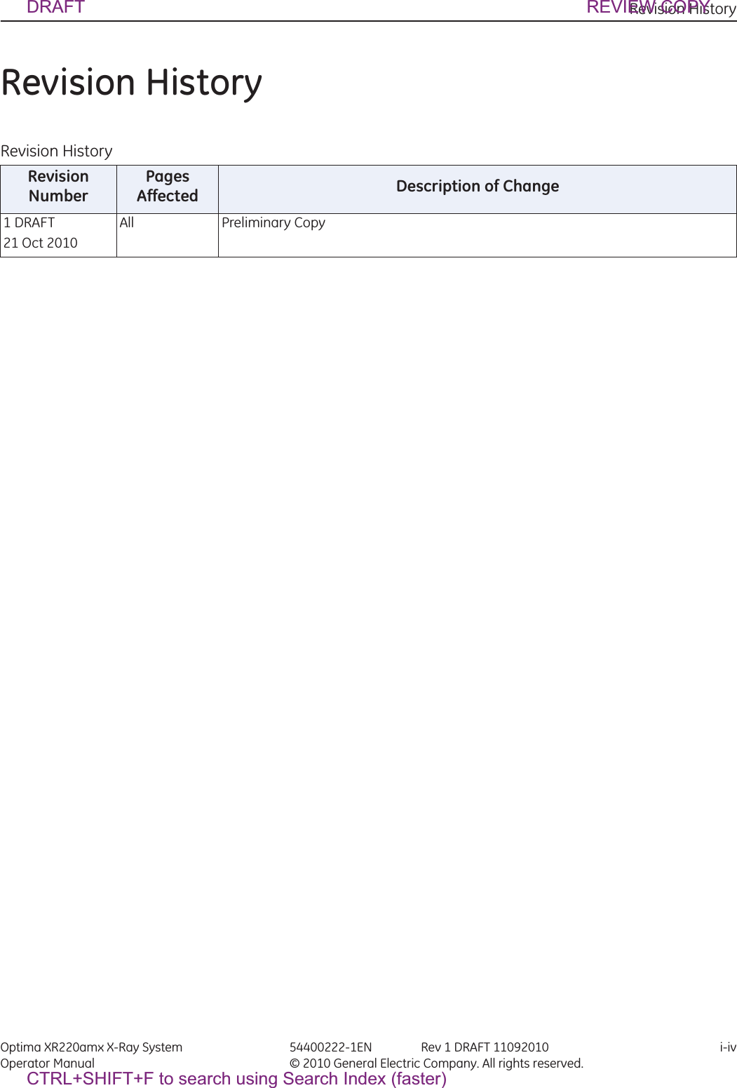
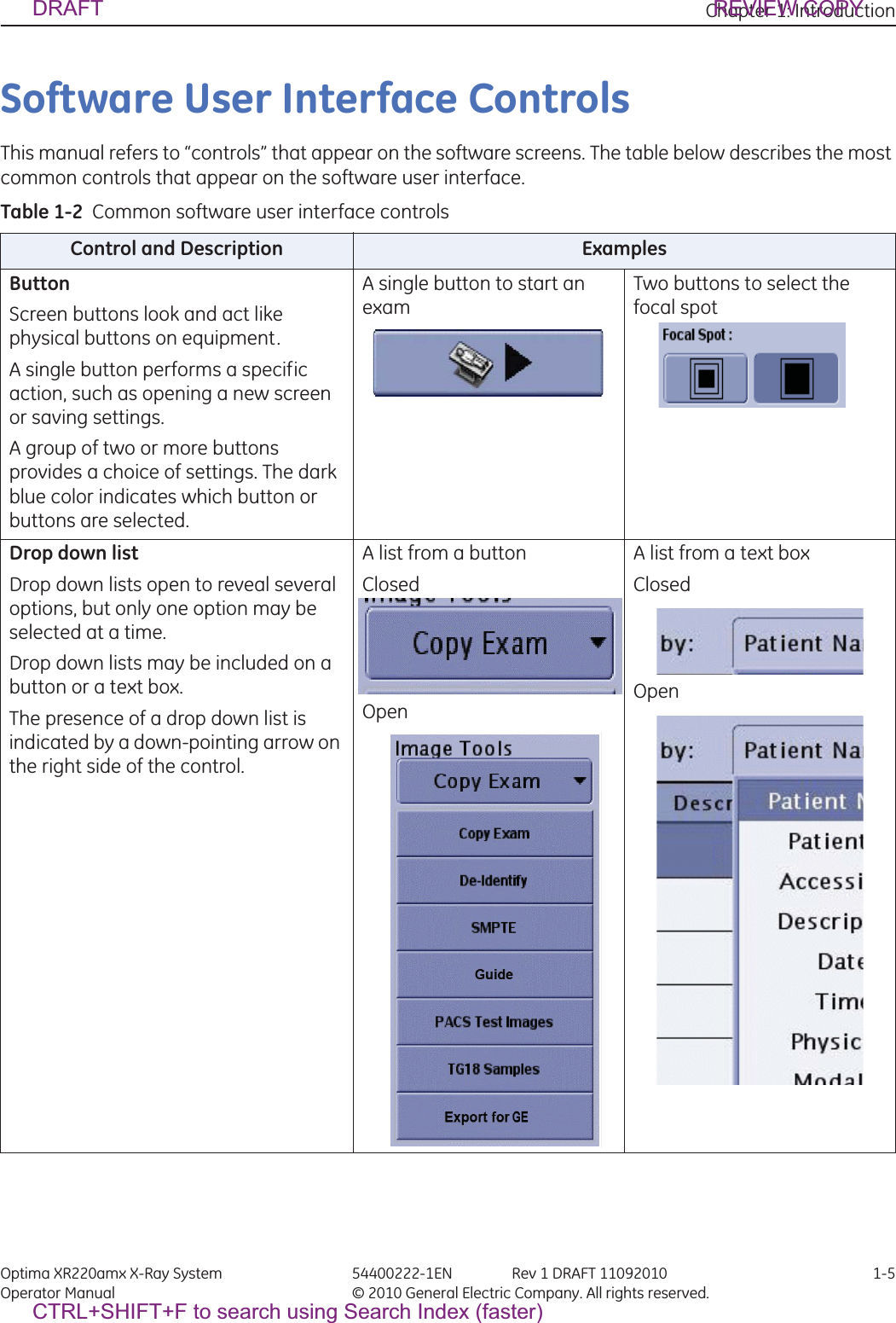
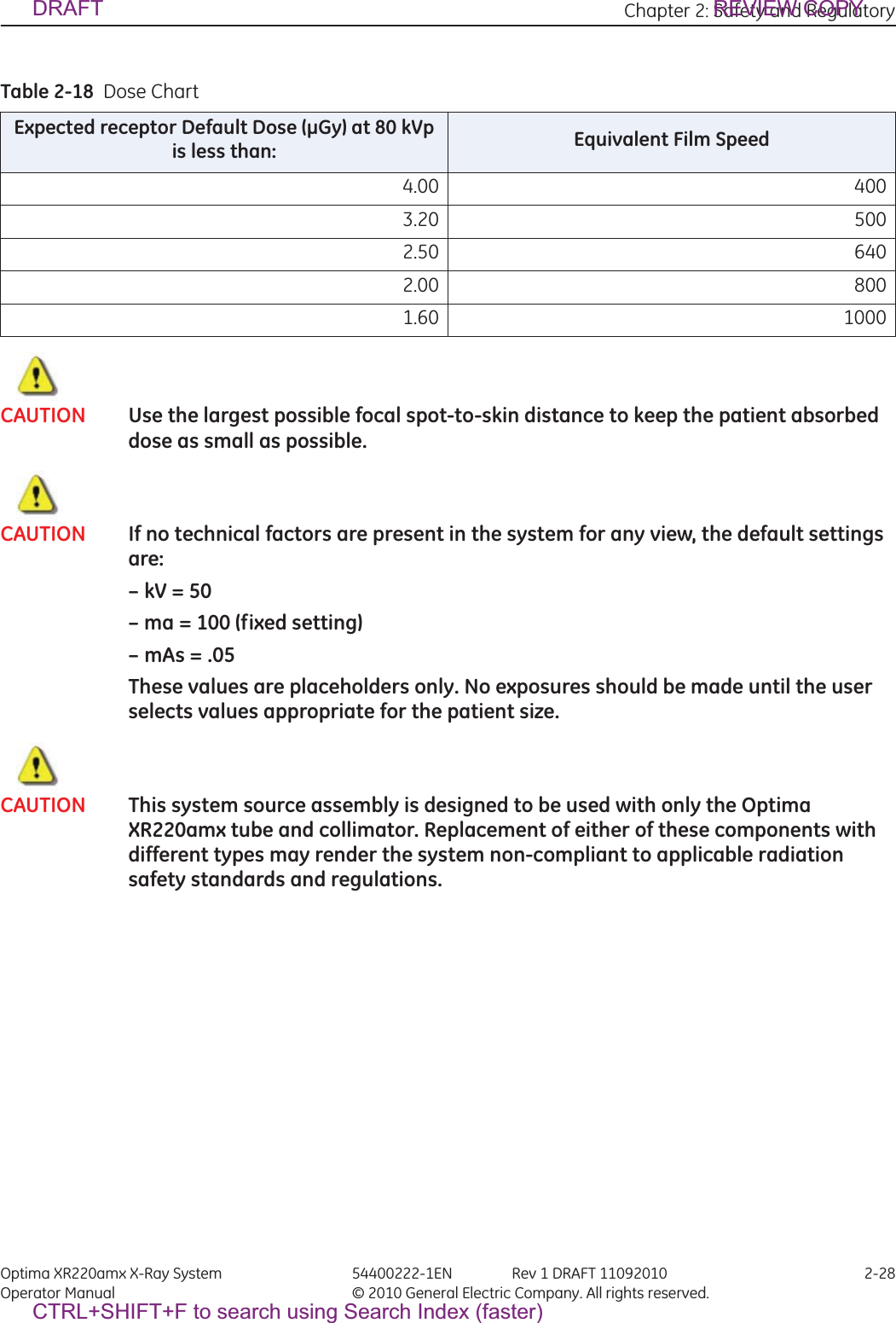
![Chapter 1: Introduction Optima XR220amx X-Ray System 54400222-1EN Rev 1 DRAFT 11092010 1-4Operator Manual © 2010 General Electric Company. All rights reserved.Graphic Conventions and LegendsThe table below describes the conventions used when working with menus, buttons, text boxes and key-board keys.Table 1-1 Conventions for menus, buttons, text boxes, and keyboard keysExample DescribesSelect Marking an option in a group of check boxes or radial buttonsChoosing an option from a drop-down listActivating a tabHighlighting row itemsPress [START EXAM] Pressing a button on a screen.Press ENTER Pressing a key on the keyboard.Press CTRL+ALT+DELETE Pressing a combination of keys on the keyboard. The key that should be pressed first is listed first.Press and hold SHIFT Pressing and holding down a key on the keyboard.In the Matrix text box,... The name of text box in which you can select or type text or the name of a drop-down list from which you select an option.Type DICOMAE in the... Text you enter into a text box.Select Preferences > Worklist.The path of selecting option(s) in a tree structure.DRAFT REVIEW COPYCTRL+SHIFT+F to search using Search Index (faster)](https://usermanual.wiki/GE-Medical-Systems-Information-Technologies/5406102/User-Guide-1377025-Page-9.png)
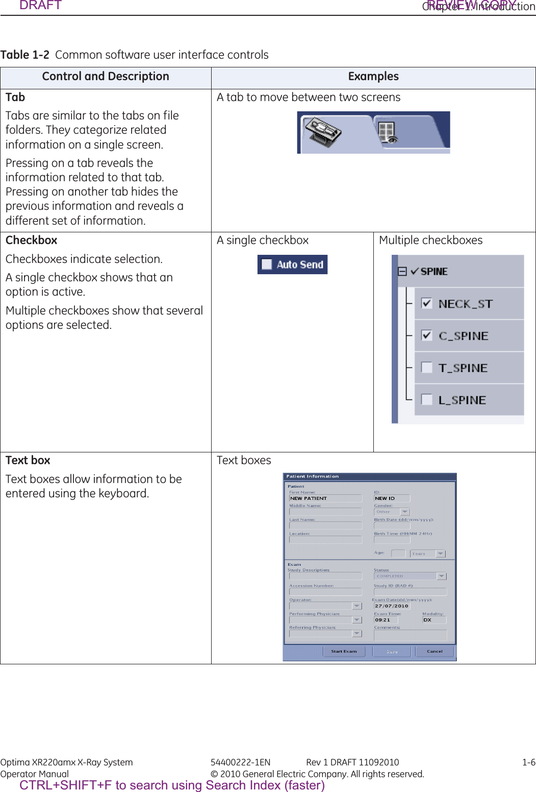

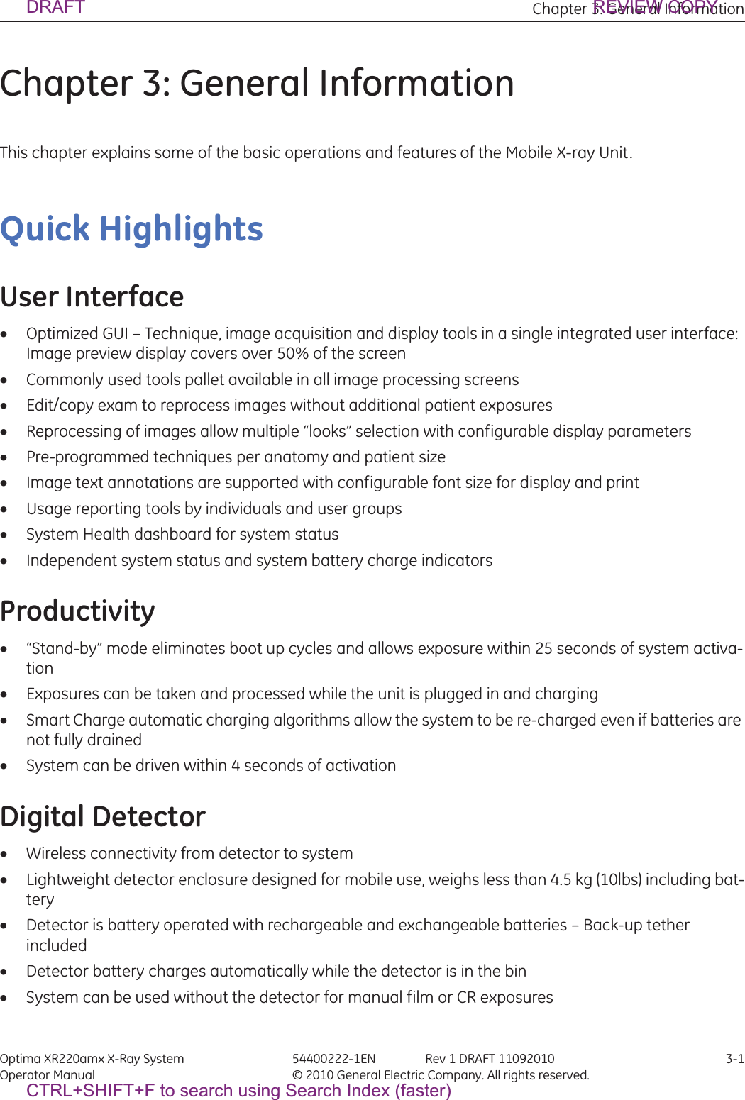
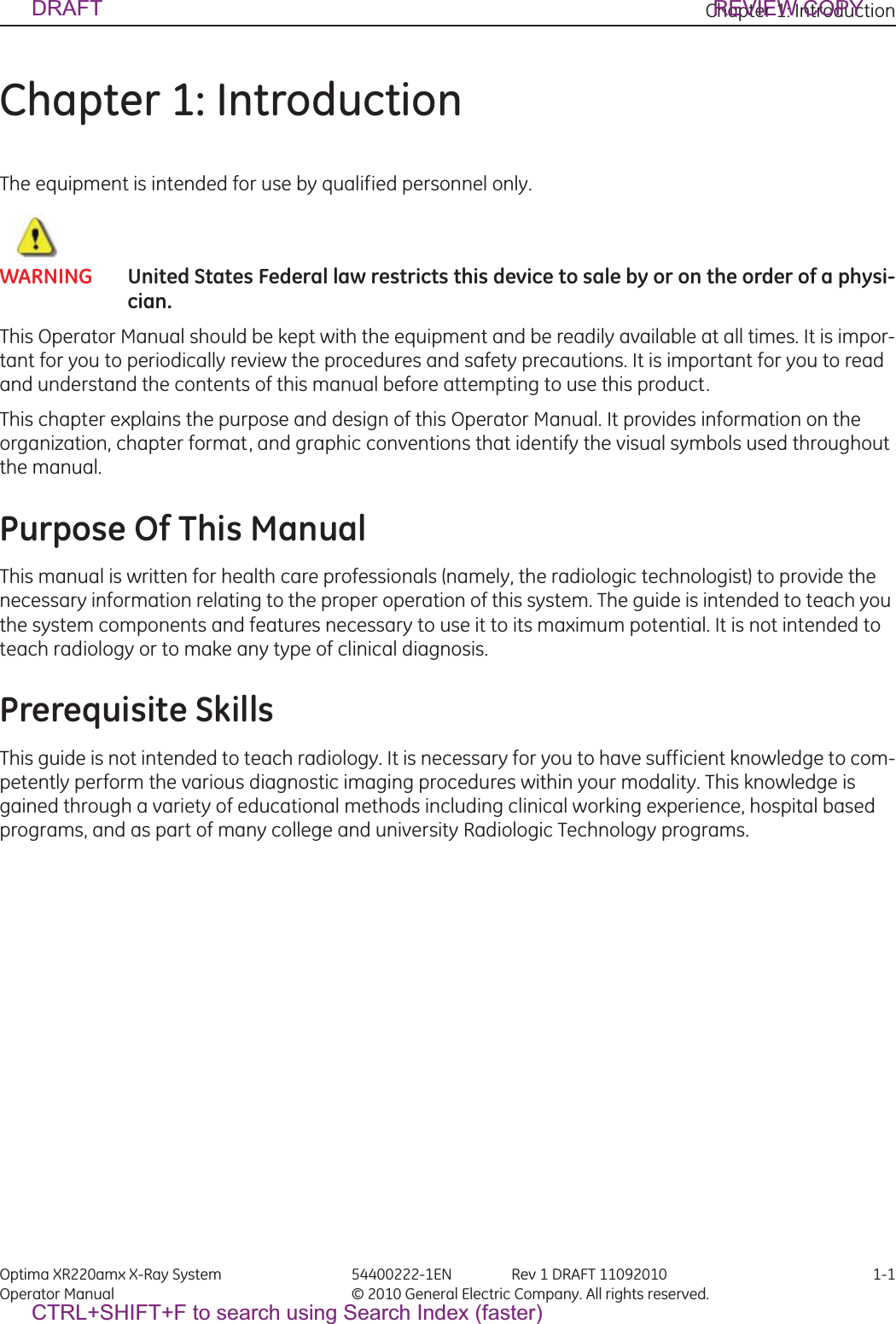
![Appendix A: Login Administration Optima XR220amx X-Ray System 54400222-1EN Rev 1 DRAFT 11092010 A-1Operator Manual © 2010 General Electric Company. All rights reserved.Appendix A: Login AdministrationLogin and LogoutThe login feature requires you to login to access the system and can be turned on or off by your administrator or Field Engineer.How your site uses this feature depends on if your site has a central user repository to which the system is connected. Sites with networks are referred to as Enterprise systems, those without are referred to as stand-alone systems. This feature can be used with either configuration, although some features are more applicable to enterprise systems.1. At the login screen, type your assigned login name.xThis name is assigned by your system administrator.Note: If you need to log in quickly for emergency purposes only, press [Emergency Login].Note: Logging off does not prohibit other users from logging in. Logout is designed to protect patient pri-vacy, not stop approved users from logging in. When you or another user logs back in, the system returns to its last known state.2. Press in the Password area and type in your password.3. Press [Login].Figure A-1 Login Window4. To logout of the system, press [Shutdown].xThe Shutdown window appears.5. Press [Logout User].6. Press [OK].DRAFT REVIEW COPYCTRL+SHIFT+F to search using Search Index (faster)](https://usermanual.wiki/GE-Medical-Systems-Information-Technologies/5406102/User-Guide-1377025-Page-59.png)
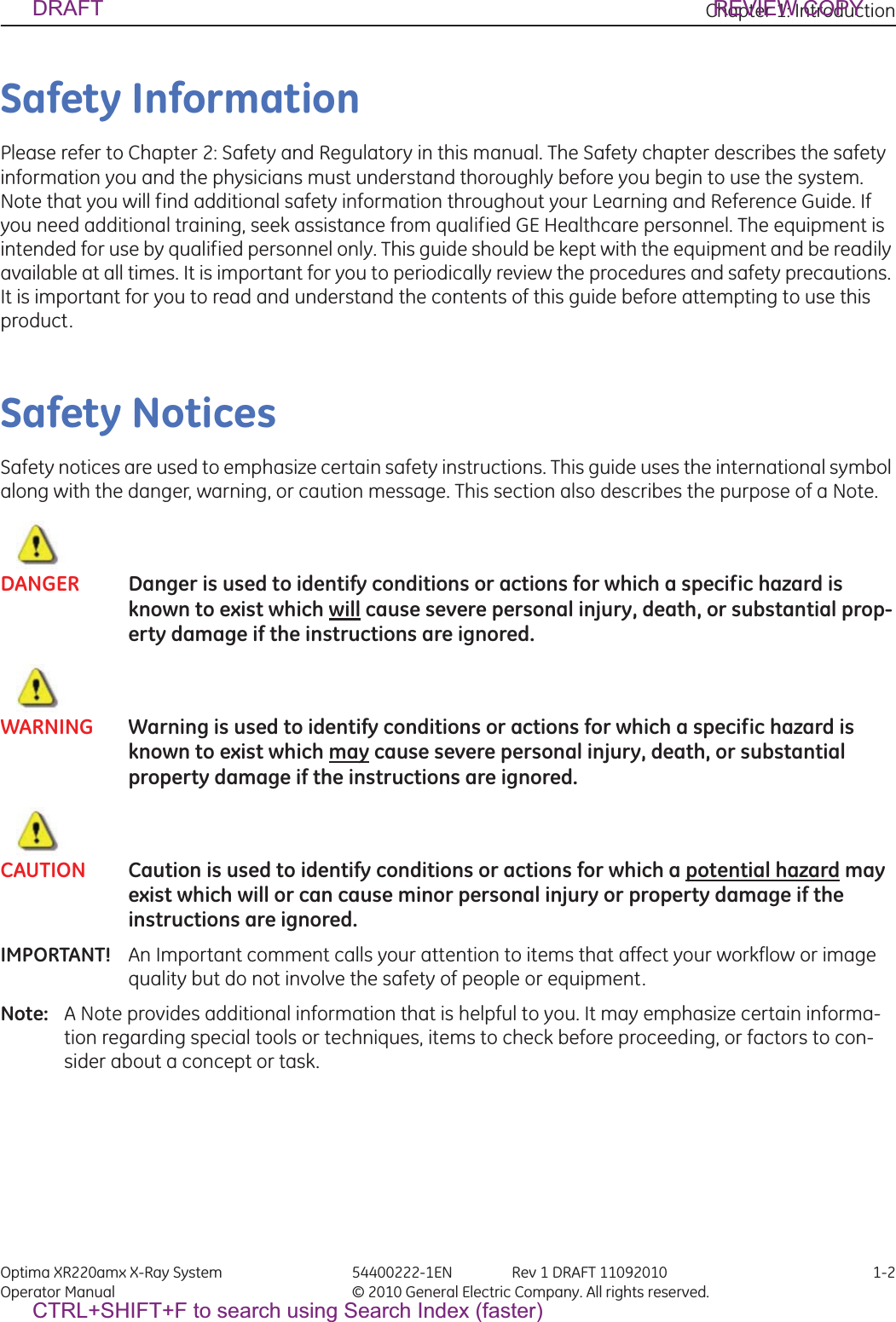
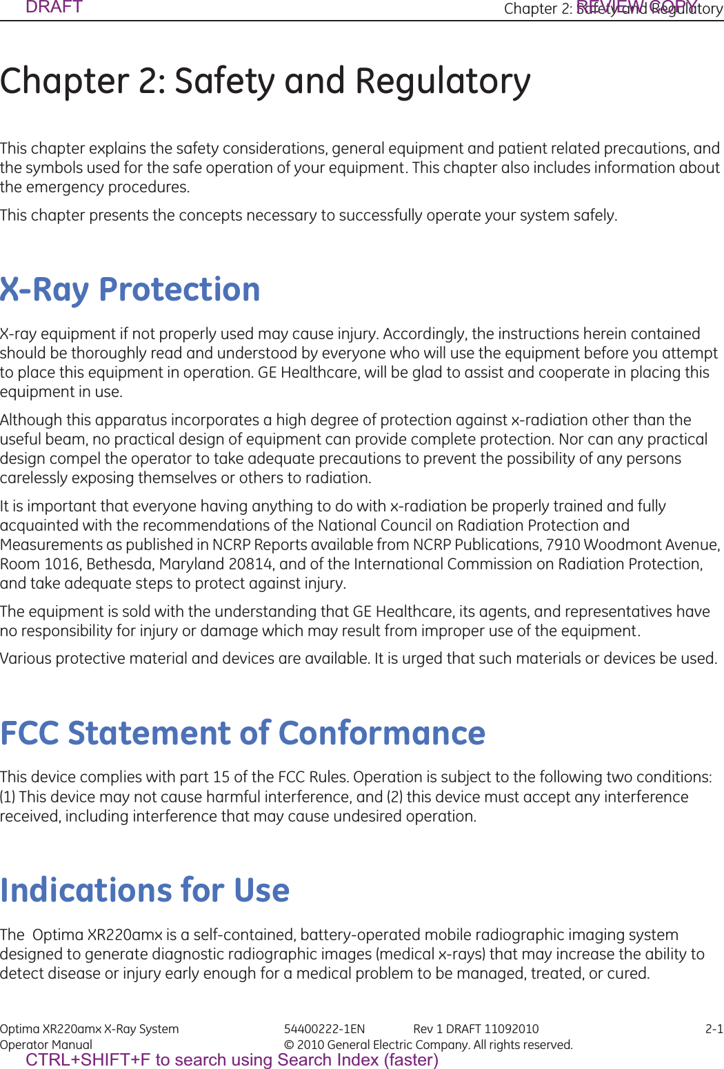
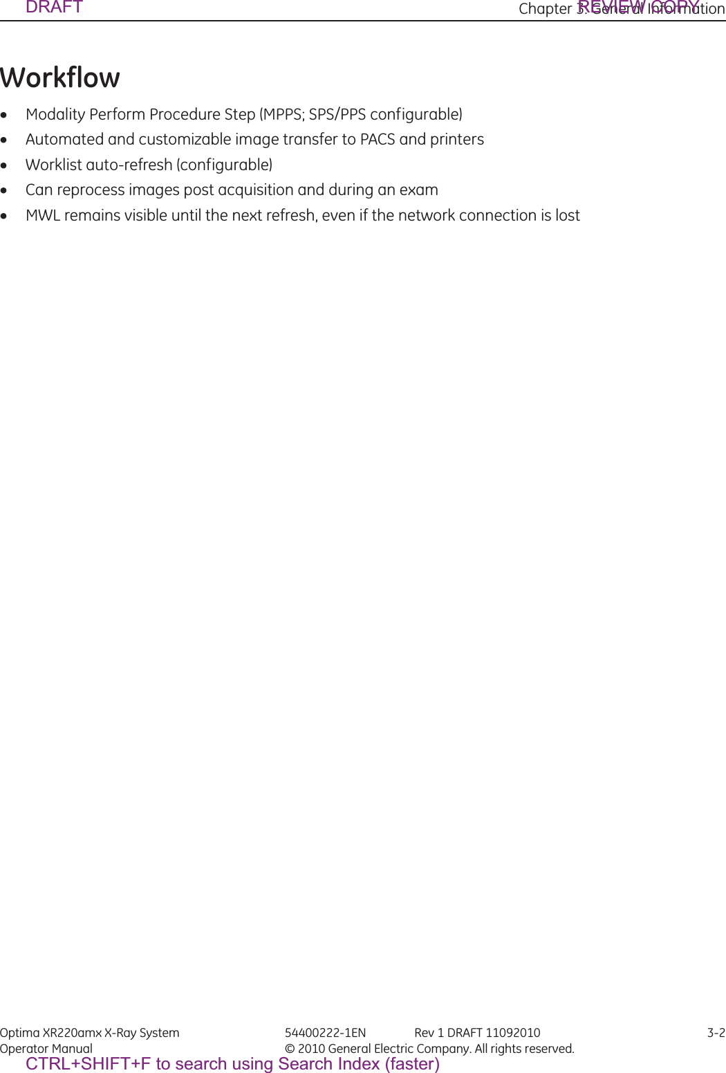
![Appendix A: Login Administration Optima XR220amx X-Ray System 54400222-1EN Rev 1 DRAFT 11092010 A-2Operator Manual © 2010 General Electric Company. All rights reserved.xThe system logs you out and waits for the next login.Configure HIPAA (EA3) PropertiesAfter logging in, the component will display the Application Tab. On this tab, you will be able to configure EA3 application properties. 1. Press [Utilities].Figure A-2 2. Press Service [Launch] on the System Utilities screen.Figure A-3 Service Toolbar3. Select EA3 Admin BrowserFigure A-4 EA3 Admin BrowserxThis brings up the Administration Screen.DRAFT REVIEW COPYCTRL+SHIFT+F to search using Search Index (faster)](https://usermanual.wiki/GE-Medical-Systems-Information-Technologies/5406102/User-Guide-1377025-Page-60.png)
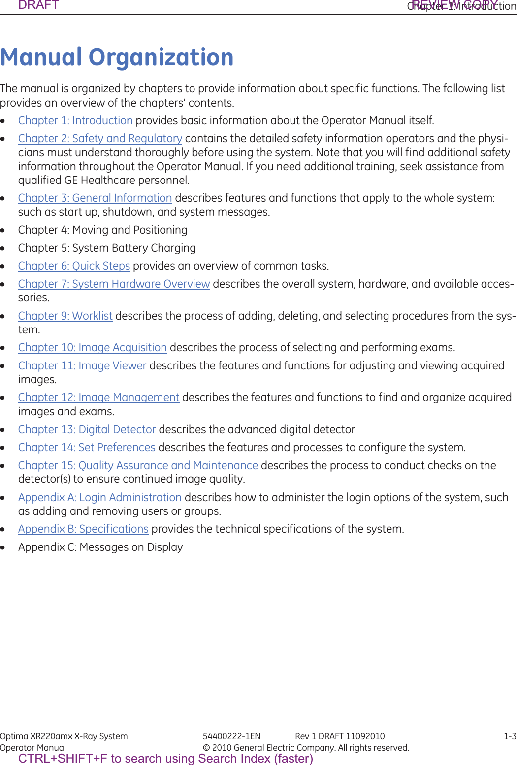
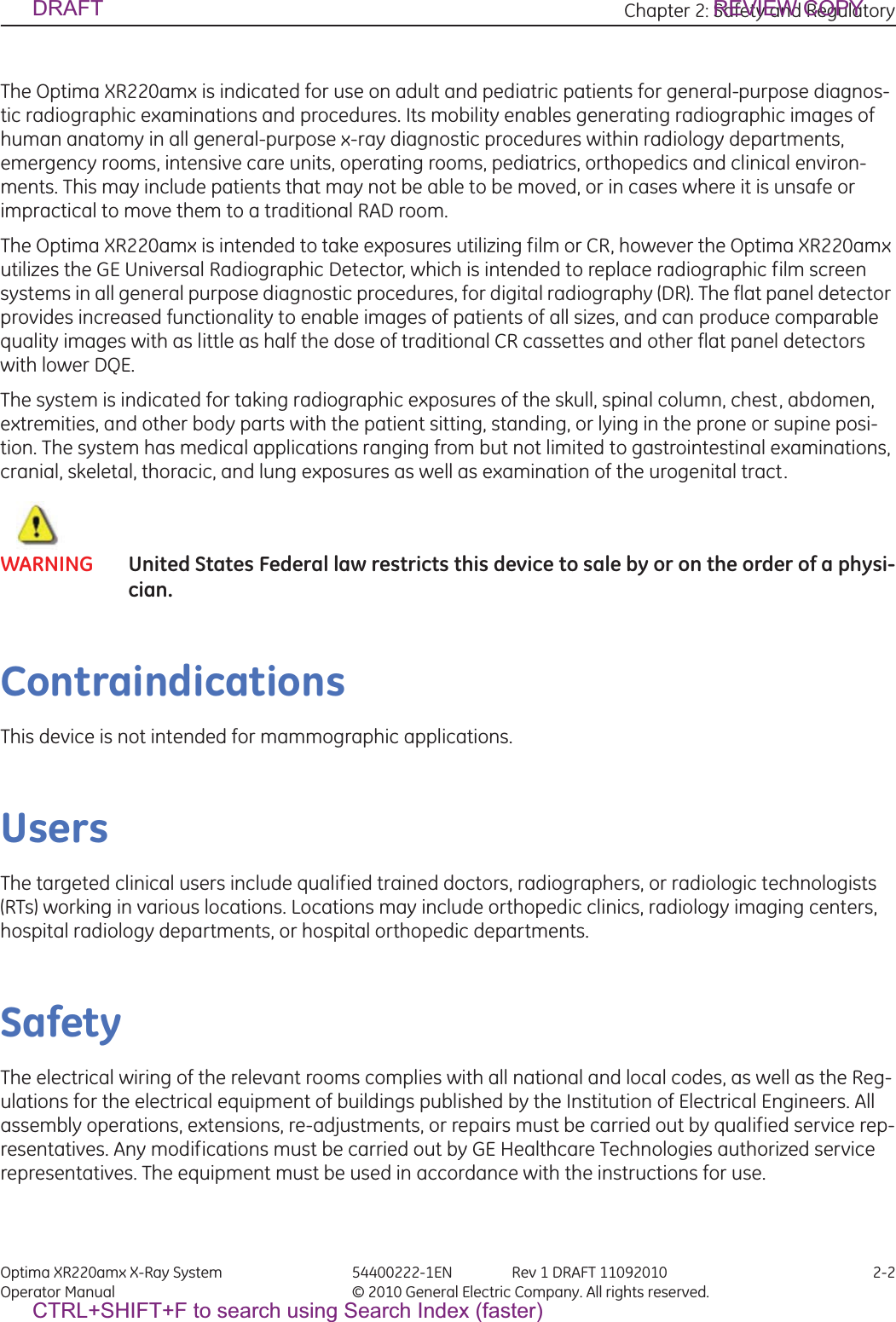
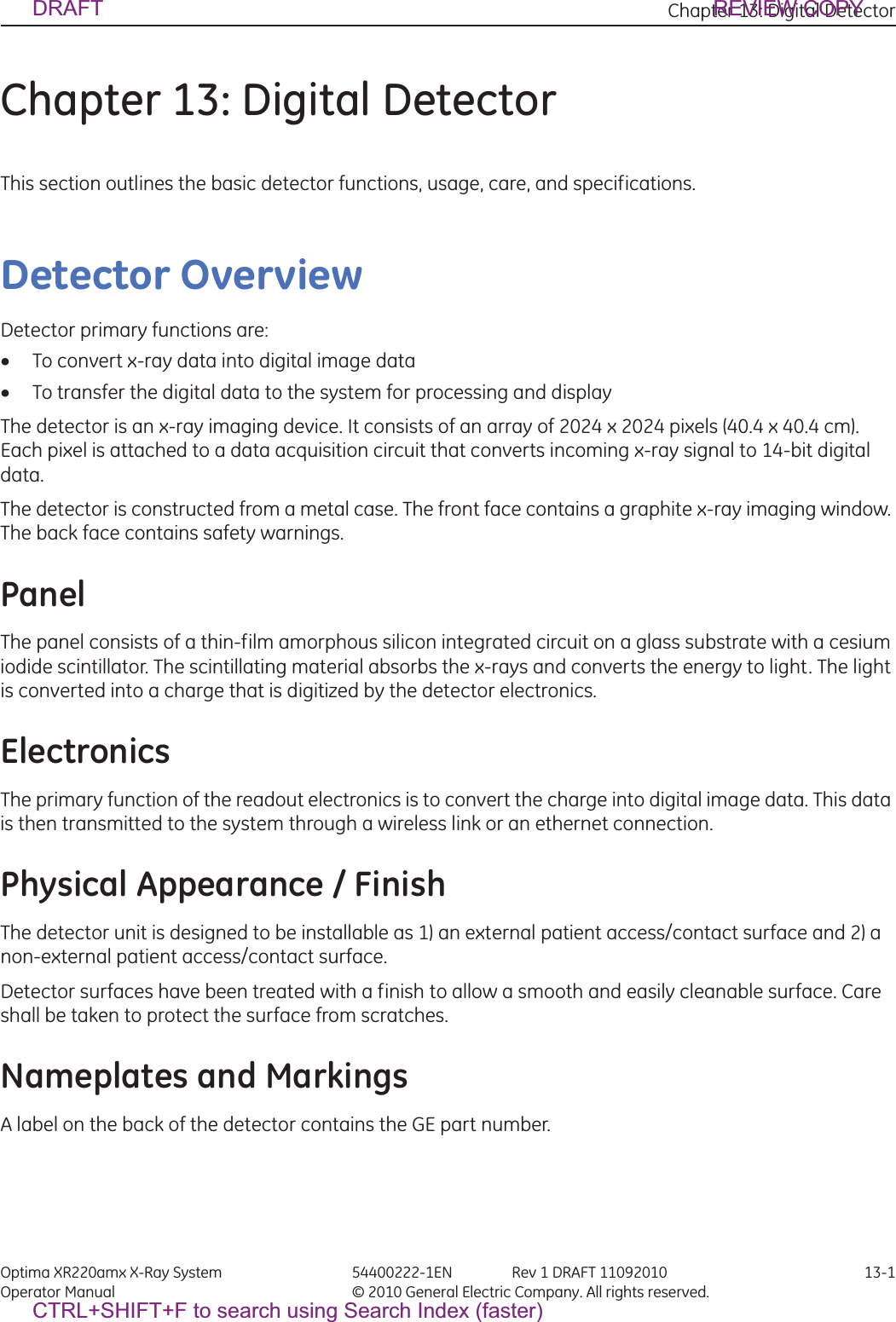
![Appendix A: Login Administration Optima XR220amx X-Ray System 54400222-1EN Rev 1 DRAFT 11092010 A-3Operator Manual © 2010 General Electric Company. All rights reserved.Figure A-5 Administration Tab4. Enter your Username and Password.5. Press [Login].DRAFT REVIEW COPYCTRL+SHIFT+F to search using Search Index (faster)](https://usermanual.wiki/GE-Medical-Systems-Information-Technologies/5406102/User-Guide-1377025-Page-61.png)
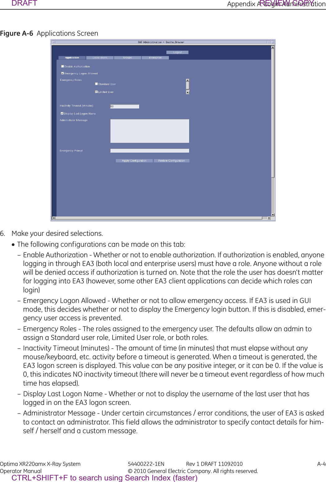
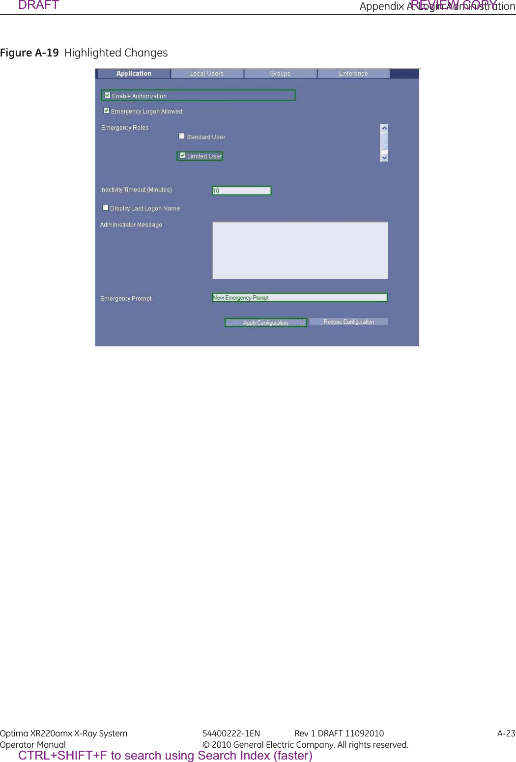
![Appendix A: Login Administration Optima XR220amx X-Ray System 54400222-1EN Rev 1 DRAFT 11092010 A-5Operator Manual © 2010 General Electric Company. All rights reserved.– Emergency Prompt - The text that will be displayed to any user logging in as emergency. The user is asked to enter information (usually their actual user name). This text is the text that will appear in that prompt for information. 7. Press [Apply Configuration].xTo make a configuration change, make the necessary changes on the fields, and press the Apply Configuration button. If there was a problem with making the changes (such as an invalid value or a problem contacting the back-end Servlet) you will see a message box indicating this error with a description of the error. If the changes are successful, after the 'Apply Configuration' button is pressed, then you will see a brief message indicating that the changes were applied in a green label. If at any time, you want to revert your changes to what is currently saved on the back-end, you can press the Restore Configuration button. This will undo any changes that you have made that have not yet been saved by pressing the Apply Configuration Button. (Once you press the 'Apply Configuration' button and get the confirmation label, the changes have been applied). DRAFT REVIEW COPYCTRL+SHIFT+F to search using Search Index (faster)](https://usermanual.wiki/GE-Medical-Systems-Information-Technologies/5406102/User-Guide-1377025-Page-63.png)
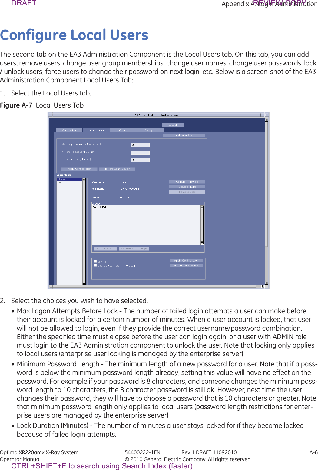
![Appendix A: Login Administration Optima XR220amx X-Ray System 54400222-1EN Rev 1 DRAFT 11092010 A-7Operator Manual © 2010 General Electric Company. All rights reserved.x Apply Configuration - Use the Apply Configuration button to save changes.xRestore Configuration - Use this button to undo any changes that have not been saved yet. If there are any errors, you will get a popup box describing the error. If it is successful, you will see a green label appear with confirmation information.Note: Users can become locked in one of two ways.-The user enters too many incorrect passwords. In this case, the user will be locked out for a certain amount of time, even with a correct password. Once the time has elapsed, the user can attempt a login again. An administrator can unlock this user before the lock duration time has elapsed by un checking Locked under the Local User tab when a user is selected.-The administrator forcefully locks the user account. In this case, the lock duration does not apply to a user who was forcefully locked by and administrator. They are locked until the administration unlocks them. 3. Press [Apply Configurations].DRAFT REVIEW COPYCTRL+SHIFT+F to search using Search Index (faster)](https://usermanual.wiki/GE-Medical-Systems-Information-Technologies/5406102/User-Guide-1377025-Page-65.png)
![Appendix A: Login Administration Optima XR220amx X-Ray System 54400222-1EN Rev 1 DRAFT 11092010 A-8Operator Manual © 2010 General Electric Company. All rights reserved.Add a Local UserOnce a user is added, it is automatically highlighted in the Local Users list box on the left-hand site, and it is 'in context'. Once a user is in context, all information and buttons in the center panel (i.e. Username, Full Name, Roles, Change Name, Change Password, Remove User, Groups list box, Add To Groups Button, and Remove From Groups button) refer to that user.1. Press [Add Local User].xWhen this button is pressed a popup panel is displayed.2. Enter the new User ID (which must be unique).3. Enter a Full Name.4. Enter a Password.5. Enter the Confirmed Password.xIf any errors are encountered, you will receive an error messagebox. If you receive the error mes-sagebox, changes were not committed to the database, and you can correct your errors and try again. Possible errors that can be encountered when adding a user are: – User ID already exists in the local user database (Choose a different unique username) – Password does not meet the minimum length requirements (Choose a longer password) – Password and Confirm Password box do not match (Make sure the passwords match) 6. Press [Add User].Figure A-8 Add User ScreenDRAFT REVIEW COPYCTRL+SHIFT+F to search using Search Index (faster)](https://usermanual.wiki/GE-Medical-Systems-Information-Technologies/5406102/User-Guide-1377025-Page-66.png)
![Appendix A: Login Administration Optima XR220amx X-Ray System 54400222-1EN Rev 1 DRAFT 11092010 A-9Operator Manual © 2010 General Electric Company. All rights reserved.Change a User PasswordYou can select a user to be 'in context' by pressing on the user's id in the 'Local Users' list box on the left side. Only one user can be in context at a time, and if you attempt to choose multiple users, EA3 will select the top-most user that is selected. Once a user is 'in context', you can make any necessary modifi-cations to that user. Note: When you first navigate to the Local Users tab, EA3 will put the first listed local user 'in context' automatically. If there are no local users then there will be no user in context, and all of the but-tons in the center panel will be disabled until a user is added. 1. Select User.2. Press [Change Password]. xThis brings up a popup panel with two textboxes for the password.3. Make changes to the password.4. Press [Confirm Change]. xIf you do not want to make the change, simply press Cancel. xIf the password doesn't meet the minimum length requirements, you will receive an error message-box. If this occurs, your changes were not saved. Simply make the necessary corrections, and press Confirm Change again. Figure A-9 Change PasswordDRAFT REVIEW COPYCTRL+SHIFT+F to search using Search Index (faster)](https://usermanual.wiki/GE-Medical-Systems-Information-Technologies/5406102/User-Guide-1377025-Page-67.png)
![Appendix A: Login Administration Optima XR220amx X-Ray System 54400222-1EN Rev 1 DRAFT 11092010 A-10Operator Manual © 2010 General Electric Company. All rights reserved.Change a User Full Name1. Select User.2. Press [Change Name].3. Make changes to the name.4. Press [Confirm Change].xIf you do not want to make the change, simply press the Cancel button.Figure A-10 Change NameDRAFT REVIEW COPYCTRL+SHIFT+F to search using Search Index (faster)](https://usermanual.wiki/GE-Medical-Systems-Information-Technologies/5406102/User-Guide-1377025-Page-68.png)
![Appendix A: Login Administration Optima XR220amx X-Ray System 54400222-1EN Rev 1 DRAFT 11092010 A-11Operator Manual © 2010 General Electric Company. All rights reserved.Remove a User1. Select User.2. Press [Remove User].3. Press [Confirm Removal].xIf you do not want to make the change, simply press the Cancel button.Figure A-11 Confirm RemovalDRAFT REVIEW COPYCTRL+SHIFT+F to search using Search Index (faster)](https://usermanual.wiki/GE-Medical-Systems-Information-Technologies/5406102/User-Guide-1377025-Page-69.png)
![Appendix A: Login Administration Optima XR220amx X-Ray System 54400222-1EN Rev 1 DRAFT 11092010 A-12Operator Manual © 2010 General Electric Company. All rights reserved.Add or Remove a User from a GroupAll of the groups to which this user belongs are listed in the Groups list box.1. Press [Add To Groups] or press [Remove From Groups].xThis brings up a popup panel that lists all of the groups that this user is eligible to be added to. If there are no groups that this user is eligible to be added to, you will get an error message box instead of the popup panel. Once you get the popup panel, simply select all of the groups to which you want to add this user (you can select as many as you want at one time).2. Press [Add Membership] or press [Remove Membership].Figure A-12 Add GroupsFigure A-13 Remove GroupDRAFT REVIEW COPYCTRL+SHIFT+F to search using Search Index (faster)](https://usermanual.wiki/GE-Medical-Systems-Information-Technologies/5406102/User-Guide-1377025-Page-70.png)
![Appendix A: Login Administration Optima XR220amx X-Ray System 54400222-1EN Rev 1 DRAFT 11092010 A-15Operator Manual © 2010 General Electric Company. All rights reserved.Configure GroupsThe third tab on the EA3 Administration Component is the Groups tab. On this tab, you can add local groups, add enterprise groups, remove local groups, remove enterprise groups, change group roles, and change group memberships.1. Press [Groups].Figure A-14 Groups windowDRAFT REVIEW COPYCTRL+SHIFT+F to search using Search Index (faster)](https://usermanual.wiki/GE-Medical-Systems-Information-Technologies/5406102/User-Guide-1377025-Page-73.png)
![Appendix A: Login Administration Optima XR220amx X-Ray System 54400222-1EN Rev 1 DRAFT 11092010 A-16Operator Manual © 2010 General Electric Company. All rights reserved.Add a Local Group1. Press [Add Local Group].xWhen this button is pressed a popup panel is displayed.2. Enter the new group's name (which must be unique).xIf any errors are encountered, you will receive an error message box. If you receive the error mes-sage box, changes were not saved to the database, and you can correct your errors and try again. Possible errors that can be encountered when adding a group are: – Group name already exists in the database – Application session timeout xOnce a local group is added, it is automatically highlighted in the Local Groups list box on the left-hand site, and it is highlighted. Once a group is highlighted, all information and buttons in the cen-ter panel (i.e. Group Name, Remove Group Button, Roles checkboxes, Apply Roles button, Group Members list box, Add Membership button, and Remove Membership button) refer to that group.Figure A-15 Add Group3. Press [Add Group].Add a Enterprise GroupAdding an Enterprise group is quite similar to adding a local group.1. Press [Add Enterprise Group].x2. When this button is pressed a popup panel is displayed.xIf any errors are encountered, you will receive an error message box. If you receive the error mes-sage box, changes were not saved to the database, and you can correct your errors and try again. Possible errors that can be encountered when adding a group are: – Group name already exists in the database – Application session timeout 3. Press [Add Group].xAdding an enterprise group doesn't actually add a group to the Enterprise directory server. What it does is give EA3 the ability to manage roles for that group, which should already exist on the Enter-prise directory server. So, for example, if you add a group 'All Employees' as an Enterprise group to DRAFT REVIEW COPYCTRL+SHIFT+F to search using Search Index (faster)](https://usermanual.wiki/GE-Medical-Systems-Information-Technologies/5406102/User-Guide-1377025-Page-74.png)
![Appendix A: Login Administration Optima XR220amx X-Ray System 54400222-1EN Rev 1 DRAFT 11092010 A-17Operator Manual © 2010 General Electric Company. All rights reserved.EA3, and assign that group with the STANDARD role, then any enterprise user that logs in through EA3 and belongs to the 'All Employees' group will have the STANDARD role. xYou cannot manage the group memberships for Enterprise groups. This is managed by the direc-tory server, not EA3. Therefore, whenever an Enterprise group is in context, both the 'Add Member-ship' and 'Remove Membership' buttons will be blocked out. This doesn't mean that no one belongs to the Enterprise groups, just that this is managed by the directory server and not EA3. xOnce an enterprise group is added, it is automatically highlighted in the Enterprise Groups list box on the left-hand site, and it is 'in context'. Once a group is in context, all information and buttons in the center panel (i.e. Group Name, Remove Group Button, Roles checkboxes, Apply Roles button, Group Members list box) refer to that group. Figure A-16 Add Enterprise GroupManage a GroupYou can select a group to be highlighted by pressing on the group's name in either the 'Local Groups' or the 'Enterprise Groups' list box on the left side. Only one group can be highlighted at a time, and if you attempt to choose multiple groups, EA3 will automatically select the top-most group that is selected. Once a group is highlighted, you can make any necessary modifications to that group. Note: When you first navigate to the Groups tab, EA3 will put the first listed local group highlighted automatically. If there are no local groups, then EA3 will put the first listed enterprise group high-lighted automatically. if there are no local groups or enterprise groups, then there will be no group highlighted, and all of the buttons in the center panel will be disabled until a group is added. Remove a Group1. Once a group is highlighted, press [Remove Group]. xThis brings up a popup panel asking you to confirm the removal of the group.2. If you want to remove the group, press [Confirm Removal]. xIf you do not want to remove the group, simply press [Cancel]. DRAFT REVIEW COPYCTRL+SHIFT+F to search using Search Index (faster)](https://usermanual.wiki/GE-Medical-Systems-Information-Technologies/5406102/User-Guide-1377025-Page-75.png)
![Appendix A: Login Administration Optima XR220amx X-Ray System 54400222-1EN Rev 1 DRAFT 11092010 A-18Operator Manual © 2010 General Electric Company. All rights reserved.Figure A-17 Remove GroupChange Group’s RolesOnce a group is highlighted, check or uncheck the checkboxes for the Roles you want to give to this group, and press [Apply Roles]. There is a green label confirmation as usual for successfully applied roles. If there is a failure on the back-end (i.e. a problem writing the roles configuration changes), you will receive an error message box with information. Add Memberships1. Once a group is highlighted, press [Add Membership]. xThis brings up a popup panel that lists all of the users that are eligible to be added to this group. If there are no users eligible to be added to this group, you will get an error message box instead of the popup panel. Once you get the popup panel, simply select all of the users that you want to add to this group (you can select as many as you want at one time).2. Press [Add Membership]. xIf you do not want to remove the group, simply press [Cancel]. Remove Memberships1. Once a group is highlighted, press [Remove Membership]. xThis brings up a popup panel that lists all of the users that are eligible to be removed from this group. If there are no users eligible to be removed from this group, you will get an error message box instead of the popup panel. Once you get the popup panel, simply select all of the users that you want to remove from this group (you can select as many as you want at one time).2. Press [Remove Membership]. xIf you do not want to remove the group, simply press [Cancel]. DRAFT REVIEW COPYCTRL+SHIFT+F to search using Search Index (faster)](https://usermanual.wiki/GE-Medical-Systems-Information-Technologies/5406102/User-Guide-1377025-Page-76.png)
![Appendix A: Login Administration Optima XR220amx X-Ray System 54400222-1EN Rev 1 DRAFT 11092010 A-19Operator Manual © 2010 General Electric Company. All rights reserved.Configure Enterprise TabThe last tab on the EA3 Administration Component is the Enterprise tab. On this tab, you can configure the properties necessary to make a connection to an Enterprise directory server (i.e. MSAD, Novell, etc.).The Enterprise Tab is used by the site’s IT (Information Technology) or GE Service personnel. It provides connectivity to the site’s user database. If you do not have a network established in your hospital or clinic, this tab will not be used.Things to consider:xUtilize the enterprise capability whenever possible.xMake sure the enterprise groups are granular enough to restrict protocol edit access.xThe inactivity timeout should be turned on.1. Press [Enterprise].Figure A-18 Enterprise TabThe following configurations can be made on the top box of this tab: xEnable Enterprise Authentication - Whether or not Enterprise users should be able to log in. If this is unchecked, only local EA3 users will be able to log in. If this is checked, both local users and enter-prise EA3 users will be able to log in (although the local EA3 user database will always be tried first). xCache Enterprise Users - Whether or not Enterprise users should be cached once they successfully login. If this is checked, then a local record of an Enterprise user is kept. If at any time that user attempts to login again, and for some reason the Enterprise directory server is not available (i.e. net-work problems), that user will be granted access if they provide the correct password. If this is unchecked, then an Enterprise user will be denied access in the case that the Enterprise directory DRAFT REVIEW COPYCTRL+SHIFT+F to search using Search Index (faster)](https://usermanual.wiki/GE-Medical-Systems-Information-Technologies/5406102/User-Guide-1377025-Page-77.png)
![Appendix A: Login Administration Optima XR220amx X-Ray System 54400222-1EN Rev 1 DRAFT 11092010 A-20Operator Manual © 2010 General Electric Company. All rights reserved.server cannot be reached. Note that hashed passwords are cached, the actual password is not cached. xEnterprise Authentication Latency (Seconds) - The amount of time (in seconds) that the EA3 login pro-cess should wait for a response from the Enterprise directory server. Often times, there is a network latency when connecting to servers, and it will be different on different network configurations. If the amount of time is reached without a response from the directory server, the EA3 login process will return a failed login. A value of 5 seconds should be enough time to allow a properly configured direc-tory server to respond, without being too much of an annoyance to the user if the directory server is down (i.e. they will only have to wait at a maximum 5 seconds for the login attempt to return). xApplying configuration changes on the Enterprise tab top box are the same as mentioned before for the Application tab. Use the Apply Configuration button to commit changes, and the Restore Config-uration button to undo any changes that have not been saved yet. If there are any errors, you will get a popup box describing the error.xAdditionally, the actual connection to the Enterprise directory server can be made on this tab. You will be modifying properties in the lower two boxes of the Enterprise tabAuto Configuration1. Press [Auto-detect Server Name].xThis attempts to lookup the name of Server Name of the directory server. xIn some environments, EA3 can try to auto-detect the Enterprise Directory Server. This will only work in some environments (i.e. where DNS allows service lookups). This is just a convenience feature, and will sometimes return with an alert that the auto-detect could not find the server. It is not an error if that message is displayed, simply continue with these steps to configure the Server. 2. Enter the Server Name or IP address of the Enterprise directory server that EA3 should connect to, in the Server Configuration box.Note: The system must be able to resolve any IP address or server name. This means the system must either have DNS enabled or the system must have static information in a hosts file (i.e. /etc/hosts). 3. Choose the Authentication type that the directory server supports.xIf it is a Microsoft Active Directory Server, most likely you need to choose Kerberos. If it is a Novell eDirectory Server, most likely you need to choose LDAP If you do not know, check with the owner of the directory server for information. xIf the enterprise server supports SSL connections, check the 'Use SSL' checkbox. Note: If you use LDAP authentication without SSL, passwords will be sent in the clear. This is not recom-mended, and the client is alerted if they attempt to configure this way. With kerberos and non-SSL, the authentication is encrypted, but the LDAP traffic is not. 4. Press [Test Connection]. xThis tests to see if the machine can connect to the directory server. If the connection is successful, you will see a label with a 'CONNECTION OK' text next to the Test Connection button. xIf the connection is not successful, you will see a label with a 'CONNECTION BAD' text next to the Test Connection button. xIf the connection is bad, then there is a problem connecting to the directory server. DRAFT REVIEW COPYCTRL+SHIFT+F to search using Search Index (faster)](https://usermanual.wiki/GE-Medical-Systems-Information-Technologies/5406102/User-Guide-1377025-Page-78.png)
![Appendix A: Login Administration Optima XR220amx X-Ray System 54400222-1EN Rev 1 DRAFT 11092010 A-21Operator Manual © 2010 General Electric Company. All rights reserved.xPossible problems are wrong IP/server name or the system does not have DNS running / cannot resolve the IP address / server name. xOnce the Test Connection procedure indicates that the connection is good,5. Select the type of directory server (either Microsoft Active Directory, Novell eDirectory, or orhter).6. Press [Generate Defaults] button. xThis should populate the Realm Name, Format, DN, Login Attribute, First Name Attribute, Last Name Attribute, and Group Attribute fields with default values for that directory server type. xIf the directory type is MSAD, both the realm name and the DN should be populated. If the directory type is eDirectory, the realm name will be blank. If you are attempting to configure a directory server that is not MSAD or Novell eDirectory, the configuration will have to be done manually. You'll need to get the correct LDAP property information from the owner of the directory server. xIf this is a non-MSAD, non-eDirectory server, or is a server with a non-default configuration, it is pos-sible that you may need to change some properties manually. See below for a definition of all of the properties that you can configure. 7. Enter a username and password of a user that resides on the directory server.8. Press [Login]. xYou will see login result information in the Login Results section on the bottom of the tab. xThis will indicate if the login was successful or not. xAdditionally, it will print out the First Name, Last Name, and any group memberships for the user. You may get a warning if First Name, Last Name, or Group Memberships were not found. xGetting this warning means 1 of two things: xThe LDAP properties are mis-configured (i.e. First Name Attribute, Last Name Attribute, and/or Group Attribute) xThe user doesn't have a First Name, Last Name, or any Group Memberships configured on the Enterprise directory server. xIf you get these warnings, you may want to talk with the owner of the directory server to make sure you have everything set up correctly. xIf the test login succeeded and you are satisfied with the first name, last name, and group member-ship information, then your Enterprise directory server is properly configured. 9. Press [Apply Configuration].xThis makes the configuration changes. Just like other tabs in the Administration component, press-ing Restore Configuration will undo any changed made that have not yet been applied. Manual ConfigurationAs mentioned before, if you are connecting to a directory server that is not MSAD or Novell eDirectory, or the directory server you are connecting to has a custom configuration, you may need manually config-ure some of the properties. Here are definitions of all of the LDAP configuration properties and what they do. xFormat - This is either set to domain or dn. domain is the 'MSAD' way of doing LDAP authentication (i.e <userId>@<realm name>). dn is the other way of doing LDAP authentication, which eDirectory, and DRAFT REVIEW COPYCTRL+SHIFT+F to search using Search Index (faster)](https://usermanual.wiki/GE-Medical-Systems-Information-Technologies/5406102/User-Guide-1377025-Page-79.png)