GE Sensing and Inspection 001 PT900 User Manual AT600
General Electric Company PT900 AT600
UserManual.wiki
>
GE Sensing and Inspection
>
001 User Manual
User_Manual
Navigation menu
Upload a User Manual
Namespaces
Wiki Guide
HTML
PDF
Info
Views
User Manual
Discussion / Help
Navigation
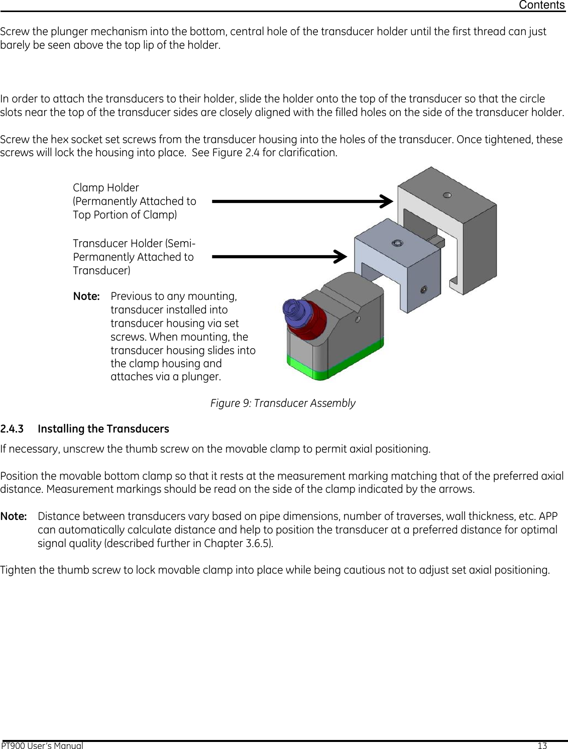
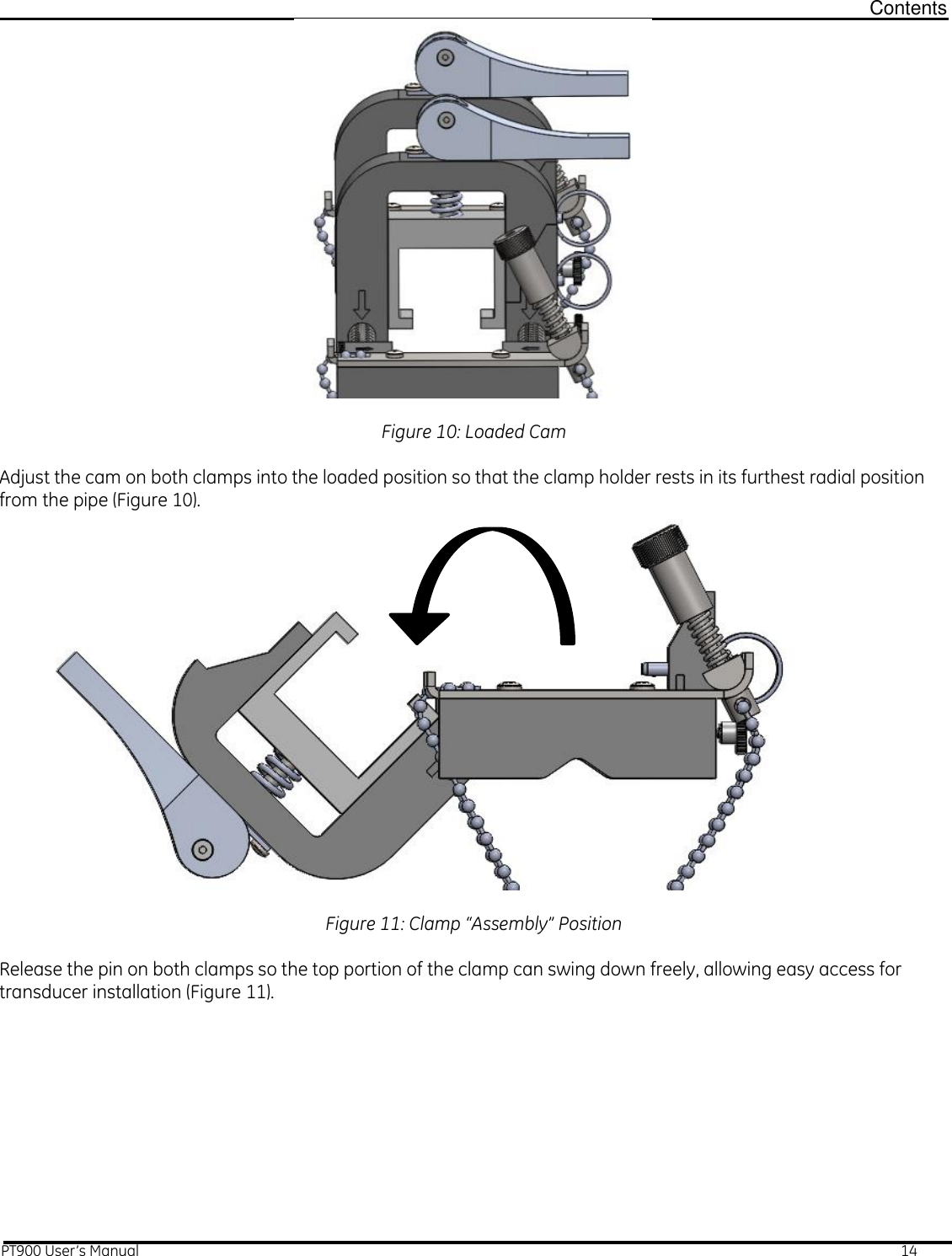
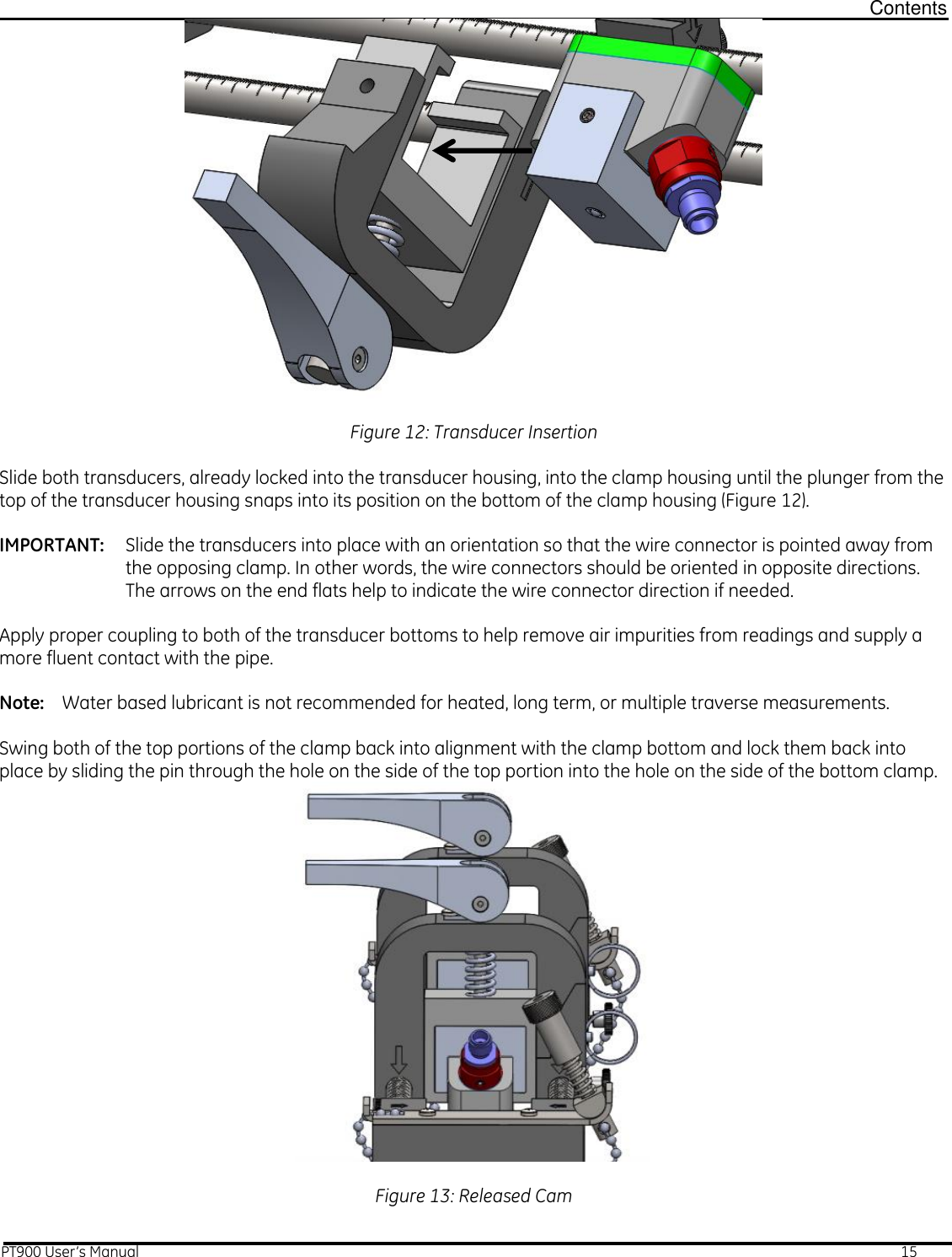
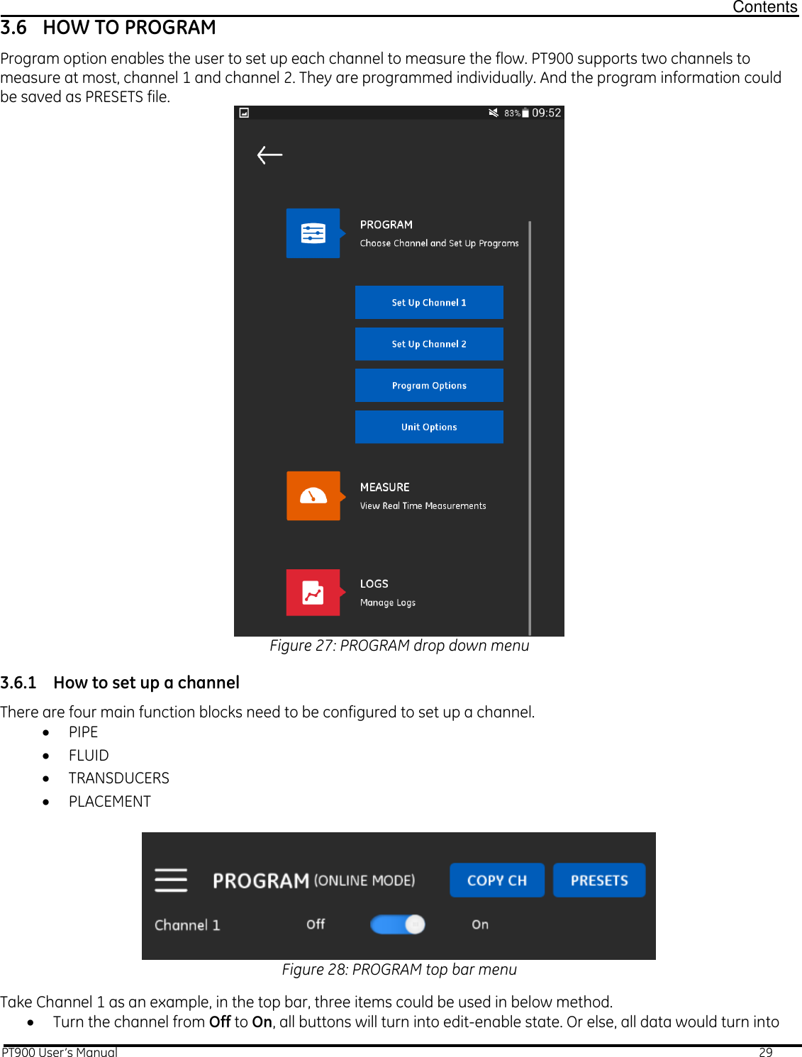
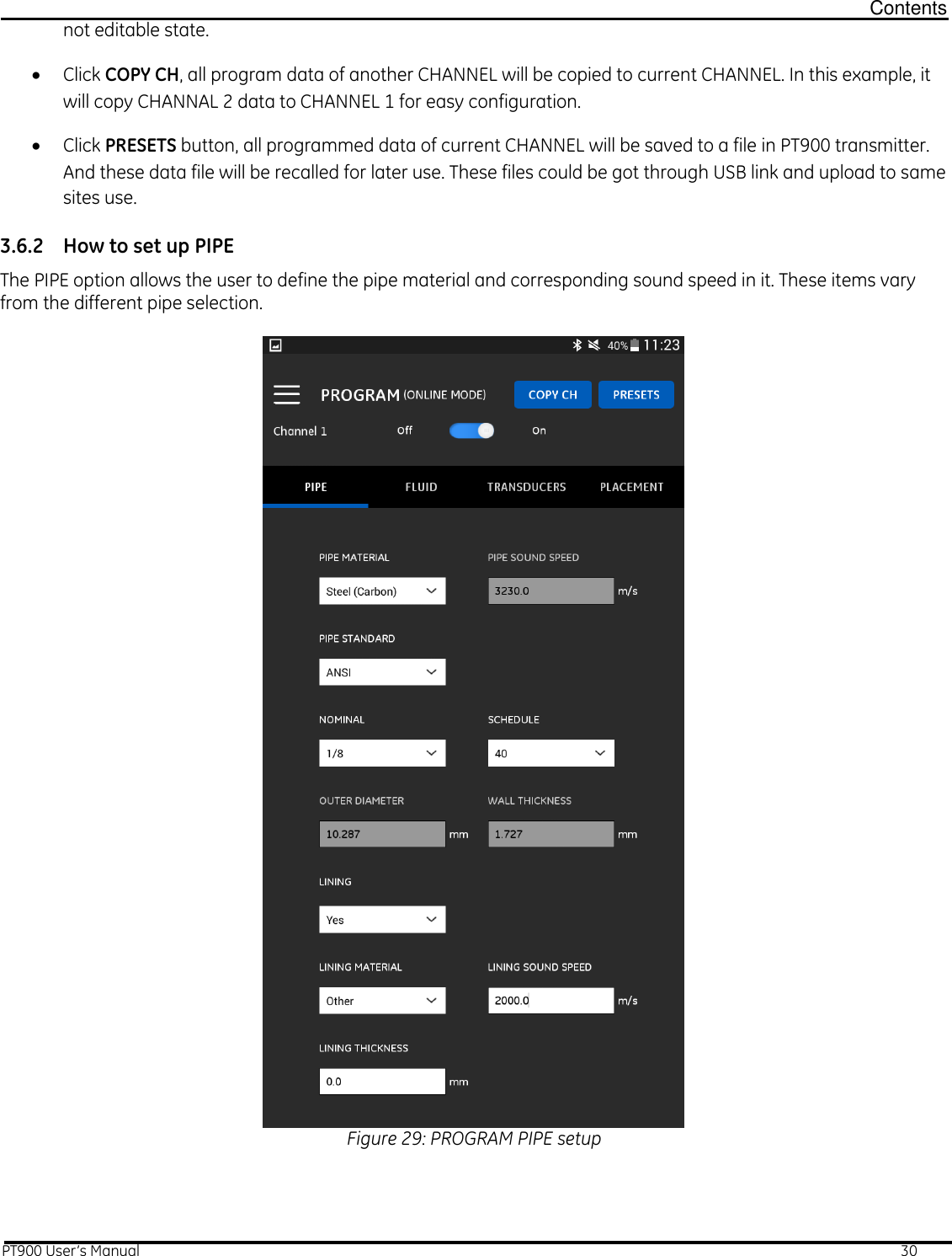
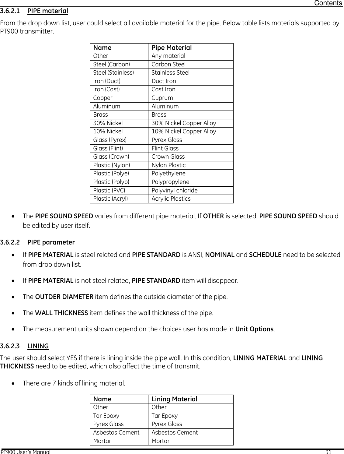
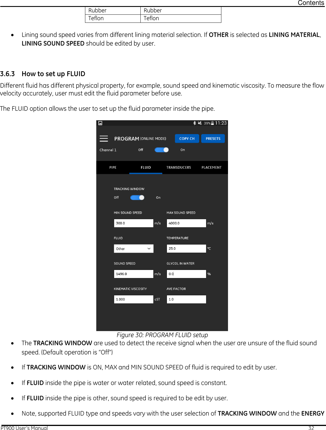
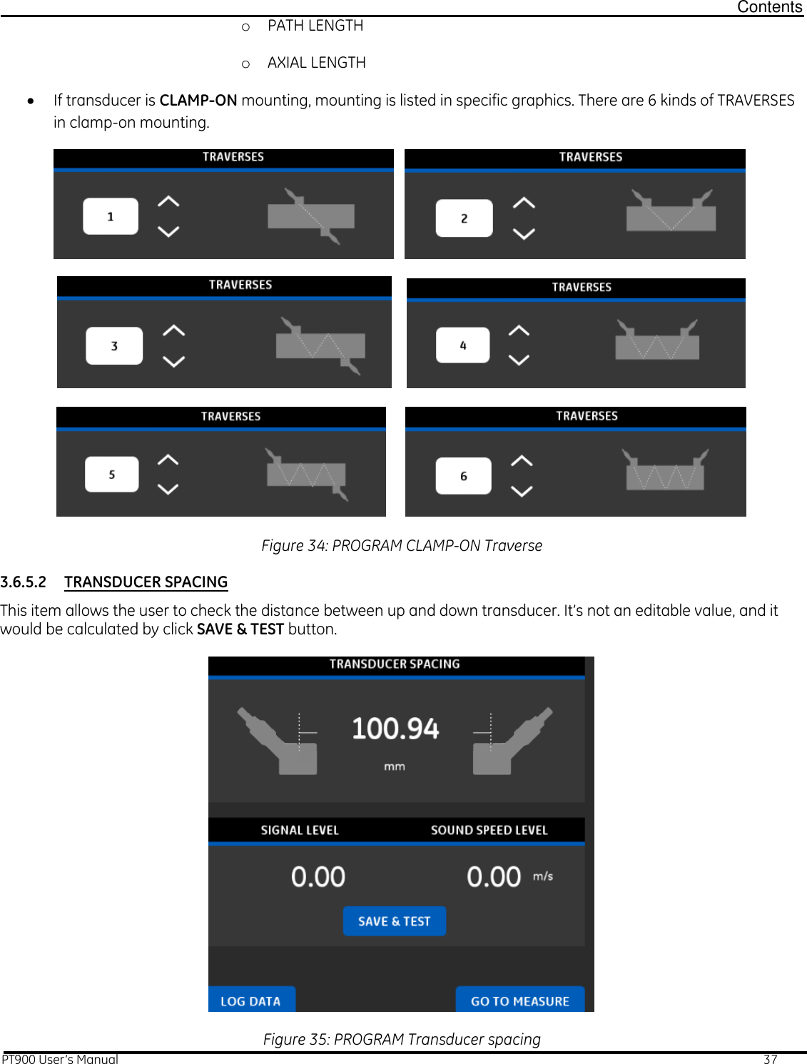
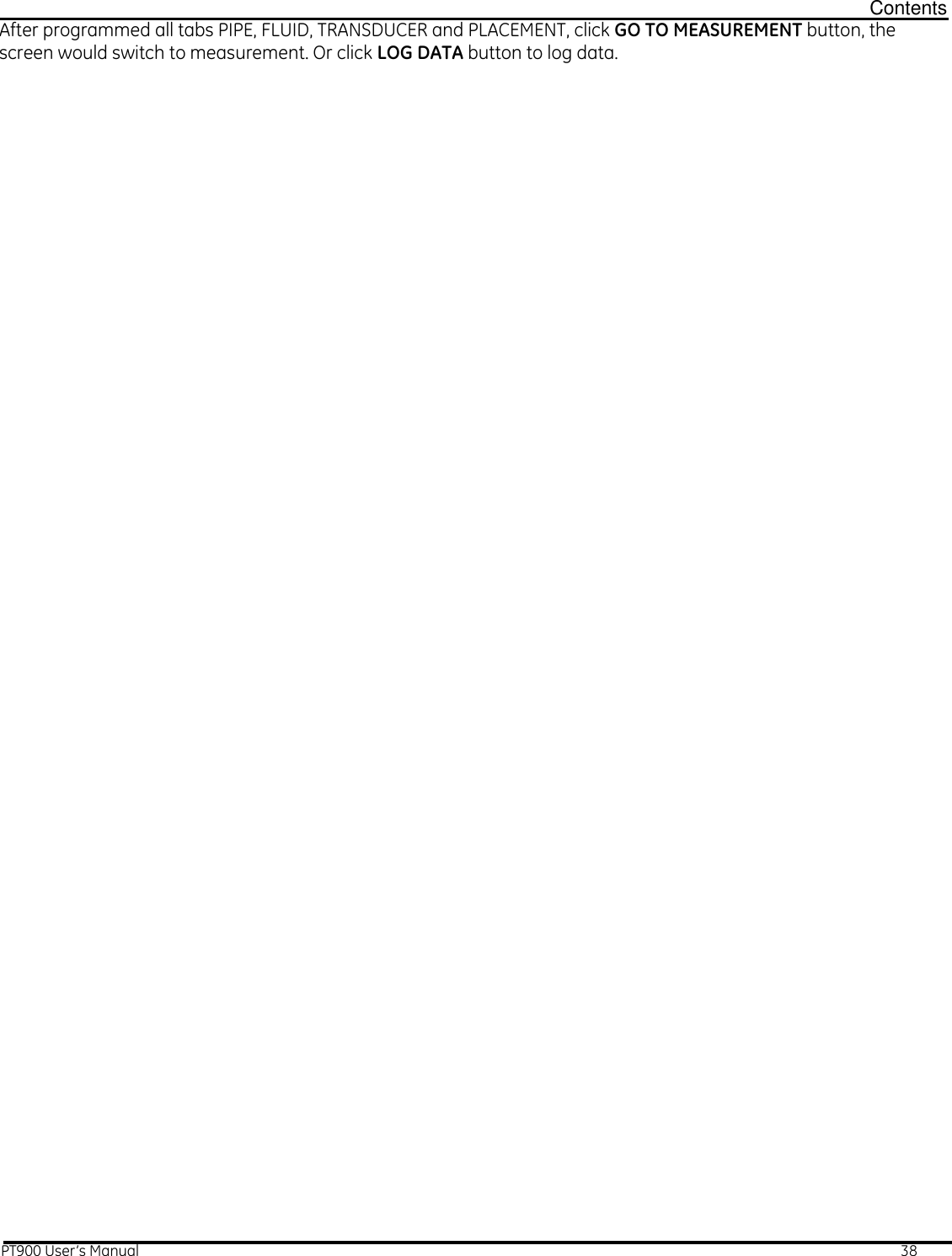
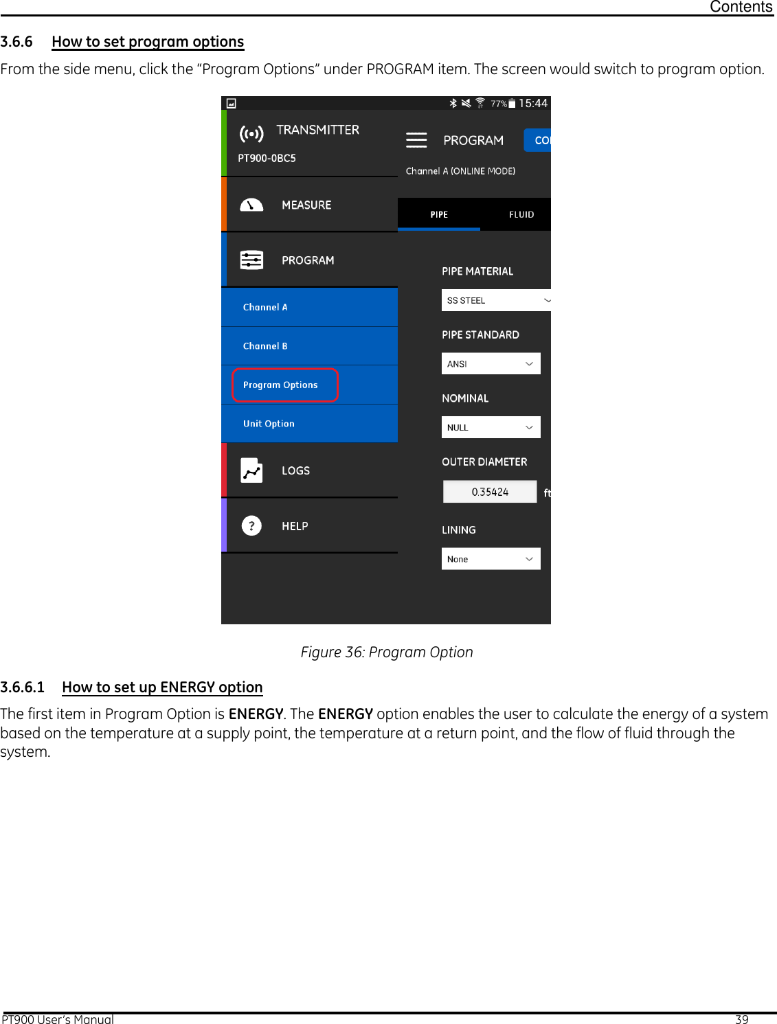
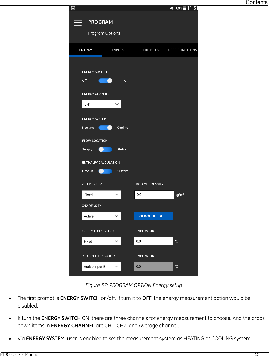
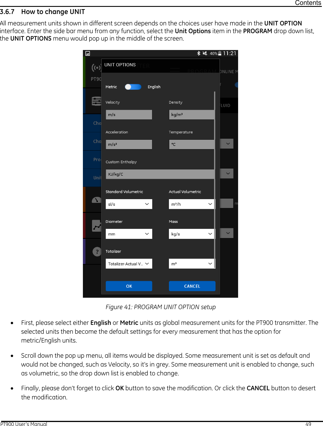
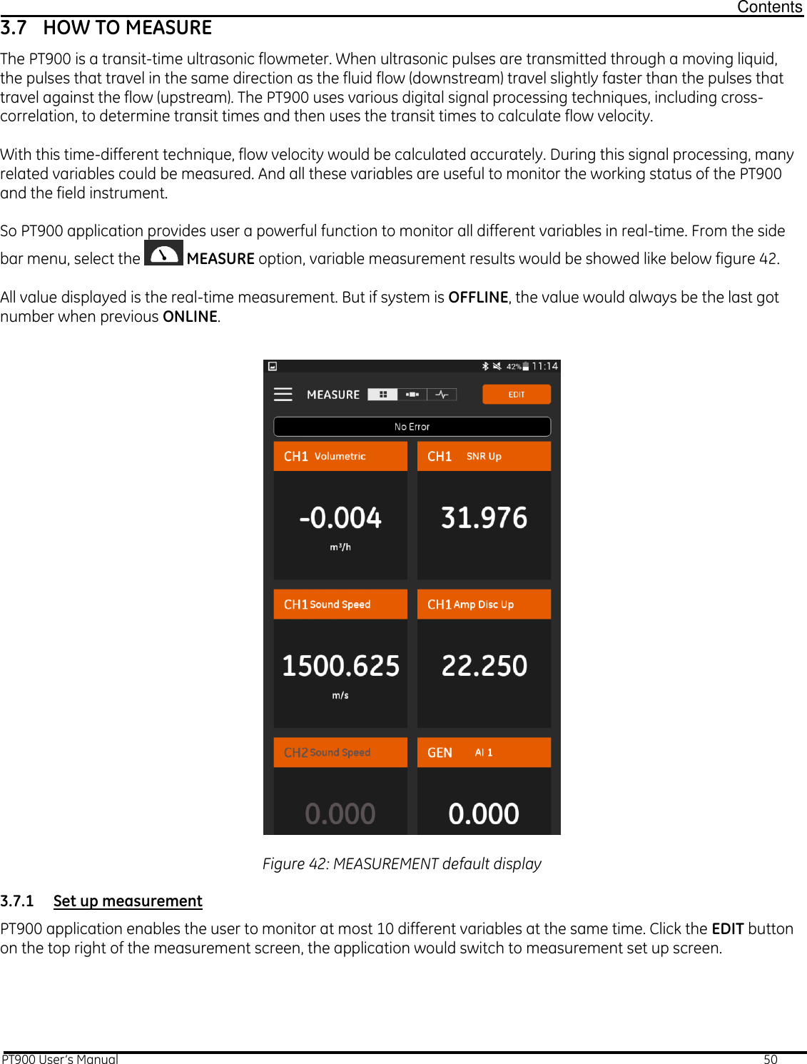
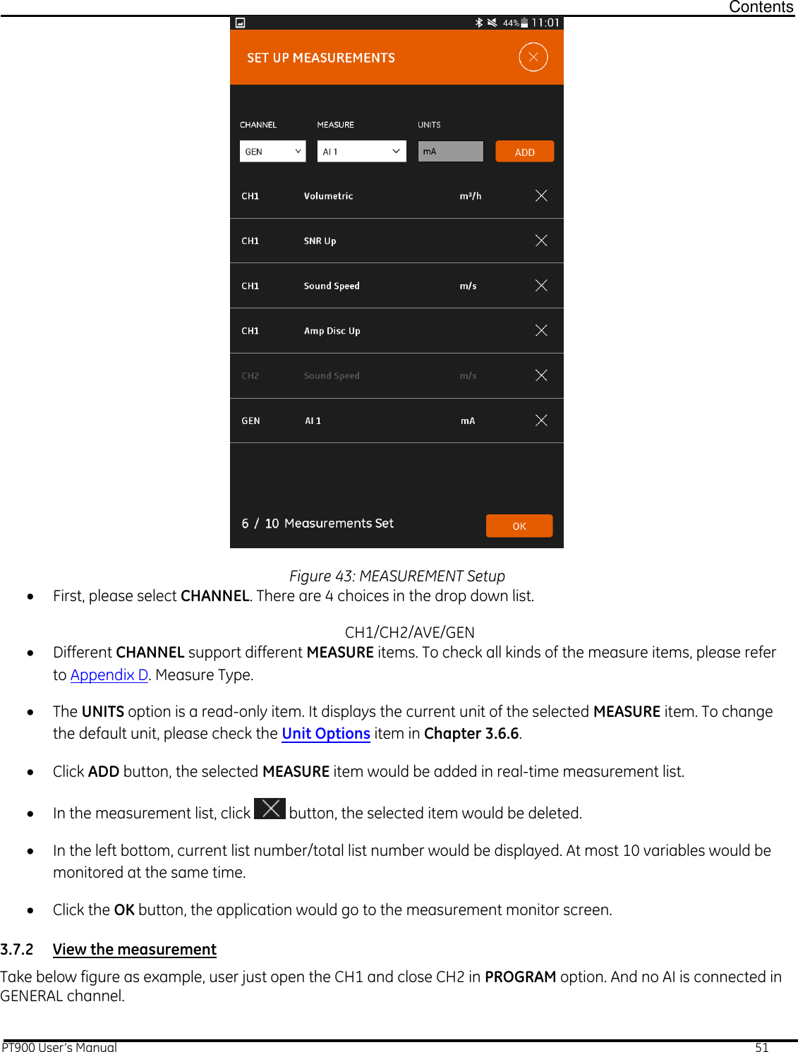
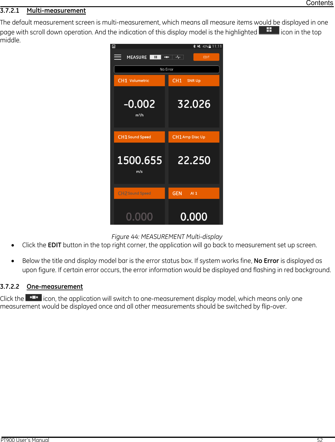
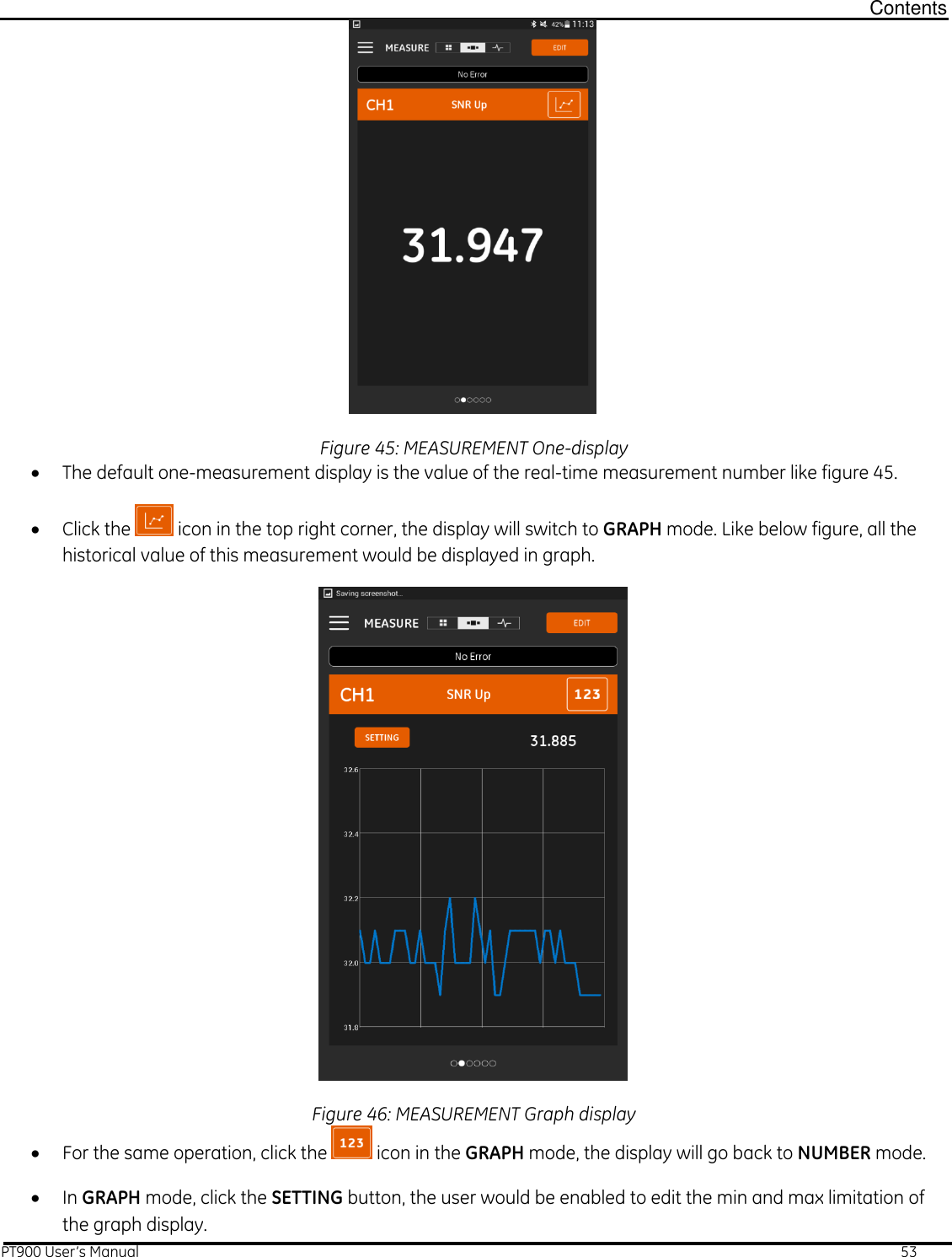
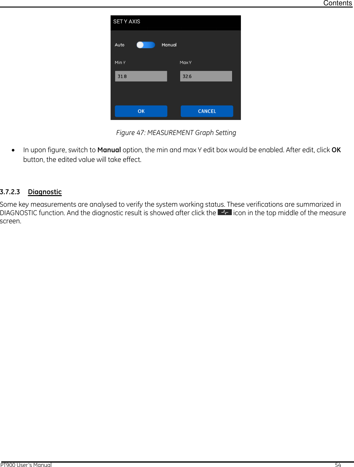
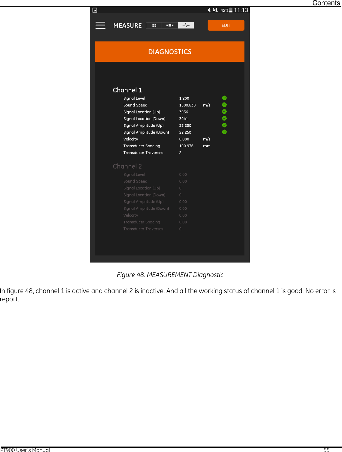
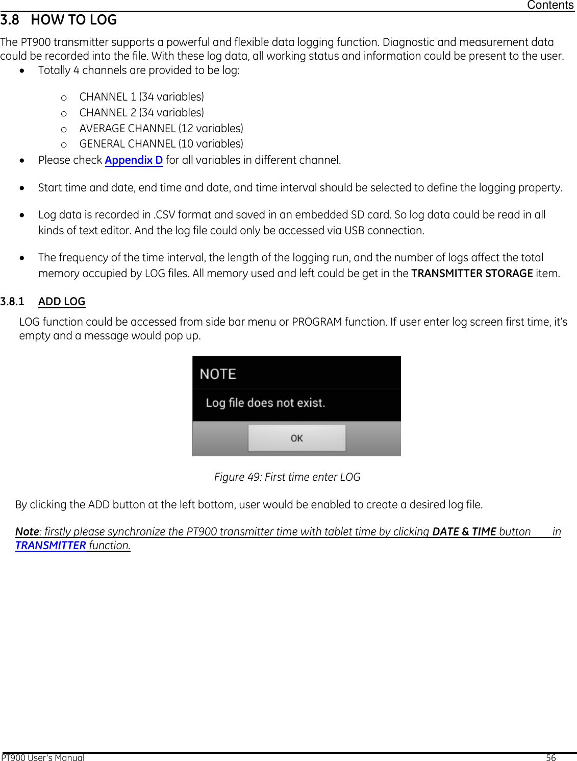
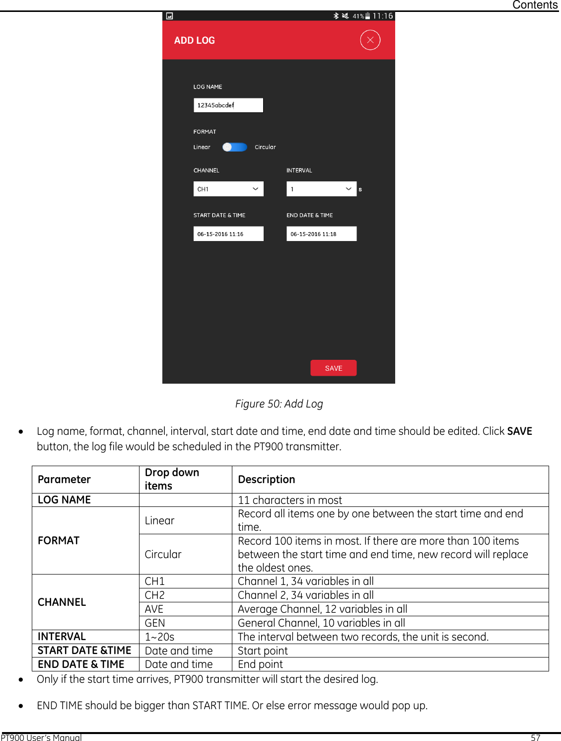
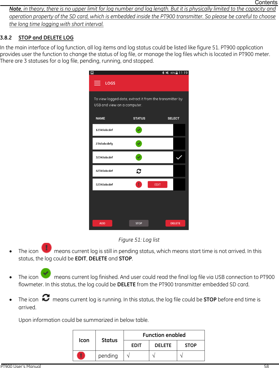
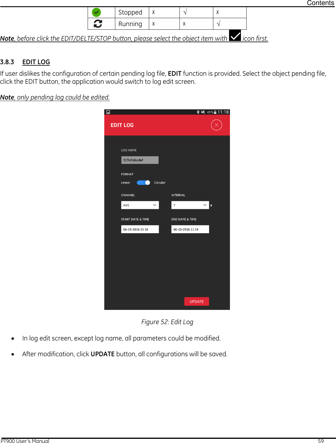
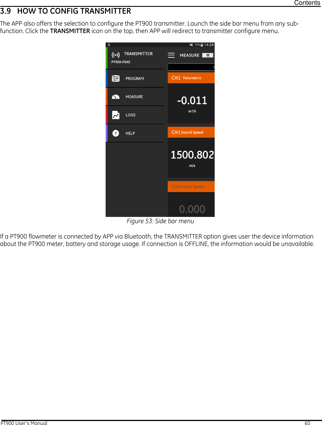
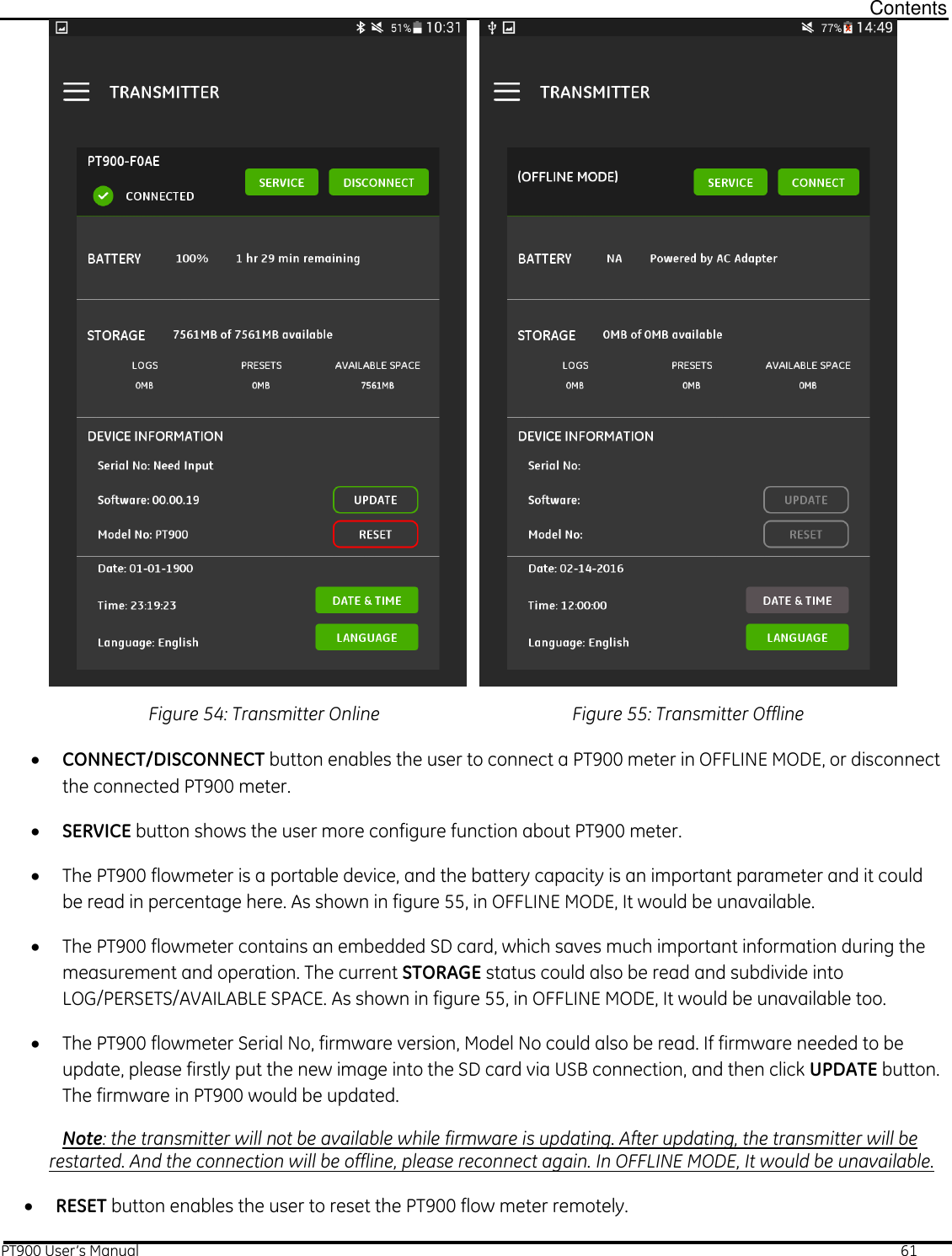
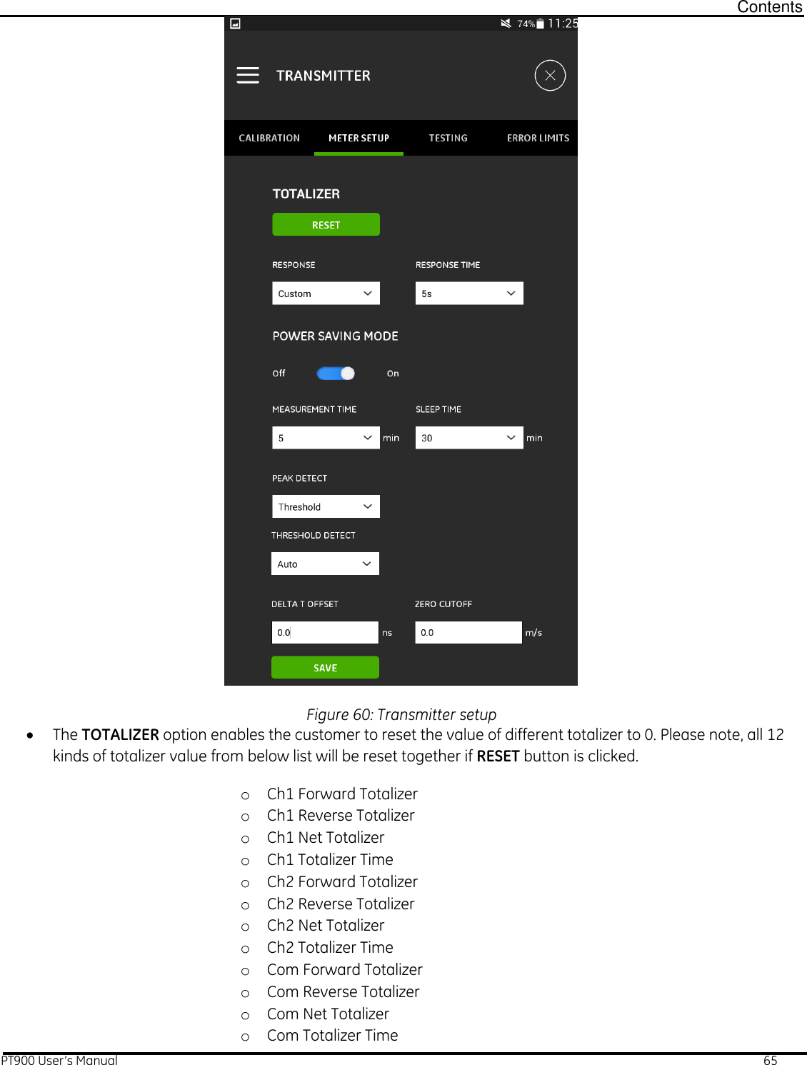
![Contents PT900 User’s Manual 11 2.4 INSTALLING PT900 CLAMP-ON FIXTURE [Include any steps for unboxing and pre-assembly if necessary. Also there needs to be a section in the manual that pertains to batteries, wiring, APP installation and necessary software/hardware platforms for installation purposes. Other sections can be noted in PT878 manual.] 2.4.1 Mounting the Bracket Figure 6: Pre-Assembly Process Before mounting, check that the screw mechanisms (chain mechanism screws) that are pre-attached to the end pieces (end flats) are unscrewed to their full potential [A] and that the last joint in the chain is secured within the chain mechanism screw slot on both sides of the fixture [B]. It is highly recommended that the pin is engaged securing the bottom portion of the clamp mechanism to the top portion [C] and that the thumb screw is tightened on the movable clamp [D] so that no motion is allowed throughout the mounting process. Figure 7: Distance Parameters Adjust the bracket position so that the closest end flat rests at the preferred distance from inlet/outlet/joint/fitting of the pipe. A B C D Flow Direction Fitting Fitting Joint Joint Upstream Downstream >10 Diameters >5 Diameters >6” >6”](https://usermanual.wiki/GE-Sensing-and-Inspection/001/User-Guide-3130692-Page-15.png)
![Contents PT900 User’s Manual 12 IMPORTANT: There must be allotted a straight run of at least 10 diameters (nominal pipe diameters) before the upstream transducer and, preferably, at least 5 diameters after the downstream transducer. A clearance of at least 6in should be provided from the edge of each end flat to the nearest joint/welding/flange. Please see figure 2.2 for clarification. Place the fixture so that minimal effort is required to maintain the fixture position (e.g. even if horizontal positioning is eventually preferred, place the bracket on top of the pipe for mounting). Check that the pipe rests in the small slot cutout on the bottom edge of the end flats. Note: Make sure to mount the bracket with the final orientation in mind so that the markings on the rail rod can be easily read. Figure 8: Chain Connection While holding the end flat closest to the pivotal inlet/outlet/joint/fitting, loop the metal chain around the pipe so that it wraps all the way around. Pull the chain firmly, without compromising the brackets position, and force the chain to slide into the small slot located at the opposite side of the end flat from the chain mechanism screw [E]. Repeat this process for the opposite chain so that the bracket is firmly mounted but has enough leeway to be able to adjust bracket alignments. Adjust the bracket into the preferred orientation on the pipe. Re-center the end flats on the pipe using the small slot cutout on the bottom edge of the end flats as a tangent-to-pipe indicator. (Level may be necessary, depending on accuracy required, to verify that the bracket is aligned down the center of the pipe.) Once aligned, tighten the chains by twisting the nut on top of both chain mechanisms’ screws until the chain is tight enough to resist the bracket’s movement [A, Figure 2.1]. Verify that this extra restraint did not affect the center alignment. If this is the case, loosen the nuts, realign, and tighten the screws until the bracket is aligned and secured tightly. 2.4.2 Installing the Transducers Bracket Before installing the transducers, the transducer holder must be attached to the transducer. In many cases, the transducer holder will already be installed when shipped. If this is the case, skip to section 2.4.3 for installation of the transducers. E End Flat Chain Screw Mechanism](https://usermanual.wiki/GE-Sensing-and-Inspection/001/User-Guide-3130692-Page-16.png)