GE Transportation 84A237140 Gateway User Manual Device PS
GE Transportation Gateway Device PS
User Manual

GE Transportation Systems
RF Gear Case Sensor
6/3/15
Installation Instructions
Rev. A1
Author: David Petersen
Approval: Sethu Madhavan
84A234272AB
Issued: GET Engineering, 6/21/13
BUS. AREA: Loco
Sheet 1 of 31
This Drawing is the Property of GENERAL ELECTRIC COMPANY, TRANSPORTATION SYSTEMS DIVISION. This drawing is loaned upon the express
condition that it shall not be reproduced in any manner, and shall be returned upon demand. It is submitted for evaluation purposes and it, and the information
contained therein, shall not be otherwise used nor disclosed to third parties without written permission of General Electric Co.
DHMS Installation and Programming Instructions
Revision History
Revision
Date
DSRVW
Author
Description of Revision
A
NA
D. Petersen
Added FCC , programming, troubleshooting
updates.
Table of Contents
1.0 INTRODUCTION ........................................................................................................................................... 2
2.0 SENSOR INSTALLATION............................................................................................................................ 6
3.0 SENSOR REMOVAL (When Applicable) ..................................................................................................... 9
4.0 GATEWAY INSTALLATION AND WIRING ........................................................................................... 10
5.0 SENSOR PROGRAMMING & VALIDATION .......................................................................................... 15
6.0 READING OIL LEVELS DURING LOCOMOTIVE MAINTENANCE CYCLES ................................... 16
7.0 UPDATING SENSOR & GATEWAY FIRMWARE ................................................................................... 17
8.0 TROUBLESHOOTING ................................................................................................................................ 24
9.0 DATA LOG DOWNLOAD .......................................................................................................................... 29
APPENDIX A: LOADING DHMS SOFTWARE ON A PC .................................................................................... 30
APPENDIX B: SOFTWARE VERSION CONTROL AND MANAGEMENT ....................................................... 31

GE Transportation Systems
RF Gear Case Sensor
6/3/15
Installation Instructions
Rev. A1
Author: David Petersen
Approval: Sethu Madhavan
84A234272AB
Issued: GET Engineering, 6/21/13
BUS. AREA: Loco
Sheet 2 of 31
This Drawing is the Property of GENERAL ELECTRIC COMPANY, TRANSPORTATION SYSTEMS DIVISION. This drawing is loaned upon the express
condition that it shall not be reproduced in any manner, and shall be returned upon demand. It is submitted for evaluation purposes and it, and the information
contained therein, shall not be otherwise used nor disclosed to third parties without written permission of General Electric Co.
1.0 INTRODUCTION
This document outlines the steps required to install, remove, and program the RF Gear Case Sensor (RGS)
and gateway onto a locomotive. These sensors and gateway are designed to collect and transmit gear case
oil data while in line-haul service.
Follow all shop safety rules when working on or under the locomotive.
FCC Compliance and Notification
GE Part Numbers: 84A237140P1, DHMS Gateway
84A234628P1, RGS Sensor
FCC ID: new number (Pending approval)
These devices comply with part 15 of the FCC Rules. Operation is subject to the following two conditions: (1)
These devices may not cause harmful interference, and (2) these devices must accept any interference
received, including interference that may cause undesired operation.
Changes or modifications to the DHMS Gateway or Sensor are prohibited. Any changes made to these
devises without the written approval by GE Engineering could void the user's authority to operate this
equipment.
Per RSS-Gen, Section 8.4, this device complies with Industry Canada license-exempt RSS standards.
Operation is subject to the following two conditions: (1) this device may not cause interference, and (2) this
device must accept any interference, including interference that may cause undesired operation of the device
--------------------------------------------------------------------------
Par RSS-Gen, la section 8.4, cet appareil est conforme aux normes Industrie Canada RSS exemptes de
licence. Son fonctionnement est soumis aux deux conditions suivantes: (1) ce dispositif ne peut pas
provoquer d'interférences et (2) cet appareil doit accepter toute interférence, y compris les interférences qui
peuvent causer un mauvais fonctionnement de l'appareil.
Les modifications apportées à la passerelle DHMS ou le capteur sont interdits. Les modifications apportées à
ces dispositifs sans l'approbation écrite par GE Ingénierie pourraient annuler l'autorité de l'utilisateur à utiliser
cet équipement.
1.1 Acronyms
BS Battery Switch
DHMS Drive Train Health Monitoring System
FCC US Federal Communications Commission
GE General Electrical
MBS Maintenance Battery Switch
RGS RF Gear Case Sensor

GE Transportation Systems
RF Gear Case Sensor
6/3/15
Installation Instructions
Rev. A1
Author: David Petersen
Approval: Sethu Madhavan
84A234272AB
Issued: GET Engineering, 6/21/13
BUS. AREA: Loco
Sheet 3 of 31
This Drawing is the Property of GENERAL ELECTRIC COMPANY, TRANSPORTATION SYSTEMS DIVISION. This drawing is loaned upon the express
condition that it shall not be reproduced in any manner, and shall be returned upon demand. It is submitted for evaluation purposes and it, and the information
contained therein, shall not be otherwise used nor disclosed to third parties without written permission of General Electric Co.
RSS Canadian Radio Standards Specification

GE Transportation Systems
RF Gear Case Sensor
6/3/15
Installation Instructions
Rev. A1
Author: David Petersen
Approval: Sethu Madhavan
84A234272AB
Issued: GET Engineering, 6/21/13
BUS. AREA: Loco
Sheet 4 of 31
This Drawing is the Property of GENERAL ELECTRIC COMPANY, TRANSPORTATION SYSTEMS DIVISION. This drawing is loaned upon the express
condition that it shall not be reproduced in any manner, and shall be returned upon demand. It is submitted for evaluation purposes and it, and the information
contained therein, shall not be otherwise used nor disclosed to third parties without written permission of General Electric Co.
1.2 Bill of Material
The following material is an example of the 84A237221G1 Kit
Item
Identification
Description
QTY
1
84A234628P2
SENSOR ASSEM KIT
6
84A234628G1
SENSOR ASSEM
1
84B547003P1
NPI BASE (Norca)
1
N22P21022B13
BOLT .25-20 X 1.38
6
N402P11B13
WASHER, 1/4 FLAT
6
2
84A237140P1
HDMS GATEWAY
1
3
84A237140P2
ANTENNA, 2.4 GHZ
1
4
84A237140P3
COAX CABLE, 3 FT
1
5
84A233729BAP153
ETHERNET CABLE, 10 FT
1
6
84A210299ALG4
WIRE HARNESS, POWER
1
7
84B550946G1
BRACKET, DHMS AC4400
1
8
84D641291G1
BRACKET, DHMS EVO
1
9
N210P15B13
NUT, 8-32
4
10
N402P8B13
WASHER, #8 FLAT
4
11
N405P38B13
WASHER, #8 LOCK
4
12
41A212852P8
RIVETS, POP 1/8 DIA
4
13
N743P1712B13
SCREW, #10 x .75 SELF TAPPING
8
14
499A910ACP9
P-CLIPS
4
15
84A207604AFP1
LABEL, DHMS
1
16
41A252287P2
TIE WRAPS, 14"
18
17
84A237336P1
LABEL, DHMS ANTENNA
1
18
84A234272AB
INSTALLATION INSTRUCTIONS
X
19
41B587212G1
TOOL, INSTALLATION
AR
Note: Kit items 18 and 19 are not included within the kit. These are reference items only.

GE Transportation Systems
RF Gear Case Sensor
6/3/15
Installation Instructions
Rev. A1
Author: David Petersen
Approval: Sethu Madhavan
84A234272AB
Issued: GET Engineering, 6/21/13
BUS. AREA: Loco
Sheet 5 of 31
This Drawing is the Property of GENERAL ELECTRIC COMPANY, TRANSPORTATION SYSTEMS DIVISION. This drawing is loaned upon the express
condition that it shall not be reproduced in any manner, and shall be returned upon demand. It is submitted for evaluation purposes and it, and the information
contained therein, shall not be otherwise used nor disclosed to third parties without written permission of General Electric Co.
1.3 Tools & Equipment Required:
1.3.1 Tools and Equipment for Sensor Installation
Wire Cutters
Pipe wrench, 18” handle
RGS Flange Tool 41B587212G1
Torque Wrench, ½” drive (150 ft-lbs. capacity)
Torque Wrench, 3/8” drive (150 in-lbs. capacity)
15/16” socket, ½” drive
7/16” socket, 3/8” drive
Safety Wire Pliers (Sensor Removal Only)
Indirect Material
497A806P118 RTV (DOW 832)
497A806P87 Hylomar Advanced
1.3.2 Tools and Equipment for Gateway Installation
Wire Cutters
Terminal Crip Tool
½” capacity Drill
#30 (.128”) or .125” Drill Bit
3/32” Drill Bit
7/16” Drill Bit
Pop rivet tool.
1.3.3 Reference Drawings
RGS Sensor Outline 84B546999
DHMS Gateway 84C641274
GE Transportation Systems
RF Gear Case Sensor
6/3/15
Installation Instructions
Rev. A1
Author: David Petersen
Approval: Sethu Madhavan
84A234272AB
Issued: GET Engineering, 6/21/13
BUS. AREA: Loco
Sheet 6 of 31
This Drawing is the Property of GENERAL ELECTRIC COMPANY, TRANSPORTATION SYSTEMS DIVISION. This drawing is loaned upon the express
condition that it shall not be reproduced in any manner, and shall be returned upon demand. It is submitted for evaluation purposes and it, and the information
contained therein, shall not be otherwise used nor disclosed to third parties without written permission of General Electric Co.
2.0 SENSOR INSTALLATION
2.1 Place the locomotive over a service pit. Apply the hand brake. Follow safety rules for working under a
locomotive. Blue flag the track as required by local shop policy.
2.2 Cut the safety wire securing the 1-1/4” oil-fill pipe plug to the end of the gear case.
2.3 Check the oil level in the gear case; adjust as needed. Record the oil level per shop procedures.
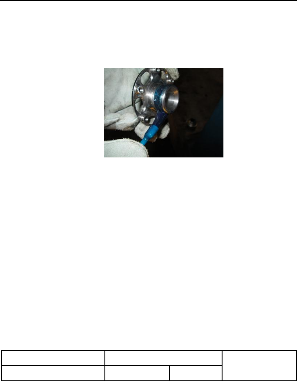
2.4 Apply Hylomar thread sealant to the pipe threads of the RGS’s NPT adapter per Figure 2.1.
Figure 2.1: Hylomar Sealant Application
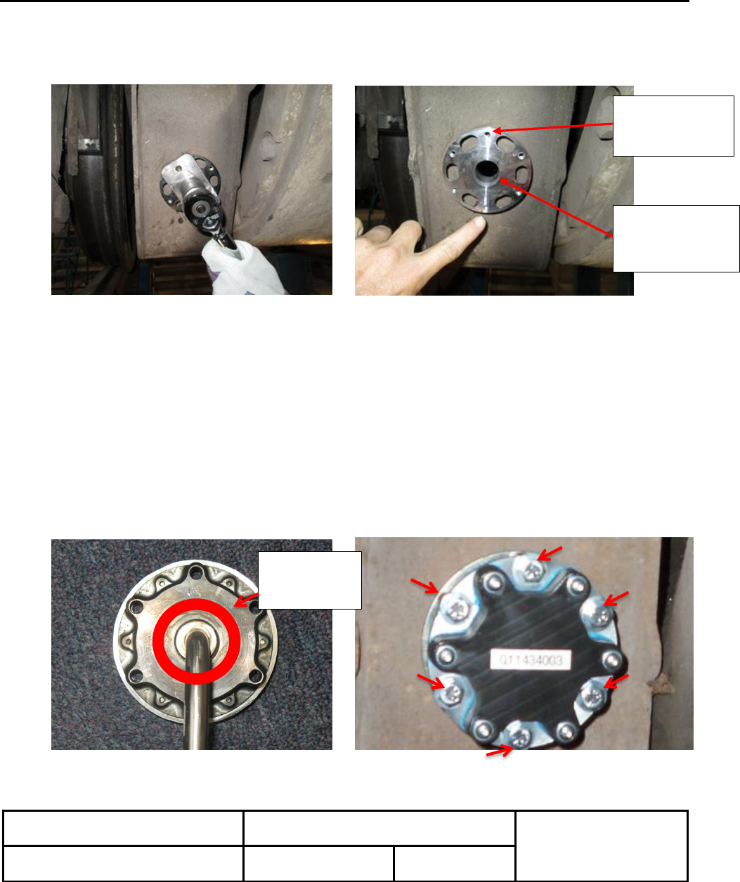
2.5 Install the NPT adapter to gear case. Torque the fitting to 100 ft-lbs using tool 41B587212G1 (Figure
2.2). Note the location of the six (6) ¼” mounting hole around the outside of the flange. Continue to
GE Transportation Systems
RF Gear Case Sensor
6/3/15
Installation Instructions
Rev. A1
Author: David Petersen
Approval: Sethu Madhavan
84A234272AB
Issued: GET Engineering, 6/21/13
BUS. AREA: Loco
Sheet 7 of 31
This Drawing is the Property of GENERAL ELECTRIC COMPANY, TRANSPORTATION SYSTEMS DIVISION. This drawing is loaned upon the express
condition that it shall not be reproduced in any manner, and shall be returned upon demand. It is submitted for evaluation purposes and it, and the information
contained therein, shall not be otherwise used nor disclosed to third parties without written permission of General Electric Co.
tighten the NPT adapter until 1 hole is in the 12 o’clock position (Figure 2.3). DO NOT loosen the fitting to
align the hole.
Figure 2.2: NPT Flange Installation Figure 2.3: NPT Flange Alignment
2.6 Wipe a small amount of oil onto the inside diameter of the NPT flange to help seat the O-ring (Figure 2.3).
2.7 NOTE: Sensors maybe pre-programmed and marked by position by the manufacturer. Ensure each
sensor is applied to the corresponding traction motor. Traction Motors are numbered 1-6 from the front of
the locomotive to the rear.
2.8 Apply a small amount of RTV (DOW 832, GE 497A806P118) sealant to the sensor flange between the
bolt holes and center boss per Figure 2.4.
2.9 Install the sensor housing onto the NPT adapter flange. The oil sensor (candy cane) should face
downward into the oil. Slightly twist the sensor into position to seat the flanges. Use caution not to
damage the O-ring.
2.10 Apply Locktite 242 compound to the six (6) ¼-20 mounting screws and install. Torque the hardware to
78 in-lbs. See Figure 2.5.
Figure 2.4: RTV Location Figure 2.5: Sensor Bolts Installation
Wipe oil inside
hole to help seat
O-ring.
Align ¼” holes at
6 & 12 O-clock
positions.
Apply RTV
on Sensor
Base

GE Transportation Systems
RF Gear Case Sensor
6/3/15
Installation Instructions
Rev. A1
Author: David Petersen
Approval: Sethu Madhavan
84A234272AB
Issued: GET Engineering, 6/21/13
BUS. AREA: Loco
Sheet 8 of 31
This Drawing is the Property of GENERAL ELECTRIC COMPANY, TRANSPORTATION SYSTEMS DIVISION. This drawing is loaned upon the express
condition that it shall not be reproduced in any manner, and shall be returned upon demand. It is submitted for evaluation purposes and it, and the information
contained therein, shall not be otherwise used nor disclosed to third parties without written permission of General Electric Co.
2.11 Follow tasks 2-10 for the remaining sensors until all 6 Traction Motors are equipped.
2.12 Record the Sensor’s ID number (9 digit Serial Number located on face of sensor), by axle position, and
enter this information into the corresponding eservices work scope tasks under FTON-26-42292.
Road Number: ___________
Axle Number 1: Sensor ID: ________________________________
Axle Number 2: Sensor ID: ________________________________
Axle Number 3: Sensor ID: ________________________________
Axle Number 4: Sensor ID: ________________________________
Axle Number 5: Sensor ID: ________________________________
Axle Number 6: Sensor ID: ________________________________

GE Transportation Systems
RF Gear Case Sensor
6/3/15
Installation Instructions
Rev. A1
Author: David Petersen
Approval: Sethu Madhavan
84A234272AB
Issued: GET Engineering, 6/21/13
BUS. AREA: Loco
Sheet 9 of 31
This Drawing is the Property of GENERAL ELECTRIC COMPANY, TRANSPORTATION SYSTEMS DIVISION. This drawing is loaned upon the express
condition that it shall not be reproduced in any manner, and shall be returned upon demand. It is submitted for evaluation purposes and it, and the information
contained therein, shall not be otherwise used nor disclosed to third parties without written permission of General Electric Co.
3.0 SENSOR REMOVAL (When Applicable)
3.1 Place the locomotive over a service pit.
3.2 Remove the 1/4” bolts (Quantity 6) holding the sensor to the gear case NPT adapter.
3.3 Remove the sensor from the NPT adapter by gently prying with a screwdriver and the base on the flange.
3.4 If applying a new sensor, follow Section 2.0, Sensor Installation.
3.5 If not applying a new RGS sensor, continue to remove the NPT adapter using tool 41B587212G1.
3.6 Apply thread sealant to the 1-1/4” NPT pipe plug.
3.7 Torque the Pipe Plug to 105 ft-lbs.
3.8 Apply Safety-wire the plug to the gear case to prevent loosening.

GE Transportation Systems
RF Gear Case Sensor
6/3/15
Installation Instructions
Rev. A1
Author: David Petersen
Approval: Sethu Madhavan
84A234272AB
Issued: GET Engineering, 6/21/13
BUS. AREA: Loco
Sheet 10 of 31
This Drawing is the Property of GENERAL ELECTRIC COMPANY, TRANSPORTATION SYSTEMS DIVISION. This drawing is loaned upon the express
condition that it shall not be reproduced in any manner, and shall be returned upon demand. It is submitted for evaluation purposes and it, and the information
contained therein, shall not be otherwise used nor disclosed to third parties without written permission of General Electric Co.
4.0 GATEWAY INSTALLATION AND WIRING
4.1 Shut down the main engine.
4.2 Open all CB’s on the EC panel.
4.3 Open the BS switch.
4.4 Open the MBS switch (if equipped).
4.5 Open the CA1 locker doors.
4.6 Locate the two Gateway mounting brackets. One is for EVO model locomotives and the other is for
AC4400 model locomotives.
Figure 4.1: Gateway Mounting Brackets
4.7 NOTE: For EVO model locomotives follow steps 4.8 to 4.13. For AC4400 locomotives, skip to step
4.14.
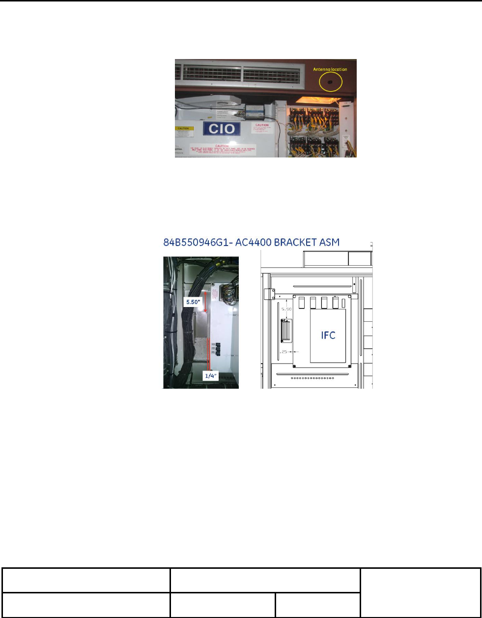
4.8 For EVO models, locate bracket on the CA1 wall above the CIO panel. The hole pattern for the rivets
has been offset for easier installation. Orient the bracket per Figure 4.2.
Figure 4.2: Bracket Mounting, EVO
4.9 Mark the 4 rivet mounting holes using the bracket PN 84C641291G1 as a template.
4.10 Drill four .128” holes in the CA1 wall.
Offset Hole
GE Transportation Systems
RF Gear Case Sensor
6/3/15
Installation Instructions
Rev. A1
Author: David Petersen
Approval: Sethu Madhavan
84A234272AB
Issued: GET Engineering, 6/21/13
BUS. AREA: Loco
Sheet 11 of 31
This Drawing is the Property of GENERAL ELECTRIC COMPANY, TRANSPORTATION SYSTEMS DIVISION. This drawing is loaned upon the express
condition that it shall not be reproduced in any manner, and shall be returned upon demand. It is submitted for evaluation purposes and it, and the information
contained therein, shall not be otherwise used nor disclosed to third parties without written permission of General Electric Co.
4.11 Mount the bracket to the CA1 wall using the 1/8” pop rivets provided.
4.12 Drill a 15/32” hole above the single CA1 locker door in center of the light box, about 2” above the door
opening. See Figure 4.3.
Figure 4.3: Antenna Location –EVO
4.13 Mount the Antenna in the 15/32” hole using the provided nut. The cable should be inside CA1.
4.14 For AC4400 models, locate bracket on the CA1 wall next to the IFC panel. The flat side of the bracket
should face the tape rail and harness. Rotate the harness towards the A-side of the locomotive if
required to free up more space. See Figure 4.4.
Figure 4.4: Bracket Mounting AC4400
4.15 Mark the 4 mounting holes using the bracket PN 84B550946G1as a template.
4.16 Drill four .128” holes in the CA1 wall.
4.17 Mount the bracket to the CA1 wall using the 1/8” pop rivets provided.
4.18 Drill a 15/32” hole above the single CA1 locker door in the center of the upper door rail. . Locate the
hole in center of the door flange. Verify there is no wiring behind the flange before drilling. See Figure
4.5.
GE Transportation Systems
RF Gear Case Sensor
6/3/15
Installation Instructions
Rev. A1
Author: David Petersen
Approval: Sethu Madhavan
84A234272AB
Issued: GET Engineering, 6/21/13
BUS. AREA: Loco
Sheet 12 of 31
This Drawing is the Property of GENERAL ELECTRIC COMPANY, TRANSPORTATION SYSTEMS DIVISION. This drawing is loaned upon the express
condition that it shall not be reproduced in any manner, and shall be returned upon demand. It is submitted for evaluation purposes and it, and the information
contained therein, shall not be otherwise used nor disclosed to third parties without written permission of General Electric Co.
Figure 4.5: Antenna Location, AC4400
4.19 Mount the Antenna in the 15/32” hole using the provided nut. The cable should be inside CA1.
4.20 EVOS and AC4000s: Add the device labels (item 15, 84A207604AFP1) near the gateway and around
the antenna cable inside CA1.
4.21 Add the label, “DHMS ANTENNA” (item 17, 84A237336P1) next to the antenna, above the CA1door.
4.22 Attach the 3 foot coax cable to the Gateway’s ANT port. Use caution not to bend the center conductor.
4.23 Attach the other end of the coax cable to the Antenna.
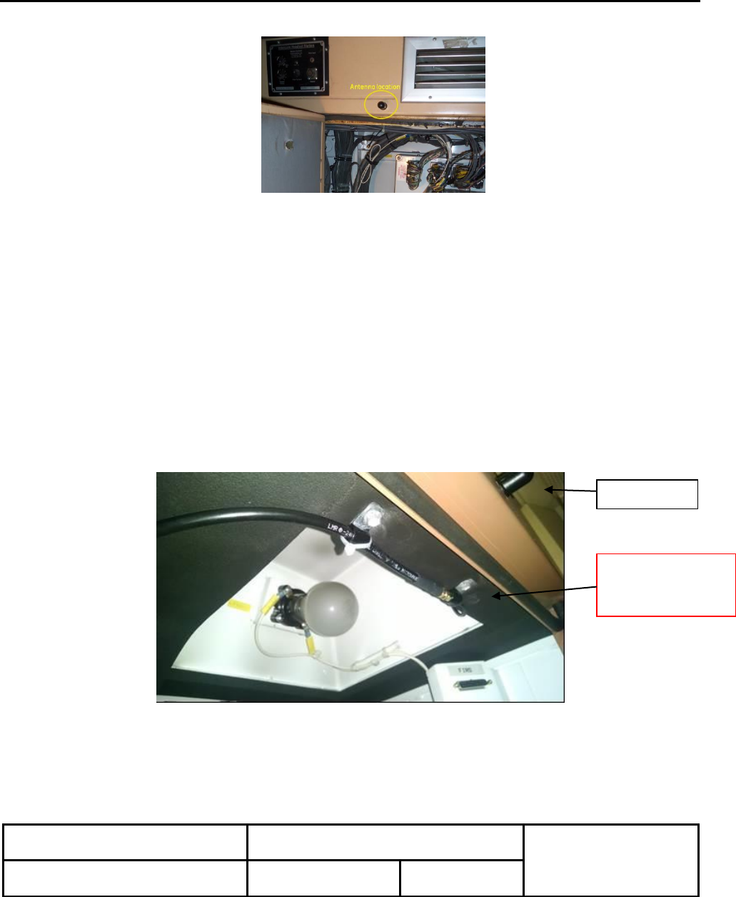
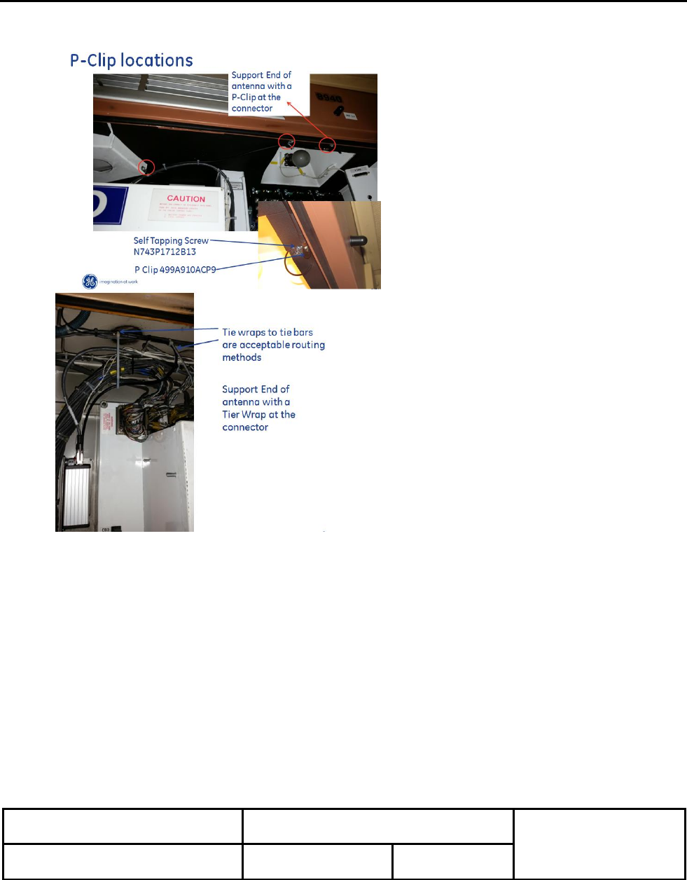
4.24 CRITICALLY STEP: Add Quantity 4 P-Clips and Self Tapping Screws to support coax cable. One P-
Clip should support the connection between coax cable and antenna cable (Figure 4.6). Add the other
P-clips as needed to support the coax and wiring at maximum 12 inches per Figures 4.7 and/or 4.8.
Figure 4.6: Antenna Cable P-clip and Coax Support
Antenna
Antenna & Coax
Connection
With P-Clip
GE Transportation Systems
RF Gear Case Sensor
6/3/15
Installation Instructions
Rev. A1
Author: David Petersen
Approval: Sethu Madhavan
84A234272AB
Issued: GET Engineering, 6/21/13
BUS. AREA: Loco
Sheet 13 of 31
This Drawing is the Property of GENERAL ELECTRIC COMPANY, TRANSPORTATION SYSTEMS DIVISION. This drawing is loaned upon the express
condition that it shall not be reproduced in any manner, and shall be returned upon demand. It is submitted for evaluation purposes and it, and the information
contained therein, shall not be otherwise used nor disclosed to third parties without written permission of General Electric Co.
Figure 4.7: P-clips (EVO) Figure 4.8: Tape Rails (AC4400)
4.25 The DHMS wiring diagram is shown in Figure 4.9. Remove connector “ROOFTOP POWER” from the
CMU and open the back-shell.
4.26 Insert wire DHMSP with the end RTPRW 3 into pin 3 of the connector (+15 VDC).
4.27 Insert wire DHMSN with the end RTPWR 9 into pin 9 of the connector (-15 VDC).
4.28 Re-install the CMU connector after assembling the back-shell.
4.29 Route wire DHMSP to the Gateway and connect the ring terminal to the Gateway’s 10-30 VDC +
terminal post.
4.30 Route wire DHMSN to the Gateway and connect the ring terminal to the Gateway’s 10-30 VDC -
terminal post.
4.31 Connect the Ethernet cable to CMU connector ENET02 and tighten connector.
4.32 Route the Ethernet cable to the Gateway and connector to the ETHERNET port.

GE Transportation Systems
RF Gear Case Sensor
6/3/15
Installation Instructions
Rev. A1
Author: David Petersen
Approval: Sethu Madhavan
84A234272AB
Issued: GET Engineering, 6/21/13
BUS. AREA: Loco
Sheet 14 of 31
This Drawing is the Property of GENERAL ELECTRIC COMPANY, TRANSPORTATION SYSTEMS DIVISION. This drawing is loaned upon the express
condition that it shall not be reproduced in any manner, and shall be returned upon demand. It is submitted for evaluation purposes and it, and the information
contained therein, shall not be otherwise used nor disclosed to third parties without written permission of General Electric Co.
4.33 Verify all the connections are tight and dress the wires with the tie wraps provided to prevent excess
vibration.
4.34 Close the MBS, BS, and CBs.
4.35 Verify there is power to the CMU. It’s LED’s should be on.
4.36 Verify there is power to the Gateway. The “POWER” LED and “LINK” LED should be on.
4.37 Proceed to the Programming and Test sections of this document.
Figure 4.9: DHMS Wiring Diagram

GE Transportation Systems
RF Gear Case Sensor
6/3/15
Installation Instructions
Rev. A1
Author: David Petersen
Approval: Sethu Madhavan
84A234272AB
Issued: GET Engineering, 6/21/13
BUS. AREA: Loco
Sheet 15 of 31
This Drawing is the Property of GENERAL ELECTRIC COMPANY, TRANSPORTATION SYSTEMS DIVISION. This drawing is loaned upon the express
condition that it shall not be reproduced in any manner, and shall be returned upon demand. It is submitted for evaluation purposes and it, and the information
contained therein, shall not be otherwise used nor disclosed to third parties without written permission of General Electric Co.
5.0 SENSOR PROGRAMMING & VALIDATION
This section outlines the steps required to program the RF Gear Case Sensor (RGS) on the locomotive with
the Customer ID, Road Number, and Axle Position during initial installation or combo change-out.
Use this method when validating the Gateway’s communication to the CMU. Once the communications is
established through the Ethernet port, the RGS sensors ID’s, road number, or axle position can be
programmed.
Note: The CMU must be powered on, however the CMU’s internal software isn’t used for this test.
Future programming, once the Ethernet link is validated, can be done through the USB connection.
Note: For PC laptop users, see Appendix A for loading the Application software and setting to IP address
Programming the Gateway though the CMU:
5.1 On the loco, open the CA1 door to access the Gateway and CMU. Take the yellow CMU download
cable and plug it into CMU port E-NET 03 and your PC USB port. (The cable from the Gateway should
stay connected to CMU at port E-NET 02.)
5.2 Open the “DHMS Gateway Configuration Manager” software from the desk top. Select the “Network”
radio button at the top of the page.
5.3 Verify the “Host Address” is 10.10.9.252 and the “Tcp Port” to 10001.
Note: The first 4 gateways use an IP address of 128.0.0.30 and the “Tcp Port” to 10002. These will be
upgraded in the near future to the new address. Use the USB port to connect to these units.
5.4 Select “Open Gateway Connection” at the top.
5.5 Verify communications with the Gateway is OK. Information for the Gateway should be populated in
the data windows.
5.6 To add new sensors, select the ADD SENSOR button. Enter the sensor’s ID numbers previously
recorded (Step 2.12). Enter the Customer Number (name), Road Number, and Axle Position. Verify
the Time Interval is set to one hour. Select OK. Repeat for all 6 sensors as needed.
Note: The sensors are battery operated. The time interval for each sensor must be 1 hour (3600
seconds) before the locomotive is released. Time intervals less than 1 hour will reduce the
sensor’s life.
5.6 Allow each sensor to “pair” to the gateway to complete communications. The Sensor tile will populate
with data. This may take up to one hour.
5.7 Verify the firmware version numbers for each sensor and gateway match Table B1 in Appendix B. See
Section 7.0 to update the hardware’s firmware if required.
Note: The sensors should ship from the supplier with the latest software.

GE Transportation Systems
RF Gear Case Sensor
6/3/15
Installation Instructions
Rev. A1
Author: David Petersen
Approval: Sethu Madhavan
84A234272AB
Issued: GET Engineering, 6/21/13
BUS. AREA: Loco
Sheet 16 of 31
This Drawing is the Property of GENERAL ELECTRIC COMPANY, TRANSPORTATION SYSTEMS DIVISION. This drawing is loaned upon the express
condition that it shall not be reproduced in any manner, and shall be returned upon demand. It is submitted for evaluation purposes and it, and the information
contained therein, shall not be otherwise used nor disclosed to third parties without written permission of General Electric Co.
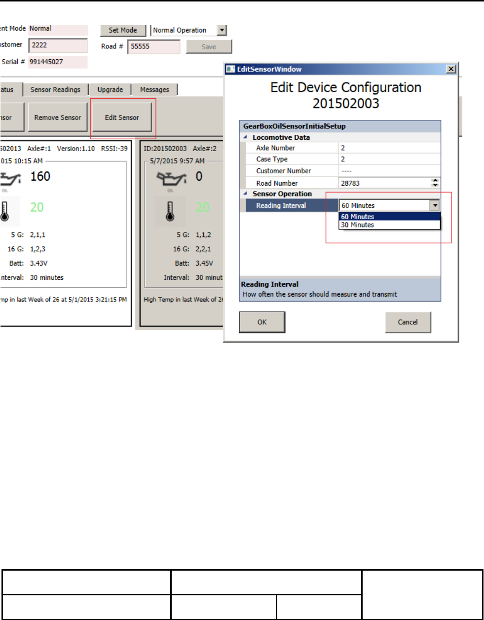
5.8` To modify an existing sensor’s settings, highlight a sensor tile that needs to be updated. Select the
EDIT SENSOR button.
5.9 In the new window, update the axle position and road number as required. Verify the reading interval is
set for one (1) hour. Select the OK button at the bottom of the window.
5.10 Set the customer name, road number, and axle position for each sensor.
5.11 Allow the sensor to pair such the tiles update with the new information. This may take up to one hour.
5.12 Once all sensors are programmed, remove the CMU download cable and re-connect the Ethernet cable
to port E-NET 03.
6.0 READING OIL LEVELS DURING LOCOMOTIVE MAINTENANCE CYCLES
This section outlines the steps required to record the oil levels during routine locomotive maintenance or combo
servicing. The USB port on the gateway can be used to quickly read the gear case oil levels, update sensor information,
and/or update hardware firmware as needed.
This method will not validate communications to the CMU.
6.1 Locate the following required equipment:
a) Laptop or Toughbook
b) USB Cable (Type A USB to Type B USB)
6.2 Connect the USB cable to the Gateway’s USB port and the PC’s USB port. Wait about 15 seconds for
the PC to acknowledge the connection.
6.3 Open the “DHMS Gateway Configuration Manager” and verify the software version is 1.0.8.0 or newer.
The version number is shown in the upper left corner of the application window.
6.4 Select the “Serial/USB” radio button in the upper right corner. The serial port number will automatically
be displayed in the window.
6.5 Select the OPEN CONNECTION button to begin communications with the Gateway.
6.6 The window for the application should look similar to Figure 6.1.
6.7 Enter the gear case oil level percentages (shown next to the “oil can” icon) into the appropriate e-services
tasks for each axle position equipped with DHMS sensors. Defects will be created for any positions
requiring servicing with oil.

GE Transportation Systems
RF Gear Case Sensor
6/3/15
Installation Instructions
Rev. A1
Author: David Petersen
Approval: Sethu Madhavan
84A234272AB
Issued: GET Engineering, 6/21/13
BUS. AREA: Loco
Sheet 17 of 31
This Drawing is the Property of GENERAL ELECTRIC COMPANY, TRANSPORTATION SYSTEMS DIVISION. This drawing is loaned upon the express
condition that it shall not be reproduced in any manner, and shall be returned upon demand. It is submitted for evaluation purposes and it, and the information
contained therein, shall not be otherwise used nor disclosed to third parties without written permission of General Electric Co.
PLEASE NOTE THAT AXLES MAY NOT BE SEQUENTIAL IN THE GATEWAY CONFIGURATION
MANAGER (AS SHOWN BELOW)
Figure 6.1: Sensor Oil Level Readings
7.0 UPDATING SENSOR & GATEWAY FIRMWARE
Both the sensor and gateway contain embedded firmware. Each gear case sensor should have the same
firmware version number and match the version shown in Table B1 of Appendix B. The gateway’s
firmware should also match Table B1. The instructions to update the firmware are given below.
The firmware for both the sensor and gateway are contained within the DHMS Gateway Configuration
Manager application.
100
100
82
91
77
100
GE Transportation Systems
RF Gear Case Sensor
6/3/15
Installation Instructions
Rev. A1
Author: David Petersen
Approval: Sethu Madhavan
84A234272AB
Issued: GET Engineering, 6/21/13
BUS. AREA: Loco
Sheet 18 of 31
This Drawing is the Property of GENERAL ELECTRIC COMPANY, TRANSPORTATION SYSTEMS DIVISION. This drawing is loaned upon the express
condition that it shall not be reproduced in any manner, and shall be returned upon demand. It is submitted for evaluation purposes and it, and the information
contained therein, shall not be otherwise used nor disclosed to third parties without written permission of General Electric Co.
GATEWAY FIRMWARE UPDATE
7.1 Connect the PC to the CMU at E-NET 03 or the gateway’s USB port.
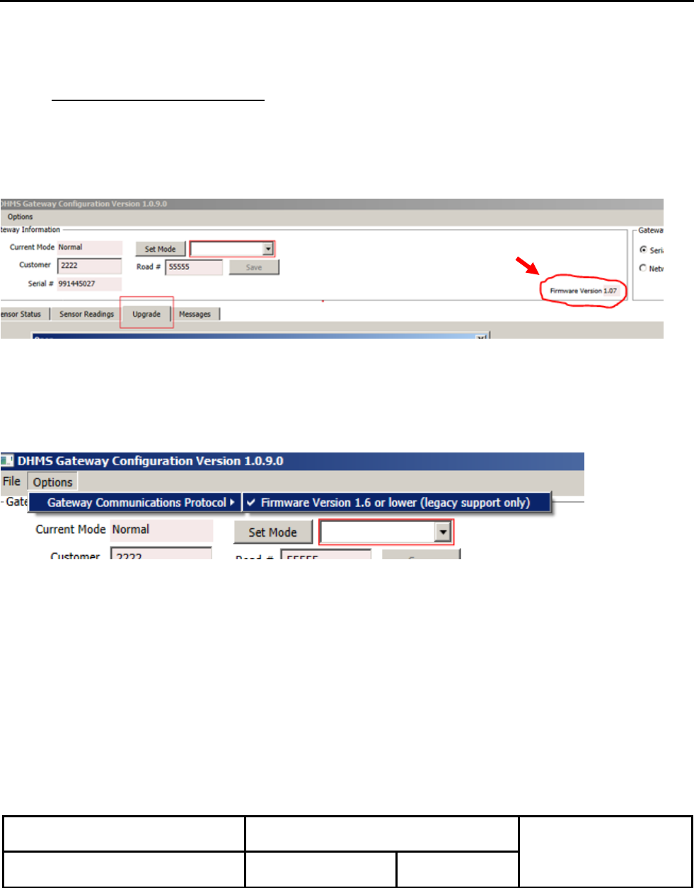
7.2 Open Gateway Configuration Manager. Look at the Gateway’s current software version.
7.3 If this version is 1.06, enable the "Legacy Communications" options via the "Options->Gateway
Communications Protocol->Firmware Version 1.6 or lower (legacy support only)" option as shown
below. See the check there. Click so it can be checked.
If the version is 1.07 or higher, make sure the box is NOT checked.
This is only necessary in order to use an older communications protocol, but in order to communicate;
it must initially use the old version. All gateways should be updated to the new firmware during their
next maintenance cycle.

GE Transportation Systems
RF Gear Case Sensor
6/3/15
Installation Instructions
Rev. A1
Author: David Petersen
Approval: Sethu Madhavan
84A234272AB
Issued: GET Engineering, 6/21/13
BUS. AREA: Loco
Sheet 19 of 31
This Drawing is the Property of GENERAL ELECTRIC COMPANY, TRANSPORTATION SYSTEMS DIVISION. This drawing is loaned upon the express
condition that it shall not be reproduced in any manner, and shall be returned upon demand. It is submitted for evaluation purposes and it, and the information
contained therein, shall not be otherwise used nor disclosed to third parties without written permission of General Electric Co.
7.4 For Ethernet connection, select the NETWORK HOST radio button for Ethernet in the upper right corner.
And Select the OPEN CONNECTION button to begin communications with the Gateway. Verify the
Network address is10.10.9.252. Verify the PORT ID to 10001
For USB connection, select the SERIAL/USB radio button and the highlighted COMM port.
7.5 Click the "Upgrade" tab and then in the "Gateway Firmware Upgrade" area use the "Select File" button to
browse to the "DHMS Gateway Firmware Version 1.7 Upgrade .bin" file. (firmware .bin file is under DHMS
installation folder. C:\Program Files (x86)\Phase IV Engineering\GE DHMS\)
7.6 Click the "Commit" button in the "Gateway Firmware Upgrade" area. You will get a message confirming
the upgrade:
GE Transportation Systems
RF Gear Case Sensor
6/3/15
Installation Instructions
Rev. A1
Author: David Petersen
Approval: Sethu Madhavan
84A234272AB
Issued: GET Engineering, 6/21/13
BUS. AREA: Loco
Sheet 20 of 31
This Drawing is the Property of GENERAL ELECTRIC COMPANY, TRANSPORTATION SYSTEMS DIVISION. This drawing is loaned upon the express
condition that it shall not be reproduced in any manner, and shall be returned upon demand. It is submitted for evaluation purposes and it, and the information
contained therein, shall not be otherwise used nor disclosed to third parties without written permission of General Electric Co.
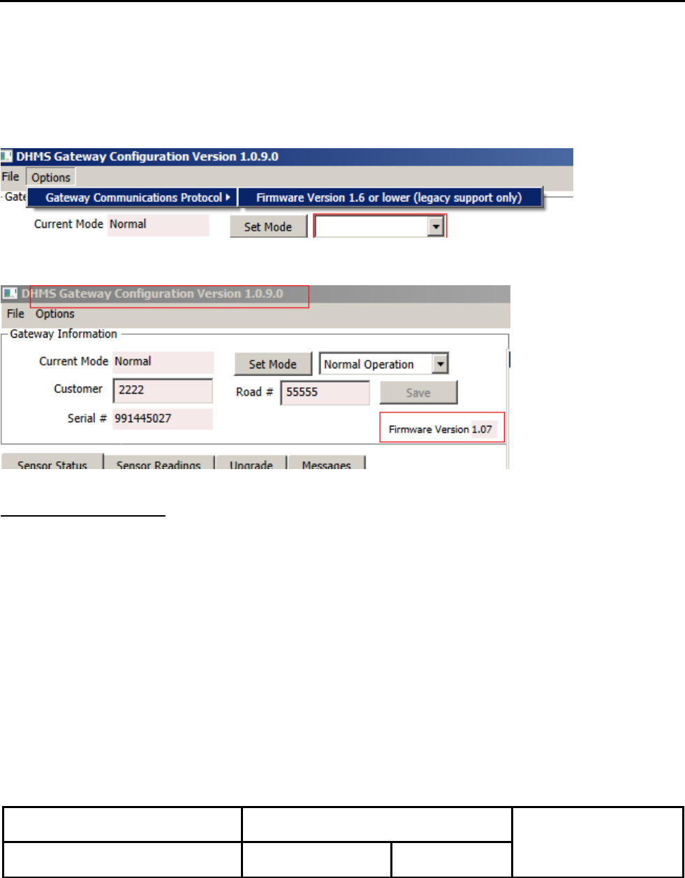
7.7 Click OK and close the Gateway Configuration Manager software.
7.8 Wait about 15 seconds, then open the Gateway Configuration Manager.
7.9. Now de-select the legacy communications protocol by deselecting the "Options->Gateway
Communications Protocol->Firmware Version 1.6 or lower (legacy support only)".
7.10 Now the Gateway Firmware Version shows as 1.07.
Sensor Firmware Update
7.11 Add sensors to the configuration by using the "Add Sensor" button. In the "DeviceType" section of the
Add Device form, select "GearBoxOilSensor". Select the reading interval as 30min. Note that this interval

GE Transportation Systems
RF Gear Case Sensor
6/3/15
Installation Instructions
Rev. A1
Author: David Petersen
Approval: Sethu Madhavan
84A234272AB
Issued: GET Engineering, 6/21/13
BUS. AREA: Loco
Sheet 21 of 31
This Drawing is the Property of GENERAL ELECTRIC COMPANY, TRANSPORTATION SYSTEMS DIVISION. This drawing is loaned upon the express
condition that it shall not be reproduced in any manner, and shall be returned upon demand. It is submitted for evaluation purposes and it, and the information
contained therein, shall not be otherwise used nor disclosed to third parties without written permission of General Electric Co.
will not go into effect until after the firmware upgrade has completed, as this is a new message in the
firmware. Click OK to add the sensor.
Now a new sensor has been added.

GE Transportation Systems
RF Gear Case Sensor
6/3/15
Installation Instructions
Rev. A1
Author: David Petersen
Approval: Sethu Madhavan
84A234272AB
Issued: GET Engineering, 6/21/13
BUS. AREA: Loco
Sheet 22 of 31
This Drawing is the Property of GENERAL ELECTRIC COMPANY, TRANSPORTATION SYSTEMS DIVISION. This drawing is loaned upon the express
condition that it shall not be reproduced in any manner, and shall be returned upon demand. It is submitted for evaluation purposes and it, and the information
contained therein, shall not be otherwise used nor disclosed to third parties without written permission of General Electric Co.
7.12 Once all sensors have been added to the configuration, click the "Upgrade" tab. Then select the "Sensor
Firmware Upgrade" file. Highlight the ID's of the sensors you wish to upgrade, then click "Commit". Note
that you may have to wait one or more communication cycles (this means 60min maximum) for the
sensors to download and upgrade themselves.
GE Transportation Systems
RF Gear Case Sensor
6/3/15
Installation Instructions
Rev. A1
Author: David Petersen
Approval: Sethu Madhavan
84A234272AB
Issued: GET Engineering, 6/21/13
BUS. AREA: Loco
Sheet 23 of 31
This Drawing is the Property of GENERAL ELECTRIC COMPANY, TRANSPORTATION SYSTEMS DIVISION. This drawing is loaned upon the express
condition that it shall not be reproduced in any manner, and shall be returned upon demand. It is submitted for evaluation purposes and it, and the information
contained therein, shall not be otherwise used nor disclosed to third parties without written permission of General Electric Co.
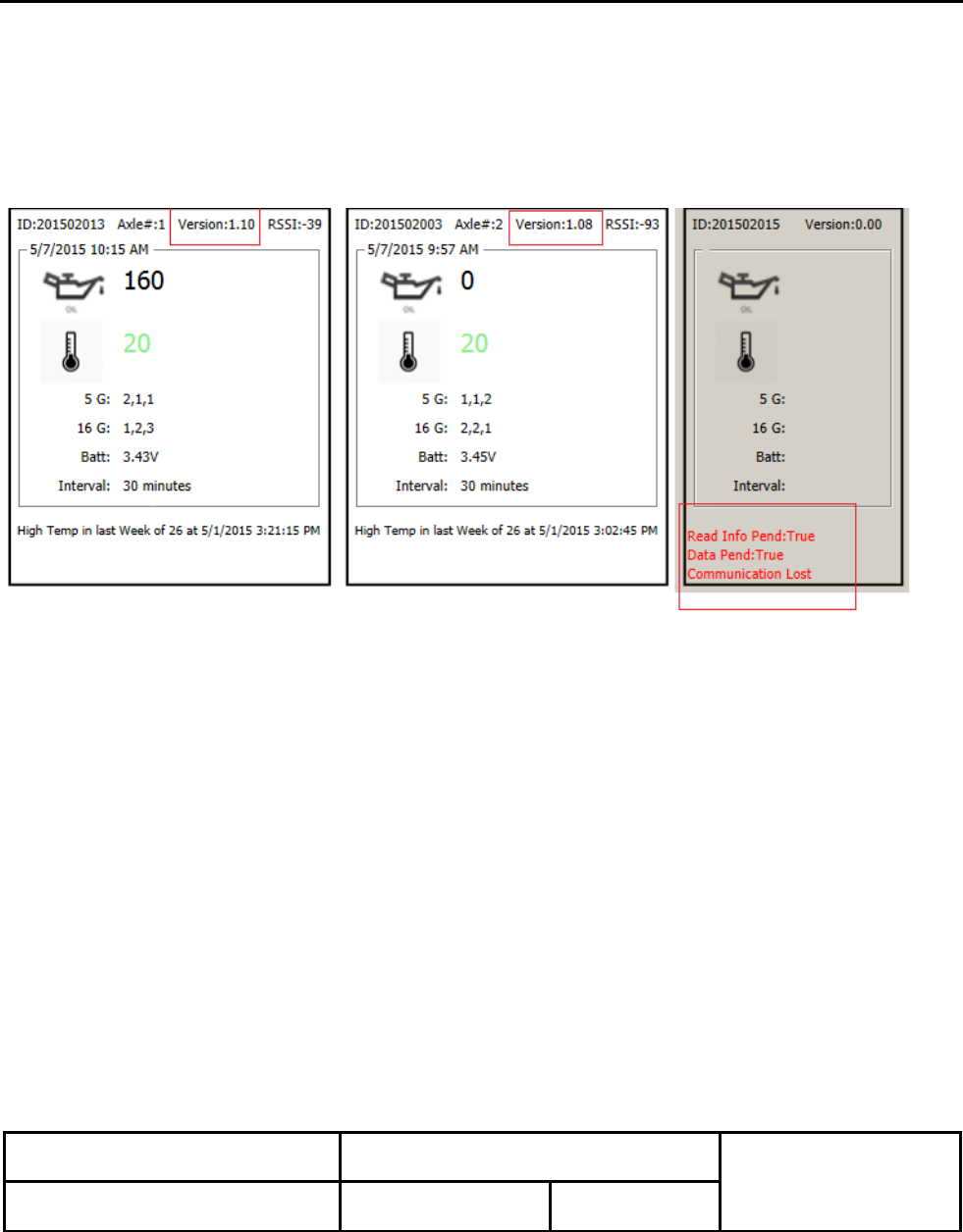
The system should remain on until all sensors shown a "Version 1.10" in their version windows.
Below left to right:
Left: v1.10 successfully upgraded and got reading from sensor.
Middle: sensor firmware not upgraded, but got the reading from sensor.
Right: still waiting the 1st cycle to happen, no sensor data yet.
7.13 Finally, once all sensors have been configured correctly, change the reading interval back to 60 minutes.
GE Transportation Systems
RF Gear Case Sensor
6/3/15
Installation Instructions
Rev. A1
Author: David Petersen
Approval: Sethu Madhavan
84A234272AB
Issued: GET Engineering, 6/21/13
BUS. AREA: Loco
Sheet 24 of 31
This Drawing is the Property of GENERAL ELECTRIC COMPANY, TRANSPORTATION SYSTEMS DIVISION. This drawing is loaned upon the express
condition that it shall not be reproduced in any manner, and shall be returned upon demand. It is submitted for evaluation purposes and it, and the information
contained therein, shall not be otherwise used nor disclosed to third parties without written permission of General Electric Co.
8.0 TROUBLESHOOTING
This document outlines the steps required to troubleshoot and re-program the RF Gear Case Sensor (RGS)
on the locomotive.
Use this section when troubleshooting the Gateway’s communication to the CMU and gear case sensors.
Once the communications is established within the system, the RGS sensors ID’s, road number, or axle
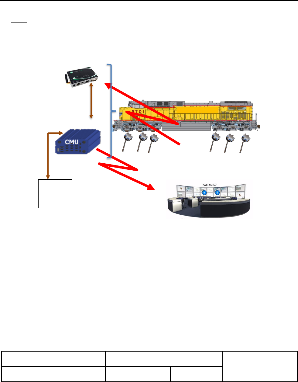
position can be programmed. An overview of the communication paths are shown in Figure 8.1.
Communications from the sensor to the gateway is through a RF 2.4 GHz link. Communications from the
gateway to the CMU is through a wired Ethernet link.
GE Transportation Systems
RF Gear Case Sensor
6/3/15
Installation Instructions
Rev. A1
Author: David Petersen
Approval: Sethu Madhavan
84A234272AB
Issued: GET Engineering, 6/21/13
BUS. AREA: Loco
Sheet 25 of 31
This Drawing is the Property of GENERAL ELECTRIC COMPANY, TRANSPORTATION SYSTEMS DIVISION. This drawing is loaned upon the express
condition that it shall not be reproduced in any manner, and shall be returned upon demand. It is submitted for evaluation purposes and it, and the information
contained therein, shall not be otherwise used nor disclosed to third parties without written permission of General Electric Co.
Note: After testing is complete, remember remove the CMU test cable and re-install the original cable
to CMU port E-NET 03.
Figure 8.1: DHMS Communication.
8.1 Equipment Required
a. Laptop or Toughbook
b. Ethernet cable for CMU Download
RF (2.4GHz) Communications
Sensor to Gateway
RF to RM&D Center
Ethernet
Comm.
.
E- NET 03 E-NET 02
PC or
Tough
Book
Gateway

GE Transportation Systems
RF Gear Case Sensor
6/3/15
Installation Instructions
Rev. A1
Author: David Petersen
Approval: Sethu Madhavan
84A234272AB
Issued: GET Engineering, 6/21/13
BUS. AREA: Loco
Sheet 26 of 31
This Drawing is the Property of GENERAL ELECTRIC COMPANY, TRANSPORTATION SYSTEMS DIVISION. This drawing is loaned upon the express
condition that it shall not be reproduced in any manner, and shall be returned upon demand. It is submitted for evaluation purposes and it, and the information
contained therein, shall not be otherwise used nor disclosed to third parties without written permission of General Electric Co.
8.2 PC Communications to the Gateway
8.2.1 Remove the Ethernet Cable from port E-NET 03 on the CMU.
8.2.2 Connect the yellow CMU download cable to port E-NET 03 and to the PC.
8.2.3 Verify the DHMS Gateway’s Ethernet cable is connected to CMU port E-NET 02 and to the DHMS
Gateway’s Ethernet port.
8.2.4 Open the “DHMS Gateway Configuration Manager” and verify the software version is 1.0.8.0 or newer.
8.2.5 The version number is shown in the upper left corner of the application window.
8.2.6 Select the NETWORK HOST radio button for Ethernet in the upper right corner.
8.2.7 Verify the Network address to 10.10.9.252, change if required
8.2.8 Verify the PORT ID is 10001, change if required
8.2.9 Select the OPEN CONNECTION button to begin communications with the Gateway.
8.2.10 The DHMS window for the application should look similar to Figure 8.2.
Note: If using a PC, see Appendix A for help in setting the PC’s IP address if you cannot
establish an Ethernet communication link with the Gateway.
8.3 Ethernet Communications to the Gateway
8.3.1 Verify the Gateway’s is communicating to the PC. The window should look like Figure 8.2.
8.3.2 The message in the bottom left corner of the display should say that communication is established.
8.3.3 If there is no communications to the Gateway, verify the Ethernet cables are connected correctly.
8.3.4 If there is still no response, pin-out the DHMS Gateway Ethernet cable and replace if needed.

GE Transportation Systems
RF Gear Case Sensor
6/3/15
Installation Instructions
Rev. A1
Author: David Petersen
Approval: Sethu Madhavan
84A234272AB
Issued: GET Engineering, 6/21/13
BUS. AREA: Loco
Sheet 27 of 31
This Drawing is the Property of GENERAL ELECTRIC COMPANY, TRANSPORTATION SYSTEMS DIVISION. This drawing is loaned upon the express
condition that it shall not be reproduced in any manner, and shall be returned upon demand. It is submitted for evaluation purposes and it, and the information
contained therein, shall not be otherwise used nor disclosed to third parties without written permission of General Electric Co.
8.4 Sensor Communications to the Gateway
8.4.1 Once the Gateway is talking to the PC, select the “Sensor Status” tab on the screen.
8.4.2 Each of the sensors currently programmed into the sensor will be displayed in the window.
8.4.3 Each panel within this tab is an individual sensor. Normally, there should be six sensors installed and
six panels displayed.
8.4.4 If the sensor ID is “paired” and communicating correctly with the Gateway, the oil level and temperature
will be displayed. In addition, panel will display the locomotives axle position, sensor software version,
and RF signal strength at the top of each panel.
8.4.5 Verify the time and date is current. The time stamps shown should be within a 2 hour window of each
other, and 4 hours from local time (time offset may vary by time zone). See Figure 8.2.
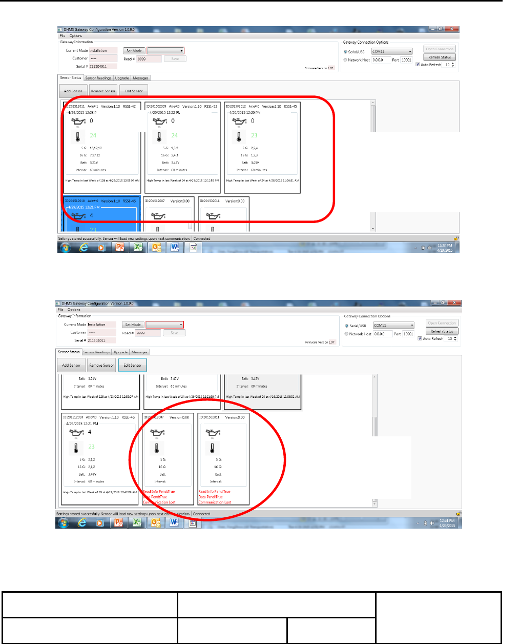
8.4.6 Individual sensors that are not paired correctly will either show dates that are grossly off from the
current date or not paired at all as shown in Figure 8.3.
8.5 Correcting Sensor that are not Communicating.
8.5.1 On a piece of paper, note the ID numbers of each sensor and it’s programed positions from each of the
senor panels displayed. There should be six sensors in total, one per axle. Note which sensors were
not communicating to the gateway.
8.5.2 Set the Gateway in Installation Mode. From the drop down menu in upper left of the window, select
INSTALLATION MODE and then select SET. The current mode will change to INSTALLATION. This
will temporarily speed up the communication times and make troubleshooter quicker. Installation mode
will take effect at the next communication cycle (within 1 hour) and last for 2 hours.
8.5.3 From under the locomotive, verify there is one sensor on each traction motor gear case, six in total.
Compare the ID numbers installed to the list of each sensor and its axle position, axle 1 through axle 6.
Note, there may be less than six sensors installed due to a combo change-out. Contact the shop TA if
a replacement sensor is required.
8.5.4 Verify the Serial Number on the sensors match the ID numbers from the Gateway. Pay special
attention to those sensors not communicating. The Gateway will need to be updated to reflect the
actual sensors ID numbers installed.
8.5.5 Inspect each sensor for damage (or significant oil leakage). Pay particular attention to sensors that are
not communicating. Replace any missing hardware and replace any sensor missing its black protective
cover.
8.5.6 From inside the cab, verify the sensor ID numbers match the programed values in the sensor panels.
To remove an incorrect sensor, highlight the senor panel for that sensor and select the REMOVE
button. This will remove the senor from the display window.
8.5.7 To add a new sensor, select the ADD tab. Enter the sensor’s Serial Number as listed on the sensor. In
addition, add in the customer name, road number, and axle position. Then select the SAVE button.
This will add the sensor to the display window. Note, it may take up to1 hour for the new sensor to
“pair” to the Gateway and establish communication.
8.5.8 For sensors that are not communicating, try to REMOVE the sensor and ADD the same sensor back
into the Gateway. Again, this may take up to one hour to pair and begin to communicate.
8.5.9 Any sensor that is still is not communicating after this step, should be replaced with a new sensor.
GE Transportation Systems
RF Gear Case Sensor
6/3/15
Installation Instructions
Rev. A1
Author: David Petersen
Approval: Sethu Madhavan
84A234272AB
Issued: GET Engineering, 6/21/13
BUS. AREA: Loco
Sheet 28 of 31
This Drawing is the Property of GENERAL ELECTRIC COMPANY, TRANSPORTATION SYSTEMS DIVISION. This drawing is loaned upon the express
condition that it shall not be reproduced in any manner, and shall be returned upon demand. It is submitted for evaluation purposes and it, and the information
contained therein, shall not be otherwise used nor disclosed to third parties without written permission of General Electric Co.
Figure 8.2: Normal Communications for Gateway and Sensor Operation.
Figure 8.3: Disrupted Communications for Gateway and Sensor Operation.
Sensors not paired
correctly to Gateway.
No communications.
Four of six sensors paired
correctly;
- Times current and with limits
- RSSI values OK.
100
100
100

GE Transportation Systems
RF Gear Case Sensor
6/3/15
Installation Instructions
Rev. A1
Author: David Petersen
Approval: Sethu Madhavan
84A234272AB
Issued: GET Engineering, 6/21/13
BUS. AREA: Loco
Sheet 29 of 31
This Drawing is the Property of GENERAL ELECTRIC COMPANY, TRANSPORTATION SYSTEMS DIVISION. This drawing is loaned upon the express
condition that it shall not be reproduced in any manner, and shall be returned upon demand. It is submitted for evaluation purposes and it, and the information
contained therein, shall not be otherwise used nor disclosed to third parties without written permission of General Electric Co.
9.0 DATA LOG DOWNLOAD
9.1 Connect a PC to the gateway (USB) or CMU (Ethernet) and open the DHMS Gateway Configuration software.
9.2 Verify the sensors are communicating from the “Sensor Status” tab. The oil level, temperature, time, and date
should be displayed.
9.3 In the main window, select the “DataBuffer” tab. The buffer should contain data for each sensor, up to 300 lines in
total.
9.4 Then select “Export” button at the right hand side of the window. Save the data file to your desktop.
9.5 Remove the test cable and restore the locomotive.

GE Transportation Systems
RF Gear Case Sensor
6/3/15
Installation Instructions
Rev. A1
Author: David Petersen
Approval: Sethu Madhavan
84A234272AB
Issued: GET Engineering, 6/21/13
BUS. AREA: Loco
Sheet 30 of 31
This Drawing is the Property of GENERAL ELECTRIC COMPANY, TRANSPORTATION SYSTEMS DIVISION. This drawing is loaned upon the express
condition that it shall not be reproduced in any manner, and shall be returned upon demand. It is submitted for evaluation purposes and it, and the information
contained therein, shall not be otherwise used nor disclosed to third parties without written permission of General Electric Co.
APPENDIX A: LOADING DHMS SOFTWARE ON A PC
This section is the installation of the Gateway Configuration Manager Software on to a PC. This is a onetime
setup for installation and configuration of the DHMS reader software. Once configured, the software will save
the settings for future use.
A1 Check the PC for the version of DHMS software currently installed on the laptop, if any. Open the
“Gateway Configuration Manager” and verify the software version shown in the header is version
1.0.10.0.
A2. If not current, remove the installed Phase IV DHMS software using the Add/Remove application in the
PC’s Control Panel.
A3 Copy the latest version of DHMS software to the PC desktop using the link below.
http://www.phaseivengr.com/wp-content/uploads/2015/05/GE-DHMS-Version-1.12.zip
Note: This link is for reference only. Verify with Engineering that this link contains the latest READER
and SENSOR application software.
A4 Run the application file with the .msi extension to load the software on the PC. The file will extract the
two programs and place two shortcuts on the desktop,
A5 Open the DHMS_Gateway_Configuration_Manager.
A6 Select the Network Host radio button at the top right corner of the application.
A7 Set the IP address (Network Host ID) to 10.10.9.252 and the port to 10001.
A8 Select the Open Connection button.
A.9 If no response, you will need to reconfigure you laptop’s IP address per the steps below. To configure
your PC’s Ethernet port to talk to the gateway (shown for Windows 7):
a. Open the PC’s control panel from the Window’s START icon.
b. Double click on the “Network and Internet” heading on the left side of the window.
c. Double click on the “Network and Sharing Center” heading on the top left side of the window.
d. Double click on the “Change adapter settings” on the left side menu of the window.
e. Double click on the “Local Area Connection” icon in the window.
f. Select the “Properties” button at the bottom of the window. Select the “YES” button to allow
the change.
g. Highlight the “InternetProtocolVersionTCP/IPv4” connection from the middle on the
window. Do not uncheck any box.
h. When highlighted, select “Properties” button at the bottom of the window.
i. In the “Properties” window, select the “Use the following IP address” radio button.
j. Set the IP address for the laptop’s port to 10.10.9.1 (old IP was 128.0.0.32)
k. Set the Subnet mask to 255.255.255.0
l. Select to OK button to close the window.
m. Select the CLOSE button the close the next window.
n. Close out the remaining control panel windows.
A.10 Re-open the DMHS application with the corrected IP address.
A.11 Select the Open Connection button.
A.12 Proceed to read or program the sensors as described within the body of this document.

GE Transportation Systems
RF Gear Case Sensor
6/3/15
Installation Instructions
Rev. A1
Author: David Petersen
Approval: Sethu Madhavan
84A234272AB
Issued: GET Engineering, 6/21/13
BUS. AREA: Loco
Sheet 31 of 31
This Drawing is the Property of GENERAL ELECTRIC COMPANY, TRANSPORTATION SYSTEMS DIVISION. This drawing is loaned upon the express
condition that it shall not be reproduced in any manner, and shall be returned upon demand. It is submitted for evaluation purposes and it, and the information
contained therein, shall not be otherwise used nor disclosed to third parties without written permission of General Electric Co.
APPENDIX B: SOFTWARE VERSION CONTROL AND MANAGEMENT
This Appendix defines the software version numbers that should loaded onto the DHMS hardware. The version numbers
may differ from customer to customer, and/or fleet to fleet. There are three different software/firmware modules
required for the DHMS system to operate properly. These are:
1) RGS sensor: Firmware loaded within the gear case sensor.
2) DHMS Gateway: Firmware loaded onto the Gateway
3) DHMS Gateway Configuration Manager: Reader software loaded onto a Tough Book or PC.
The firmware is available using the Gateway Configuration Manager under the UPGRADE tab. These modules are test
as a suite and should be loaded onto the DHMS hardware only in approved sets as listed in Table B1 below.
The firmware for the sensors and gateway should be checked periodically to make sure they comply with the table
below. Hardware (sensors or gateways) with older version numbers (lower numbers) should be updated to comply with
the Table B1.
Table B1 is intended to show approved software and firmware combinations. DHMS hardware should only be installed
on customer road numbers as indicated by approved e-Service programs. The e-Service program will also list the correct
CMU software version to off-board the DHMS data.
Table B1: Approved DHMS Software and Firmware
Customer
Road
Road
Number
Range
Gateway
Configuration
Manager
Gateway
Firmware
Sensor
Firmware
Comments
CP
All
1.0.10
1.08
1.11
Excludes special FTON units.