GE CDW9380N20SS User Manual DISHWASHER Manuals And Guides L0709194
GE Dishwasher Manual L0709194 GE Dishwasher Owner's Manual, GE Dishwasher installation guides
User Manual: GE CDW9380N20SS CDW9380N20SS GE DISHWASHER - Manuals and Guides View the owners manual for your GE DISHWASHER #CDW9380N20SS. Home:Kitchen Appliance Parts:GE Parts:GE DISHWASHER Manual
Open the PDF directly: View PDF ![]() .
.
Page Count: 13

Appliances
Installation Instructions
Built-In Dishwasher
If you have questions, call 800.GE.CARES{800.432.2737} or visit our website at: www.ge.com
In Canada call 1-800-561-3344 or www.geappliances.ca
BEFORE YOU BEGIN
Read these instructions completely and
carefully.
IM PO RTANT-The dishwasherMUST
beinstalledtoallowforfutureremovalfromtheenclosure
if service is required.
IM PORTANT-Observe allgoverningcodes and
ordinances.
• Note to Installer- Be sure to leavethese instructionsforthe
consumer's and localinspector'suse.
• Note to Consumer - Keep these instructionswith your
Owner's Manual for future reference.
• Skill Level - Installation of this dishwasher requires
basic mechanical, electrical and plumbing skills. Proper
installation is the responsibility of the installer. Product
failure due to improper installation is not covered under
the GE Appliance Warranty. See warranty information.
• Completion Time - 1 to 3 Hours. New installations require
more time than replacement installations.
If you received a damaged dishwasher, you should
immediately contact your dealer or builder.
Optional Accessories - See the Owner's Manual for available
custom panel kits.
FOR YOUR SAFETY
Read and observe all CAUTIONS and WARNINGS
shown throughout these instructions. While performing
installations described in this booklet, gloves and either
safety glasses or goggles should be worn.
Y
READ CAREFULLY.
KEEP THESE INSTRUCTIONS.
PDW8200 Series
PDW8400 Series
PDW8700 Series
PDW8800 Series
PDW8900 Series
PDW9200 Series
PDW9700 Series*
PDW9800 Series
PDW9900 Series
CDW9000 Series
*For PDW9700 Series also refer to the Instructions
provided on the template packed with that model.
(WD35XlOO5)
(__) imag ination at work
Installation Preparation
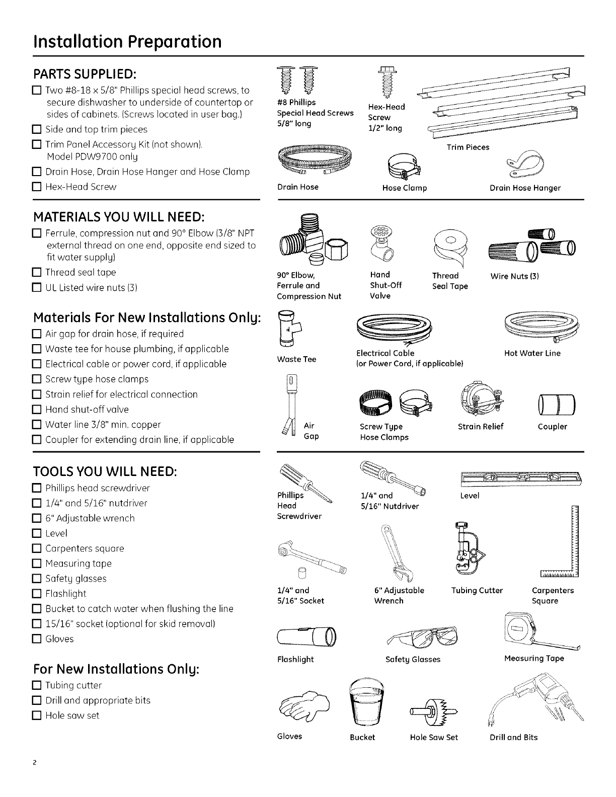
PARTS SUPPLIED:
[] Two #8-18 x 5/8" Phillips special head screws, to
secure dishwasher to underside of countertop or
sides of cabinets. (Screws located in user bag.)
[] Side and top trim pieces
[] Trim Panel Accessory Kit (not shown).
Model PDW9700 only
[] Drain Hose, Drain Hose Hanger and Hose Clamp
[] Hex-Head Screw
#8 Phillips Hex-Head
SpecialHeadScrews Screw
5/8" long 1/2" long
Trim Pieces
Drain Hose Hose Clamp Drain Hose Hanger
MATERIALS YOU WILL NEED:
[] Ferrule, compression nut and 90° Elbow (3/8" NPT
external thread on one end, opposite end sized to
fit water supply)
[] Thread seal tape
[] UL Listed wire nuts (3)
90° Elbow,
Ferrule and
Compression Nut
Materials For New Installations Onlg: _
[] Air gap for drain hose, if required
[] Waste tee for house plumbing, if applicable
[] Electrical cable or power cord, if applicable waste Tee
[] Screw type hose clamps J_
[] Strain relief for electrical connection
[] Hand shut-off valve
[] Water line 3/8" min. copper Air
[] Coupler for extending drain line, if applicable Gap
TOOLS YOU WILL NEED:
[] Phillips head screwdriver
[] 1/4" and 5/16" nutdriver
[] 6" Adjustable wrench
[] Level
[] Carpenters square
[] Measuring tape
[] Safety glasses
[] Flashlight
[] Bucket to catch water when flushing the line
[] 15/16" socket (optional for skid removal)
[] Gloves
For New Installations Only:
[] Tubing cutter
[] Drill and appropriate bits
[] Hole saw set
Hand Thread
Shut-Off Seal Tape
Valve
Electrical Cable
(or Power Cord, if applicable)
Screw Type
Hose Clamps
Wire Nuts (3)
Hot Water Line
O
Strain Relief Coupler
Phillips
Head
Screwdriver
114" and
5116" Socket
5/16" Nutdriver
6" Adjustable
Wrench
Level
Tubing Cutter
J
Carpenters
Square
Flashlight SafetyGlasses Measuring Tape
Gloves Bucket Hole Saw Set Drill and Bits
Installation Preparation
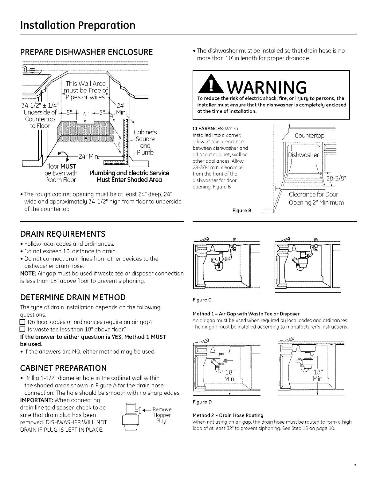
PREPARE DISHWASHER ENCLOSURE
]4-i/2" _+1/4"
Underside of
Countertop
to Floor
)es or wires
Square
and
Plumb
Floor MUST
be Evenwith
Room Floor Plumbing and Electric Service
Must Enter Shaded Area
• The rough cabinet opening must be at least 24" deep, 24"
wide and approximatelg 34-1/2" high from floor to underside
of the countertop,
• The dishwasher must be installed so that drain hose is no
more than 10' in length for proper drainage.
WARNING
To reduce the risk of electric shock, fire, or injurg to persons, the
installer must ensure that the dishwasher is completely enclosed
at the time of installation.
CLEARANCES: When
installed into a corner,
allow 2" min. clearance
between dishwasher and
adjacent cabinet, wall or
other appliances. Allow
28-3/8" min. clearance
from the front of the
dishwasher for door
opening. Figure B
Figure B
Countertop
28-]/8"
Clearance for Door
Opening 2" Minimum
DRAIN REQUIREMENTS
•Followlocolcodesond ordinonces.
• Do not exceed 10' distonce to droin,
• Do not connect droin linesfrom other devices to the
dishwosher droin hose.
NOTE: Air gop must be used ifwoste tee or disposer connection
isless thon 18" obove floor to prevent siphoning.
DETERMINE DRAIN METHOD
The tgpe of drain installation depends on the following
questions,
[] Do local codes or ordinances require on air gap?
[] Is woste tee less than 18" obove floor?
If the answer to either question is YES, Method i MUST
be used.
• If the answers ore NO, either method mog be used.
CABINET PREPARATION
• Drill o i-1/2" diameter hole in the cabinet wall within
the shaded areas shown in Figure Afor the drGin hose
connection. The hole should be smooth with no sharp edges.
IMPORTANT:When connecting
drain line to disposer, check to be _ 41--Remove
sure thGt drGin plug has been [_= Hopper
removed. DISHWASHERWILL NOT Plug
DRAINIF PLUGISLEFTIN PLACE.
Figure C
Method 1 - Air Gap with Waste Tee or Disposer
An air gap must be used when required bg local codes and ordinances.
The air gap must be installed according to manufacturer's instructions.
Figure D
18"
Method 2 - Drain Hose Routing
When not using an air gap, the drain hose must be routed to form a high
loop of at least 32" to prevent siphoning. See Step 15 on page 10.
Installation Preparation
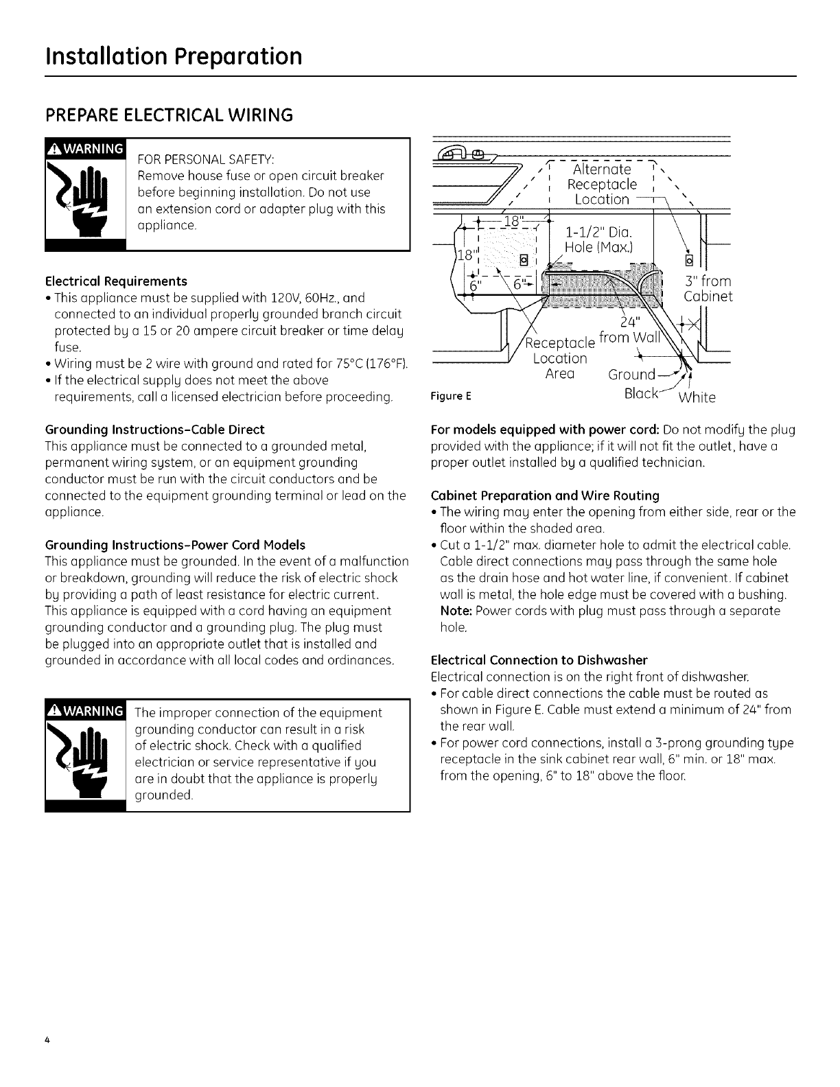
PREPARE ELECTRICAL WIRING
FORPERSONALSAFETY:
Remove house fuse or open circuit breaker
before beginning installation. Do not use
an extension cord or adapter plug with this
appliance.
Electrical Requirements
• This appliance must be supplied with 120V, 60Hz.,and
connected to an individual properl9 grounded branch circuit
protected by a 15 or 20 ampere circuit breaker or time delag
fuse.
• Wiring must be 2 wire with ground and rated for 75°C(176°F).
• If the electrical supply does not meet the above
requirements, call a licensed electrician before proceeding.
Grounding Instructions-Cable Direct
This appliance must be connected to a grounded metal,
permanent wiring system, or an equipment grounding
conductor must be run with the circuit conductors and be
connected to the equipment grounding terminal or lead on the
appliance.
Grounding Instructions-Power Cord Models
This appliance must be grounded. In the event of a malfunction
or breakdown, grounding will reduce the risk of electric shock
by providing a path of least resistance for electric current.
This appliance is equipped with a cord having an equipment
grounding conductor and a grounding plug. The plug must
be plugged into an appropriate outlet that is installed and
grounded in accordance with all local codes and ordinances.
The improper connection of the equipment
grounding conductor can result in a risk
of electric shock. Check with a qualified
electrician or service representative if you
are in doubt that the appliance is properly
grounded.
_ ,f Alternate -_,
I
,, Receptacle _ ",
,Location
1-1/2" Dia.
Hole (Hax.)
Location
Area
3" from
Cabinet
Figure E White
For models equipped with power cord: Do not modify the plug
provided with the appliance; if it will not fit the outlet, have a
proper outlet installed bg a qualified technician.
Cabinet Preparation and Wire Routing
• The wiring mag enter the opening from either side, rear or the
floor within the shaded area.
• Cut a 1-1/2" max. diameter hole to admit the electrical cable.
Cable direct connections mag pass through the same hole
as the drain hose and hot water line, if convenient. If cabinet
wall is metal, the hole edge must be covered with a bushing.
Note: Power cords with plug must pass through a separate
hole.
Electrical Connection to Dishwasher
Electrical connection is on the right front of dishwasher.
• For cable direct connections the cable must be routed as
shown in Figure E.Cable must extend a minimum of 24" from
the rear wall.
• For power cord connections, install a B-prong grounding type
receptacle in the sink cabinet rear wall, 6" min. or 18" max.
from the opening, 6" to 18" above the flooE
Installation Instructions
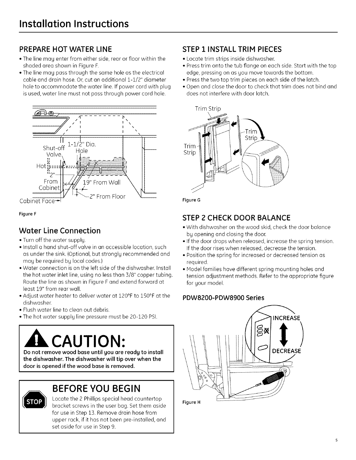
PREPARE HOT WATER LINE
• The line may enter from either side, rear or floor within the
shaded area shown in Figure F.
• The line may pass through the same hole as the electrical
cable and drain hose. Or, cut an additional 1-1/2" diameter
hole to accommodate the water line. If power cord with plug
is used, water line must not pass through power cord hole.
/I
/I
I
(I 1-1/_" Dia.
Shut-off Hole
Valve
Ii
14
Hot ...... _
U .... "
\
I\
I\
I\
From
Cabinet
Cabinet Face
Figure F
2" From Floor
Water Line Connection
• Turn off the water supply.
• Install a hand shut-off valve in an accessible location, such
as under the sink. (Optional, but strongly recommended and
may be required by local codes.)
• Water connection is on the left side of the dishwasher. Install
the hot water inlet line, using no less than 3/8" copper tubing.
Route the line as shown in Figure F and extend forward at
least 19" from rear wall.
• Adjust water heater to deliver water at 120°F to 150°F at the
dishwasher.
• Flush water line to clean out debris.
• The hot water supply line pressure must be 20-120 PSI.
CAUTION:
Do not remove wood base until you are ready to install
the dishwasher. The dishwasher will tip over when the
door is opened if the wood base is removed.
STEP i INSTALL TRIM PIECES
• Locate trim strips inside dishwasher.
• Presstrim onto the tub flange on each side. Start with the top
edge, pressing on as you move towards the bottom.
• Pressthe two top trim pieces on each side of the latch.
• Open and close the door to check that trim does not bind and
does not interfere with door latch.
Trim Strip
Trim -
Strip
Figure G
STEP 2 CHECK DOOR BALANCE
• With dishwasher on the wood skid, check the door balance
by opening and closing the door.
• If the door drops when released, increase the spring tension.
If the door rises when released, decrease the tension.
• Position the spring for increased or decreased tension as
required.
• Model families have different spring mounting holes and
tension adjustment methods. Refer to the appropriate figure
for your model.
PDW8200-PDW8900 Series
INCREASE
I)
DECREASE
BEFORE YOU BEGIN
Locate the 2 Phillips special head countertop
bracket screws in the user bag. Set them aside
for use in Step 13. Remove drain hose from
upper rack, if it has not been pre-installed, and
set aside for use in Step 9.
Figure H
Installation Instructions
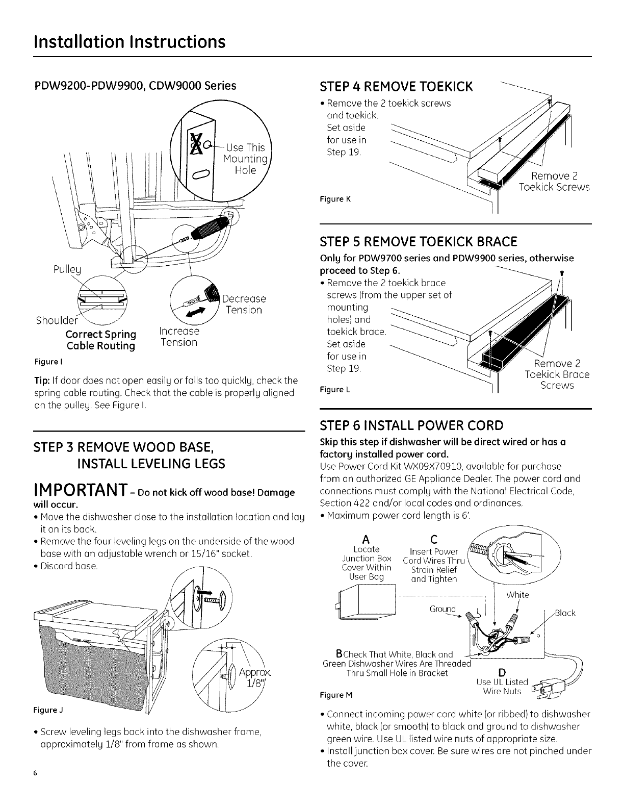
PDW9200-PDW9900, CDW9000 Series STEP 4 REMOVE TOEKICK
• Remove the 2 toekick screws
and toekick.
Set aside
for use in
Step 19.
Figure K
Remove 2
Toekick Screws
PulleL
Decrease
Tension
Shouldel
Correct Spring Increase
Cable Routing Tension
Figure I
Tip: If door does not open easily or falls too quickly, check the
spring cable routing. Check that the cable is properly aligned
on the pulley. SeeFigure I,
STEP 3 REMOVE WOOD BASE,
INSTALL LEVELING LEGS
IMPORTANT- Do not kick off wood base! Damage
will occur.
• Move the dishwasher close to the installation location and lay
it on its back.
• Remove the four leveling legs on the underside of the wood
base with an adjustable wrench or 15/16" socket.
• Discard base.
Figure J
• Screw leveling legs back into the dishwasher frame,
approximately 1/8" from frame as shown.
STEP 5 REMOVE TOEKICK BRACE
Only for PDW9700 series and PDW9900 series, otherwise
proceed to Step 6. t
• Remove the 2 toekick brace
screws (from the upper set of
mounting
holes) and
toekick brace.
Set aside
for use in
Step 19.
Figure L
Remove 2
Toekick Brace
Screws
STEP 6 INSTALL POWER CORD
Skip this step if dishwasher will be direct wired or has a
factory installed power cord.
Use Power Cord Kit WXO9X70910, available for purchase
from on authorized GEAppliance Dealer.The power cord and
connections must comply with the National Electrical Code,
Section 422 and/or local codes and ordinances.
• Maximum power cord length is 6'.
A
Locate Insert Power
Junct,onBox Cord WiresThru _ _.\\_-_--1- )
Cover Wlth,n Strain Relief _ _"_ J
User Bag and Tighten _- v_
BCheckThatWhite,Blackand _
GreenDishwasherWiresAreThreaded _
Thru SmallHolein Bracket D ///
UseULListed
Figure M Wire Nuts
• Connect incoming power cord white (or ribbed) to dishwasher
white, black (or smooth) to black and ground to dishwasher
green wire. Use UL listed wire nuts of appropriate size.
• Install junction box cover, Be sure wires are not pinched under
the cover,

Installation Instructions
STEP 7 INSTALL 90 ° ELBOW
• Wrap 90° elbow with thread seal tape.
• Install a 90° elbow onto the water valve.
Front of Dishwasher
• Push hose over the drain outlet on the back side of the
dishwasher. See Figure R Push the hose over the outlet and
against the shoulder stop.
• Tighten the hose clamp with a 1/4" nut driveE
Insulation
Blanket
900_
Elbow
Figure N
_ Water Valve
Bracket
e
Thread
SealTape
• Do not over tighten the 90° elbow, water valve bracket could
bend or water valve fitting could break.
• Position the end of the elbow to face the rear of the
dishwasher.
STEP 8 POSITION WATER LINE AND
HOUSE WIRING
• Position water supplg
line and house wiring
on the floor of the
opening to avoid
interference with
base of dishwasher
and components
under dishwasher.
Figure O
HOUSE
Water Wiring
Line
STEP 9 INSTALL DRAIN HOSE, GUIDE
THROUGH CABINET
• Stand the dishwasher upright.
• Get the drain hose set aside earlier and remove hose clamp
attached to hose.
Becareful not to damage Drain
the drain hose.
• Slipthe hose clamp
over the pump end
of the hose.
Drain
Outlet
Figure Q
House
Wiring
Power Cord
(If Used)
• Position the dishwasher in front of the opening. Insert drain
hose into the cabinet side. If power cord is used, guide the
end through a separate hole.
STEP 10 SLIDE DISHWASHER PARTIALLY
INTO CABINET
DO NOT PUSHAGAINST FRONT PANELWITH KNEES.
DAMAGEWILL OCCUR.
• Slide dishwasher into the opening a few inches at a time.
Figure R
Do Not Push Against
Front Door Panel With
Knee. Damage to The
Door Panel Will Occur.
• As you proceed, pull the drain hose through the opening
under the sink. Stop pushing when the dishwasher is a few
inches forward of adjacent cabinets.
• Make sure drain hose is not kinked under the dishwasher and
there is no interference with the water line and wiring or an9
other component.
Figure P 7
Installation Instructions
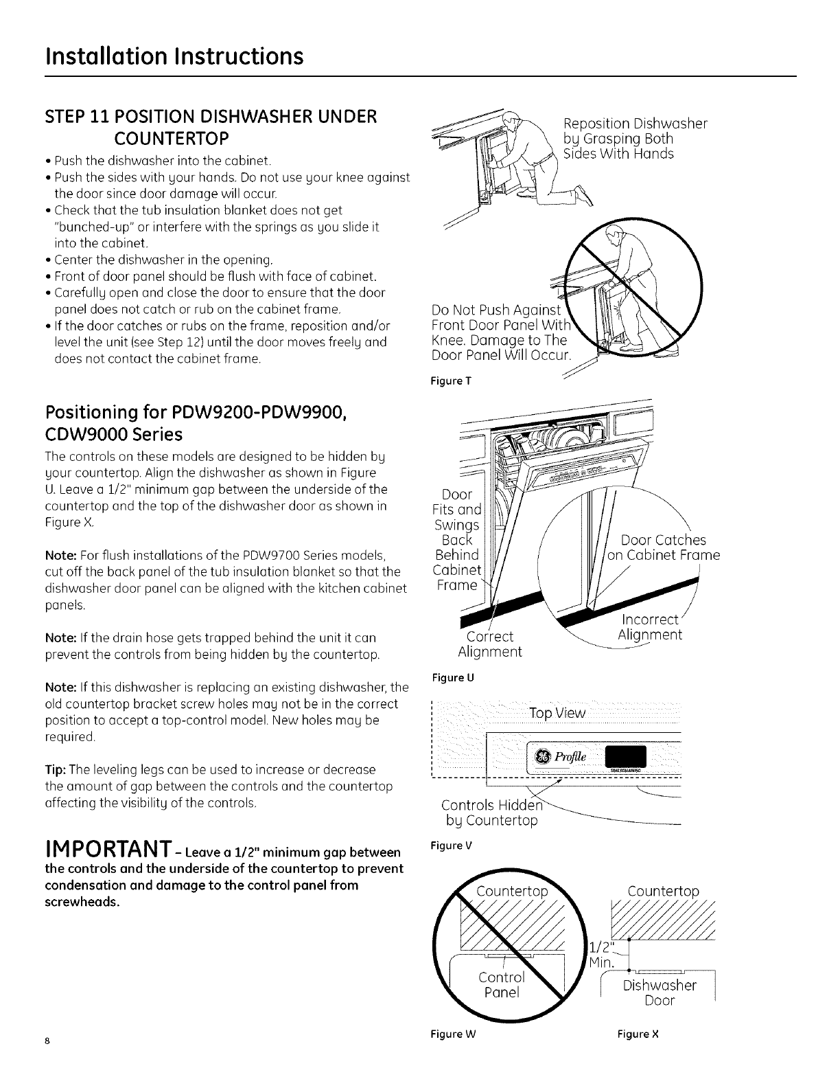
STEP 21 POSITION DISHWASHER UNDER
CO UNTE RTO P
• Push the dishwasher into the cabinet.
• Push the sides with gour hands. Do not use gour knee against
the door since door damage will occur.
• Check that the tub insulation blanket does not get
"bunched-up" or interfere with the springs as gou slide it
into the cabinet.
• Center the dishwasher in the opening.
• Front of door panel should be flush with face of cabinet.
• Carefullg open and close the door to ensure that the door
panel does not catch or rub on the cabinet frame.
• If the door catches or rubs on the frame, reposition and/or
level the unit (see Step 12) until the door moves freelg and
does not contact the cabinet frame.
Positioning for PDW9200-PDW9900,
CDW9000 Series
The controls on these models are designed to be hidden bg
gour countertop. Align the dishwasher as shown in Figure
U.Leave a 1/2" minimum gap between the underside of the
countertop and the top of the dishwasher door as shown in
Figure X.
Note: For flush installations of the PDW9700 Series models,
cut off the back panel of the tub insulation blanket so that the
dishwasher door panel can be aligned with the kitchen cabinet
panels.
Note: If the drain hose gets trapped behind the unit it can
prevent the controls from being hidden by the countertop.
Note: If this dishwasher is replacing an existing dishwasher, the
old countertop bracket screw holes may not be in the correct
position to accept a top-control model. New holes may be
required.
Tip: The leveling legs can be used to increase or decrease
the amount of gap between the controls and the countertop
affecting the visibility of the controls.
IMPORTANT- Leoveo1/2"minimumgopbetween
the controls ond the underside of the countertop to prevent
condensotion end damage to the control panel from
screwheods.
/<
Do Not Push Against_
Front Door PanelT_t#
Knee. Damage to The
Door Panel Will Occur.
Figure T
Reposition Dishwasher
_"_ , \ bg Grasping Both
With Hands
Door
Fits and
Swings
Back Door Catches
Behind in Cabinet Frame
Cabinet J
Frame
Correct
Alignment
Incorrect
Alignment
Figure U
,,'' Top view
,,"' e
Controls Hidden_ _
bg Countertop
Figure V
Countertop
Dishwasher
Door
8 Figure W Figure ×
Installation Instructions
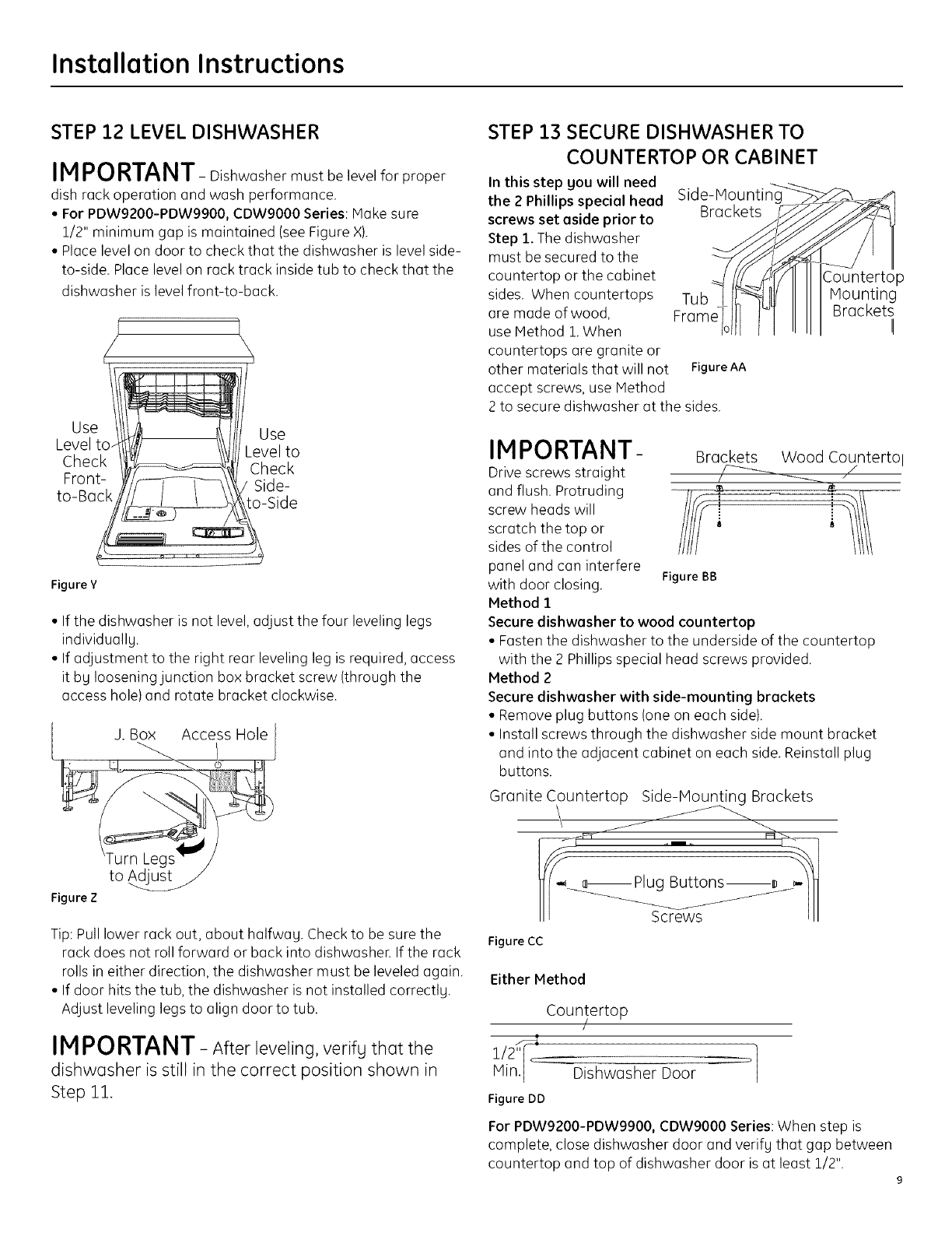
STEP 22 LEVEL DISHWASHER
IM PORTANT-Dishwasher must be levelforproper
dishrack operationand wash performance.
• For PDW9200-PDW9900, CDW9000 Series:Make sure
1/2"minimum gap ismaintained (seeFigureX).
• Place levelon door to check thatthe dishwasher islevelside-
to-side.Place levelon racktrackinsidetub to check thatthe
dishwasher islevelfront-to-back.
/\,
to-Ba! S,de
Figure Y
•If the dishwasher is not level, adjust the four leveling legs
individuallu.
• If adjustment to the right rear leveling leg is required, access
it by loosening junction box bracket screw {through the
access hole) and rotate bracket clockwise.
J. Box Access Hole
Figure Z
Tip: Pull lower rack out, about halfwag. Check to be sure the
rack does not roll forward or back into dishwasher. If the rack
rolls in either direction, the dishwasher must be leveled again.
• If door hits the tub, the dishwasher is not installed correctlg.
Adjust leveling legs to align door to tub.
IMPORTANT - After leveling, verifg that the
dishwasher is still in the correct position shown in
Step 11.
STEP 13 SECURE DISHWASHER TO
COUNTERTOP OR CABINET
In this step you will need
the 2 Phillips special head
screws set aside prior to
Step 1. The dishwasher
must be secured to the
countertop or the cabinet
sides. When countertops
are made of wood,
use Method 1 When
countertops are granite or
Side-Mountin_ -_
Brackets .f_
F Ub o
other materials that will not FigureAA
accept screws, use Method
2 to secure dishwasher at the sides.
Countertop
Mounting
Brackets II
IMPORTANT-
Drive screws straight
and flush. Protruding
screw heads will
scratch the top or
sides of the control
panel and can interfere
with door closing. FigureBB
Method 1
Secure dishwasher to wood countertop
• Fasten the dishwasher to the underside of the countertop
with the 2 Phillips special head screws provided.
Method 2
Secure dishwasher with side-mounting brackets
• Remove plug buttons (one on each side).
• Install screws through the dishwasher side mount bracket
and into the adjacent cabinet on each side. Reinstall plug
buttons.
Granite Countertop Si_Brackets
_ _ Plug Buttons _ _--_
III III
Brackets Wood Countertol
Figure CC
Either Method
Countertop
/
/
Min. I Dishwasher Door
Figure DD
For PDW9200-PDW9900, CDW9000 Series: When step is
complete, close dishwasher door and verifu that gap between
countertop and top of dishwasher door is at least 1/2".
Installation Instructions
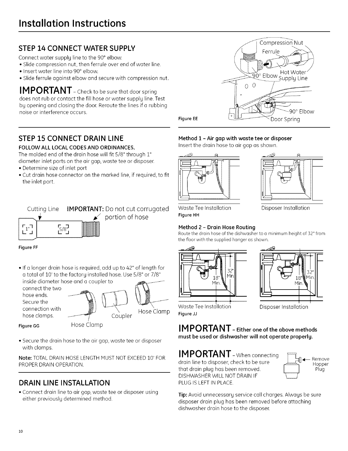
STEP 14 CONNECT WATER SUPPLY
Connect water supply line to the 90° elbow.
• Slide compression nut, then ferrule over end of water line.
• Insert water line into 90° elbow.
• Slide ferrule against elbow and secure with compression nut.
IN PORTANT- Check to be sure that door spring
does not rub or contact the fill hose or water supply line. Test
by opening and closing the door. Reroute the lines if a rubbing
noise or interference occurs.
Figure EE
Compression Nut
Ferrule
Hot Water
_0° Elbow Supply Line
o
\ Door Spring
STEP 3.5 CONNECT DRAIN LINE
FOLLOWALL LOCAL CODESAND ORDINANCES.
The molded end of the drain hose will fit 5/8" through 1"
diameter inlet ports on the air gap, waste tee or disposer.
• Determine size of inlet port
• Cut drain hose connector on the marked line, if required, to fit
the inlet port.
Cutting Line IMPORTANT: Do not cut corrugated
_/ portion of hose
Figure FF
connection with
hose clamps.
Figure GG
• If a longer drain hose is required, add up to 42" of length for
a total of 10' to the factory installed hose. Use 5/8" or 7/8"
inside diameter hose and a coupler to
connect the two
hose ends.
Secure the
Coupler
Hose Clamp
Hose Clamp
• Secure the drain hose to the air gap, waste tee or disposer
with clamps.
Note: TOTAL DRAIN HOSE LENGTH MUST NOT EXCEED 10' FOR
PROPER DRAIN OPERATION.
DRAIN LINE INSTALLATION
• Connect drain line to air gap, waste tee or disposer using
either previously determined method.
Method 1 - Air gap with waste tee or disposer
Insert the drain hose to air gap as shown.
Waste Tee Installation
Figure HH
Disposer Installation
Method 2 - Drain Hose Routing
Route the drain hose of the dishwasher to a minimum height of 32" from
the floor with the supplied hanger as shown.
_ j"_a
Figure JJ
Disposer Installation
IMPORTANT- Eitherone oftheabovemethods
must be used or dishwasher will not operate properly.
IMPORTANT- Whenconnecting
drain line to disposer, check to be sure
that drain plug has been removed.
DISHWASHERWILL NOTDRAINIF
PLUGIS LEFTIN PLACE.
[_ Remove
Hopper
Plug
Tip: Avoid unnecessary servicecallcharges.Always be sure
disposerdrainplug has been removed beforeattaching
dishwasher drainhose to the disposeE
io

Installation Instructions
STEP 16 CONNECT POWER SUPPLY
Skip this step if dishwasher is equipped with power cord.
Verifg that power is turned off at the source.
If a power cord with plug is used, proceed to Step 16.
• Locate the junction box cover within the user bog.
• Secure house wiring to the back of the junction box with a
strain relief.
• Locate the three dishwasher wires, {white, black and green)
with stripped ends. Insert dishwasher wires through the small
hole in the junction box. Use wire nuts to connect incoming
ground to green, white to white and black to black.
• Install the junction box cover. Check to be sure that wires ore
not pinched under the coven
Locate Insert Power
Junchon Box Cord Wires Thru \ _,\\_ )
CoverWith,n Strain Relief X _'___-_"_ /
User Bog and Tighten _ v_
.......... I hite
BCheckThatWhite, Blackand _
GreenDishwasherWiresAreThreaded _ )b
Thru SmallHolein Bracket D ///
UseULListed
Wire Nuts
Figure KK
If house wiring is not 2-wire with ground, a
ground must be provided bg the installer.
When house wiring is aluminum, be sure to
use UL Listed anti-oxidant compound and
aluminum- to-copper connectors
STEP 17 PRETEST CHECK LIST
Review this list after installing gour dishwasher to
avoid charges for a service call that is not covered bg gour
warrantg.
[] Check to be sure power is OFF.
[] Open door and remove all foam and paper packaging.
[] Locate the Owner's Manual in the user bag.
[] Read the Owner's Hanual for operating instructions.
[] Check door opening and closing. If door does not open and
close freelg, check for proper routing of spring cable over
pulleg. See Step 2, Figure H. If door drops or closes when
released, adjust spring tension.
[] Check to be sure that wiring is secure under the dishwasher,
not pinched or in contact with door springs or other
components. See Steps 9 and 10.
[] Check door alignment with tub. If door hits tub, level
dishwasher. See Step 12.
[] Pull lower rack out, about halfwag. Check to be sure it does
not roll back or forward on the doon If the rack moves,
adjust leveling legs. SeeStep 12.
[] Check door alignment with cabinet. If door hits cabinet,
reposition or relevel dishwashe_ SeeSteps 11, 12 and 13.
[] Check that door spring does not contact water line, fill hose,
wiring or other components. See Step 14.
[] Verifu water supplu and drain lines are not kinked or in
contact with other components. Contact with motor or
dishwasher frame could cause noise. SeeSteps 7 and 9.
[] Turn on the sink hot water faucet and verifu water
temperature. Incoming water temperature must
be between 120°Fand 150°R A minimum of 120°F
temperature is required for best wash performance. See
"Prepare Hot Water Line,"page 5.
[] Add 2 quarts of water to the bottom of the dishwasher to
lubricate the pump seal.
[] Turn on water supplu. Check for leaks. Tighten connections
if needed.
[] Remove protective film if present from the control panel
and doon
[] Avoid service call charges bg ensuring there is an air gap
or drain hose routed through the required 32" minimum
height.
Installation Instructions
STEP 18 DISHWASHER WET TEST
[] Turn on power supply (or plug power cord into outlet,
if equipped).
[] Start the unit to check for leaks.
PDW8200-PDW8900 Series:
- Latch door
- Push RINSEONLYpad
- Push START/RESETpad one time
PDW9200-PDW9900, CDW9000 Series:
- Push RINSEONLYpad
- Push START/RESETpad one time
- Close door
[] Check to be sure that water enters the dishwasher. If water
does not enter the dishwasher, check to be sure that water
and power are turned on. _
[] Check for leaks under the dishwasheE If a leak is found, turn
off power supply, then tighten connections. Restore power
after leak is corrected. FigureLL
[] Check for leaks around the door. A leak around the door
could be caused by door rubbing or hitting against
adjacent cabinet. Reposition the dishwasher if necessary.
See Step 11.
[] The dishwasher will drain and turn off about 5 minutes after
it was started. Check drain lines. If leaks are found, turn off
power at the breaker and correct plumbing as necessary.
Restore power after corrections are made. See Step 8
and 15.
[] Open dishwasher door and make sure most of the water
has drained. If not, check that disposer plug has been
removed and/or air gap is not plugged. SeeStep 15. Also
check drain line for kinking.
[] Run the dishwasher through another "Rinse Only" cycle.
Check for leaks and correct if required.
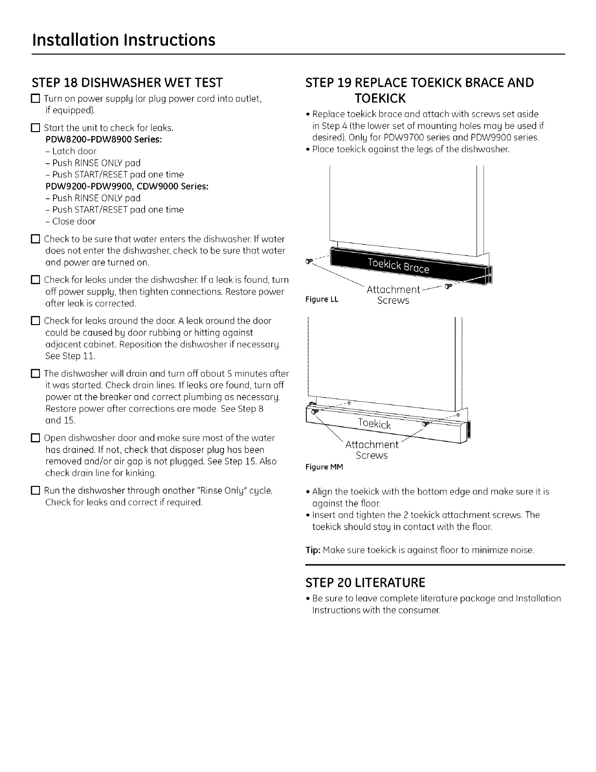
STEP 19 REPLACE TOEKICK BRACE AND
TOEKICK
• Replace toekick brace and attach with screws set aside
in Step 4 (the lower set of mounting holes may be used if
desired). Only for PDW9700 series and PDW9900 series.
• Place toekick against the legs of the dishwasher.
Attachment _
Screws
Screws
Figure MM
• Align the toekick with the bottom edge and make sure it is
against the flooE
• Insert and tighten the 2 toekick attachment screws. The
toekick should stag in contact with the floor.
Tip: Make sure toekick is against floor to minimize noise.
STEP 20 LITERATURE
• Besure to leave complete literature package and Installation
Instructions with the consumer.

SPECIFICATIONS SUBJECT TO CHANGE WITHOUT NOTICE
GE Consumer & Industrial
General Electric Company
Louisville, Kentucky 40225
ge.com
© 2007 General Electric Company
Pub. No. 31-30233
Dwg. No. 206C1559P172
ND 07D-221914/07}
