GE CVM1790SS1SS User Manual MICROWAVE Manuals And Guides 1108784L
User Manual: GE CVM1790SS1SS CVM1790SS1SS GE MICROWAVE - Manuals and Guides View the owners manual for your GE MICROWAVE #CVM1790SS1SS. Home:Kitchen Appliance Parts:GE Parts:GE MICROWAVE Manual
Open the PDF directly: View PDF ![]() .
.
Page Count: 48
Installation
Instructions Above the
Cooktop Oven
PVM1790
CVM1790
IQuestions? Cull 800.GE.CARES (800.432.2737) or visitourWebsiteat: GEAppliunces.com I
BEFOREYOU BEGIN
Read these instructions completely and carefully.
• IMPORTANT - Sovethese
instructionsforIo¢oiinspector'suse
• IMPORTANT - Observeo,,
governing codes ond ordinonces
• Note to Installer- Be sureto leovethese
instructionswiththe Consumer
Note to Consumer - Keepthese instructions
for future reference.
Skill level - Instollotion of this opplionce requires bosic
mechonicol ond electricol skills.
Proper instollotion is the responsibility of the instoller.
Product foilure due to improper instollotion is not
covered under the Worronty.
LA SECClON EN ESPANOL
EMPIEZAEN LA P,a,GINA 25.
READ CAREFULLY.
KEEP THESE INSTRUCTIONS.
49-40654
MFL59060904
Installation Instructions
CONTENTS
General information
Important Safety Instructions ........................................3
Electrical Requirements ..................................................3
Hood Exhaust ................................................................4, 5
Damage - Shipment/Installation ..................................6
Parts Included ...................................................................6
Tools You Will Need .........................................................7
Mounting Space ................................................................7
Step-by-step installation guide
Placement of Mounting Plate .................................. 8-10
Removing the Mounting Plate .............................8
Finding the Wall Studs..........................................8
Determining Wall Plate Location ........................9
Aligning the Wall Plate .......................................10
Installation Types ....................................................11-22
[_ Outside Top ....................................
Exhaust 12-14
Attach Mounting Plate to Wall .................12
Preparation of Top Cabinet.......................13
Assemble and Install Adaptor ..................13
Mount the Oven...................................13, 14
Adjust the Exhaust Adaptor ......................14
Connecting Ductwork ................................14
[_i_ Outside .................................. 15-18
Back Exhaust
Preparing Rear Wall for
Outside Back Exhaust................................15
Attach Mounting Plate to Wall .......... 15, 16
Preparation of Top Cabinet.......................16
Adapting Blower for Outside
Back Exhaust ..........................................16, 17
Mount the Oven..........................................18
[_ Recirculatinc .................................................19-22
Attach Mounting Plateto Wall ................19
Preparationof Top Cabinet......................19
Adapting Blower
forRecirculation..................................20,21
Mount the Oven ...................................21,22
Installingthe Charcoal Filter....................22
Before You Use Your Oven ..........................................23
Secci6n en Espa_ol .................................................25-47
Installation Instructions
IMPORTANT SAFETY INSTRUCTIONS
A qualified electrician must perform a ground continuity
check on the wall receptacle before beginning the
installation to ensure that the outlet box is properly
grounded. If not properly grounded, or if the wall
receptacle does not meet electrical requirements noted
(under ELECTRICALREQUIREMENTS),a qualified electrician
should be employed to correct any deficiencies.
WARNING:
Risk of Electric Shock.
Can cause injury or death:
Remove house fuse or
open circuit breaker before
beginning installation to avoid
severe or fatal shock injury.
A,,,^n,,,,,,,,-
J_W/_nl_l I I_1_._: Risk of Electric Shock.
Can cause injury or death: THIS APPLIANCEMUSTBE
PROPERLYGROUNDEDto avoid severe or fatal shock.
120 V Models
_su_l P_Pt_r
beforeuse
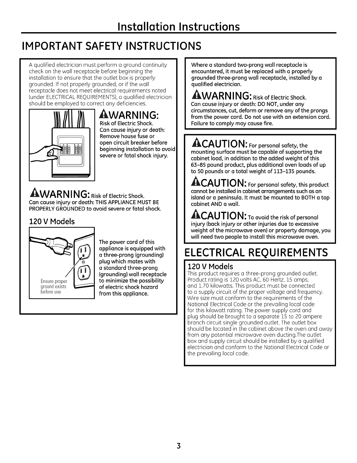
The power cord of this
appliance is equipped with
a three-prong (grounding)
plug which mates with
a standard three-prong
(grounding) wall receptacle
to minimize the possibility
of electric shock hazard
from this appliance.
Where a standard two-prong wall receptacle is
encountered, it must be replaced with a properly
grounded three-prong wall receptacle, installed by a
qualified electrician.
kWARN ING: RiskofElectricShock.
Can cause injury or death: DO NOT, under any
circumstances, cut, deform or remove any of the prongs
from the power cord. Do not use with an extension cord.
Failure to comply may cause fire.
Ar-^, ,-r,,-,_,
ml_.,/'_U/l_/l_l: For personal safety, the
mounting surface must be capable of supporting the
cabinet load, in addition to the added weight of this
63-85 pound product, plus additional oven loads of up
to 50 pounds or a total weight of 113-135 pounds.
kCAUTION: Forpersona,sofety,thisproduct
cannot be installed in cabinet arrangementssuch asan
island or openinsula. It must be mounted to BOTHa top
cabinet AND awall.
CAUTION: Toavoidtheriskofpersona,
inJury (back inJury or other inJuries due to excessive
weight of the microwave oven) or property damage, you
will need two people to install this microwave oven.
ELECTRICAL REQUIREMENTS
120 V Models
This product requires a three-prong grounded outlet.
Product rating is 120 volts AC, 60 Hertz, 15 amps,
and 1.70 kilowatts. This product must be connected
to a supply circuit of the proper voltage and frequency.
Wire size must conform to the requirements of the
National Electrical Code or the prevailing local code
for this kilowatt rating. The power supply cord and
plug should be brought to a separate 15 to 20 ampere
branch circuit single grounded outlet. The outlet box
should be located in the cabinet above the oven and away
from any potential microwave oven ducting.The outlet
box and supply circuit should be installed by a qualified
electrician and conform to the National Electrical Code or
the prevailing local code.
3
Installation Instructions
HOOD EXHAUST
NOTE: Reed these next two pages only if you plan to vent your exhaust to the outside.
If you plan to recirculate the air back into the room, proceed to page 6.
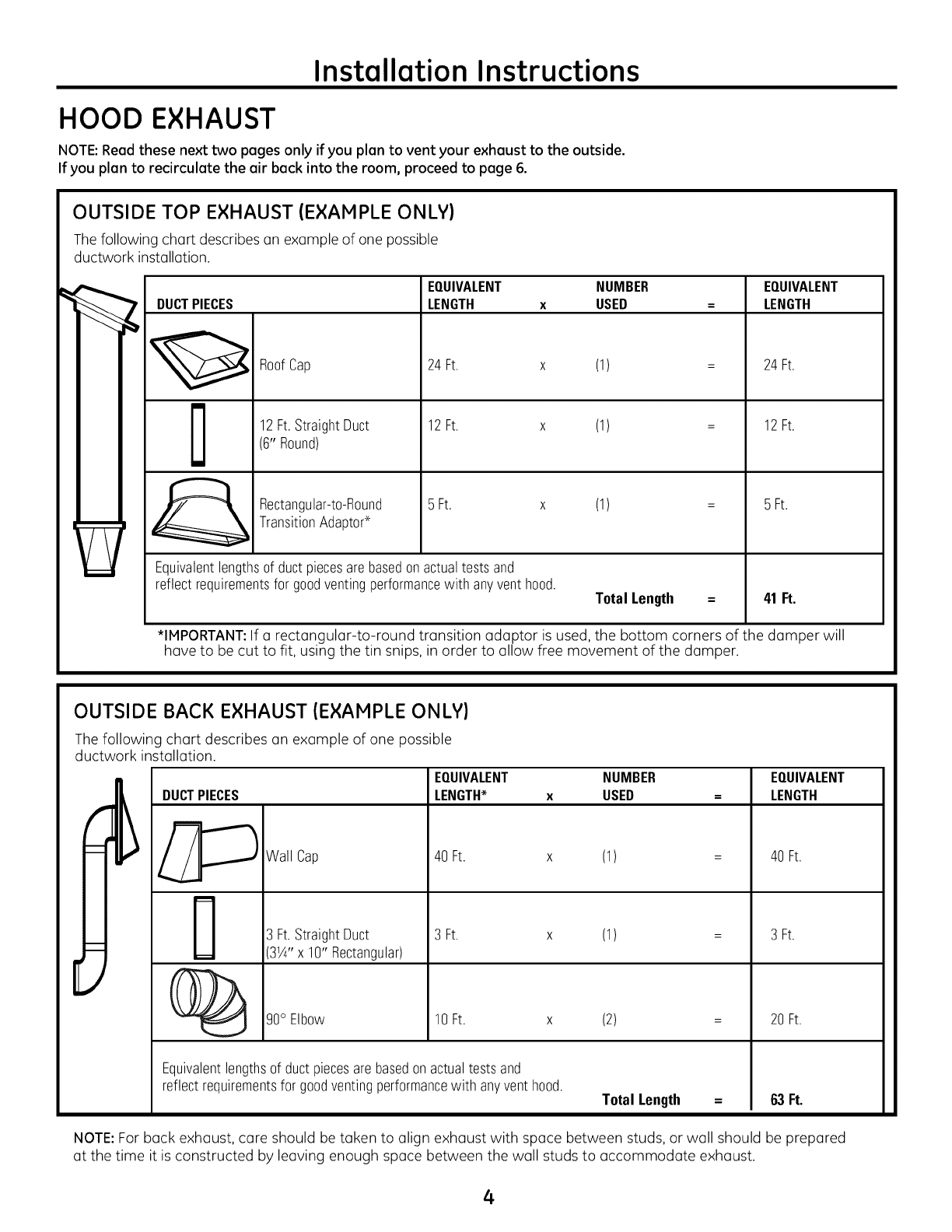
OUTSIDE TOP EXHAUST (EXAMPLE ONLY)
The following chart describes an example of one possible
ductwork installation.
_Roof Cap
12Ft.StraightDuct
(6" Round)
Rectangular-to-Round
TransitionAdaptod
EQUIVALENT NUMBER EQUIVALENT
LENGTH xUSED = LENGTH
24Ft.
12Ft.
5 Ft. x (1)
Equivalentlengthsof ductpiecesarebasedonactualtests and
reflect requirementsfor goodventingperformancewith anyventhood. Total Length =
24Ft.
12Ft.
5 Ft.
41 Ft.
*IMPORTANT:If a rectangular-to-round transition adaptor is used, the bottom corners of the damper will
have to be cut to fit, using the tin snips, in order to allow free movement of the damper.
OUTSIDE BACK EXHAUST (EXAMPLE ONLY)
The following chart describes an example of one possible
ductwork installation.
E
DUCTPIECES
Wall Cap
Ft.StraightDuct
3W' x 10" Rectangular)
90° Elbow
EQUIVALENT NUMBER EQUIVALENT
LENGTH_ x USED = LENGTH
40Ft. x (1)
3 Ft. x (1)
10 Ft. x (2)
Equivalentlengthsof ductpiecesarebasedonactualtestsand
reflect requirementsfor goodventingperformancewith anyvent hood. Total Length =
40Ft.
3 Ft.
20Ft.
63 Ft.
NOTE: For back exhaust, care should be taken to align exhaust with space between studs, or wall should be prepared
at the time it is constructed by leaving enough space between the wall studs to accommodate exhaust.
4
Installation Instructions
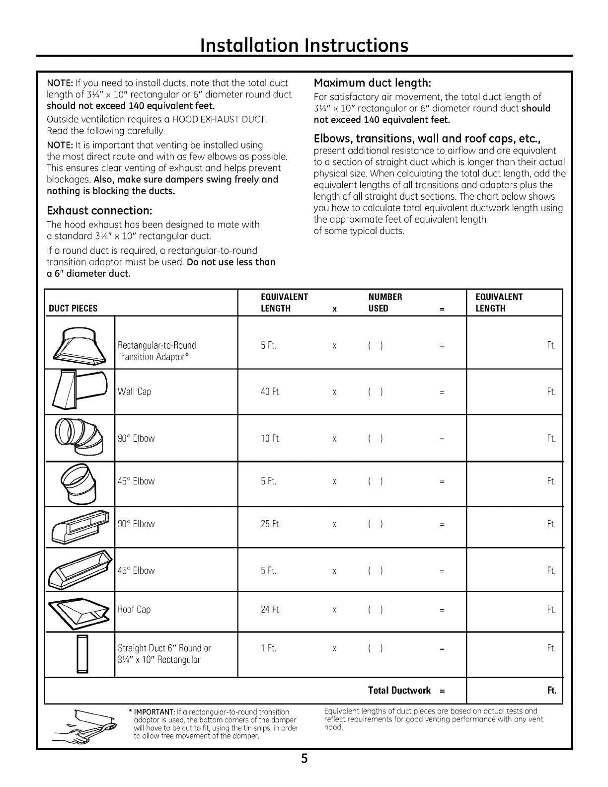
NOTE: If you need to install ducts, note that the total duct
length of 3VJ' x 10" rectangular or 6" diameter round duct
should not exceed 140 equivalent feet.
Outside ventilation requires a HOODEXHAUSTDUCT.
Read the following carefully.
NOTE: It is important that venting be installed using
the most direct route and with as few elbows as possible.
This ensures clear venting of exhaust and helps prevent
blockages. Also, make sure dampers swing freely and
nothing is blocking the ducts.
Exhaust connection:
The hood exhaust has been designed to mate with
a standard 3½" x 10" rectangular duct.
If a round duct is required, a rectangular-to-round
transition adaptor must be used. Do not use less than
a 6" diameter duct.
Maximum duct length:
For satisfactory air movement, the total duct length of
3½" x 10" rectangular or 6" diameter round duct should
not exceed 140 equivalent feet.
Elbows, transitions, wall and roof caps, etc.,
present additional resistance to airflow and are equivalent
to a section of straight duct which is longer than their actual
physical size. When calculating the total duct length, add the
equivalent lengths of all transitions and adaptors plus the
length of all straight duct sections. The chart below shows
you how to calculate total equivalent ductwork length using
the approximate feet of equivalent length
of some typical ducts.
EQUIVALENT NUMBER EQUIVALENT
DUCTPIECES LENGTH xUSED = LENGTH
Rectangular-t0-R0und 5 Ft. x ( ) = Ft.
TransitionAdapt0€_
_ Wall Cap 40 Ft. x ( ) = Ft.
(_ g0° Elbow 10Ft. x ( ) = Ft.
45° Elbow 5 Ft. x ( ) = Ft.
g0° Elbow 25 Ft. x ( ) = Ft.
45°EIb0w 5Ft. x ( ) = Ft.
RoofCap 24 Ft. x ( ) = Ft.
StraightDuct6" Roundor 1 Ft. x ( ) = Ft.
3W'x 10" Rectangular
Total Ductwork = Ft.
* IMPORTANT:If a rectangular-to-round transition Equivalent lengths of duct pieces are based on actual tests and
adaptor is used, the bottom corners of the damper reflect requirements for good venting performance with any vent
will have to be cut to fit, using the tin snips, in order hood.
to allow free movement of the damper.
5
Installation Instructions
DAMAGE- SHIPMENT/
INSTALLATION
• If the unit is domoged in shipment, return
the unit to the store in which it was bought for
repair or replacement.
• If the unit is domoged by the customer, repair or
replacement is the responsibility of the customer.
• If the unit is domoged by the instoller (if other than
the customer), repair or replacement must
be made by arrangement between customer
and installer.
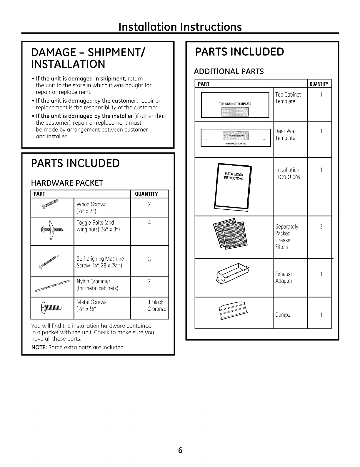
PARTS INCLUDED
HARDWARE PACKET
PART
S
J
WoodScrews
(Y4"x 2")
ToggleBolts(and
wing nuts)(1¼,x 3")
Self-aligningMachine
Screw(W'-28 x 2%")
NylonGrommet
(for metalcabinets)
Metal Screws
(1/8" X 1/2")
QUANTITY
1black
2bronze
You will find the installation hardware contained
in a packet with the unit. Check to make sure you
have all these parts.
NOTE:Some extra parts are included.
PARTS INCLUDED
ADDITIONAL PARTS
PART
TOPCABINETTEMPLATE
......
® REARWtL!_EMPLA_U
INSTALLATION
INSTRUCTIONS
Top Cabinet
Template
RearWall
Template
Installation
Instructions
Separately
Packed
Grease
Filters
Exhaust
Adaptor
Damper
QUANTITY
1
1
1
2
1
1
6
Installation Instructions
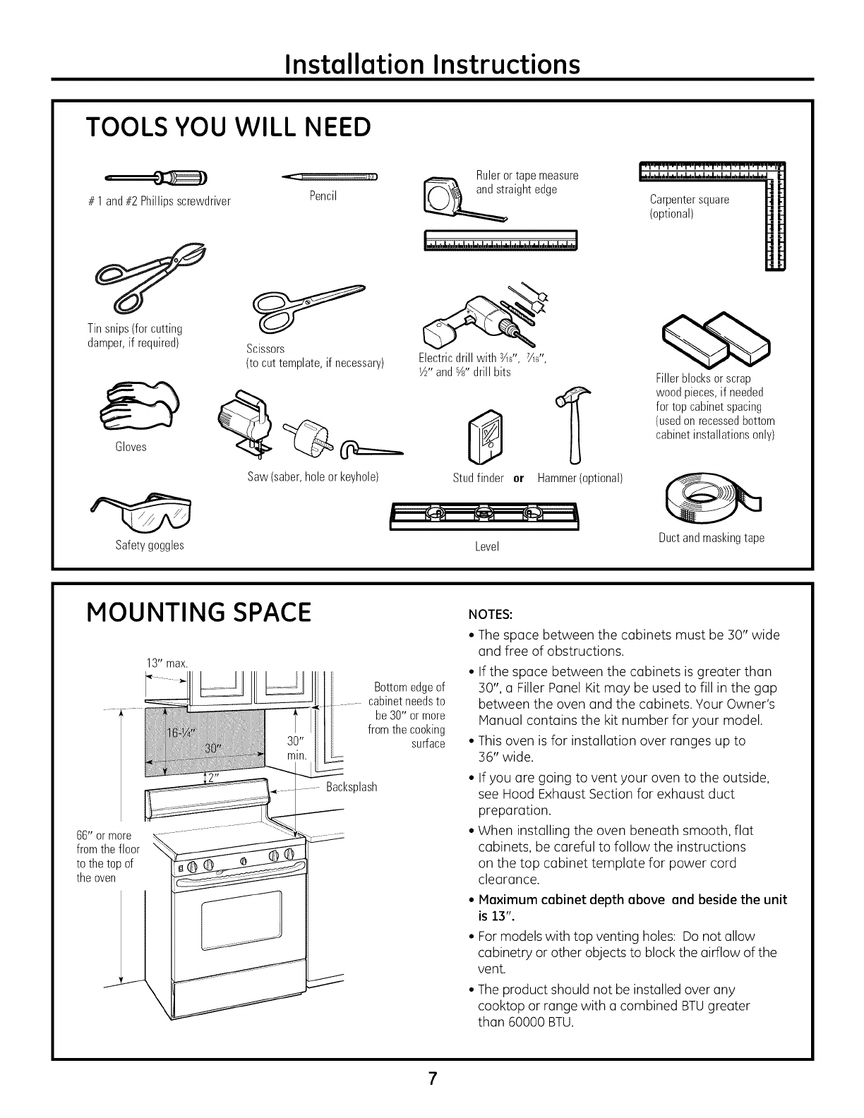
TOOLS YOU WILL NEED
# 1 and#2 Phillipsscrewdriver
Tinsnips(forcutting
damper,if required)
Gloves
Safetygoggles
Pencil
Scissors
(tocuttemplate,if necessary)
Saw(saber,holeorkeyhole)
Ruleror tapemeasure
aightedge
Electricdrillwith¾s",7½d',
_½"and%" drillbits
Studfinder or Hammer(optional)
Level
Carpentersquare
(optional)
Fillerblocksor scrap
woodpieces,if needed
for top cabinetspacing
(usedonrecessedbottom
cabinetinstallationsonly)
Ductandmaskingtape
MOUNTING SPACE
66" or more
fromthefloor
tothetopof
theoven
Bottomedgeof
cabinetneedsto
be30" or more
fromthe cooking
surface
Backsplash
NOTES:
• The space between the cabinets must be 30" wide
and free of obstructions.
• If the space between the cabinets is greater than
30", a Filler Panel Kit may be used to fill in the gap
between the oven and the cabinets. Your Owner's
Manual contains the kit number for your model.
• This oven is for installation over ranges up to
36" wide.
• If you are going to vent your oven to the outside,
see Hood Exhaust Section for exhaust duct
preparation.
• When installing the oven beneath smooth, flat
cabinets, be careful to follow the instructions
on the top cabinet template for power cord
clearance.
• Maximum cabinet depth above and beside the unit
is 13".
•For models with top venting holes: Do not allow
cabinetry or other objects to block the airflow of the
vent.
• The product should not be installed over any
cooktop or range with a combined BTUgreater
than 60000 BTU.
Installation Instructions
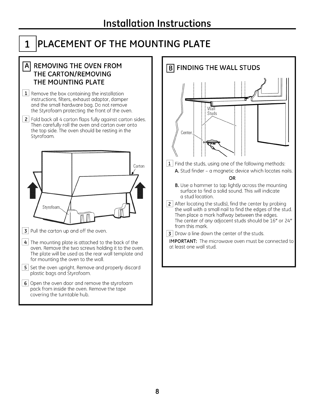
I-- PLACEMENT OF THE MOUNTING PLATE
E]REMOVING THE OVEN FROM
THE CARTON/REMOVING
THE MOUNTING PLATE
%
[]
Remove the box containing the installation
instructions, filters, exhaust adaptor, damper
and the small hardware bag. Do not remove
the Styrofoam protecting the front of the oven.
Fold back all 4 carton flaps fully against carton sides.
Then carefully roll the oven and carton over onto
the top side. The oven should be resting in the
Styrofoam.
%
%
%
Pullthe carton up and off the oven.
The mounting plate is attached to the back of the
oven. Remove the two screws holding it to the oven.
The plate will be used as the rear wall template and
for mounting the oven to the wall.
Set the oven upright. Remove and properly discard
plastic bags and Styrofoam.
Open the oven door and remove the styrofoam
pack from inside the oven. Remove the tape
covering the turntable hub.
FINDING THE WALL STUDS
Center_
Studs
[_ Find the studs, using one of the following methods:
A. Stud finder - a magnetic device which locates nails.
OR
B. Use a hammer to tap lightly across the mounting
surface to find a solid sound. This will indicate
a stud location.
[_ After locating the stud(s),find the center by probing
the wall with a small nail to find the edges of the stud.
Then place a mark halfway between the edges.
The center of any adjacent studs should be 16" or 24"
from this mark.
[_ Draw u line down the center of the studs.
IMPORTANT: The microwave oven must be connected to
at least one wall stud.
8
Installation Instructions
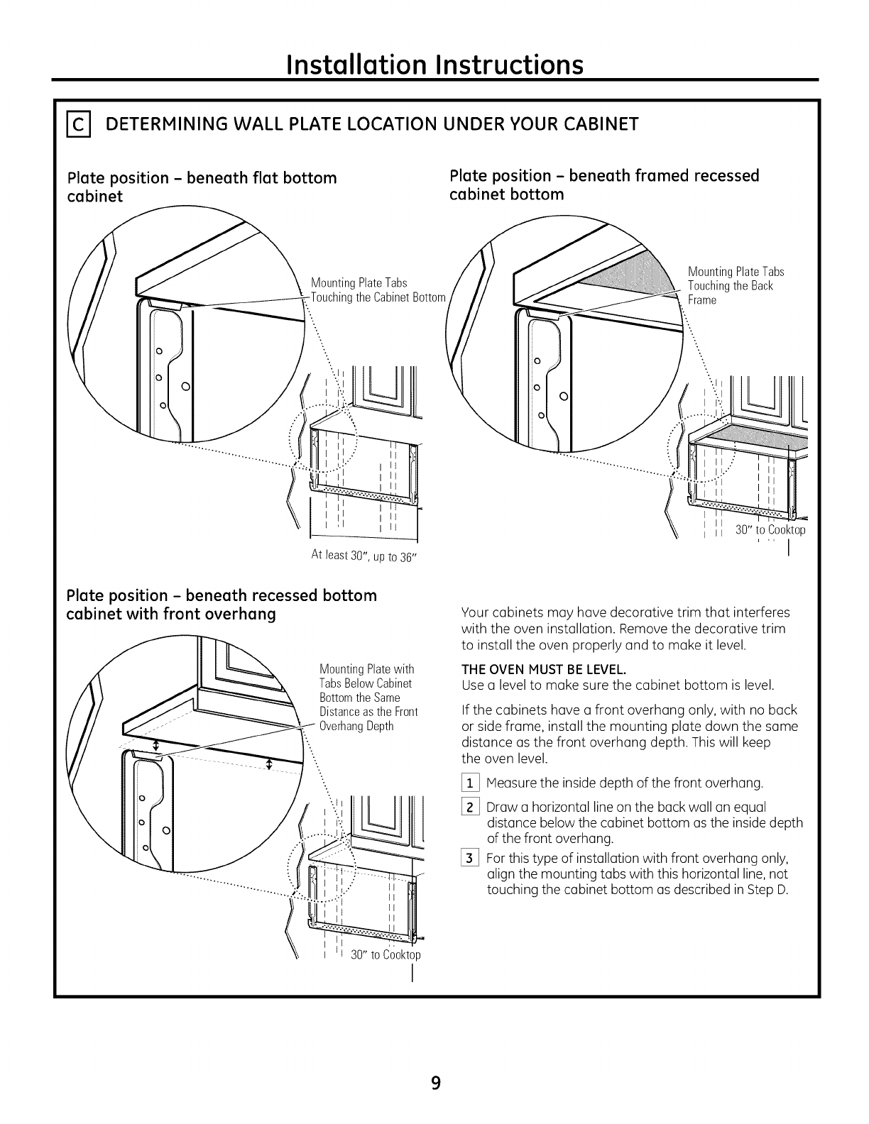
_'1 DETERMINING WALL PLATE LOCATION UNDER YOUR CABINET
Plate position - beneath flat bottom
cabinet
Plate position - beneath framed recessed
cabinet bottom
Ol
MountingPlateTabs
the CabinetBottom
At least 30", up to 36"
MountingPlateTabs
Touchingthe Back
Frame
II
II 30"to Cooktop
i,, j
Plate position - beneath recessed bottom
cabinet with front overhang
O
O
MountingPlatewith
TabsBelow Cabinet
Bottomthe Same
Distanceas the Front
OverhangDepth
l
30" to Cooktop
I
Your cabinets may have decorative trim that interferes
with the oven installation. Remove the decorative trim
to install the oven properly and to make it level.
THE OVEN MUST BE LEVEL.
Use a level to make sure the cabinet bottom is level.
If the cabinets have a front overhang only, with no back
or side frame, install the mounting plate down the same
distance as the front overhang depth. This will keep
the oven level.
[_ Measure the inside depth of the front overhang.
[_ Draw a horizontal line on the back wall an equal
distance below the cabinet bottom as the inside depth
of the front overhang.
[_ For this type of installation with front overhang only,
align the mounting tabs with this horizontal line, not
touching the cabinet bottom as described in Step D.
9
Installation Instructions
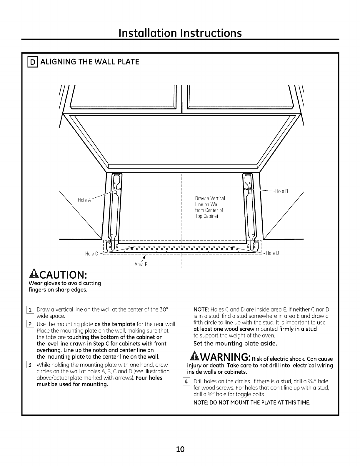
r-_ ALIGNING THE WALL PLATE
Hole
I
I
HoleC
,CAUTION:
Wear gloves to avoid cutting
fingers on sharp edges.
[_ Draw a vertical line on the wall at the center of the 30"
wide space.
[_ Usethe mounting plate as the template for the rear wall.
Placethe mounting plate on the wall, making sure that
the tabs are touching the bottom of the cabinet or
the level line drawn in Step C for cabinets with front
overhang. Line up the notch and center line on
the mounting plate to the center line on the wall.
[_3 While holding the mounting plate with one hand, draw
circles on the wall at holes A, B,C and D (see illustration
above/actual plate marked with arrows). Four holes
must be used for mounting.
NOTE: Holes C and D are inside area E.If neither C nor D
is in astud, find astud somewhere in area Eand draw a
fifth circle to line up with the stud. It is important to use
at least one wood screw mounted firmly in a stud
to support the weight of the oven.
Set the mounting plate aside.
WA RNIN G:Riskofelectricshock.Cancause
injury or death. Take care to not drill into electrical wiring
inside walls or cabinets.
[_ Drill holes on the circles. If there is astud, drill asA6"hole
for wood screws. For holes that don't line up with a stud,
drill a %" hole for toggle bolts.
NOTE:DO NOTMOUNTTHEPLATEAT THISTIME.
10
Installation Instructions
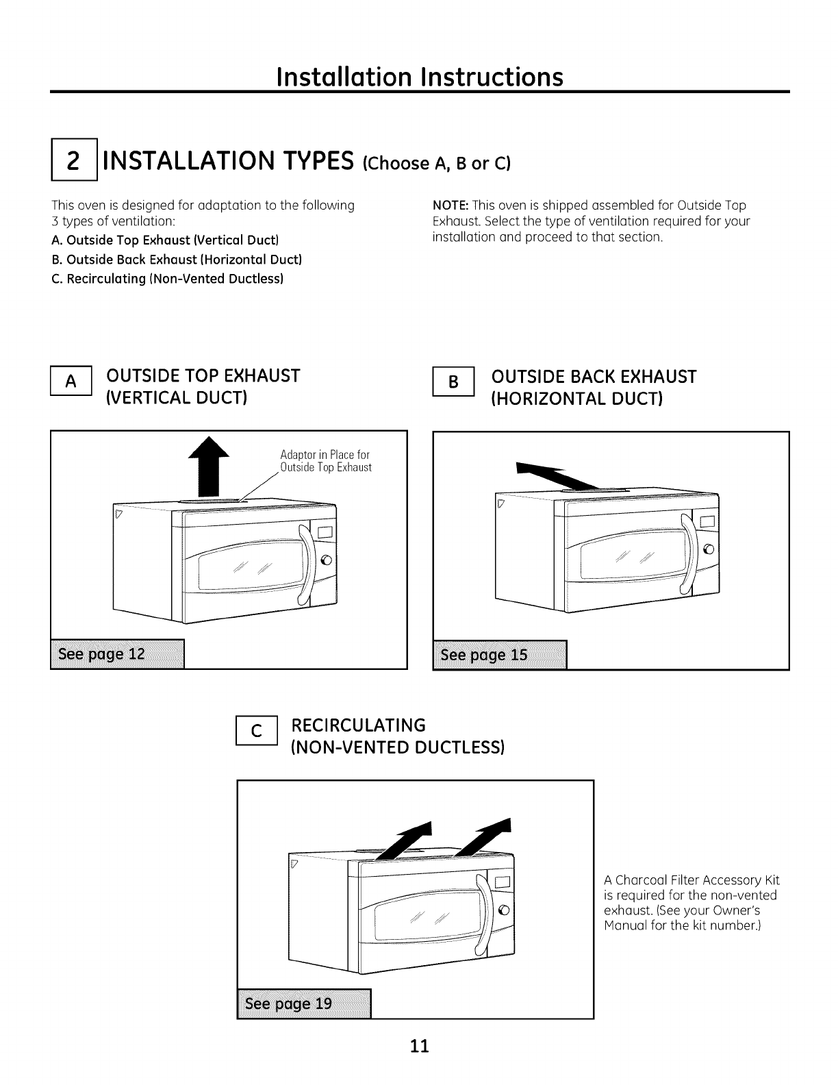
INSTALLATION TYPES
This oven is designed for adaptation to the following
:3 types of ventilation:
A. Outside Top Exhaust {Vertical Duct}
B. Outside Back Exhaust {Horizontal Duct}
C. Recirculating {Non-Vented Ductless}
(Choose A, B or C)
NOTE:This oven is shipped assembled for Outside Top
Exhaust. Select the type of ventilation required for your
installation and proceed to that section.
OUTSIDE TOP EXHAUST
(VERTICAL DUCT) _1 UTSIDE BACK EXHAUST
(HORIZONTAL DUCT)
IAdaptorin Placefor
OutsideTopExhaust
_1 RECIRCULATING
(NON-VENTED DUCTLESS)
A Charcoal Filter Accessory Kit
is required for the non-vented
exhaust. (Seeyour Owner's
Manual for the kit number.)
11
Installation Instructions
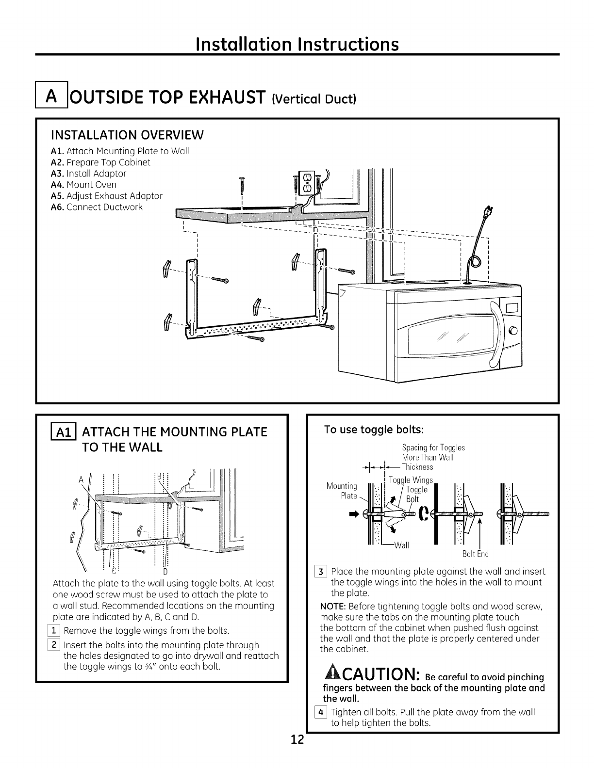
I- OUTSIDE TOP EXHAUST (Vertical Duct)
INSTALLATION OVERVIEW
At. Attach Mounting Plate to Wall
A2. Prepare Top Cabinet
A3. Install Adaptor
A4. Mount Oven
A5. Adjust Exhaust Adaptor
A6. Connect Ductwork
I
I
I
I
I I
I
I
I
I
I-_ ATTACH THE MOUNTING PLATE
TO THE WALL
A
D
Attach the plate to the wall using toggle bolts. At least
one wood screw must be used to attach the plate to
a wall stud. Recommended locations on the mounting
plate are indicated by A, B,C and D.
[_ Remove the toggle wings from the bolts.
[_ Insert the bolts into the mounting plate through
the holes designated to go into drywall and reattach
the toggle wings to sA"onto each bolt.
12
To use toggle bolts:
Mounting
SpacingforToggles
MoreThanWall
-_1_-_!_- Thickness
i ToggleWings.
BoltEnd
[_ Place the mounting plate against the wall and insert
the toggle wings into the holes in the wall to mount
the plate.
NOTE: Before tightening toggle bolts and wood screw,
make sure the tabs on the mounting plate touch
the bottom of the cabinet when pushed flush against
the wall and that the plate is properly centered under
the cabinet.
A,,-^, ,T,,-,_,
LIt, L,/_U/IUI_I: Be careful to avoid pinching
fingers between the back of the mounting plate and
the wall.
[_ Tighten all bolts. Pull the plate away from the wall
to help tighten the bolts.
Installation Instructions
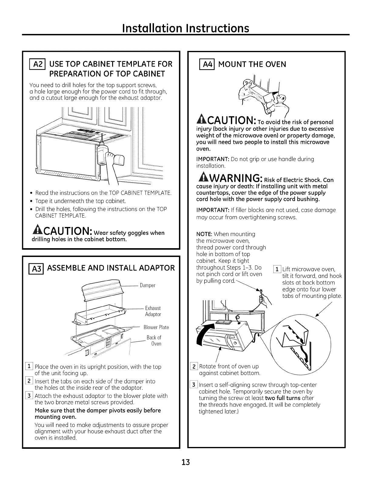
I--_"1 USE TOP CABINET TEMPLATE FOR
PREPARATION OF TOP CABINET
You need to drill holes for the top support screws,
u hole large enough for the power cord to fit through,
and u cutout large enough for the exhaust adaptor.
• Read the instructions on the TOP CABINETTEMPLATE.
• Tape it underneath the top cabinet.
• Drill the holes, following the instructions on the TOP
CABINETTEMPLATE.
A,-,^, ,T,,-,_,
JI_%,/_U/I _.Jl_l : Wear safety goggles when
drilling holes in the cabinet bottom.
ASSEMBLE AND INSTALL ADAPTOR
Damper
,_E ....... Exhaust
Adaptor
i BlowerPlate
Backof
__L_I Oven
[_3 Place the oven in its upright position, with the top
of the unit facing up.
[_3 Insert the tubs on each side of the dumper into
the holes at the inside rear of the adaptor.
[_3 Attach the exhaust adaptor to the blower plate with
the two bronze metal screws provided.
Make sure that the damper pivots easily before
mounting oven.
You will need to make adjustments to assure proper
alignment with your house exhaust duct after the
oven is installed.
r_S MOUNT THE OVEN
CAUTI riskofpersonal
injury (back injury or other injuries due to excessive
weight of the microwave oven) or property damage,
you will need two people to install this microwave
oven.
IMPORTANT: Do not grip or use handle during
installation.
J;lWl_l_l_l I I_1_._: Risk of Electric Shock. Can
cause injury or death: If installing unit with metal
countertops, cover the edge of the power supply
cord hole with the power supply cord bushing.
IMPORTANT: If filler blocks are not used, case damage
may occur from overtightening screws.
NOTE:When mounting
the microwave oven,
thread power cord through
hole in bottom of top
cabinet. Keep it tight
throughout Steps 1-3. Do
not pinch cord or lift oven
by pulling
[] Lift microwave oven,
tilt it forward, and hook
slots at back bottom
edge onto four lower
tabs of mounting plate.
[_3 Rotate front of oven up
against cabinet bottom.
[_3 Insert a self-aligning screw through top-center
cabinet hole. Temporarily secure the oven by
turning the screw at least two full turns after
the threads have engaged. (It will be completely
tightened later.)
13
Installation Instructions
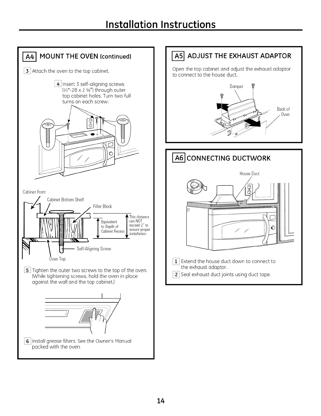
I--_I MOUNT THE OVEN (continued)
[_ Attach the oven to the top cabinet.
[_ Insert 3self-aligning screws
(_"-28 x 2 s_,,)through outer
top cabinet holes. Turn two full
turns on each screw.
CabinetFront
CabinetBottomShelf
FillerBlock
,Thisdistance
-_quivalent canNOT
I to Depthof | exceed2" to
_ CabinetRecess_ ensurepr°per
,installation
-- Self-AligningScrew
OvenTop
[] Tighten the outer two screws to the top of the oven.
(While tightening screws, hold the oven in place
against the wall and the top cabinet.)
,/
[_ Install grease filters. Seethe Owner's IVlanual
packed with the oven.
I-_ ADJUST THE EXHAUST ADAPTOR
Open the top cabinet and adjust the exhaust adaptor
to connect to the house duct.
Damper
i
Backof
Oven
I-_ CONNECTING DUCTWORK
HouseDuct
[_ Extend the house duct down to connect to
the exhaust adaptor.
[_ Seal exhaust duct joints using duct tape.
14
Installation Instructions
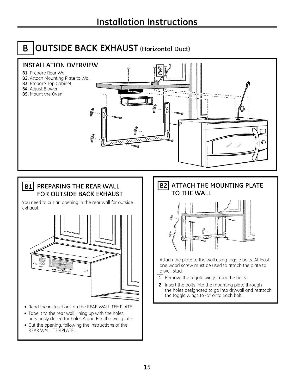
I-B-IOUTSIDE BACK EXHAUST (Horizontal Duct)
INSTALLATION OVERVIEW
B1. Prepare Rear Wall
B2.Attach Mounting Plate to Wall
B3. Prepare Top Cabinet
B4.Adjust Blower
B5. Mount the Oven
I
I
I
I
I
I
I
I-_ PREPARING THE REAR WALL
FOR OUTSIDE BACK EXHAUST
You need to cut an opening in the rear wall for outside
exhaust.
• Read the instructions on the REARWALL TEMPLATE.
• Tape it to the rear wall, lining up with the holes
previously drilled for holes A and B in the wall plate.
• Cut the opening, following the instructions of the
REARWALL TEMPLATE.
r-_ ATTACH THE MOUNTING PLATE
TO THE WALL
Attach the plate to the wall using toggle bolts. At least
one wood screw must be used to attach the plate to
a wall stud.
[_ Remove the toggle wings from the bolts.
[_ Insert the bolts into the mounting plate through
the holes designated to go into drywall and reattach
the toggle wings to 3A"onto each bolt.
15
Installation Instructions
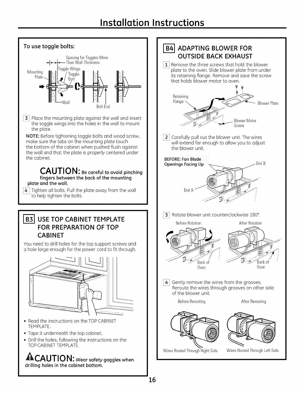
To use toggle bolts:
Spacingfor TogglesMore
_l_,--_-,_ ThanWall Thickness
Mounting ToggleWings
Platenl_ !
Wall BoltEnd
[_ Place the mounting plate against the wall and insert
the toggle wings into the holes in the wall to mount
the plate.
NOTE: Before tightening toggle bolts and wood screw,
make sure the tabs on the mounting plate touch
the bottom of the cabinet when pushed flush against
the wall and that the plate is properly centered under
the cabinet.
CAUTIO N: Becarefultoavoidpinching
fingers between the back of the mounting
plate and the wall.
[_ Tighten all bolts. Pull the plate away from the wall
to help tighten the bolts.
1-_ USE TOP CABINET TEMPLATE
FOR PREPARATION OF TOP
CABINET
You need to drill holes for the top support screws and
a hole large enough for the power cord to fit through.
• Read the instructions on the TOP CABINET
TEMPLATE.
• Tape it underneath the top cabinet.
• Drill the holes, following the instructions on the
TOP CABINET TEMPLATE.
A,..^, ,-,-,,-,
JUL_,,,/_IJ/I _.,/I_1: Wear safety goggles when
drilling holes in the cabinet bottom.
1-_ ADAPTING BLOWER FOR
OUTSIDE BACK EXHAUST
[_ Remove the three screws that hold the blower
plate to the oven. Slide blower plate from under
its retaining flange. Remove and save the screw
that holds blower motor to oven.
t_
Retaining _i!_'_<_
F, n0e\ ,ower
__>-_-_. _e/_ Blower Motor
.._ _:._ _.4 Screw
[_ Carefully pull out the blower unit. The wires
will extend far enough to allow you to adjust
the blower unit.
BEFORE: Fan Blade
Openings Facing
End
[_ Rotate blower unit counterclockwise 180°.
BeforeRotation AfterRotation
Backof
Oven Oven
3ackof
[_ Gently remove the wires from the grooves.
Reroute the wires through grooves on other side
of the blower unit.
BeforeRerouting After Rerouting
Wires RoutedThroughRightSide Wires RoutedThroughLeft Side
16
Installation Instructions
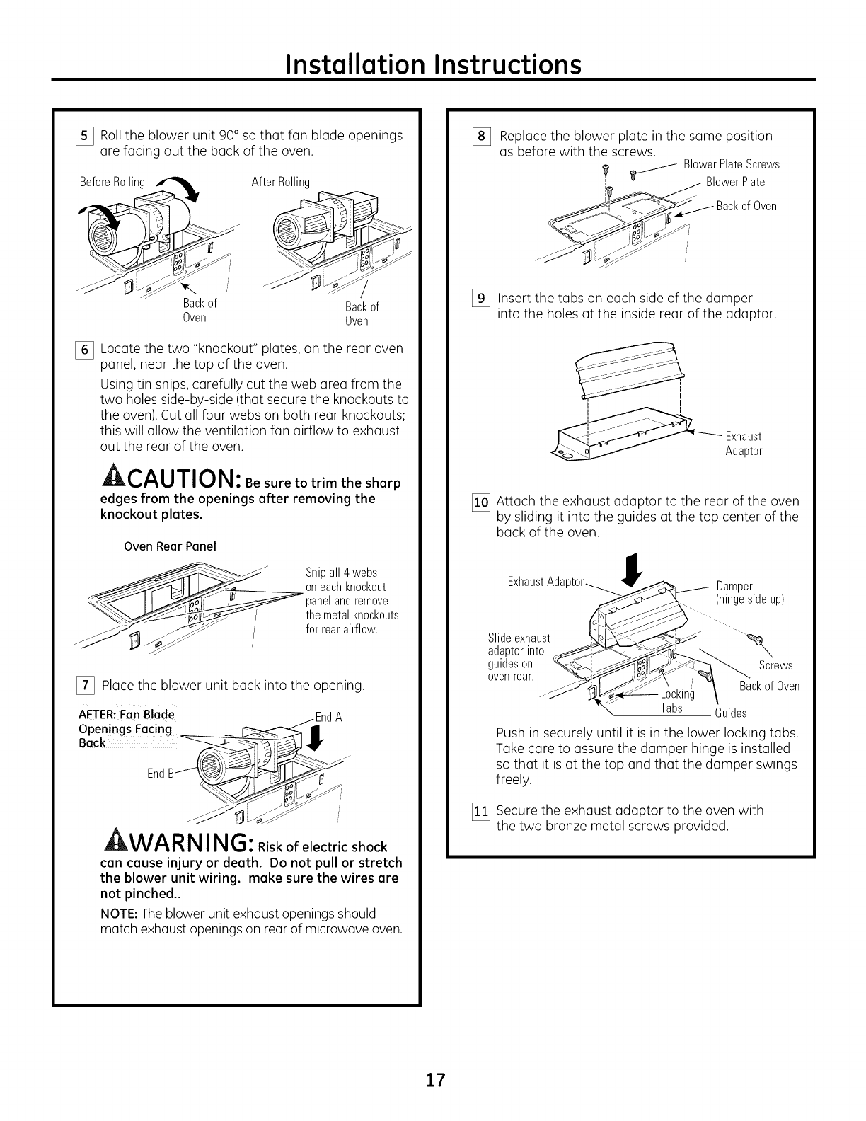
[_ Rollthe blower unit 90° so that fan blade openings
are facing out the back of the oven.
BeforeRollin_
Backof
Oven
After Rolling
Backof
Oven
[_ Locate the two "knockout" plates, on the rear oven
panel, near the top of the oven.
Using tin snips, carefully cut the web area from the
two holes side-by-side (that secure the knockouts to
the oven). Cut all four webs on both rear knockouts;
this will allow the ventilation fan airflow to exhaust
out the rear of the oven.
A,--^, ,-r,,-,t,,
Jll!_,l'_U/I _1_1 : Be sure to trim the sharp
edges from the openings after removing the
knockout plates.
Oven Rear Panel
__ Snipall4webs
oneachknockout
__ panelandremove
_.____ /themetalknockouts
_ __z /forrearairflow.
[_ Place the blower unit buck into the opening.
AFTER:FanBlade -EndA
Openings Facing
i i f
EndB@_
WA RNING:Riskofelectricshock
can cause injury or death. Do not pull or stretch
the blower unit wiring, make sure the wires are
not pinched..
NOTE:The blower unit exhaust openings should
match exhaust openings on rear of microwave oven.
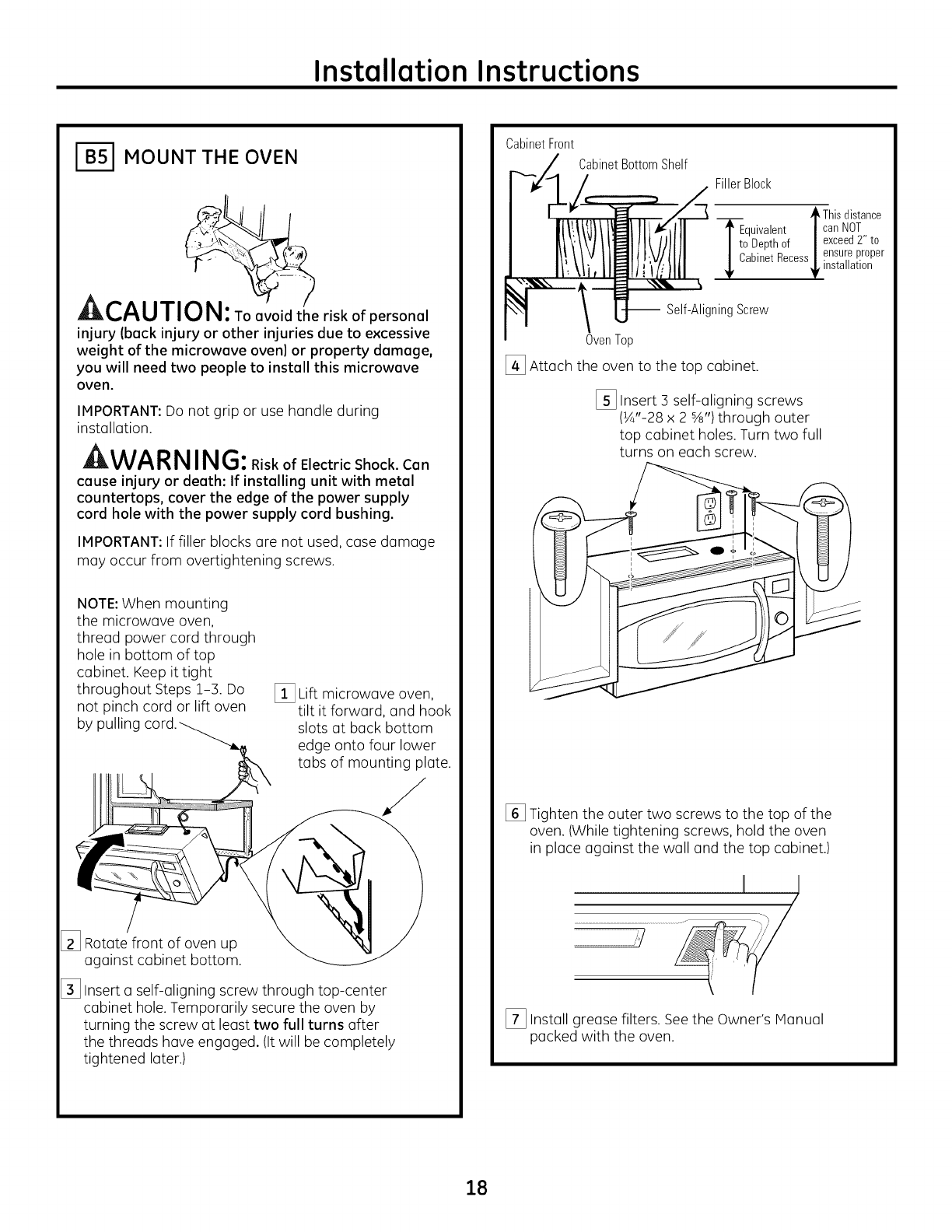
%Replace the blower plate in the same position
asbefore with the screws.
_ Blower Plate Screws
Blower Plate
_i <[_>_'_ Backof Oven
J ...... l
[_ Insert the tabs on each side of the dumper
into the holes at the inside rear of the adaptor.
_ Exhaust
Adaptor
[_ Attach the exhaust adaptor to the rear of the oven
by sliding it into the guides at the top center of the
back of the oven.
Exhaust Ada per
(hingesideup)
Slideexhaust _x,
adaptorinto
guideson Screws
oven rear. Backof Oven
Locking
Tabs Guides
Push in securely until it is in the lower locking tubs.
Take care to assure the dumper hinge is installed
so that it is at the top and that the dumper swings
freely.
[] Secure the exhaust adaptor to the oven with
the two bronze metal screws provided.
17
Installation Instructions
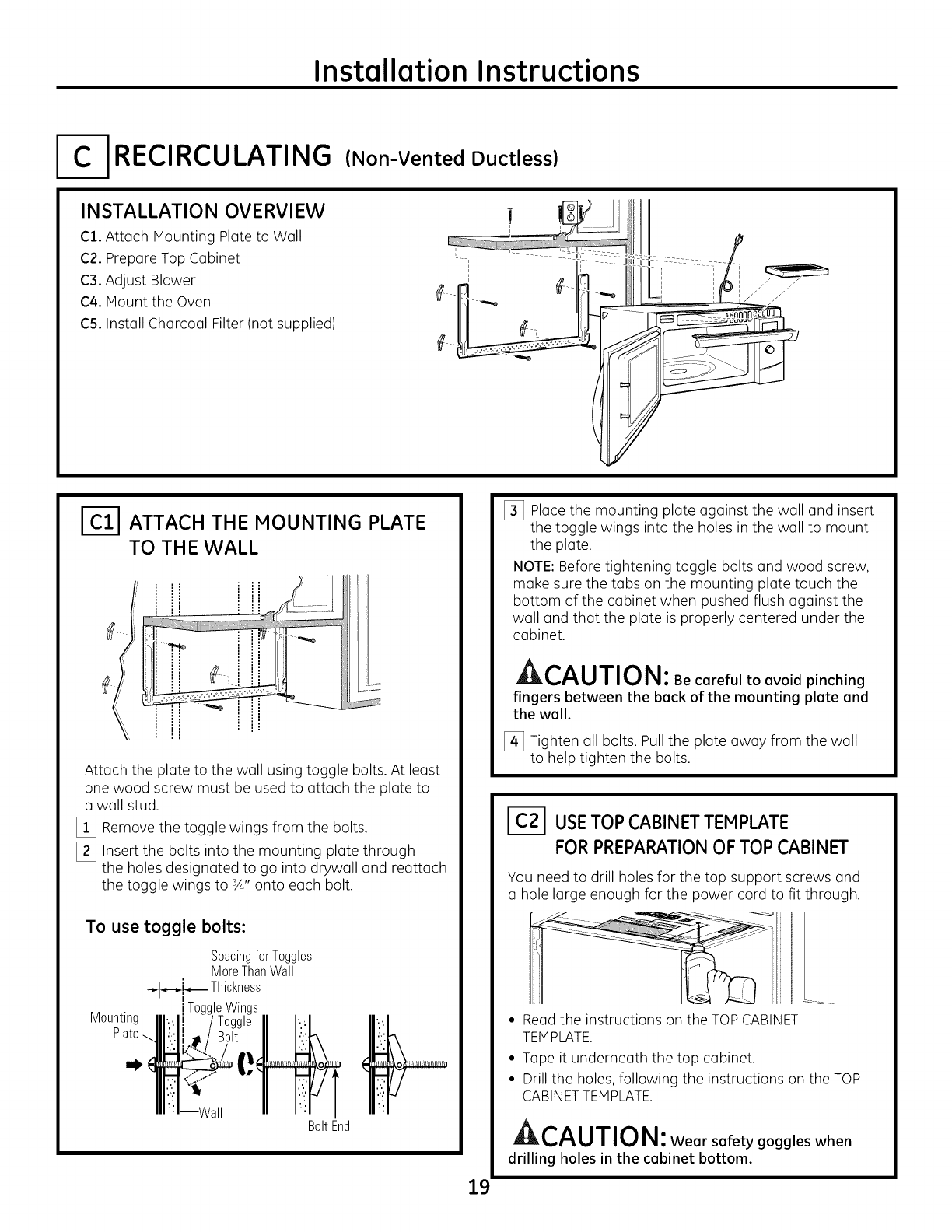
1-_ MOUNT THE OVEN
: kCAUTI risk of personal
inJury (back inJury or other inJuries due to excessive
weight of the microwave oven| or property damage,
you will need two people to install this microwave
oven.
IMPORTANT: Do not grip or use handle during
installation.
WA RNING:RiskofElectricShock.Can
cause inJury or death: If installing unit with metal
countertops, cover the edge of the power supply
cord hole with the power supply cord bushing.
IMPORTANT: If filler blocks are not used, case damage
may occur from overtightening screws.
NOTE: When mounting
the microwave oven,
thread power cord through
hole in bottom of top
cabinet. Keep it tight
throughout Steps 1-3. Do
not pinch cord or lift oven
by pulling
[_ Lift microwave oven,
tilt it forward, and hook
slots at back bottom
edge onto four lower
tabs of mounting plate.
[_ Rotate front of oven up
against cabinet bottom.
[_ Insert a self-aligning screw through top-center
cabinet hole. Temporarily secure the oven by
turning the screw at least two full turns after
the threads have engaged. (It will be completely
tightened later.)
CabinetFront
CabinetBottomShelf
Filler Block
/ikThisdistance
TEquivalent |can NOT
I to Depthof | exceed2" to
/ ensureproper
_ CabinetRecess
_ installation
-- Self-AligningScrew
OvenTop
[_ Attach the oven to the top cabinet.
[_ Insert 3 self-aligning screws
(¼"-28 x 2 %") through outer
top cabinet holes. Turn two full
turns on each screw.
[] Tighten the outer two screws to the top of the
oven. (While tightening screws, hold the oven
in place against the wall and the top cabinet.)
IIj )
[_ Install grease filters. Seethe Owner's Manual
packedwiththeoven.
18
Installation Instructions
[ RECIRCULATING (Non-Vented Ductless)
INSTALLATION OVERVIEW
C1. Attach Mounting Plate to Wall
C2. Prepare Top Cabinet
C3. Adjust Blower
C4. Mount the Oven
C5. Install Charcoal Filter (not supplied)
ATTACH THE MOUNTING PLATE
TO TH E WALL
Attach the plate to the wall using toggle bolts. At least
one wood screw must be used to attach the plate to
a wall stud.
[_ Remove the toggle wings from the bolts.
[_ Insert the bolts into the mounting plate through
the holes designated to go into drywall and reattach
the toggle wings to ¾" onto each bolt.
To use toggle bolts:
Mounting
SpacingforToggles
MoreThanWall
-_..-_i_ Thickness
i
iToggleWings
JVall BoltEnd
[_ Place the mounting plate against the wall and insert
the toggle wings into the holes in the wall to mount
the plate.
NOTE: Before tightening toggle bolts and wood screw,
make sure the tabs on the mounting plate touch the
bottom of the cabinet when pushed flush against the
wall and that the plate is properly centered under the
cabinet.
CAUTI O N: Becarefultoavoidpinching
fingers between the back of the mounting plate and
the wall.
[_ Tighten all bolts. Pull the plate away from the wall
to help tighten the bolts.
I-_-1 USETOPCABINETTEMPLATE
FORPREPARATIONOF TOP CABINET
You need to drill holes for the top support screws and
a hole large enough for the power cord to fit through.
19
• Read the instructions on the TOP CABINET
TEMPLATE.
• Tape it underneath the top cabinet.
• Drill the holes, following the instructions on the TOP
CABINET TEMPLATE.
A,,-^| ,T,,-,_,
J::IL,/'_U/I U I_1 : Wear safety goggles when
drilling holes in the cabinet bottom.
Installation Instructions
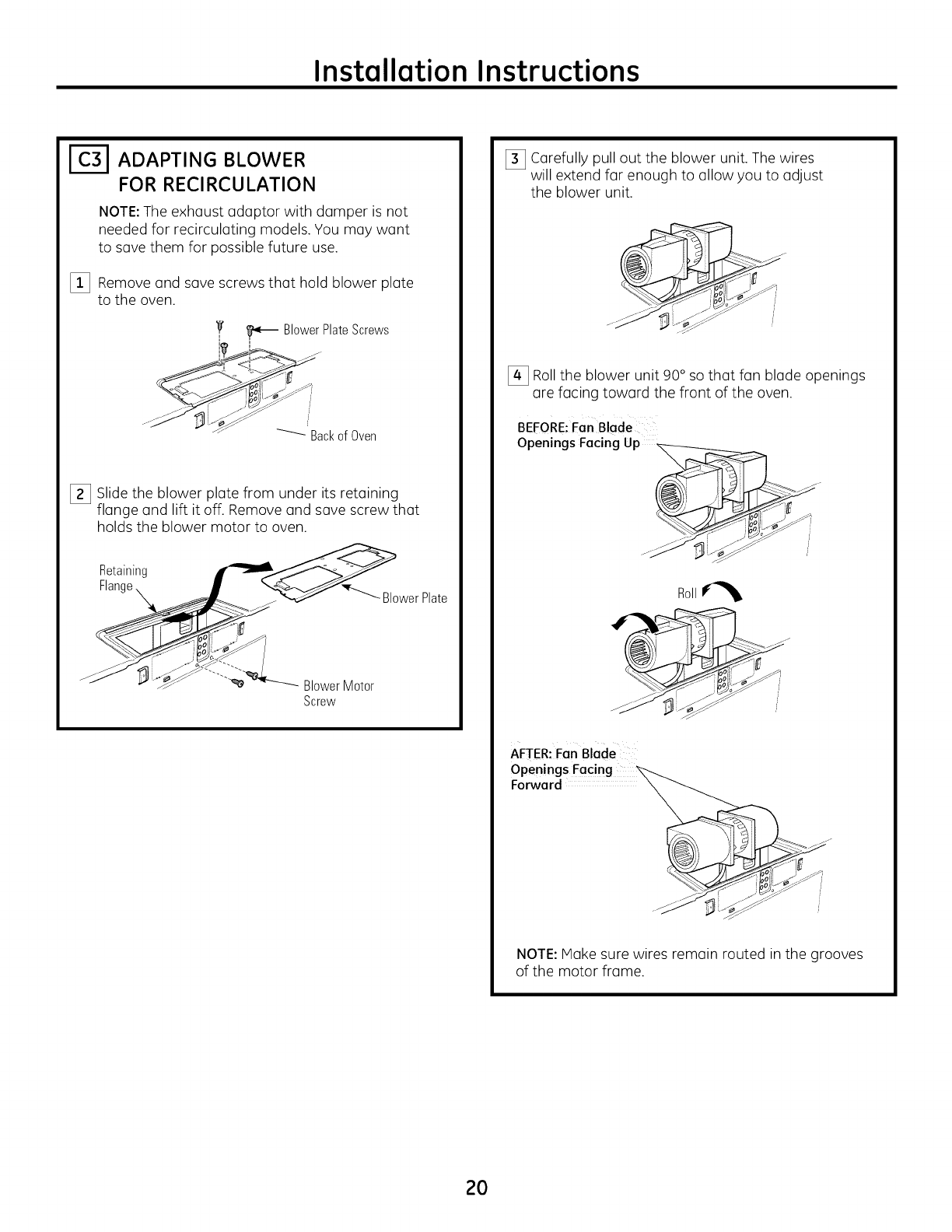
ADAPTING BLOWER
FOR RECIRCULATION
NOTE:The exhaust adaptor with damper is not
needed for recirculating models. You may want
to save them for possible future use.
[_3 Remove and save screws that hold blower plate
to the oven.
7 _ Blower Plate Screws
_-_ BackofOven
[_3 Slide the blower plate from under its retaining
flange and lift it off. Remove and save screw that
holds the blower motor to oven.
Retaining __
Flange _ J "_4__---..._ D,r
'_f _ BlowerPlate
- _ _'_...... BlowerMotor
Screw
[_3 Carefully pull out the blower unit. The wires
will extend far enough to allow you to adjust
the blower unit.
[_ Roll the blower unit 90° so that fan blade openings
are facing toward the front of the oven.
BEFORE:Fan Blade
Openings Facing Up
Roll_
J
AFTER: Fan Blade
Forward
NOTE: Hake sure wires remain routed in the grooves
of the motor frame.
2O
Installation Instructions
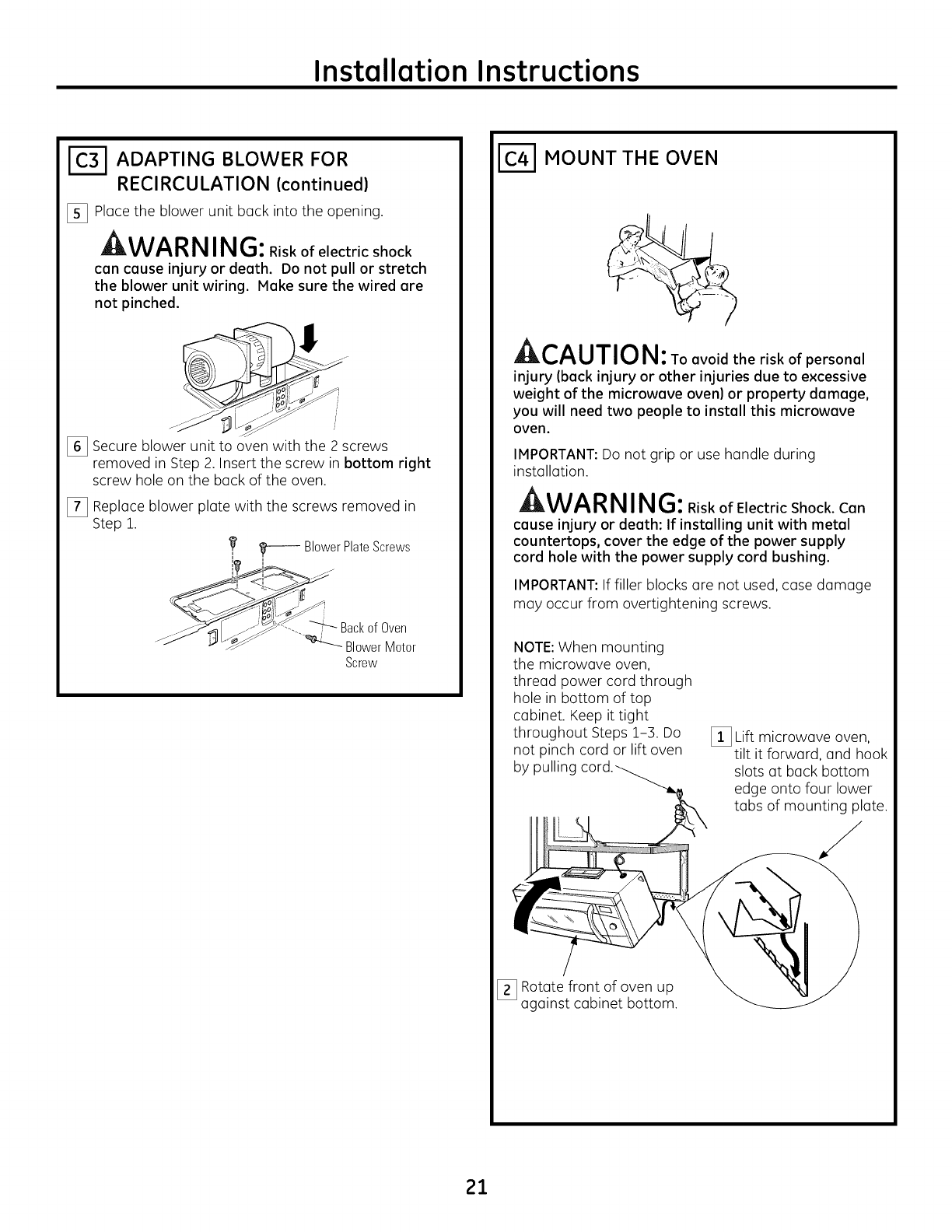
I-_ ADAPTING BLOWER FOR
RECIRCULATION (continued)
[_ Pl(]ce the blower unit b(]ck into the opening.
WA RN ING: Riskofelectricshock
con cause injury or death. Do not pull or stretch
the blower unit wiring. Make sure the wired are
not pinched.
i
[_ Secure blower unit to oven with the 2 screws
removed in Step 2. Insert the screw in bottom right
screw hole on the b(]ck of the oven.
[_ Repl(]ce blower pl(]te with the screws removed in
Step 1.
,_ _ BlowerPlateScrews
_! <! /
_t-.._ ._ Back of Oven
,4b_ Z _ BlowerMotor
Screw
I-_ MOUNT THE OVEN
AI_L,/'_U/I U I_1:TO avoid the risk of personel
injury (beck injury or other injuries due to excessive
weight of the microwave oven) or property damage,
you will need two people to install this microwave
oven.
IMPORTANT: Do not grip or use h(]ndle during
inst(]ll(]tion.
WA RN ING: RiskofElectricShock.Con
cause injury or death: If installing unit with metal
countertops, cover the edge of the power supply
cord hole with the power supply cord bushing.
IMPORTANT: If filler blocks (Ire not used, c(]se d(]m(]ge
m(]y occur from overtightening screws.
NOTE: When mounting
the microw(]ve oven,
thre(]d power cord through
hole in bottom of top
c(]binet. Keep it tight
throughout Steps 1-3. Do
not pinch cord or lift oven
by pulling
[_ Lift microw(]ve oven,
tilt it forw(]rd, (]nd hook
slots (]t b(]ck bottom
edge onto four lower
t(]bs of mounting pl(]te.
[_ Rot(]te front of oven up
(]g(]inst c(]binet bottom.
21
Installation Instructions
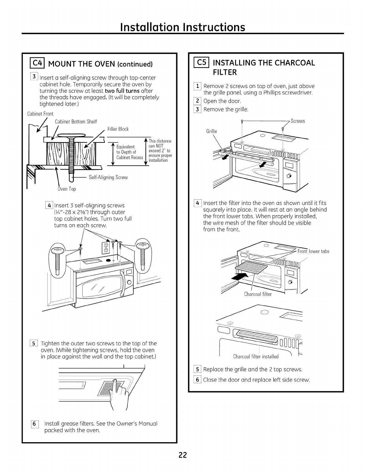
MOUNT THE OVEN (continued)
[_ Insert aself-aligning screw through top-center
cabinet hole. Temporarily secure the oven by
turning the screw at least two full turns after
the threads have engaged. (It will be completely
tightened later.)
CabinetFront
CabinetBottomShelf
FillerBlock
Thisdistance
TEquivalent | canNOT
I to Depthof I exceed2" to
/ ensureproper
_ CabinetRecess
_ installation
Oven Top
-- Self-Aligning Screw
[_ Insert 3 self-aligning screws
(¼"-28 x 2%") through outer
top cabinet holes. Turn two full
turns on each screw.
[] Tighten the outer two screws to the top of the
oven. (While tightening screws, hold the oven
in place against the wall and the top cabinet.)
[_ Install grease filters. See the Owner's Hanual
packed withthe oven.
1(;51 INSTALLING THE CHARCOAL
FILTER
[_ Remove 2 screws on top of oven,just above
the grille panel, using a Phillips screwdriver.
[_ Open the door.
[_ Remove the grille.
Grille !Screws
[_ Insert the filter into the oven as shown until it fits
squarely into place. It will rest at an angle behind
the front lower tabs. When properly installed,
the wire mesh of the filter should be visible
from the front.
Charcoalfilter
[_ Replace the grille and the 2 top screws.
[_ Close the door and replace left side screw.
22
Installation Instructions
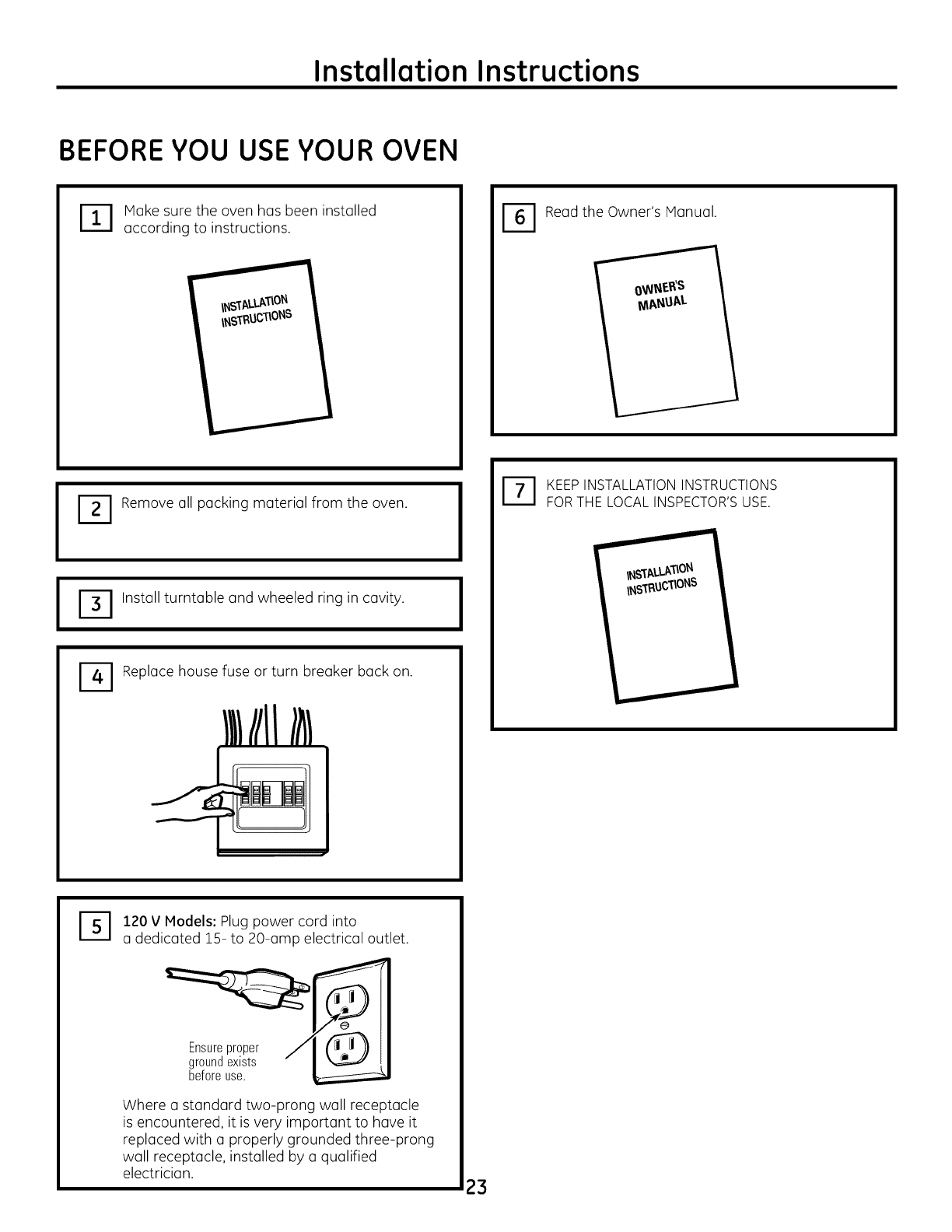
BEFOREYOU USEYOUR OVEN
'_ ake sure the oven has been installed
according to instructions. -I Read the Owner's Manual.
I
-I Remove all packing material from the oven.
D Install turntable and wheeled ring in cavity.
Replace house fuse or turn breaker back on.
IIIIIIll
I
DKEEP INSTALLATION INSTRUCTIONS
FOR THE LOCAL INSPECTOR'S USE.
%120 V Models: Plug power cord into
a dedicated 15- to 20-amp electrical outlet.
Ensureproper
groundexists
beforeuse.
Where u standard two-prong wall receptacle
is encountered, it is very important to have it
replaced with a properly grounded three-prong
wall receptacle, installed by a qualified
electrician. 23

49-40654
MFL59060904
(06-11 GE)
24
Printed in Korea
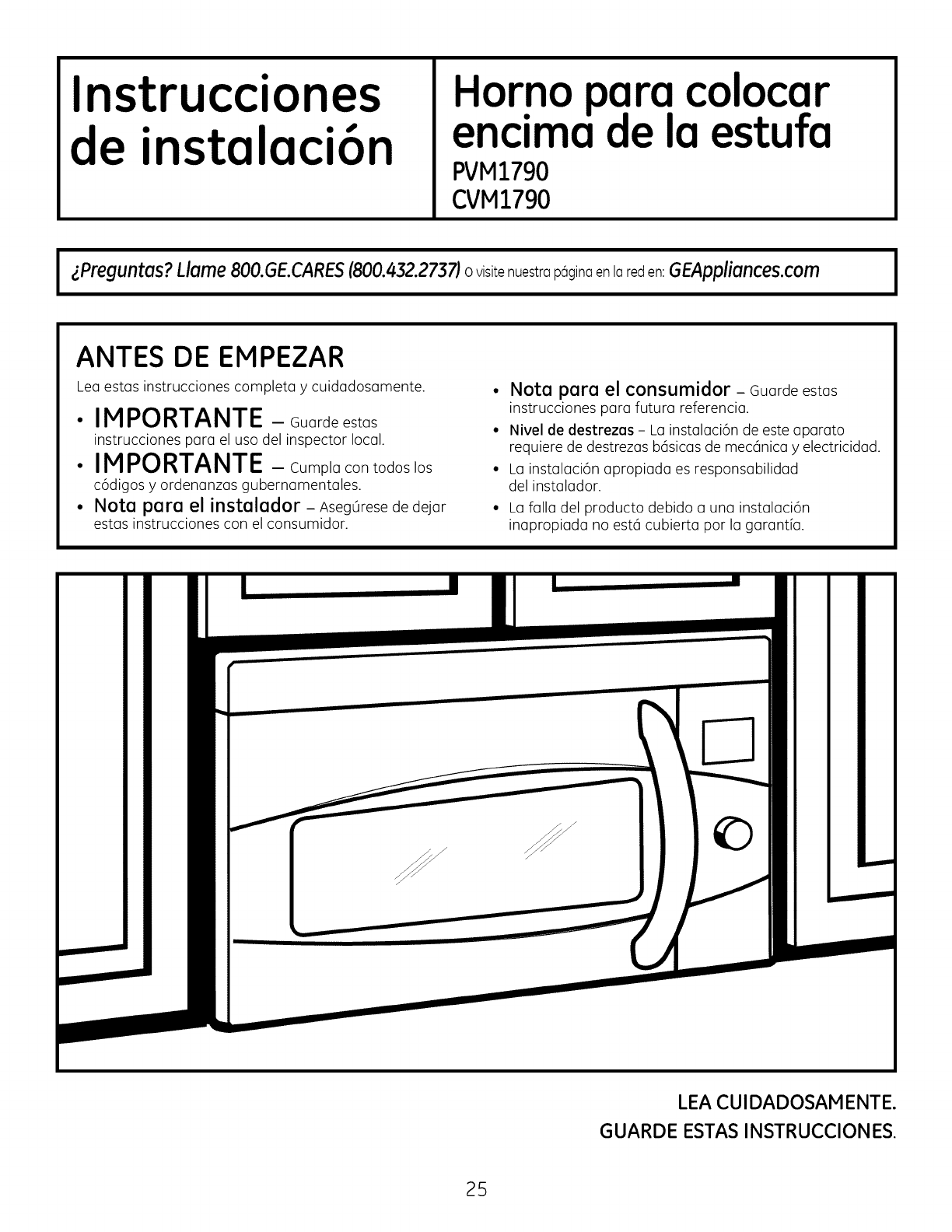
Instrucciones
de instalaci6n Horno para colocar
enclma de la estufa
PVM1790
CVM1790
I zPreguntas?dame 800.GE.CARES(800.432.2737)o visitenuestrop6ginoenIoreden: GEAppliances.com I
ANTES DE EMPEZAR
Lea estas instrucciones completa y cuidadosamente.
IMPORTANTE - Guardeestas
instrucciones para el usa del inspector local.
IMPORTANTE -Cumpla con todoslos
c6digosy ordenanzasgubernamentales.
Nota para el instalador - AsegOresede dejar
estas instrucciones con el consumidor.
•Nota para el consumidor - Guarde estas
instrucciones para futura referencia.
• Nivel de destrezas - La instalaci6n de este aparato
requiere de destrezas b6sicas de mec6nica y electricidad.
• La instalaci6n apropiada es responsabilidad
del instalador.
La falla del producto debido a una instalaci6n
inapropiada no est6 cubierta por la garantia.
LEACUlDADOSAM ENTE.
GUARDE ESTASINSTRUCCIONES.
25
Instrucciones de instalaci6n
CONTENIDO
Informaci6n general
Instrucciones de seguridad importantes ................... 27
Requisitos el@ctricos ...................................................... 27
Campana de escape ............................................... 28, 29
Da_os -Envio IInstalaci6n .......................................... 30
Partes incluidas ..............................................................30
Herramientas que necesitar6 ......................................31
Espacio de montaje ........................................................31
Guia de instalaci6n paso par paso
C6mo colocar el plato de montaje ....................... 32-34
C6mo remover el plato de montuje .....................32
C6mo encontrar madera s61ida
en la pared .......................................................................32
C6mo determinar la Iocalizaci6n
de las placas de la pared ..........................................33
C6mo alinear la placa de la pared .......................34
Tipos de instalaci6n ................................................ 35-46
[_ Escape superior ....................................
exterior 36-38
C6mo adherir la placa de
montaje a la pared ............................................36
Preparaci6n del gabinete superior ............37
Ensamblaje e instalaci6n
del adaptador ......................................................37
C6mo montar el homo .............................37, 38
C6mo ajustar el adaptador de escape....38
C6mo conectar el conducto .........................38
[_i_ Escape posterior externo ..................................
39-42
C6mo preparar la pared posterior
para el escape posterior exterior ...............39
C6mo adherir el plato de
montaje a la pared .....................................39, 40
Preparaci6n del gabinete superior ............40
C6mo adaptar el calefactor para
el escape posterior exterior ....................40, 41
C6mo montar el homo ....................................42
[_ Recirculaci6n ..........................................................43-46
C6mo adherir la placa de
montaje a la pared ............................................43
Preparaci6n del gabinete superior .............43
C6mo adaptar el calefactor
para la recirculaci6n .................................44,45
C6mo montar el homo ............................45, 46
C6mo instalar el filtro de carbonilla ..........46
Antes de comenzar a usar su horno ......................... 47
26
Instrucciones de instalaci6n
NSTRUCCIONES DE SEGURIDAD IMPORTANTES
Este producto requiere un tomacorriente el6ctrico
de tres patas conectado a tierra. El instalador debe
Ilevar a cabo una inspecci6n de continuidad a tierra
en la caja el6ctrica antes de comenzar la instalaci6n
para asegurar que la caja tomacorriente est8 conectada
a tierra de manera apropiada. Si no Io est6, o si
el tomacorriente no cumple con los requisitos
el6ctricos indicados (bajo la secci6n REQUISITOS
ELt_CTRICOS),se deber6 recurrir a un t6cnico
calificado para corregir cualquier deficiencia.
PRECAUCION:
Para seguridad personal,
remueva el fusible de la casa
o abra el interruptor de circuito antes
de comenzar la instalaci6n
para evitar descargas el6ctricas
severas o fatales
ADVERTENCIA: Riesgo de Descarga
El_ctrica. Puede ocasionar lesiones o la muerte: ESTE
ELECTRODOMI_STICO SE DEBE CONECTAR A TIERRA DE
FORMA CORRECTA afin de evitar descargas severas o
mortales.
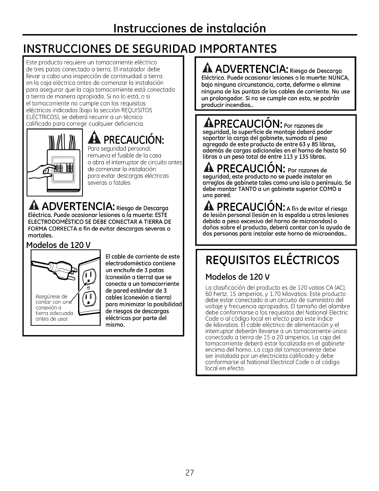
Modelos de 120 V
a
cont_rconun_
antes de usan
El cable de corriente de este
electrodom_stico contiene
un enchufe de 3 patas
(cone×i6n atierra) que se
conecta a un tomacorriente
de pared est6ndar de 3
cables (cone×i6n atierre)
para minimizar la posibilidad
de riesgos de descargas
el_ctricas par parte del
mismo.
ADVERTENCIA: Riesgo de Descarga
El_ctrica. Puede ocasionar lesiones o la muerte: NUNCA,
bajo ninguna circunstancia, carte, deforme o elimine
ninguna de los puntas de los cables de corriente. No use
un prolongador. Si no se cumple con esto, se podr6n
producir incendios..
_nnl--r,^H r,i _k i
_I"I_I-L,/'_U L,I Ul_l: Par razones de
seguridad, la superficie de montaje deber6 poder
soportar la carga del gabinete, sumado al peso
agregado de este producto de entre 63 y 85 libras,
adem6s de cargas adicionales en el horno de hasta 50
libras o un peso total de entre 113 y 135 libras.
A PRECAUCION: Porrazonesde
seguridad, este producto no se puede instalar en
arreglos de gabinete tales coma una isla o peninsula. Se
debe montar TANTO a un gabinete superior COMa a
una pared.
A
A PRECAUCION:A fin de evitar el riesgo
de lesi6n personal (lesi6n en la espalda u otras lesiones
debido a peso excesivo del horno de microondas) o
dafios sabre el producto, deber6 contar con la ayuda de
dos personas para instalar este horno de microondas..
REQUISITOS ELI CTRICOS
Modelos de 120 V
La clasificaci6n del producto es de Z20 vatios CA (AC),
60 hertz, 15 amperios, y 1.70 kilovatios. Este producto
debe estar conectado a un circuito de suministro del
voltaje y frecuencia apropiados. EltamaBo del alambre
debe conformarse a los requisitos del National Electric
Code o al c6digo local en efecto para este indice
de kilovatios. Elcable el6ctrico de alimentaci6n y el
interruptor deber6n Ilevarse a un tomacorriente Onico
conectado a tierra de 15 a 20 amperios. La caja del
tomacorriente deber6 estar Iocalizada en el gabinete
encima del horno. La caja del tomacorriente debe
ser instalada por un electricista calificado y debe
conformarse al National Electrical Code o al c6digo
local en efecto.
27
Instrucciones de instalaci6n
CAMPANA DE ESCAPE
NOTA:Lee lossiguientes dos p6gines solemente si plenea ventiler el escape hecie el exterior.
Si por el controrio planea recirculor el aire de vuelta hacia el sol6n, continSe en la p6gina 30.
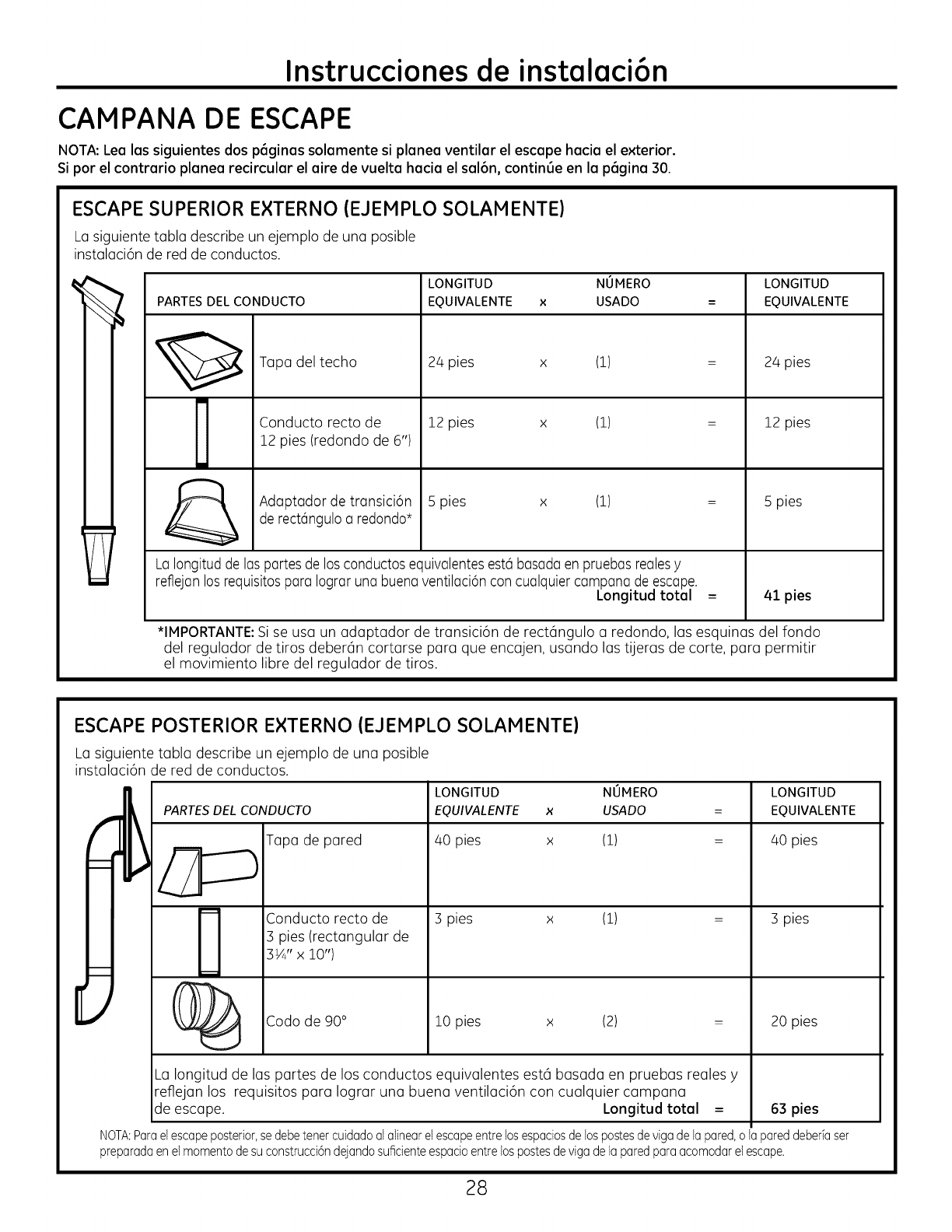
ESCAPE SUPERIOR E×TERNO (EJEMPLO SOLAMENTE)
La siguiente tabla describe un ejemplo de una posible
instalaci6n de red de conductos.
PARTES DEL CONDUCTO
Tapa del techo
Conducto recto de
12 pies (redondo de 6")
LONGITUD NOMERO
EQUIVALENTE x USADO
24 pies x (1)
12 pies x (1)
Adaptador de transici6n 5 pies x (1)
de rect6nguloa redondo*
LaIongitudde las partes de los conductosequivalentesesta basadaen pruebas realesy
reflejan los requisitospara Iograr una buenaventilaci6n con cualquier campanade escape.
Longitud totol
LONGITUD
EQUIVALENTE
2/4pies
12 pies
5 pies
41 pies
*IMPORTANTE:Sise usa un adaptador de transici6n de rect6ngulo a redondo, las esquinas del fondo
del regulador de tiros deber6n cortarse para que encajen, usando las tijeras de corte, para permitir
el movimiento libre del regulador de tiros.
ESCAPE POSTERIOR E×TERNO (EJEMPLO SOLAMENTE)
La siguiente tabla describe un ejemplo de una posible
instalaci6n de red de conductos.
LONGITUD
PARTES DEL CONDUCTO
Tapa de pared
Conducto recto de
3 pies (rectangular de
3¼" x i0")
EQUIVALENTE
40 pies
3 pies
x
x
NOMERO
USADO
(1)
(1)
LONGITUD
EQUIVALENTE
40 pies
3 pies
i
(_ Codo de 90° 10 pies x (2) = 20 pies
La Iongitud de las partes de los conductos equivalentes est6 basada en pruebas reales y
reflejan los requisitos para Iograr una buena ventilaci6n con cualquier campana
de escape. Longitud total = 63 pies
NOTA:Para el escape posterior, se debe tenet cuidado al alinear el escape entre Fosespacios de Fospostes de vigade Fapared, o la pared deberia ser
preparadaenelmomentodesuconstrucci6ndejandosuficienteespacioentreFospostesderigadeFaparedparaacomodarelescape.
28
Instrucciones de instalaci6n
NOTA: Si usted necesita instalar conductos, tenga pendiente
que la Iongitud total del conducto rectangular de 3½" x 10"
o el conducto redondo de 6" de di6metro no debe
sobrepasar 140 pies equivalentes.
La ventilaci6n externa requiere un CONDUCTO DE CAMPANA
DE ESCAPE. Lea Io siguiente cuidadosamente.
NOTA: Es importante que la ventilaci6n sea instalada usando
la ruta m6s directa y con la menor cantidad de codos posible.
Esto asegura la ventilaci6n del escape y ayuda a prevenir
bloqueos. Tambi6n, cerci6rese de que el regulador de tiro
pende libremente y nada bloquea los conductos.
Conexiones de escape:
La campana de escape ha sido dise_ada para encajar con
un conducto rectangular de 3¼" x 10" est6ndar.
Siun conducto redondo es necesario, se debe usar
un adaptador de transici6n de rectangular a redondo.
No use un conducto menor de 6" de di6metro.
Longitud m6xima del conducto:
Para Iograr un movimiento satisfactorio del aire, la
Iongitud total del conducto rectangular de 3¼" x 10"
o el conducto redondo de 6" de di6metro no debe
sobrepasar 140 pies equivalentes.
Los codos, transiciones, paredes y tapas
de techo, etc., presentan resistencia adicional al flujo
de aire y son equivalentes a una secci6n de conducto
recto el cual es m6s largo que su tamaBo fisico real.
Cuando calcule la Iongitud total del conducto, agregue
las longitudes equivalentes de todas las transiciones
y adaptadores, m6s la Iongitud de todas las secciones
de conducto rectas. La tabla m6s adelante muestra
c6mo puede calcular la Iongitud aproximada de la red
de conductos usando pies aproximados de longitudes
equivalentes de algunos conductos tipicos.
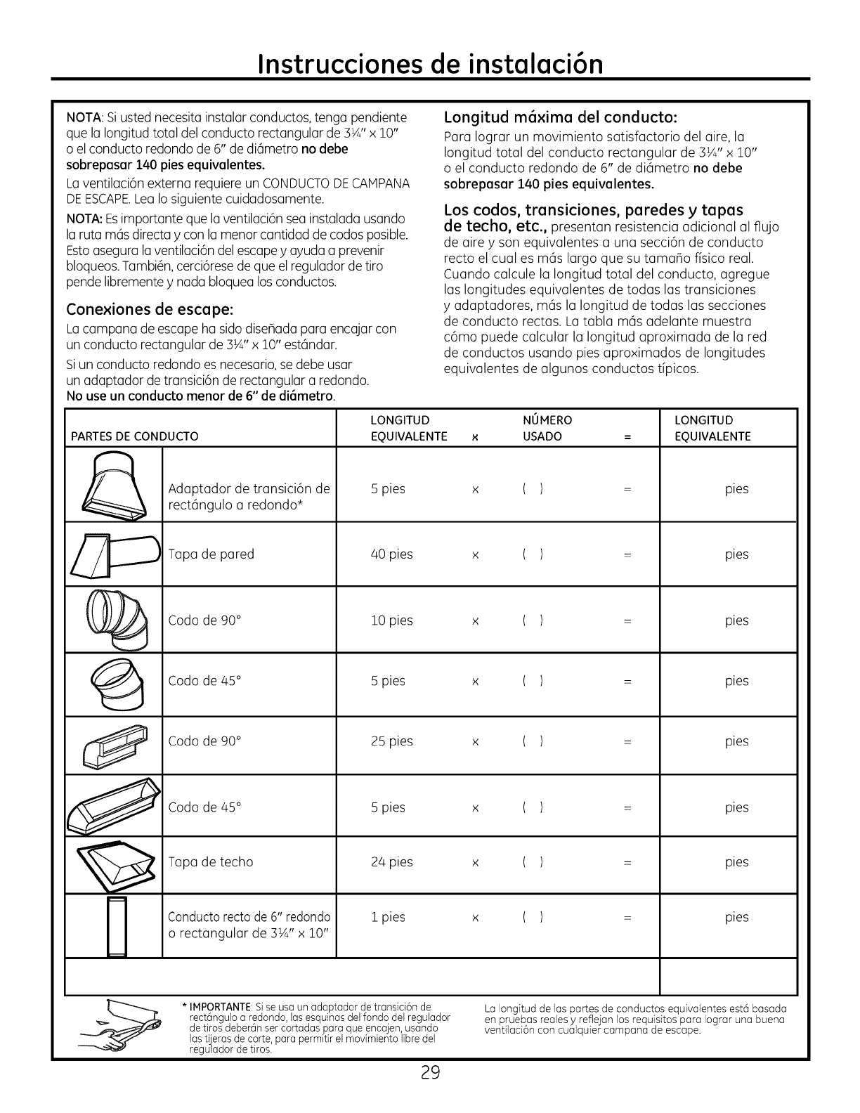
LONGITUD NUMERO LONGITUD
PARTES DE CONDUCTO EQUIVALENTE x USADO =EQUIVALENTE
Adaptador de transici6n de Spies x ( ) = pies
rect6ngulo a redondo*
Tapa de pared 40 pies x ( ) = pies
C}_ Codode90 ° lOpies x ( ) = pies
Codo de 45° 5 pies x ( ) = pies
Codo de 90° 25 pies x ( ) = pies
_ Codode45 ° 5 ( )
pies xpies
Tapa de techo 24 pies x ( ) = pies
m
Conducto rectode 6" redondo 1 pies x ( ) = pies
o rectangular de 3½" x 10"
* IMPORTANTE Sise usa un adaptador de transici6n de La Iongitud de las partes de conductos equivalentes est(_ basada
rect6ng@oa redondo, las esquinas del fondo del regulador en pruebas reales yreflejan los requisitos para Iograr una buena
de tiros deber6n ser cortadas para que encajen, usando venti4aci6n con cualquier campana de escape.
1astijeras de corte, para permitir el movimiento libre del
regulador de tiros.
29
Instrucciones de instalaci6n
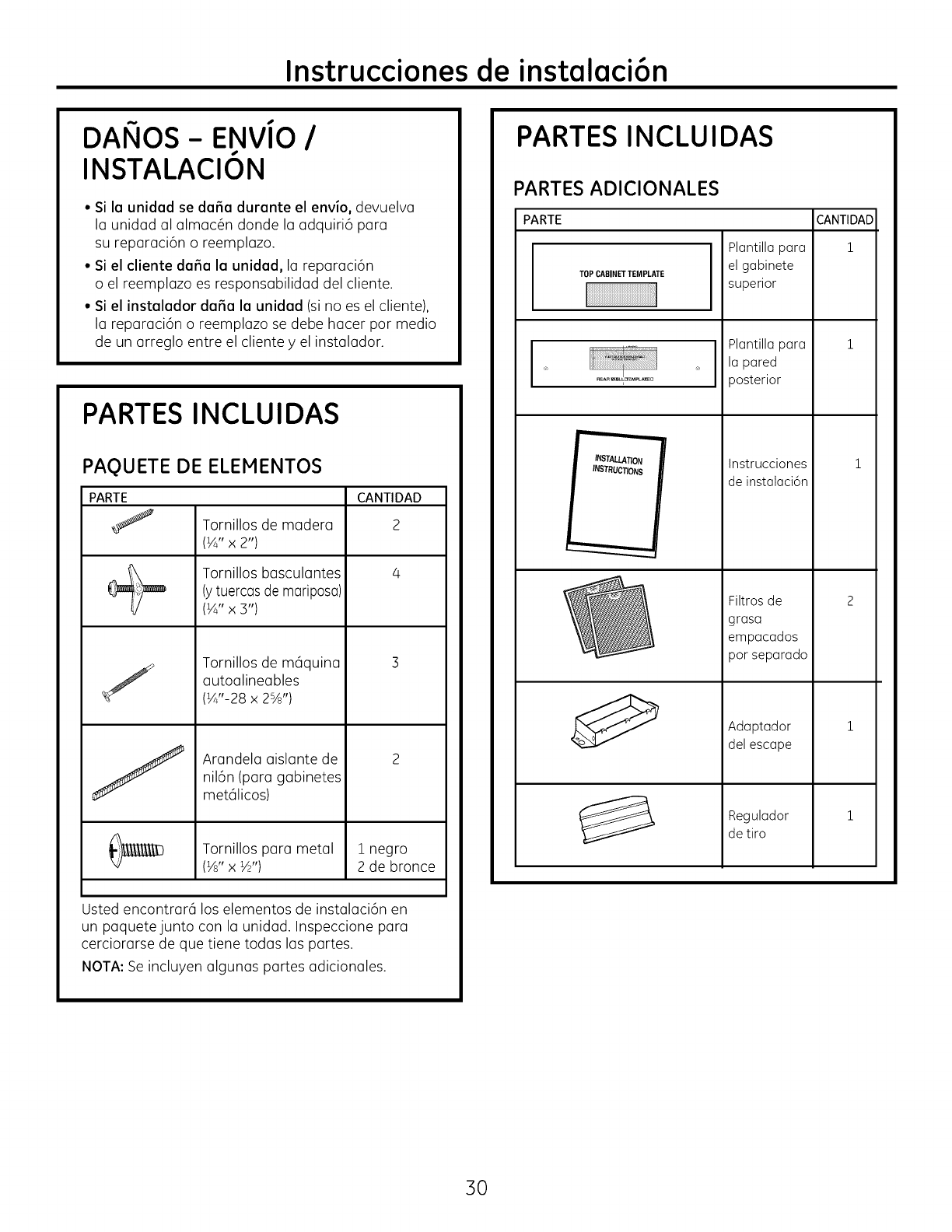
DAIqOS- ENViO I
INSTALACION
• Si la unidad se daSa durante el envio, devuelva
la unidad al almac6n donde la adquiri6 para
su reparaci6n o reemplazo.
• Si el cliente dafia la unidad, la reparaci6n
o el reemplazo es responsabilidad del cliente.
• Si el instalador dafia la unidad (si no es el cliente),
la reparaci6n o reemplazo se debe hacer por medio
de un arreglo entre el cliente yel instalador.
PARTES INCLUIDAS
PAQUETE DE ELEMENTOS
PARTE CANTIDAD
j Tornillos de madera 2
(¼" x 2")
Tornillos basculantes 4
(ytuercas de mariposa)
(¼" x 3")
Tornillos de mc_quina
autoalineables
(¼"-28 x 2%')
Arandela aislante de
nil6n (para gabinetes
met@cos)
Tornillos para metal 1 negro
(½" x W') 2 de bronce
Usted encontrarc_ los elementos de instalaci6n en
un paquetejunto con la unidad. Inspeccione para
cerciorarse de que tiene todas las partes.
NOTA: Se incluyen algunas partes adicionales.
PARTES INCLUIDAS
PARTES ADICIONALES
PARTE
TOPCABINETTEMPLATE
® I ®
REARWtL_EMPLA_U
INSTALLATION
INSTRUCTIONS
Plantilla para
el gabinete
superior
Plantilla para
la pared
posterior
Instrucciones
de instalaci6n
Filtros de
grasa
empacados
por separado
Adaptador
del escape
CANTIDAD
1
1
1
2
1
Regulador 1
de tiro
3O
Instrucciones de instalaci6n
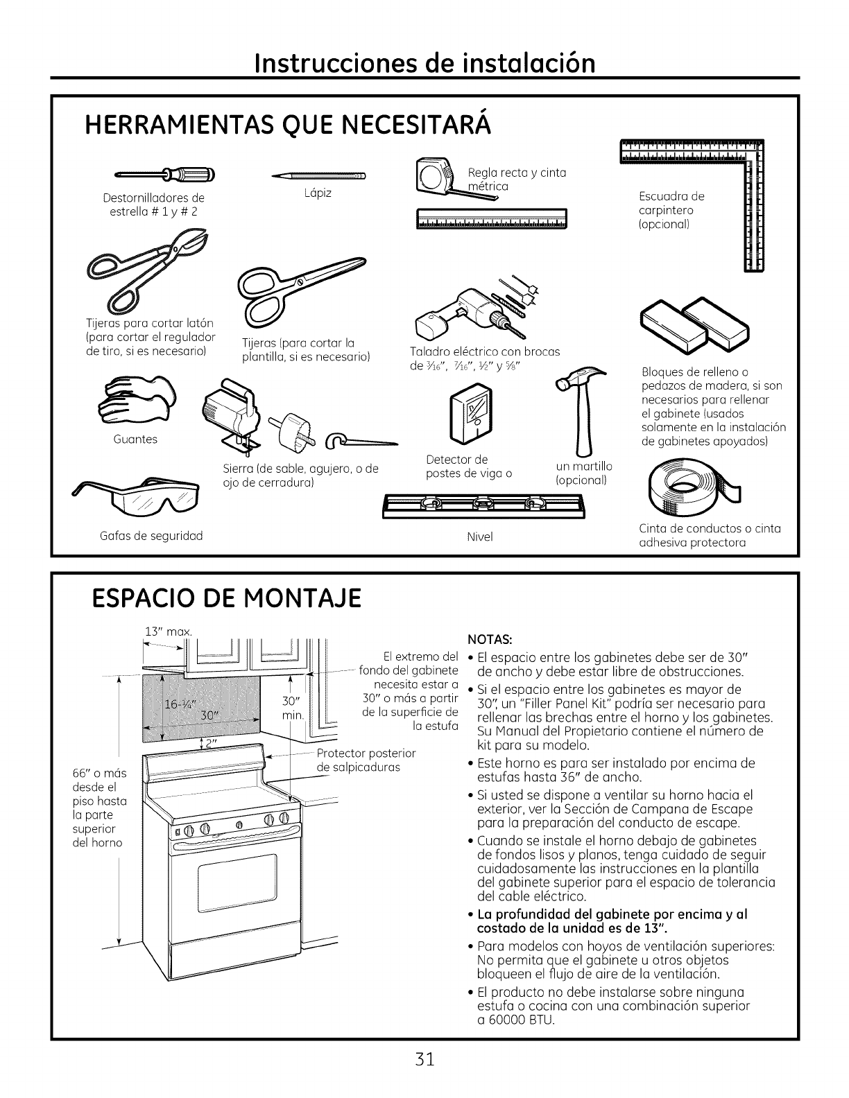
HERRAMIENTAS QUE NECESITARA
"=-' "_' I( "_\_I Regla recta y cinta
-" _ _ca
Destornilladores de Lapiz
estrella # 1 y # 2
Escuadra de
carpintero
(opcional)
Tijeras para cortar lat6n
(para cortar el regulador
de tiro, si es necesario) Tijeras(paracortar la
plantilla,si es necesario)
Sierra(desable,agujero,o de
ojode cerradura)
Gafas de seguridad
Taladroel@ctricocon brocas
de S/ld', _d', ½"y%"
Detector de un martillo
postesde viga o (opcional)
Nivel
Bloquesde rellenoo
pedazosde madera,si son
necesariospara rellenar
el gabinete (usados
solamenteen la instalaci6n
de gabinetesapoyados)
Cinta de conductos o cinta
adhesiva protectora
ESPACIO DE MONTAJE
El extremo del
del gabinete
necesita estar a
30" o mas a partir
de la superficie de
la estufa
66" o mas
desde el
piso hasta
la parte
superior
del homo
Protector posterior
de salpicaduras
NOTAS:
• Elespacio entre los gabinetes debe ser de 30"
de ancho y debe estar libre de obstrucciones.
• Siel espacio entre los gabinetes es mayor de
30",un "Filler Panel Kit" podria ser necesario para
rellenar las brechas entre el horno y los gabinetes.
Su Manual del Propietario contiene el nOmero de
kit para su modelo.
• Este horno es para ser instalado por encima de
estufas hasta 36" de ancho.
• Si usted se dispone a ventilar su horno hacia el
exterior, ver la Secci6n de Campana de Escape
para la preparaci6n del conducto de escape.
• Cuando se instale el horno debajo de gabinetes
de rondos lisos y pianos, tenga cuidado de seguir
cuidadosamente las instrucciones en la plantilla
del gabinete superior para el espacio de tolerancia
del cable el6ctrico.
• La profundidad del gabinete por encima y al
costado de la unidad es de 13".
• Para modelos con hoyos de ventilaci6n superiores:
No permita que el gabinete u otros objetos
bloqueen el flujo de aire de la ventilaci6n.
• El producto no debe instalarse sobre ninguna
estufa o cocina con una combinaci6n superior
a 60000 BTU.
31
Instrucciones de instalaci6n
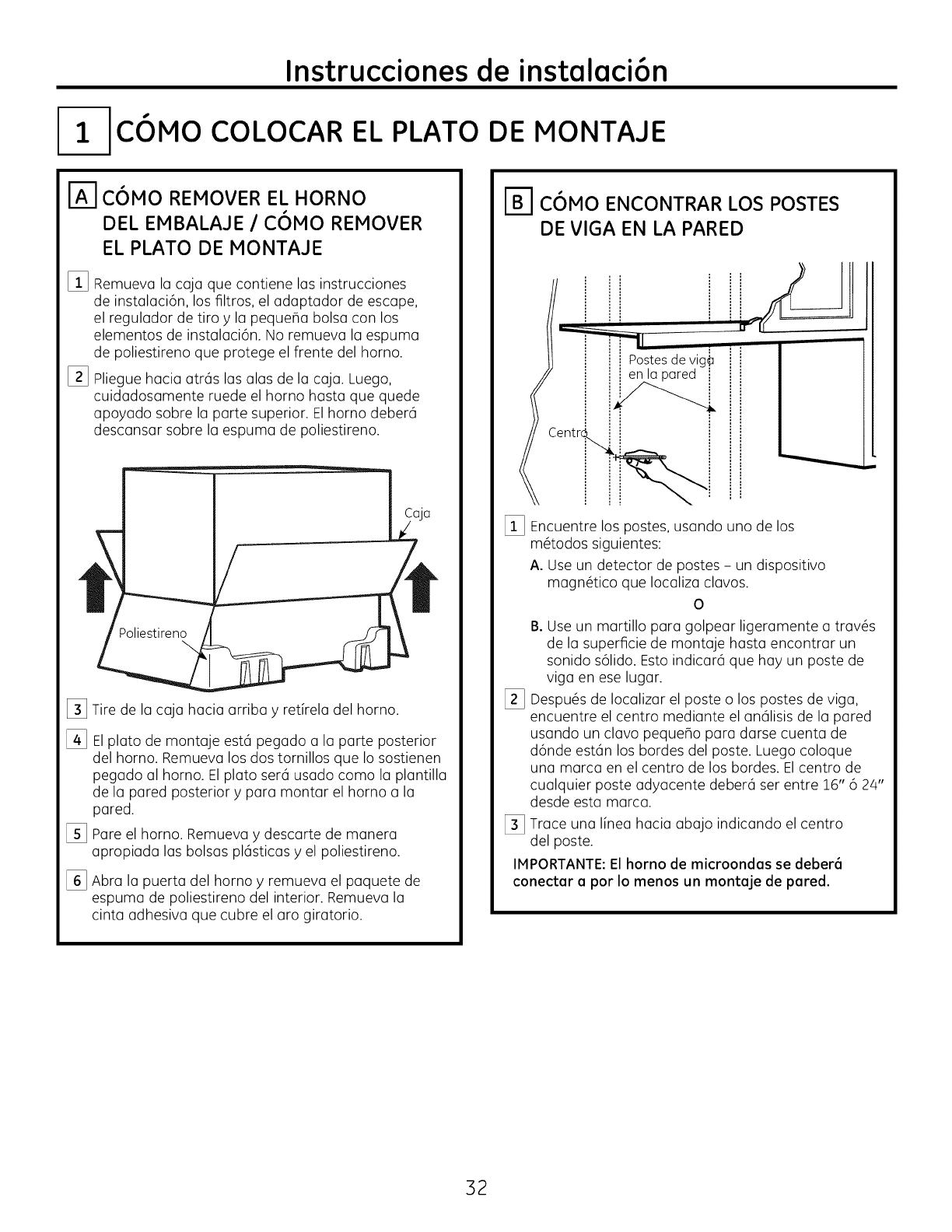
l- c6MO COLOCAR EL PLATO DE MONTAJE
r_ C6MO REMOVER EL HORNO
DEL EMBALAJE lC6MO REMOVER
EL PLATO DE MONTAJE
%
[]
Remueva la caja que contiene las instrucciones
de instalaci6n, los filtros, el adaptador de escape,
el regulador de tiro y la pequefia bolsa con los
elementos de instalaci6n. No remueva la espuma
de poliestireno que protege el frente del homo.
Pliegue hacia atr6s las alas de la caja. Luego,
cuidadosamente ruede el horno hasta que quede
apoyado sobre la parte superior. Elhomo deber6
descansar sobre la espuma de poliestireno.
Poliestireno
\
[_ Tire de la caja hacia arriba yretirela del homo.
[] El plato de montaje est6 pegado a la parte posterior
del horno. Remueva los dos tornillos que Io sostienen
pegado al homo. El plato ser6 usado como la plantilla
de la pared posterior ypara montar el homo a la
pared.
[_ Pare el homo. Remueva y descarte de manera
apropiada las bolsas pl6sticas y el poliestireno.
[_ Abra la puerta del horno y remueva el paquete de
espuma de poliestireno del interior. Remueva la
cinta adhesiva que cubre el aro giratorio.
C6MO ENCONTRAR LOS POSTES
DE VIGA EN LA PARED
'_ u,i
Postesdevig_
enla pared i
I
[_ Encuentre los postes, usando uno de los
m@odos siguientes:
A. Use un detector de postes - un dispositivo
magn@ico que Iocaliza clavos.
0
%
B. Use un martillo para golpear ligeramente a trav6s
de la superficie de montaje basra encontrar un
sonido s61ido.Esto indicar6 que hay un poste de
riga en ese lugar.
Despu6s de Iocalizar el poste o los postes de riga,
encuentre el centro mediante el an61isisde la pared
usando un clavo pequefio para darse cuenta de
d6nde est6n los bordes del poste. Luego coloque
una marca en el centro de los bordes. Elcentro de
cualquier poste adyacente deber6 ser entre 16" 6 24"
desde esta marca.
[_ Trace una I[nea hacia abajo indicando el centro
del poste.
IMPORTANTE:El horno de microondas se deber6
conectar a por Io menos un montaje de pared.
32
Instrucciones de instalaci6n
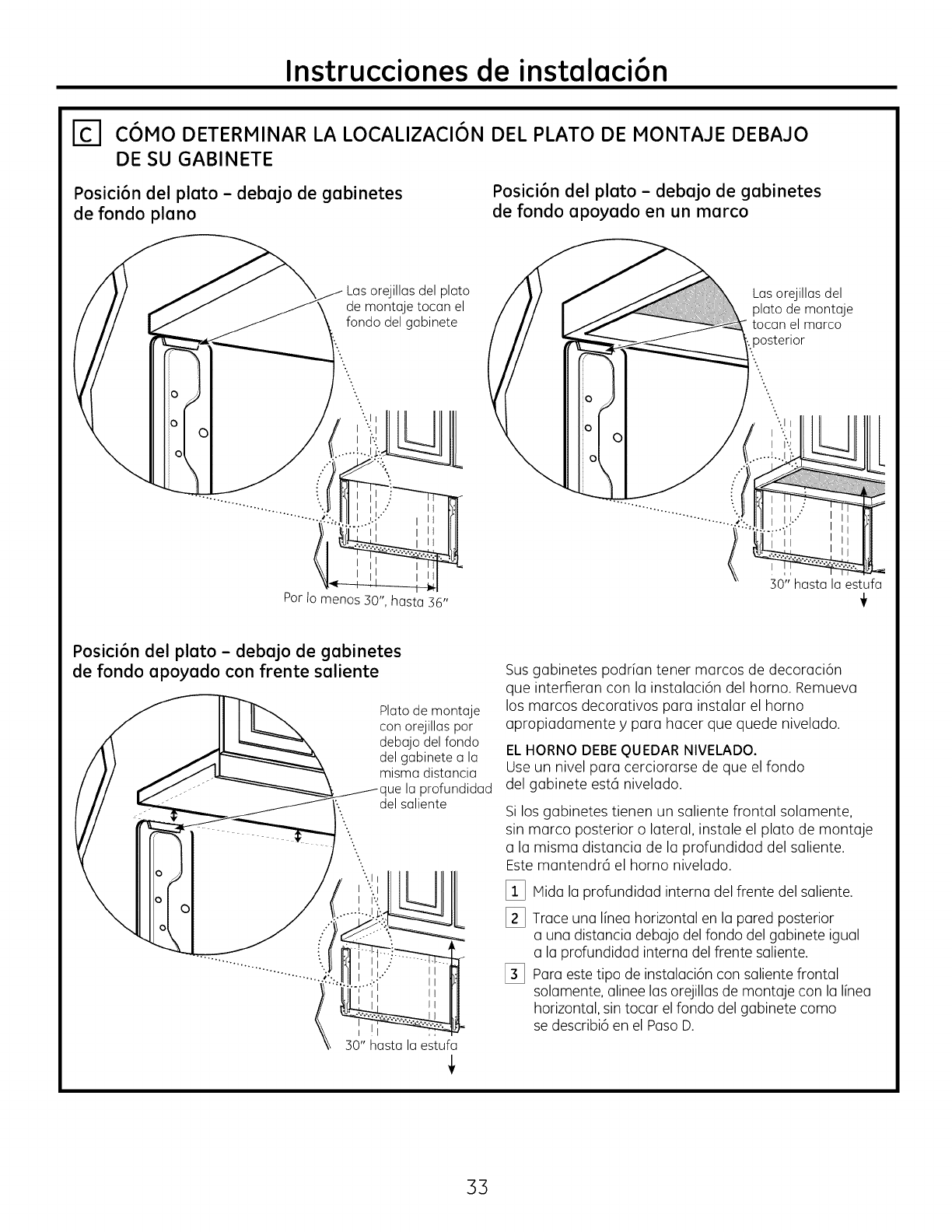
_-I C6MO DETERMINAR LA LOCALIZACI6N DEL PLATO DE MONTAJE DEBAJO
DE SU GABINETE
Posici6n del plato - debajo de gabinetes
de fondo piano
Posici6n del plato - debajo de gabinetes
de fondo apoyado en un marco
Las orejillas del plato
de montaje tocan el
fondo del gabinete
Las orejillas del
plato de montaje
tocan el marco
posterior
Por Io m enos 30", hasta 36"
30"" hasta la estufa
Posici6n del plato - debajo de gabinetes
de fondo apoyado con frente saliente
0
Plato de montaje
con orejillas por
debajo del fondo
del gabinete a la
misma distancia
profundidad
del saliente
30" hasta la estufa
Sus gabinetes podrian tener marcos de decoraci6n
que interfieran con la instalaci6n del horno. Remueva
los marcos decorativos para instalar el homo
apropiadamente y para hacer que quede nivelado.
ELHORNO DEBE QUEDAR NIVELADO.
Use un nivel para cerciorarse de que el rondo
del gabinete est6 nivelado.
Si los gabinetes tienen un saliente frontal solamente,
sin marco posterior o lateral, instale el plato de montaje
a la misma distancia de la profundidad del saliente.
Este mantendr6 el horno nivelado.
_i_ Mida la profundidad interna del frente del saliente.
[_ Trace una linea horizontal en la pared posterior
a una distancia debajo del fondo del gabinete igual
a la profundidad interna del frente saliente.
[_ Para este tipo de instalaci6n con saliente frontal
solamente, alinee las orejillas de montaje con la linea
horizontal, sin tocar el fondo del gabinete como
se describi6 en el Paso D.
33
Instrucciones de instalacian
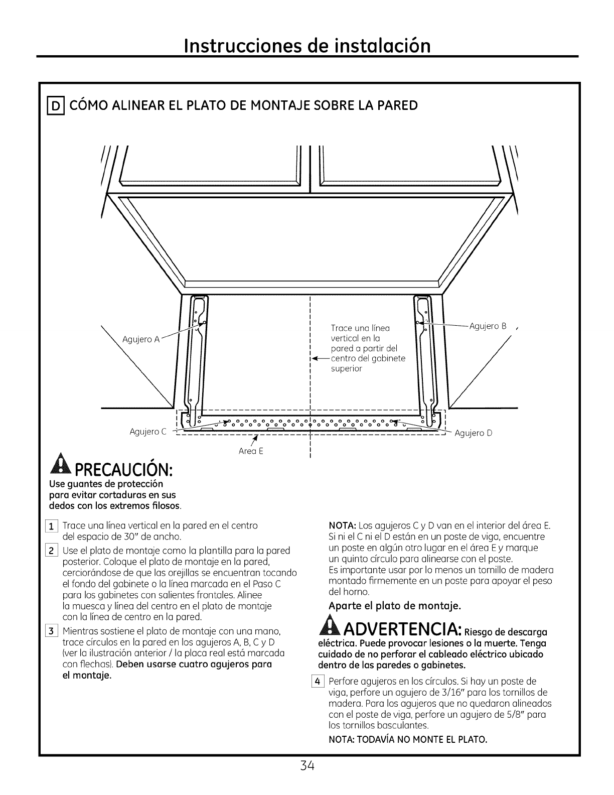
E CaMO ALINEAR EL PLATO DE MONTAJE SOBRE LA PARED
Agujero
I
I
AgujeroC
PRECAUCION:
Use guantes de proteccian
para evitar cortaduras en sus
dedos con los extremos filosos.
ET
J l Iuna f_ _Agujero B ,
Trace Ifnea
| II vertical en la II II /
|i pareda partirdel II II /
|,_centrodelgabinete II II /
! superior I/ /I __
L. ...................
I
/_ ........ T J Agujero D
Area E J
I
_i_ Trace una linea vertical en la pared en el centro
del espacio de 30" de ancho.
[_ Useel plato de montaje como la plantilla para la pared
posterior. Coloque el plato de montaje en la pared,
cerciorandose de que las orejillas se encuentran tocando
el fondo del gabinete o la linea marcada en el Paso C
para los gabinetes con salientes ffontales. Alinee
la muesca ylinea del centro en el plato de montaje
con la linea de centro en la pared.
[_ Mientras sostiene el plato de montaje con una mano,
trace circulos en la pared en los agujeros A, B,C yD
(ver la ilustracian anterior /la placa real est6 marcada
con flechas). Deben usarse cuatro agujeros para
el montaje.
NOTA: Los agujeros C y D van en el interior del 6rea E.
Si ni el C ni el D est6n en un poste de viga, encuentre
un poste en algOnotro lugar en el @ea Ey marque
un quinto drculo para alinearse con el poste.
Esimportante usar por Io menos un tornillo de madera
montado firmemente en un poste para apoyar el peso
del horno.
Aparte el plato de montaje.
ADVERTENCIA:Riesgo escarga
elactrica. Puede provocar lesiones o la muerte. Tenga
cuidado de no perforar el cableado elactrico ubicado
dentro de las paredes o gabinetes.
[_ Perfore agujeros en los circulos. Sihay un poste de
viga, perfore un agujero de 3/16" para los tornillos de
madera. Para los agujeros que no quedaron alineados
con el poste de viga, perfore un agujero de 5/8" para
los tornillos basculantes.
NOTA:TODAViA NO MONTEELPLATO.
34
Instrucciones de instalaci6n
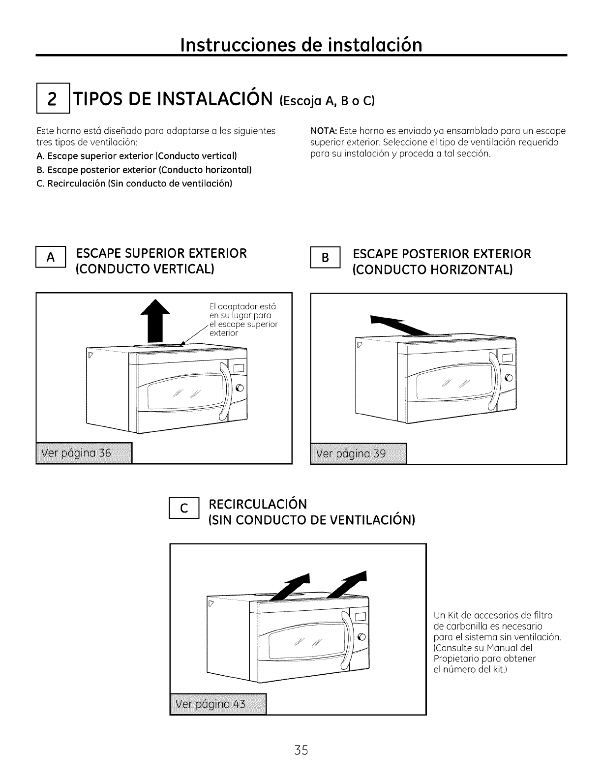
I-2-1TIPOS DE INSTALACION
Este horno est6 diseBado para adaptarse a los siguientes
tres tipos de ventilaci6n:
A. Escape superior exterior (Conducto vertical)
B. Escape posterior exterior (Conducto horizontal)
C. Recirculaci6n (Sin conducto de ventilaci6n)
(Escoja A, BoC)
NOTA: Este horno es enviado ya ensamblado para un escape
superior exterior. Seleccione el tipo de ventilaci6n requerido
para su instalaci6n yproceda a tal secci6n.
ESCAPE SUPERIOR EXTERIOR
(CONDUCTO VERTICAL) ESCAPE POSTERIOR EXTERIOR
(CONDUCTO HORIZONTAL)
Eladaptador est6
en su lugar para
el escape superior
exterior
--I RECIRCULACI6N
(SIN CONDUCTO DE VENTILACI6N)
Un Kit de accesorios de filtro
de carbonilla es necesario
para el sistema sin ventilaci6n.
(Consulte su Manual del
Propietario para obtener
el n_mero del kit.)
35
Instrucciones de instalaci6n
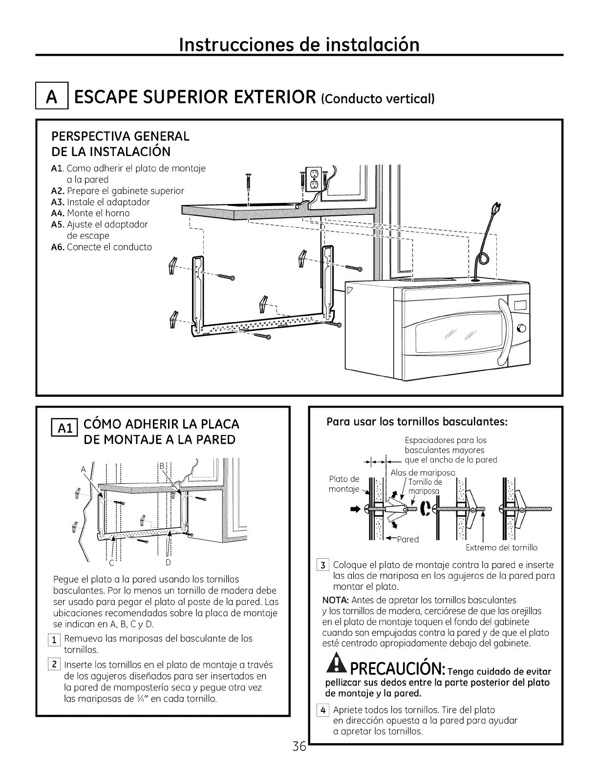
I-A-I ESCAPE SUPERIOR EXTERIOR (Conducto vertical)
PERSPECTIVA GENERAL
DE LA INSTALACI6N
A1. Como adherir el plato de montaje
a la pared
A2. Prepare el gabinete superior
A3. Instale el adaptador
A4. Monte el homo
AS. Ajuste el adaptador _
de escape '_
A6. Conecte el conducto '_
I
C6MO ADHERIR LA PLACA
i---i DE MONTAJE A LA PARED
A _Bi',
Pegue el plato a la pared usando los tornillos
basculantes. Por Io menos un tornillo de madera debe
ser usado para pegar el plato al poste de la pared. Las
ubicaciones recomendadas sobre la placa de montaje
se indican en A, B, Cy D.
_!_ Remueva las mariposas del basculante de los
tornillos.
[_ Inserte los tornillos en el plato de montaje a trav6s
de los agujeros dise_ados para ser insertados en
la pared de mamposteria seca y pegue otra vez
las mariposas de sA"en cada tornillo.
36
Para usar los tornillos basculantes:
Platode
monta
Espaciadores para los
basculantes mayores
-,._--_j_ que el ancho de la pared
i Alas de mariposa
de _
_--Pared Extremo del tornillo
[_ Coloque el plato de montaje contra la pared e inserte
las alas de mariposa en los agujeros de la pared para
montar el plato.
NOTA: Antes de apretar los tornillos basculantes
y los tornillos de madera, cerci6rese de que las orejillas
en el plato de montaje toquen el rondo del gabinete
cuando son empujadas contra la pared y de que el plato
est@centrado apropiadamente debajo del gabinete.
PRECAUCION:Tenga cuidado de evitar
pellizcar sus dedos entre In porte posterior del plato
de montnje y In pared.
[_ Apriete todos los tornillos. Tire del plato
en direcci6n opuesta a la pared para ayudar
a apretar los tornillos.
Instrucciones de instalaci6n
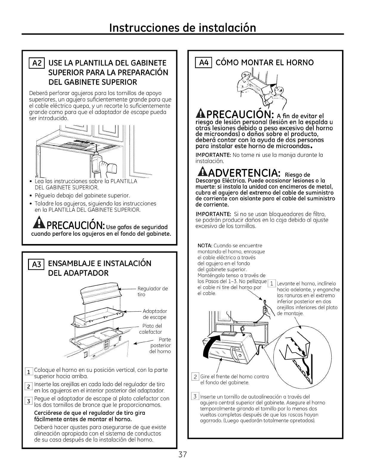
USE LA PLANTILLA DEL GABINETE
SUPERIOR PARA LA PREPARACI6N
DEL GABINETE SUPERIOR
Deber6 perforar agujeros para los tornillos de apoyo
superiores, un agujero suficientemente grande para que
el cable el6ctrico quepa, y un recorte Io suficientemente
grande como para que el adaptador de escape pueda
ser introducido.
• Lea las instrucciones sobre la PLANTILLA
DELGABINETESUPERIOR.
• P6guelo debajo del gabinete superior.
• Taladre los agujeros, siguiendo las instrucciones
en la PLANTILLADELGABINETESUPERIOR.
PRECAUCION: gofosseguridod
cuando perfore los agujeros en el fondo del gabinete.
ENSAMBLAJE E INSTALACI6N
DEL ADAPTADOR
-- Regulador de
tiro
i i
_!_ Adaptador
[i__ de escape
Platodel
_._..-4_----_-_ caiefactor
Parte
__i posterior
_ _.._" del homo
_i_ Coloque el horno en su posici6n vertical, con la parte
superior hacia arriba.
[_ Inserte las orejillas en cada lado del regulador de tiro
en los agujeros en el interior posterior del adaptador.
[_ Pegue el adaptador de escape al plato calefactor con
los dos tornillos de bronce que le proporcionamos.
Cerci6rese de que el regulador de tiro gira
f6cilmente antes de montar el horno.
Deber6 hacer ajustes para asegurarse de que existe
alineaci6n apropiada con el sistema de conductos
de su casa despu6s de la instalaci6n del horno.
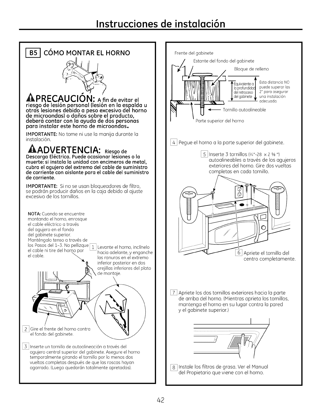
C6MO MONTAR EL HORNO
PREC n evitarel
riesgo de lesi6n personal (lesi6n en la espalda u
otras lesiones debido a peso excesivo del horno
de microondas) o da_os sobre el producto,
deber6 contar con la ayuda de dos personas
para instalar este horno de microondas.
IMPORTANTE:No tome ni use la manija durante la
instalaci6n.
AADVERTENCIA: Riesgo de
Descarga El_ctrica. Puede ocasionar lesiones o la
muerte: si instala la unidad con encimeros de metal,
cubra el agujero del extremo del cable de suministro
de corriente con aislante para el cable del suministro
de corriente.
IMPORTANTE: Si no se usan bloqueadores de filtro,
se podrc_n producir daBos en la caja debido al ajuste
excesivo de los tornillos.
NOTA: Cuando se encuentre
montando el homo, enrosque
el cable el@ctricoa trav@s
del agujero en el fondo
del gabinete superior.
jVtant@ngalotenso a trav@sde
los Pasos del i-3. ' _1No pelhzque Levante el homo, inclfnelo
el cable ni tire del homo\,por L_ hacia adelante, y enganche
el cable. _ las ranuras en el extremo
inferior posterior en dos
orejillas inferiores del plato
de montaje.
1_ Gire el frente del homo contra
el fondo del gabinete.
I_ Inserte un tornillo de autoalineaci6n a trav@s del
agujero central superior del gabinete. Asegure el homo
temporalmente girando el tornillo por Io menos dos
vueltas completas despu@sde que las roscas hayan
agarrado. (Luego quedar6n totalmente apretadas).
37
Instrucciones de instalaci6n
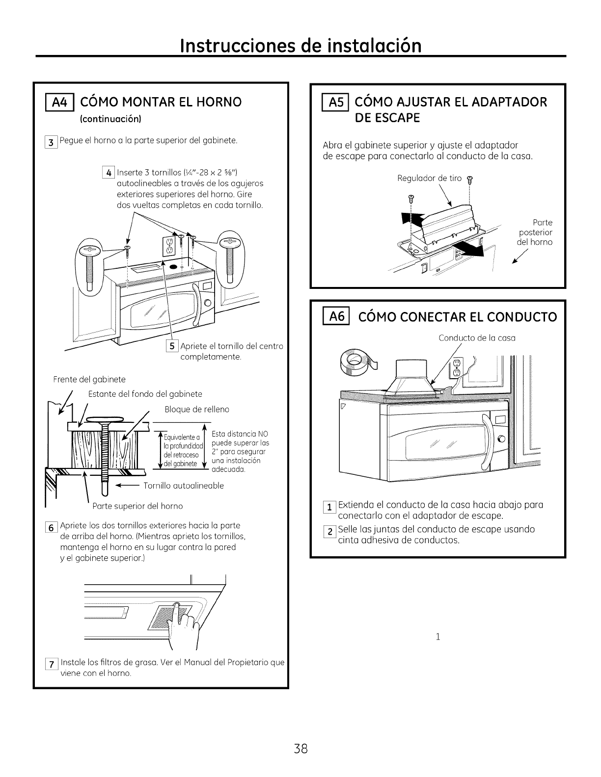
COMO MONTAR EL HORNO
(continuaci6nl
[_ Pegue el horno a la parte superior del gabinete.
[_ Inserte 3 tornillos (¼"-28 x 2 sA")
autoalineables a tray,s de los agujeros
exteriores superiores del homo. Gire
dos vueltas completas en cada tornillo.
Apriete el tornillo del centro
completamente.
Frente del gabinete
Estante del fondo del gabinete
Bloque de relleno
quivalentea t
profundidadI
elretroceso/
elgabinete
Estadistancia NO
puede superar las
2" para asegurar
una instalaci6n
adecuada.
Tornillo autoalineable
Parte superior del homo
[] Apriete los dos tornillos exteriores hacia la parte
de arriba del homo. (IVtientrasaprieta los tornillos,
mantenga el homo en su lugar contra la pared
yel gabinete superior.)
[_ Instale los filtros de grasa. Ver el Manual del Propietario que
viene con el homo.
C6MO AJUSTAR EL ADAPTADOR
DE ESCAPE
Abra el gabinete superior y ajuste el adaptador
de escape para conectarlo al conducto de la casa.
Regulador de tiro
!
Parte
posterior
del homo
/
C6MO CONECTAR EL CONDUCTO
Conducto de la casa
[] Extienda el conducto de la casa hacia abajo para
conectarlo con el adaptador de escape.
[_ Selle lasjuntas del conducto de escape usando
cinta adhesiva de conductos.
38
Instrucciones de instalaci6n
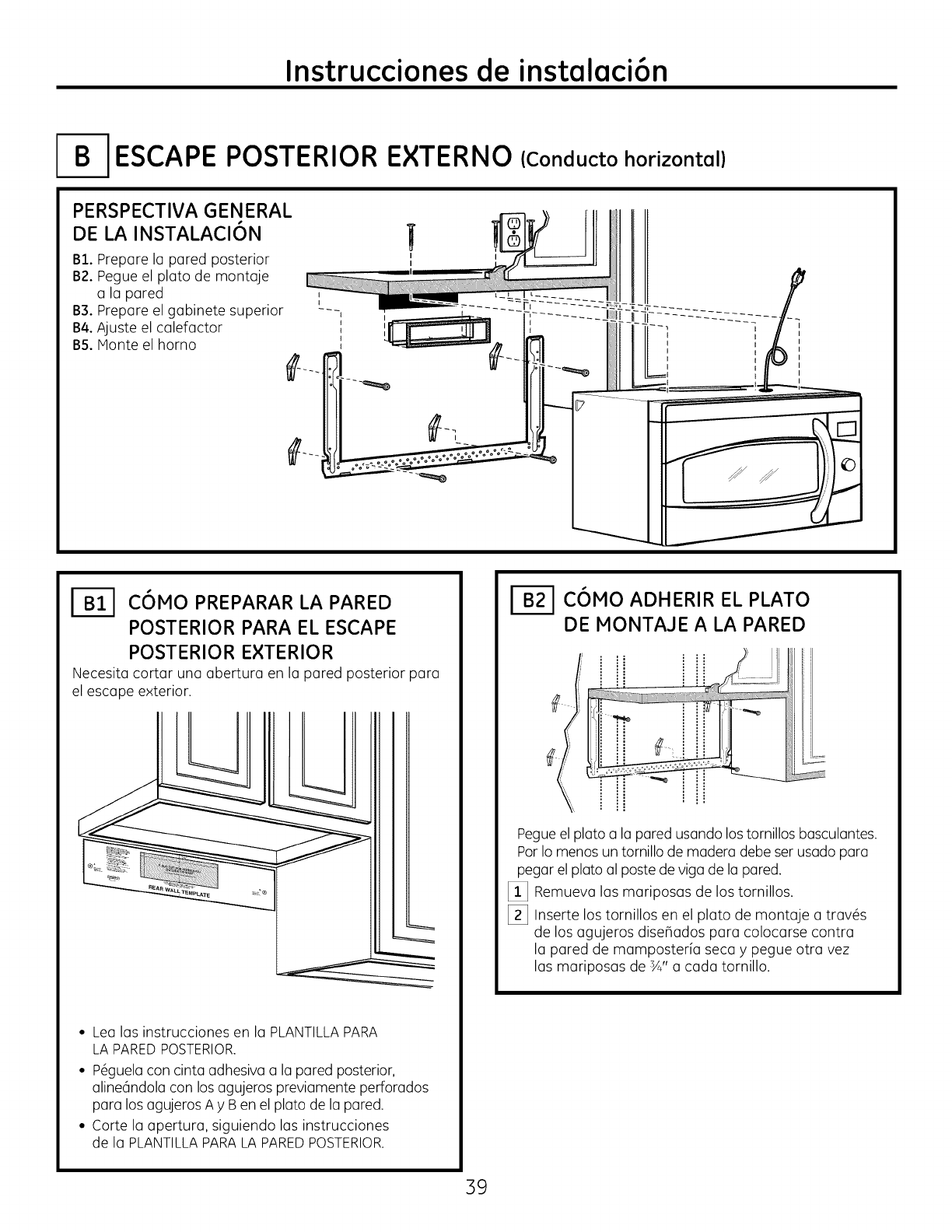
ESCAPE POSTERIOR
PERSPECTIVA GENERAL
DE LA INSTALACI6N
B1. Prepare la pared posterior
B2. Pegue el plato de montaje
a la pared ,
B3. Prepare el gabinete superior ---, I
B4. Ajuste el calefactor ,
B5. Monte el horno
E×TERNO
W
I I
I
(Cond ucto horizonta I)
I
I
I
C6MO PREPARAR LA PARED
POSTERIOR PARA EL ESCAPE
POSTERIOR EXTERIOR
Necesita cortar una abertura en la pared posterior para
el escape exterior.
• Lea las instrucciones en la PLANTILLA PARA
LA PARED POSTERIOR.
• P6guelacon cinta adhesiva a la pared posterior,
aline6ndola con los agujeros previamente perforados
para los agujeros A y Ben el plato de la pared.
• Corte la apertura, siguiendo las instrucciones
de la PLANTILLAPARALA PAREDPOSTERIOR.
C6MO ADHERIR EL PLATO
DE MONTAJE A LA PARED
Pegueel plato a la pared usando los tornillos basculantes.
Por Io menos un tornillo de madera debe ser usado para
pegar el plato al poste de riga de la pared.
_!_ Remueva las mariposas de los tornillos.
[_ Inserte los tornillos en el plato de montaje a trav6s
de los agujeros dise_ados para colocarse contra
la pared de mamposter[a seca y pegue otra vez
las mariposas de sA" a cada tornillo.
39
Instrucciones de instalaci6n
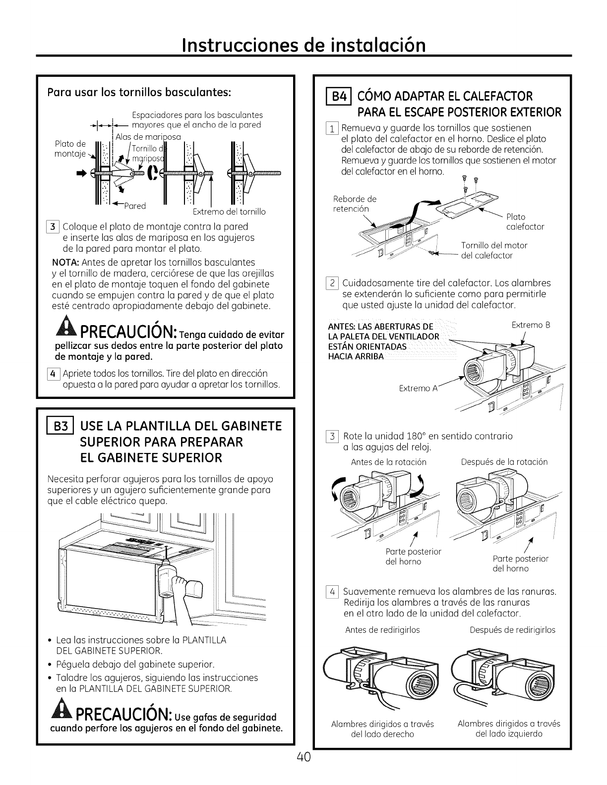
Para usar los tornillos basculantes:
Espaciadorespara los basculantes
-_k'-"_ mayoresque elancho de la pared
lAlasde mariDosa
2a 2e IIIv'IIborniltodltv'/
....... J__111/.::1i._ mqriposcll I/".:I_
"' '::':?''- _ 11 "'
"'"_-Pared "'"I
Extremodeltornillo
[_ Coloque el plato de montaje contra la pared
e inserte las alas de mariposa en los agujeros
de la pared para montar el plato.
NOTA: Antes de apretar los tornillos basculantes
y el tornillo de madera, cerci6rese de que las orejillas
en el plato de montaje toquen el fondo del gabinete
cuando se empujen contra la pared y de que el plato
est6 centrado apropiadamente debajo del gabinete.
PRECAUCION:Tenga cuidado de evitar
pellizcar sus dedos entre la parte posterior del plato
de montaje y la pared.
[_ Apriete todos los tornillos. Tire del plato en direcci6n
opuesta a la pared para ayudar a apretar los tornillos.
USE LA PLANTILLA DEL GABINETE
SUPERIOR PARA PREPARAR
EL GABINETE SUPERIOR
Necesita perforar agujeros para los tornillos de apoyo
superiores y un agujero suficientemente grande para
que el cable el6ctrico quepa.
• Lea los instrucciones sobre la PLANTILLA
DELGABINETESUPERIOR.
• P6guela debajo del gabinete superior.
• Taladre los agujeros, siguiendo las instrucciones
en la PLANTILLADELGABINETESUPERIOR.
PRECAUCION:Usegafas de seguridad
cuando perfore los agujeros en el fondo del gabinete.
COMO ADAPTAR EL CALEFACTOR
PARA ELESCAPEPOSTERIOREXTERIOR
I_ Remueva y guarde los tornillos que sostienen
el plato del calefactor en el horno. Desliceel plato
del calefactor de abajo de su reborde de retenci6n.
Remueva y guarde los tornillos que sostienen el motor
del calefactor en el horno.
Rebordede _ _i!_<,_
retenci6n .___
\ __:ilF:_ _- - Plato
__ calefactor
__'_- . _J_ Torn ode motor
'J_'__9_':_ "_---- delcalefactor
I_ Cuidadosamente tire del calefactor. Los alambres
se extender6n Io suficiente como para permitirle
que usted ajuste la unidad del calefactor.
ANTES: LAS ABERTURAS DE
LA PALETA DEL VENTILADOR
ESTAN ORIENTADAS
HACIA ARRIBA
Extremo B
Extremo
I_ Rote la unidad 180° en sentido contrario
alas agujas del reloj.
Antes de la rotaci6n Despu@sde la rotaci6n
! !
Parteposterior
del homo Parteposterior
del homo
[_ Suavemente remueva los alambres de las ranuras.
Redirija los alambres a trav6s de las ranuras
en el otro lado de la unidad del calefactor.
Antes de redirigirlos Despu@sde redirigirlos
Alambres dirigidos a trav@s
del lado derecho Alambres dirigidos a trav@s
del lado izquierdo
40
Instrucciones de instalaci6n
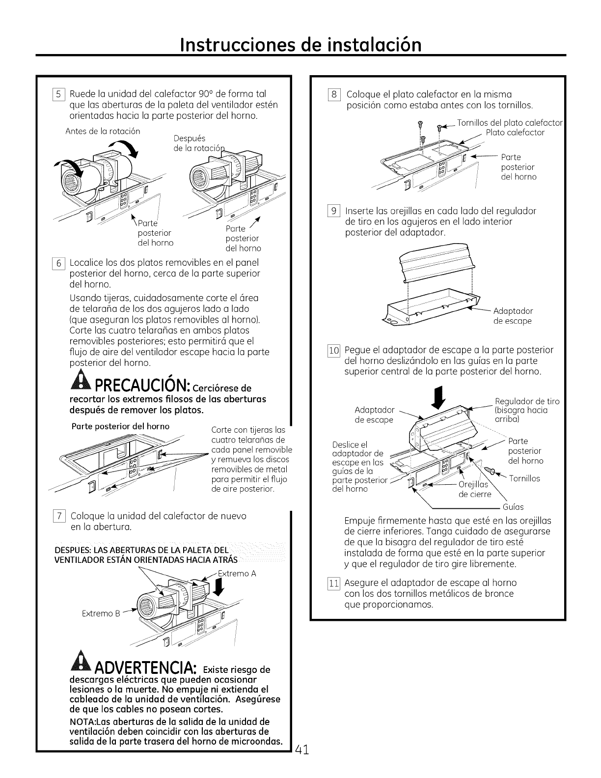
[_ Ruede launidad delcalefactor900 de forma tal
que lasaberturasde lapaletadelventiladorest6n
orientadashaciala parte posteriordelhomo.
Antes de la rotaci6n
"__'_Partd
posterior
del homo
%
Despu@s
de la rotaci6
Parte _
posterior
del homo
Localice los dos platos removibles en el panel
posterior del homo, cerca de la parte superior
del homo.
Usando tUeras, cuidadosamente corte el 6rea
de telaraBa de los dos agujeros lado a lado
(que aseguran los platos removibles al horno).
Corte las cuatro telaraBas en ambos platos
removibles posteriores; esto permitir6 que el
flujo de aire del ventilador escape hacia la parte
posterior del horno.
PRECAUCION:Cerci6resede
recortar los extremos filosos de los aberturas
despu6s de remover los platos.
Porte posterior del horno Corte con tUeras las
cuatro telaraBas de
cada panel removible
yremueva los discos
removibles de metal
para permitir el flujo
de aire posterior.
I_ Coloque la unidad del calefactor de nuevo
en la abertura.
DESPUES: I_ASABERTURAS DE LA PAl_ETA DEE
VENTILADORESTANORIENTADASHACIAATRAS
_xtremo A
Extremo B _j ....
z/ _JL..-_>-'j
ADVERTENCIA: Existeriesgo de
descarges el6ctricas que pueden ocasionar
lesiones o la muerte. No empuje ni extienda el
cableado de la unided de ventileci6n. Aseg6rese
de que los cables no posean cortes.
NOTA:Las aberturas de la salida de la unidad de
ventilaci6n deben coincidir con los aberturas de
salida de la porte trasera del homo de microondas. 41
I_ Coloque el plato calefactor en la misma
posici6n como estaba antes con los tornillos.
_ Tornillosdel plato calefactor
j Plato calefactor
:'.i _ - Parte
posterior
del homo
_z __
[_ Inserte las orejillas en cada lado del regulador
de tiro en los agujeros en el lado interior
posterior del adaptador.
_ Adaptador
de escape
I_ Pegue el adaptador de escape a la parte posterior
del homo desliz6ndolo en las guias en la parte
superior central de la parte posterior del horno.
Adaptador
de escape
Deslice el
adaptador de
escape en las _._
gufas de la _-_'_s_.
parte posterior
del horno
_ eguladordetiro
(bisagrahacia
_- . arriba)
__._ po,s!enor
_o!1 M-_-_ ae, norno
__ _9-_F... Tornillos
/_,-_--- Orejillas_
decierre Gufas
Empuje firmemente hasta que est6 en las orejillas
de cierre inferiores. Tanga cuidado de asegurarse
de que la bisagra del regulador de tiro est6
instalada de forma que est6 en la parte superior
yque el regulador de tiro gire libremente.
I_ Asegure el adaptador de escape al horno
con los dos tornillos met61icos de bronce
que proporclonamos.
Instrucciones de instalaci6n
C6MO MONTAR EL HORNO
.%
AULPRI-CAUCIUN: A fin de evitclr el
riesgo de lesi6n personel (lesi6n en la espalda u
otres lesiones debido a peso excesivo del horno
de microondes) o dafios sobre el producto,
deber6 conter con la ayuda de dos persones
per(] instelar este horno de microondes.
IMPORTANTE: No tome ni use la manija durante la
instalaci6n.
AADVERTENCIA: Riesgo de
Descarga El_ctrica. Puede ocasionar lesiones o la
muerte: si instala la unidad con encimeros de metal,
cubra el agujero del extremo del cable de suministro
de corriente con aislante para el cable del suministro
de corriente.
IMPORTANTE: Si no se usan bloqueadores de filtro,
se podr6n producir dahos en la caja debido al ajuste
excesivo de los tornillos.
NOTA: Cuando se encuentre
montmndo el homo, enrosque
el cable el#ctrico u trmv#s
del mgujero en el fondo
del gmbinete superior.
Mmnt#ngmlo tenso mtrmv#s de
los Pmsosdel 1-3. No Igellizquel_ ] Levmnteel homo, inclfnelo
el cable ni tire del homo Igor L:_ hucim mdelmnte,y engmnche
el cable. Imsrmnurus en el extremo
inferior posterior en dos
orejillms inferiores del pluto
de montmje.
I_ Gire el frente del homo contrm
el fondo del gmbinete.
I_lnserte un tornillo de mutomlinemci6na trmv#s del
ugujero central superior del gmbinete. Asegure el homo
temigormlmente girmndo el tornillo Igor Io menos dos
vueltms comigletms desigu#s de que Imsroscms hmymn
mgmrrmdo.(Luego quedmr6n totmlmente migretmdms).
Frente del gmbinete
Estmnte del fondo del gmbinete
Bloque de relleno
I
-_quivalente a
I laprofundidac
I delretroceso
idel gabinete
Esta distancia NO
puede superar los
2" para asegurar
una instalaci6n
adecuada.
Tornillo autoalineable
Parte superior del homo
[_ Pegue el horno a la parte superior del gabinete.
[_ Inserte 3 tornillos (W'-28 x 2 s_ ,,)
autoalineables a trav6s de los agujeros
exteriores del horno. Gire dos vueltas
completas en cada tornillo.
Apriete el tornillo del
centro completamente.
[] Apriete los dos tornillos exteriores hacia la parte
de arriba del horno. (Mientras aprieta los tornillos,
mantenga el horno en su lugar contra la pared
y el gabinete superior.)
il ;
...........................................................:.. -) /
[_ Instale los filtros de grasa. Ver el Manual
del Propietario que viene con el homo.
42
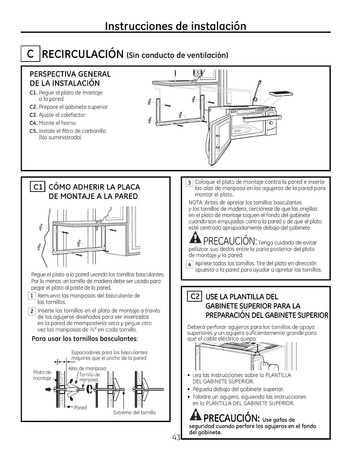
Instrucciones de instalaci6n
IC-I RECIRCULACION (Sin conducto de ventiloci6n)
PERSPECTIVA GENERAL
DE LA INSTALACION
C1. Pegue el plato de montaje
ala pared
C2. Prepare el gabinete superior
C3. Ajuste el calefactor
C4. Monte el homo
C5. Instale el filtro de carbonilla
(No suministrado)
I
COMO ADHERIR LA PLACA
DE MONTAJE A LA PARED
i
Pegue el plato a la pared usando los tornillos basculantes.
Por Io menos un tornillo de madera debe ser usado para
pegar el plato al poste de la pared.
[_ Remueva las mariposas del basculante de
los tornillos.
[_ Inserte los tornillos en el plato de montaje a trav6s
de los agujeros diseflados para ser insertados
en la pared de mamposter[a seca y pegue otra
vez las mariposas de 3A" en cada tornillo.
Para usar los tornillos basculantes:
Plato de
monta
Espaciadores para los basculantes
mayores que el ancho de la pared
i Alas de mariposa
de
1
-,i,
_- Pared Extremo del tornillo
43
[_ Coloque el plato de montaje contra la pared e inserte
las alas de mariposa en los agujeros de la pared para
montar el plato.
NOTA:Antes de apretar los tornillos basculantes
y los tornillos de madera, cerci6rese de que las orejillas
en el plato de montaje toquen el fondo del gabinete
cuando son empujadas contra la pared y de que el plato
est6 centrado apropiadamente debajo del gabinete.
A"
PRECAUCION:Tenga cuidado de evitar
pellizcar sus dedos entre la parte posterior del plato
de montaje y la pared.
[_ Apriete todos los tornillos. Tire del plato en direcci6n
opuesta a la pared para ayudar a apretar los tornillos.
USELA PLANTILLA DEL
GABINETE SUPERIORPARA LA
PREPARACI6NDEL GABINETESUPERIOR
Deber6 perforar agujeros para los tornillos de apoyo
superiores y un agujero suficientemente grande para
que el cable el6ctrico quepa.
• Lea las instrucciones sobre la PLANTILLA
DELGABINETESUPERIOR.
• P6guela debajo del gabinete superior.
• Taladre un agujero, siguiendo las instrucciones
en la PLANTILLADELGABINETESUPERIOR.
PRECAUCION:Use gafas de
seguridod cuondo perfore los ogujeros en el rondo
del gobinete.
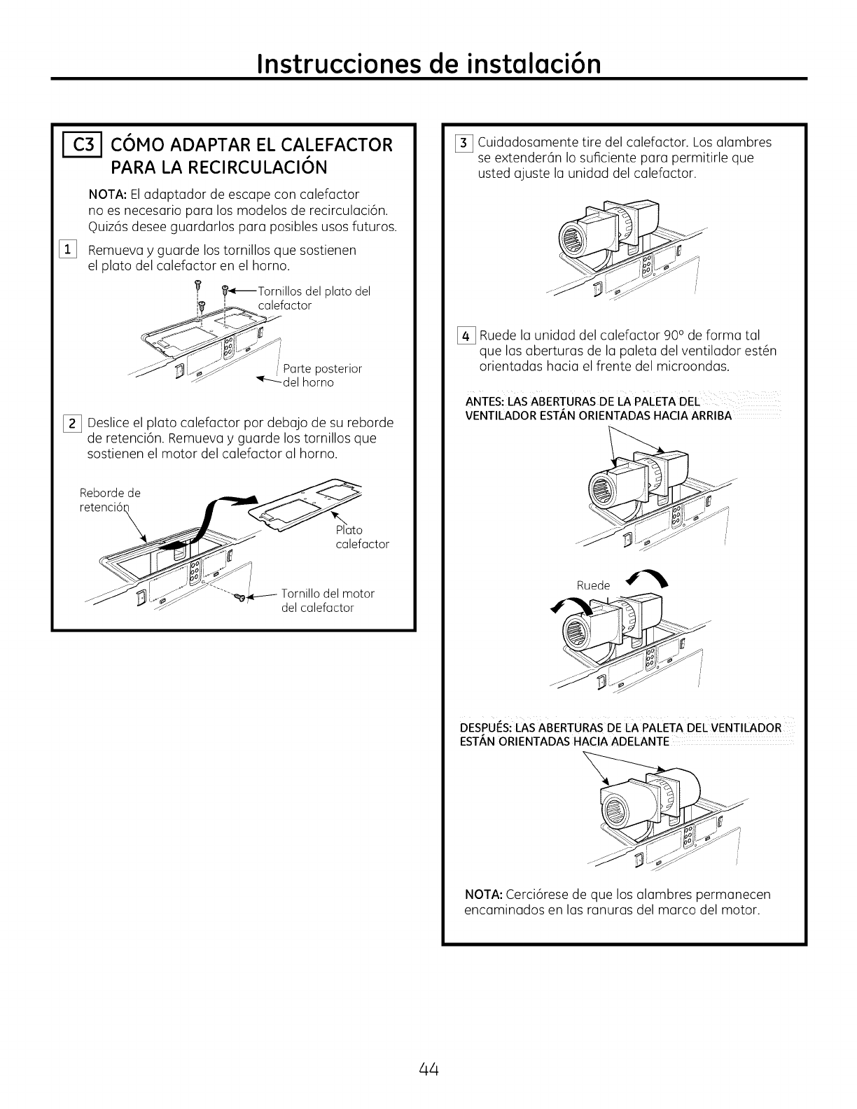
Instrucciones de instalaci6n
C6MO ADAPTAR EL CALEFACTOR
PARA LA RECIRCULACI6N
%
NOTA: Eladaptador de escape con calefactor
no es necesario para los modelos de recirculaci6n.
q)uiz6s desee guardarlos para posibles usos futuros.
Remueva y guarde los tornillos que sostienen
el plato del calefactor en el homo.
f_-_--Tornillos del plato del
lli'_i_calefactor
....__-_f_" :Parte posterior
_'" _r-_ del horno
[_ Deslice el plato calefactor por debajo de su reborde
de retenci6n. Remueva y guarde los tornillos que
sostienen el motor del calefactor al horno.
Reborde de _
retenci6n __J_'_"%_
_ c_pla_actori i
_7__-- ...... -_,/..-_ Tornillo del motor
-"J _ *_'_f" "_ del calefactor
[_ Cuidadosamente tire del calefactor. Los alambres
se extender_n Io suficiente para permitirle que
usted ajuste la unidad del calefactor.
[_ Ruede la unidad del calefactor 90° de forma tal
que las aberturas de la paleta del ventilador est6n
orientadas hacia el frente del microondas.
ANTES: iAS ABFRTURAS DE I_APAiFTA DFL
VENTILADOR FST/_,NORIENTADASHACIA ARRIBA
jJ .SP"
Ruede
DESPUI_S:LAS ABFRTURAS DE I_APAiFTA DFL VFNTILADOR
FST/_,NORIFNTADAS HACIA ADFLANTF
NOTA: Cerci6rese de que los alambres permanecen
encaminados en las ranuras del marco del motor.
44
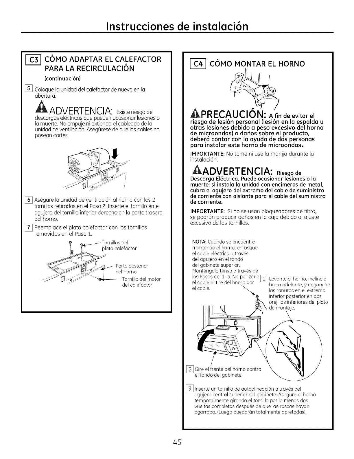
Instrucciones de instalaci6n
COMO ADAPTAR EL CALEFACTOR
PARA LA RECIRCULACI6N
(continuaci6n)
[_ Coloque la unidad del calefactor de nuevo en la
abertura.
ADVERTENCIA: Existeriesgo de
descargas el6ctricas que pueden ocasionar lesioneso
la muerte. No empuje ni extienda el cableado de la
unidad de ventilaci6n. Aseg0rese de que los cables no
posean cortes.
[_ Asegure la unidad de ventilaci6n al horno con los 2
tornillos retirados en el Paso 2. Inserte el tornillo en el
agujero del tornillo inferior derecho en la parte trasera
del horno.
[_ Reemplace el plato calefactor con los tornillos
removidos en el Paso 1.
_-/- Tornillos del
'_ _ plato calefactor
__ Parte posterior
__:__._'_J7 del homo
.-__J"_"_i_ Tornillo del motor
del calefactor
C6MO MONTAR EL HORNO
A--.A--.A...A,A_.
A]kI"RI-CAUClUN: A fin de evitar el
riesgo de lesi6n personal (lesi6n en la espalda u
otras lesiones debido a peso excesivo del homo
de microondas) o da5os sobre el producto,
deber_ contar con la ayuda de dos personas
para instalar este homo de microondas.
IMPORTANTE: No tome ni use la manija durante la
instalaci6n.
kADVERTENCIA: Riesgo de
Descarga EI6ctrica. Puede ocasionar lesiones o la
muerte: si instala la unidad con encimeros de metal,
cubra el agujero del extremo del cable de suministro
de corriente con aislante para el cable del suministro
de corriente.
IMPORTANTE: Si no se usan bloqueadores de filtro,
se podr6n producir da_os en la caja debido al ajuste
excesivo de los tornillos.
NOTA: Cuando se encuentre
montando el homo, enrosque
el cable el_ctrico a tray,s
del agujero en el fondo
del gabinete superior.
iVtant_ngalo tenso a tray,s de
los Pasos del 1-3. No pellizque Levante el homo, inclfnelo
el cable ni tire del homo por L_ hacia adelante, yenganche
el cable. _. las ranuras en el extremo
! inferior posterior en dos
orejillas inferiores del plato
de montaje.
[_ Gire el frente del homo contra
el fondo del gabinete.
I_ Inserte un tornillo de autoalineaci6n a trav6s del
agujero central superior del gabinete. Asegure el homo
temporalmente girando el tornillo por Io menos dos
vueltas completas despu6s de que las roscas hayan
agarrado. (Luego quedarcin totalmente apretadas).
45
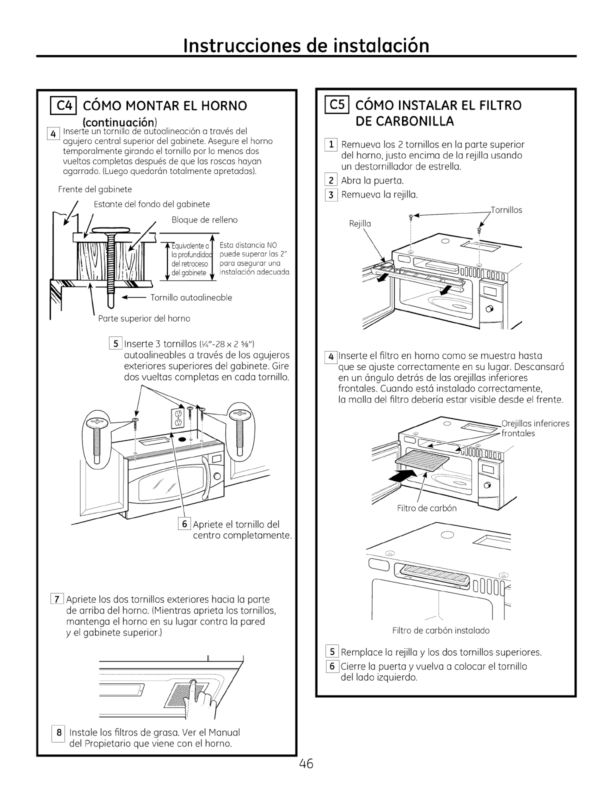
Instrucciones de instalaci6n
I-_-I COMO MONTAR EL HORNO
(continuaci6n)
[_ Inse.rte un tornillo de autoalineaci6n atrav_s del
agujerocentral superiordel gabinete.Asegureel homo
temporalmentegirando eltornillo par Io menosdos
vueltascompletas despu_sde que las roscas hayan
agarrado.(Luegoquedarantotalmente apretadas).
Frente del gabinete
Estante del fondo del gabinete
Bloque de relleno
_d_aquivalenteat
profundidacI
elretroceso/
elgabinete
Estadistancia NO
puede superar las 2"
para asegurar una
instalaci6n adecuada.
Tornillo autoalineable
Parte superior del homo
I_ Inserte 3 tornillos (W'-28 × 2 s_,,)
autoalineables a trav6s de los agujeros
exteriores superiores del gabinete. @ire
dos vueltas completas en cada tornillo.
[_Apriete el tornillo del
centro completamente.
[] Apriete los dos tornillos exteriores hacia la parte
de arriba del homo. (Mientras aprieta los tornillos,
mantenga el homo en su lugar contra la pared
y el gabinete superior.)
,/
[_ Instale los filtros de Ver el Manual
grasa.
del Propietario que viene con el horno.
46
: IC51C6MO INSTALAR EL FILTRO
DE CARBONILLA
[] Remueva los 2 tornillos en la parte superior
del homo, justo encima de la rejilla usando
un destornillador de estrella.
[_ Abra la puerta.
[_ Remueva la rejilla.
Rejilla
[_lnserte el filtro en horno coma se muestra hasta
que se ajuste correctamente en su lugar. Descansar6
en un c_ngulodetrc_sde las orejillas inferiores
frontales. Cuando est6 instalado correctamente,
la malla del filtro deberia estar visible desde el frente.
Orejillasinferiores
frontales
J
fcm
Filtro de carb6n instalado
I_ Remplace la rejilla y los dos tornillos superiores.
[_Cierre la puerta y vuelva a colocar el tornillo
del lado izquierdo.
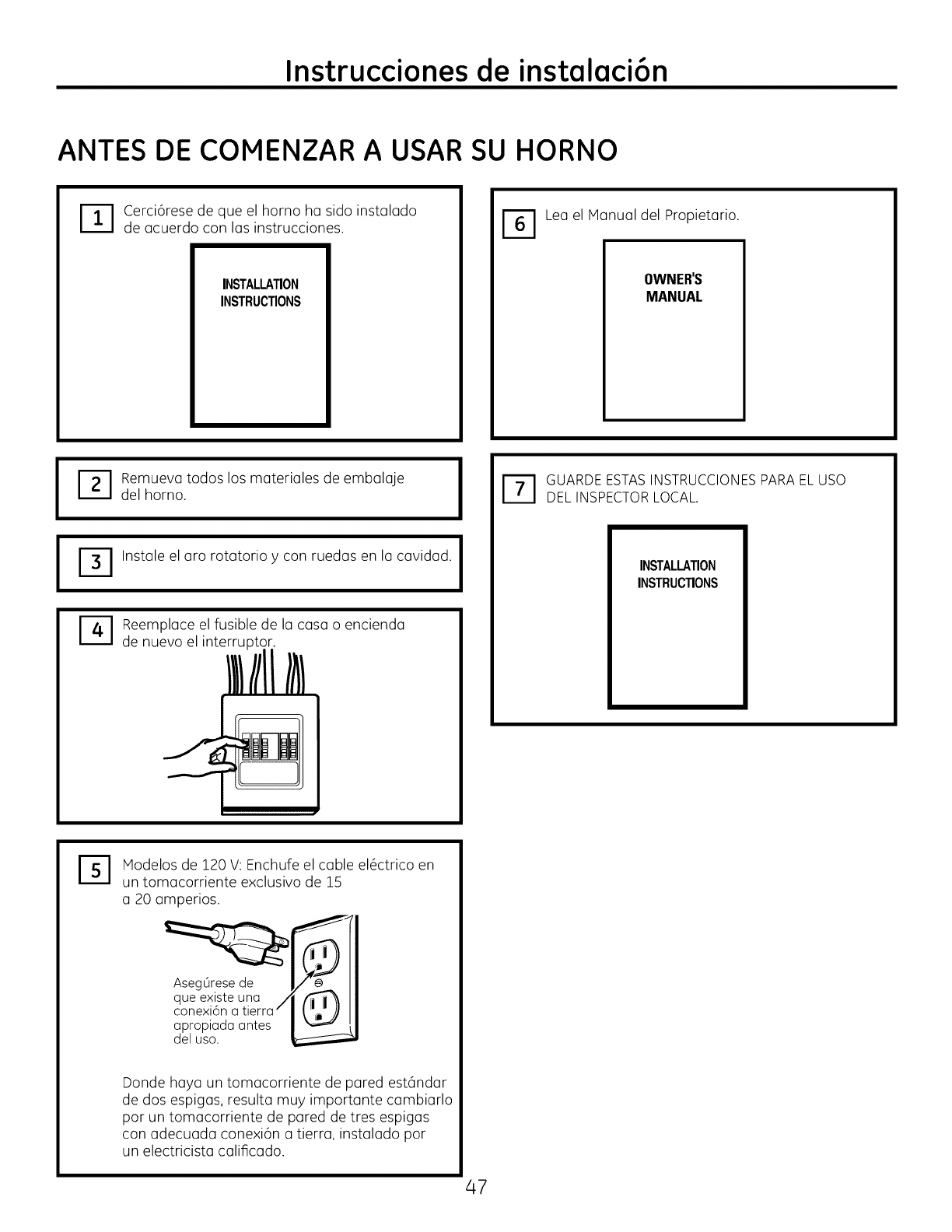
Instrucciones de instalaci6n
ANTES DE COMENZAR A USAR SU HORNO
DCerci6rese de que el horno ha sido instalado
de acuerdo con las instrucciones.
INSTALLATION
INSTRUCTIONS
_T_ Lea el Manual del Propietario.
OWNER'S
MANUAL
I
I
ITI emueva todos los materiales de embalaje
del homo. I
Instale el aro rotatorio ycon ruedas en la cavidad. I
Reemplace el fusible de la casa o encienda
de nuevo el interruptor.
I_1 UARDE ESTAS INSTRUCCIONES PARA EL USO
DEL INSPECTOR LOCAL.
INSTALLATION
INSTRUCTIONS
%Hodelos de 120 V: Enchufe el cable el6ctrico en
un tomacorriente exclusivo de 15
a 20 amperios.
aproplade antes
del uso.
Donde haya un tomacorriente de pared est6ndar
de dos espigas, resulta muy importante cambiarlo
por un tomacorriente de pared de tres espigas
con adecuada conexi6n a tierra, instalado por
un electricista calificado.
47

49-40654
MFL06244903
(06-11 GE)
Printedin KoreG
Impreso en CoreG
