GE GBS20HBSAWW User Manual REFRIGERATOR S SERIES Manuals And Guides L0501053
GE Bottom Mount Refrigerator Manual L0501053 GE Bottom Mount Refrigerator Owner's Manual, GE Bottom Mount Refrigerator installation guides
User Manual: GE GBS20HBSAWW GBS20HBSAWW GE REFRIGERATOR S SERIES - Manuals and Guides View the owners manual for your GE REFRIGERATOR S SERIES #GBS20HBSAWW. Home:Kitchen Appliance Parts:GE Parts:GE REFRIGERATOR S SERIES Manual
Open the PDF directly: View PDF ![]() .
.
Page Count: 43
wvvvv.GEAppliances.com
N
©
Safety InsTtrudions ........... 9 3
Operating Instru_tions
Additional Features ............. 9
Automatic Icemaker . .......... 19
Controls .................... 4-6
Crispers and Pans ............. 10
Freezer ...................... 11
Shelves and Bins ............. 8, 9
_'ater Filter ................... 7
Care and Cleaning ........ 13-15
Installation Instructions
Installing the Refligerator . . . .17-91
Installing the _4'ater Line ..... 98-30
Preparing to Install
the Refligerator . .............. 16
Removing and Replacing the
Freezer Drawer ............ 99, 93
Reversing the Door Swing .... 24-27
Troubleshooting Tips ....... 31-35
Normal Operating Sounds ...... 31
Consumer Support
Consumer Support ..... Back (',over
Performance Data Sheet ........ 41
Product Registration ........ 37, 38
Warranty for Canadian
Customers ................... 39
_'arrantv for U.S. Customers ..... 40
Models 20 and22
Cong_lateur inf>rieur
R frig&ateurs
La section fran_aise commence a la page 43
Congelador inferior
Refrigeradores
La seccionen espa#olempieza en lapagina 83
Write the model and serial
numbers here:
Model #
Serial #
Find these numbex_ on a label
on the right side, near the top of
the refl'igerator compartment.
3828JL8012C 197D4618PO04 49-60355 !2-04 Jfl

IMPORTANTSAFETYINFORMATION.
READALLINSTRUCTIONSBEFOREUSING.
AWARNING!
Use this appliance only for its intended purpose as described in this Owner's Manual.
SAFETYPRECAUTIONS
When using electrical appliances, basic safety precautions should be followed, including the following:
This refl'igerat )r must be i)roi)erl ) installed
and located in accordance with the Installation
hlstrucfions before it is used.
Do not allow children to climb, stand or hang
on the shelves in the refl-Jgeratm: They could
damage the refl-Jgerator and seriously iqjm'e
themselves.
Do not touch the cold sm'fi_ces in the fl'eezer
compartment when hands are damp or wet.
Skin max stick to these extremely cold SUll'ilces.
_ Do not store or use gasoline or other flammable
wq)ors and liquids in the vicinity of this or anv
other appliance.
Keep finge_ out of the "pinch point" areas;
clearances between the doms and between
the (loo_s and cabinet are necessarily small.
Be carefld closing doms when children are
in the area.
In refl'Jgeratms Mth automatic icemake_s,
avoid contact with the moving parts of the
ejector mechanism, or with the heating element
that releases the cubes. Do not place finge_s or
hands on the automatic icemaking mechanism
while the reti-Jgerator is plugged in.
Uni)lug the reflJgerator befin'e cleaning and
making repairs.
NOTE: Westrong/}/recommendthat any servicingbe
performed by a quadded individual
Setting either or both controls to 0(off) does
not remove power to the light circuit.
Do not refl'eeze fl'ozen foods which have
thawed completely.
ADANGER!RISK OFCHILDENTRAPMENT
PROPERDISPOSALOFTHEREFRIGERATOR
Child entrapment and suffocation are not problems
of the i)ast..ltmked or abandoned reli'igeratm_ are
still dangerous...even if they will sit for 'ijust a few
days." If you are getting rid of yore" old refligeratm;
please follow the instructions below to hel I) prevent
accidents.
Before YouThrew Away YourOldRefrigerator
or Freezer:
_ke off the dome.
i.eaxe the shehes in place so that children may
not easih climb inside.
Refrigerants
All refiigeration products contain refiigerants,
which under fe(leral law must be removed prior
to product disI)osal. If you are getting rid of
an old reliigeration product, check with the
company handling the disposal about what
to do.
USEOFEXTENSIONCORDS
Because of potential safety hazards under certain conditions, we strongly recommend against
the use of an extension cord.
However, if you must use an extension cord, it is absoluteh necessary that it be a Ui_-listed (in the United
States) or a CSA certified (in Canada), B-wire ,gr°tmding, t_,l)e appliance extension cord having a gmtmding
t)pe I)hw-, and outlet and that the electrical ratim,., of the cord be 15 amperes (minimum) and 12(1 xolts.

www.GEAppliances.com
a, WARNING!
HOWTOCONNECTELECTRICITY
Do not, under any circumstances, cut or remove the third (ground) prong from the power cord.
For personal safety this appliance must be properly grounded.
The power cord ot this appliance is equipped
with a 3-prong (grounding) plug which mates
with a standard 3-prong (grounding) wall outlet to
minimize the possibili Fot electric shock hazard
fl'om this appliance.
Have the wall outlet and circuit checked by a
qualified electrMan to make sure the outlet is
properly grounded,
_'here a standard 2-prong wall outlet is
encountered, it is your l)e_onal responsibili_' and
obligation to have it replaced with a properly
grounded 3-prong wall outlet.
The reli-igerator should always be plugged into its
own individual electrical outlet which has a w)ltage
rating that matches the rating plate.
This provides the best pedommnce and also
prevents overloading house wiring circuits which
could cause a fire haa_rd fl'om overheated wires.
Never unplug your refrigerator by pulling on the
power cord. Mways grip plug firefly and pull
straight out from the outlet.
]),el)air or replace immediately all power cords that
have become fl'ayed or otherwise damaged. Do not
use a cord that sho_:s cracks or abrasion damage
along its length or at either end.
\4]_en moving the refrigerator away fl'om the
wall, be carefld not to roll over or damage the
power cord.
USEOFADAPTERPLUGS(Adapterpl.gsnotpermittedinCanada)
Because of potential safety hazards under certain conditions, we strongly recommend against
the use of an adapter plug.
However; if win, must use an adapte_, where local
codes pemfit, a temporary connection may be made
to a properly grounded 2-prong wall outlet by use
of a UIAisted adaptor a\_dlable at most local
hardwai'e stoi'es.
The linger slot in the adapter must be aligned Mth
the larger slot in the wall outlet to provide proper
polarity in the connection of the power cord.
When disconnecting the power cord fl'om the
a(lapte_; always hold the adapter in place with one
hand while pulling the power cord plug with the
other hand. If this is not done, the adapter ground
temfinal is ve_' likely to break with repeated use.
If the adapter ground temfinal brea!<% DO NOTUSE
the refl-igerator until a proper ground has been
established.
Attaching the adapter ground terminal to a wall outlet
cover screw does not ground the apphance unless the
cover screw is metal, and not insulated,and the wall
outlet is grounded through the house wiring. Youshould
have the ckcuit checked by a quafified electrician to make
sure the outlet is proper/)/grounded.
READANDFOLLOWTHISSAFETYINFORMATIONCAREFULLY.
SAVETHESEINSTRUCTIONS
3

Aboutthe controlswith
temperaturesettings.(for other models, see next page)
NOTE: Therefrigerator is shipped with protective film coveringthe temperaturecontrols.
If this film was not removedduringinstallation, removeit now
The temperature controls are preset in the factory at 37°1:for the refrigerator compartment
and O°Ffor the freezer compartment. Allow24 hours for the temperature to stabilize to the
preset recommended settings.
The temperature controls can display both the SET temperature as well as the actual
temperature in the refrigerator and freezer. The actual temperature may vary slightly from
the SET temperature based on usage and operating environment.
Setting either or both controls to OFFstops cooling in both the freezer and refrigerator
compartments, but does not shut off electrical power to the refrigerator.
Changing the Temperature
To change the temperature, press and release tile
WARMER or COLDER pad. The Sk'Tlight will con/e
oil and the display will show the set teml)erature.
To change the teml)eramre, tap either the
WARMER or COLDER pad tmfil the desired
temperature is displayed. Refl_igerator temperatures
can be ac!justed between 34°F and 47°F and the
fl'eezer teInl)eratures can be ac!justed between
-(3°F and +8°K
Once the desired temperature has been set,
the temperature display will return to the actual
refl]gei'ator and freezer teil/perattlres after 5
seconds. Several a(!iusttnents Ill}l)' be required.
Each time you at!just controls, allow 24 horns fin" the
refrigerator to reach the temperature you have set.
To turn the cooling system off, mp tile WARMER pad
fin" either the refi_igerator or the ti'eezer tmtil the
display shows OFF.Toturn the unitback on, press the
COLDERpad for either the refl_igerator or fl'eezet:
The SETlight will illmninam on the side you
selected. Then press the COLDERpad again (on the
side where the SETlight is illuminated) and it will
go to the preset points of O°Ffiw the fl'eezer and
37°Ffi)r the reflJgeratm; Setting either or both
controls to OFFstops cooling in 1)oth the ti'eezer
and refrigerator compartments, but does not shut
off electrical power to the refl_igerat(n:
Performance Air Flow System
The Pedbmmn('e Mr How System is designed to
maximize temperatm'e control in the refl_igerator
and ti'eezer compartments. This tmique special
ti_atm'e consists of the _dr Tower along the 1)ack
wall of the refrigerator and the Air Tmmel on the
bottom portion of the fl'eezer rear wall. Placing
ti)ocl in fl'ont of the lou\'e_ on these components
will not affect perfbmmnce.
4

About TurboCooL"M(on some models) vvww.GEAppliances.com
TurboCool
How #Works
TurboCoolrapidly cools the retiigerator
colnl)artinexlt ixl order to inore quickly
cool fi)ods. Use TurboCool when adding a
large amount of toed to the refligerator
compartment, putting away fi)o(ls after they
have been sitting out at room temperature
or when putting away wam_ leflovexs. It can
also be used if the retiigerator has been
without power for an extended period.
Once acfi\:_md, the compressor will turn on
immediately and the tm_s will cycle on and
off at high speed as needed tbr eight hom_.
The compressor will continue to rtm tmfil
the refligerator compartment cools m
approximately 34°F (l °C), then it will cycle
on and off to maintain this setting. _Mter 8
houI_, or if TurboCoolis pressed again, the
refl_gerator compartment will return to
the original setting.
How to Use
Press TurboCool,The refrigerator
temperatm'e display will show _c.
_Mter TurboCoolis complete, the
reflJgerator compartment will return
to the original setting.
NOTES:The refligerator temperatm'e
cannot be changed dining
TurboCooZ
The fl'eezer temperature is not
affected (huJng TurboCooL
_4]_en opening the refrigerator
door (lining YurboCoot the tiros
will continue to rim if they have
cycled on.
About Door Alarm (onsomemodels)
The door alam_ will sotmd if either
door is open fl)r more than 2 minutes.
The beeping stops when w)u close
the (loo_:

Aboutthe controlswith numberedsettings.
NOTE: Therefrigeratoris shipped with protective film coveringthe temperaturecontrols.
If this film was not removedduringinstallation, removeit now
Initially, set the refrigerator control at5 and the freezer control at5 and allow24 hours
for the temperature to stabilize.
Several adjustments may be required. Adjust the controls one increment at a time, and
allow24 hours after each adjustment for the refrigerator to reach the temperature you
have set.
Setting either or both controls to 0stops cooling in both the refrigerator and freezer
compartments, but does not shut off electrical power to the refrigerator.
Performance Air Flow System
The Pe_tmmance _Mr Flow System is designed to
maximize temperattu'e control in the refl_igerator
and fl'eezer compamnents, This tmique special
teatm'e consists of the _dr Tower along the back
wall ot the refligerator and the _dr Tmmel on the
bottom portion of the fl'eezer rear wall. Placing
fi)od in fl'ont of the lou\'e_ on these components
will not affect perfi)m_ance.

Aboutthe water filter.(onsomemodels) www.GEAppliances.com
i i ii i_
J
RESET WATER FILTER
(on some models)
Water Filter Cartridge
The water filter cartridge is located in the
back Ul)l)er right corner of the refl-igerator
coiili)_l i'tlilent,
When to Replace the Filter
There is a replacement indicator
light fin" the water filter cartridge on the
temperature display This light will mrn
orange to tell you that you need to replace
the filter soon. The filter cartridge should
be replaced when the replacement
indicator light tm'ns red or if the flow
of water to the dispenser or icemaker
decreases.
Installing the Filter Cartridge
O]f yot:l are replacing the cartridge,
fi_t remove the old one. Open the
cartridge cover by pressing in on the
tnb at the ti'ont and pulling down.
O Remoxe the cartridge b) slowly rotating
it c()tmterch)ckwise. A small amotmt of
water may drip down.
ACAUTION:/fa, hasbeentra ed
in thesystem,the fi/tercartridgemaybeejectedas
it isremovecLUsecautionwhenremoving.
0 ]_,emo',e the i)rotecti',e foil from the
end of the cartridge.
IJning up the arrow on the cartridge
and the cartridge holder; slowly rotate
the cartridge clockwise tmtil it stops.
_]_en the camidge is propedy
installed, you will ti_el it "click" as it
locks into place. The blade on the end
of the cartridge should be positioned
vertically; Do not overtighten.
Close the cartridge covex;
O Rim water fl'om the dispenser fin.
3 minutes (about 11/'_)gallons) to clear
the system and prevent sputtering.
See To Use the Dispensersection.
Press and hold the RESETWATERFILTER
pad fin" 3 seconds.
NOTE°A newl_-instnlled water filter cartridge
may cause water to spurt from the dispense_:
Filter Bypass Plug
You must use the filter 1upass I)lug when a
replacement filter cartridge is not a\:filable.
The icemaker will not operate without the
filter or filter bypass plug.
Replacement Filters:
To order additional filter cartridges
in _e United States, visit our WebsRe,
www.GEAppliances.com,or call
GE Parts and Accessories, 800.626.2002.
Filter Model (;S_¥F
Customei_ in Canada should consult
the yellow pages fin" the nearest Camco
Service Center:

Aboutthe shelvesand bins.
Not all features are on all models.
: o
Somemodelshavewire shelvesthat
canbeadjustedin thesamemamTe_
Rearranging the Shelves
S S Y _ "
hel;e,_ in the refi_i_e_ato_ ('()ml)artment are a(!iustable
Refrigerator Compartment
Toremove:
0Tilt the shelf up at the fi'ont.
0I,ifl the shelf ul) at the back and
bring the shelf ()tit.
Toreplace:
0_,_hile tiltino_ the shelf u ), insert the tel )
hook at theback of thelsheff in a slot
(m the track.
0 I,ower the fi'ont of the shelf until the
bottom of the shelf locks into place.
Spillproof Shelves (onsomemode/s)
Spillproof shelves have special edges to
hel I) prevent spills fl'om dripping to lower
shelves. To i'elnove oi" replace the shelves,
see Rearranging the Shelves,
Slide-Out Spillproof Shelf (onsome models)
The slide-out spillproof shelf allows you
to reach items stored behind otheis. The
spedal edges are designed to hel I) prevent
spills from dripping to lower shelves.
Toremove:
0Reinove all items from shell
0Slide the shelf ()tit until it stops.
iift the fl'ont edge of the shelf until the
central tabs are above the fl'ont bai:
0Continue pulling the shelf torward
until it can be removed.
Toreplace:
0Place the rear shelf tabs just in fi'ont of
the central notches on the shelf fl'ame,
Slide the shelf in until the central tabs
are slightly behind the fl'ont bar.
0i,ower the shelf into place until it is
horizontal and slide the shelf in.
Make sure that the shelf sits flat after reinstallation
and doesn't move freely fromside to side.
Make sure youpush the shelvesall the way in
before youclose the door

www.GEAppliances.com
Fingerhold
tugger
Adjustable Bins on the Door
A(!justable bins can easily be carried fi'om
retiJgerator to work area.
Toremove: lift bin straight up, then
pull out.
Toreplace or relocate: Engage the bin in the
molded supports of the doox; and push in.
Bin will lock in place.
]'he snugger helps prevent tipping, spilling
or sliding of small items stored on the door
shelf. (;_ip the finger hold near the rear ot
the snugger and move it to fit your needs.
Non-Adjustable Shelves on the Door
Toremove: Lilt the shelf straight up, then
ptdl out.
Toreplace: Engage the shelf in the molded
stlpports on the door and push down.
It will lock in place.
Aboutthe additional features.
Not all features are on all models.
Shelf Saver Rack (onsomemodels)
Slide-out beverage rack holds twelve cans of
soda or two wine/wamr bottles (lengthwise).
It can be removed tot cleaning.
Toremove, slide the rack out to the stop
position, lift the rack uI) and past the stop
position and lift it out.

Aboutthe crispersand pans.
Not all features are on all models.
Fruit and Vegetable Crisper
Excess water that ma) accunmlate in the
bottom of the (h'awe_ or under the (h'awe_
should be wiped dr);
Adjustable Humidity Crisper (onsomemodels)
Slide the control all the way to the Slide the control all the wax to the LOW
HIGHsetting to proxide high humidit_ .settin,,., to proxide lower humidity, lexels
recommended fi)r most xegetables, recommended fi)r most fl'uits.
Snack Pan (on some models)
This pan can be mo_ed to the most useflfl
location fin" )ore" fmnil)'s needs.
To remove, slide the pan out to the stop
position, lilt the pan u l) and past the stop
position and lift it out.
Adjustable Temperature Dell Pan (onsomemodels)
When the pan is placed in the 7th slot fl'om
the bottom of the track and the lever is set
at COLDEST, air fl'om the fl'eezer is torced
around the pan to kee I) it ve_T cold.
You can move the pan to any location if
wm don't want the extra cold storage.
The settings can be a(!justed anywhere
1)et_ven cold _ and coldest _1 _.
X,_]_en set at cold, the pan will stay at the
nom_al refligerator temperatm'e.
The coldest setting provides the coldest
storage area.
II II Crisper Removal
ToRemove:
These (h'awex_ can be removed easily 1)y
lifting up slightl)while pulling the drawer
past the stop location.
When the door cannot be fully opened,
rein(_x'e the drawer fi_rth est froln the door
first. Make sure the drawer closest to the
door is fifllv closed. There is a latch at the
fl'ont of the center slide rail. Push down on
the latch and slide the center slide rail, to
which the drawer is attached, a_v fl'om the
dora: ReInove fl_e drawer
10

Aboutthe freezer, www.GEAppliances.com
Not all features are on all models.
Appearance and features may vary
Freezer Shelves and Baskets
Depending on your model, your fi'eezer
Ill[ly feattlI'e:
O A deep fllll-width basket
A shallow fllll-width basket
0 A half:width basket
A flfll-width wire shelf
O A shelf aboxe tile ice storage bin
Appearancemayvary
Basket/Sheff Removal
Toremove the deep full-width basket on
freezer drawer models:
0 Open tile freezer drawer until it stops.
@ Tile fl'eezer basket rests on a fl'anle
inside tile fl'eezer (h'awe_; i,ift tile basket
up at tile back.
0 Lilt tile fl'ont up and lilt tile entire
basket up and out of tile (h'awe_:
Tab
Toremove the half-width basket:
0 Pull tile basket out to tile stop location.
@IJtt tile basket up at tile ti'ont to release
it from the slides.
Lift the back up and out of the slide.
When replacing the basket make sure that
tile Mre tabs and wire l/oo]_; on tile sides
of tile basket go into tile slots in tile top
of the upper basket slides.
NOTE:Mw'avsbe sure to fiflly close this
basket. You will know it is fifllv closed when
w)u teel it "click" into place.
Appearance may vary
Appearance may vary
Toremove the deep full-width baskets on
freezer door models, the shallow full-width
basket and the full-width wire shelf."
O Pull tile basket/shelf out to tile stop
location.
IJfl tile fl'ont up and oxer tile stop
location.
Lift tile basket/shelf up and out.
Toremove the shelf above the ice bin:
Pull tile shelf straight out.
11

Aboutthe automatic icemaker.
A newly installed refrigerator may take 12to 24 hours to begin making ice.
Power Automatic lcemaker (onsome models)
Switch
¸¸¸¸¸¸¸¸¸¸¸¸¸¸¸¸¸¸
PowerLight eeer rm
The icemaker will produce se;en cubes
per c) cle_ai)i)roxinmtel,_ 100-130 cubes
in a 94-hour i)efiod, depending (m fl'eezer
COillpai'tlllent teillpei'att/i'e, i'OOill
temperatm'e, nmnber of door openings
and other use conditions.
See below for how to access ice and reach
the power switch.
If the refl_igerator is operated before the
water cmmection is made to the icemake_;
set the power switch in the 0 (off) position.
The icemaker power light will mrn green
when the fl'eezer light switch is pressed in
or when the fl'eezer door is closed.
When the reflJgerator has been connected
to the water sui)ply, set the power switch to
the I (on) position.
Tile icemaker Mll fill Mth water when it
cools to 15°F (-10°C). A newly installed
refi_igemtor may take 12 to 24 hems to beg_n
making ice cubes.
Y)u will hear a buzzing sotmd each tilne
the icemaker fills with water;
Throw away the first ti_w batches of ice to
allow the water line to clem:
Be sm'e nothing interti_res with the sweep
of the libeler amL
_&]_en the bin fills to the level {ff the teeler
aml, the icemaker will stop producing
ice. It is nomml ti)r several cubes to be
joined together:
If ice is not used frequenfl 5 old ice cubes
will become cloud}; taste stale and shrink.
NOTE: In homes with lower-than-averagewater
pressure,you mayhear the icemakercycle mu/t))/e
tknes whenmaking onebatch of ice.
Toreach the power switch.
Accessing Ice and Reaching
the Power Switch
Toreach the icemaker power switch, pull the
shelf above the ice bin straight out. _Mwaxs
be sure to replace the shell
To access ice, simply pull the bin fiwward.
7-0 aCCeSS ice,
Icemaker Accessory Kit
If your refligerator did not come ah'eadv
equil)ped with an automatic icemake_;
an icemaker accessory kit is available at
exti'a cost.
Check the back of the refl_igerator for
the spedfic icemaker kit needed fi)r
VOI.II" nlodel.
i;i iiiiii!!iiiiiiiiiii!!i iii iii!i
12
To Use the Dispenser (onsomemodels)
The water dispenser is located on the left
wall inside the reii_igerator compartment.
To dispense water:
Hold the glass against the recess.
Push the water dispenser button.
Hold the glass tmderneath tile
dispenser Ira" 2-3 seconds alier
releasing the dispenser button.
Water InaV continue to dispense
alter the buttoI_ is released.
If nowateris dispensedwhentherefwemtoris first
installed,theremaybeairin thewaterlinesystem.
Pressthedispenserbuttonforat /east2minutesto
removetrappedair fromthewaterfineandtoill/the
watersystem.Duringthisprocess,thedispenser
noisemaybeloudastheairispurgedfromthe
waterlinesystem.Toflushout i_npuritiesin the
waterline,throwawaythefirst6glassfulsof water
NOTE: Toavoidwater deposits,the dispenser
shouldbe cleanedperiodicaflyby wiping with a
cleancloth orsponge.

Careand cleaning of the refrigerator, vvww.GEAppliances.com
Cleaning the Outside
The doorhandles and trim. Clean with a cloth
daml)ened with soapy water: Dry with a sott
cloth. Do not use wax on the door handles
and trim.
Keep the outside clean. _A]l)e Mth a clean
cloth lightly dampened Mth kitchen
appliance wax or mild liqlfid dish
detergent. D_3' and polish with a clean,
soft cloth.
Do not wipe the refngerator with a soiled dish
cloth or wet towel Thesemay leave a residue
that can erode the pa/n_ Do not use scouring
pads, powdered cleaners, bleach or cleaners
contein/ng bleach because these products can
scratch and weaken the paint finish.
The stainless steel panels and door handles.
Stainless steel (on some models) can be
cleaned with a commerdallv available
stainless steel cleanex: A spray-on stainless
steel cleaner works best.
Do not use appliance wax or polish
on the stainless steel,
Cleaning the Inside
Tohelp prevent odors, leave an open be× _:,t
baking soda in the reflJgerator and fi'eezer
COIIII)_I I'[ll/ents.
Unplug the refrigerator before cleaning. If this
is not practical, wring excess moisture ()tit
of sponge or cloth when cleaning arotmd
switches, lights or controls.
Lrse an appliance wax polish on the inside
sml'hce between the do(n_.
Use warn/ water and baking soda solution--
about a tnblesl)oon (15 ml) of baking soda
to a quart (l liter) oI water: This both cleans
and neutralizes odo_. Rinse and wipe (h_'.
_Mter cleaning the door gaskets, apply a
thin layer of petrolemnjelly to the door
gaskets at the hinge side. This helps kee I)
the gaskets ti'om sticking and bending out
of shape.
Avoid cleaning cold glass shelves with hot water
because the extreme temperature difference may
cause them to break. Handle glass shelves
carefull_z Bumping tempered g/ass can cause
it to shatter
Donot washanyplastic refrigeratorpartsin
the dishwasher
/3

Careand cleaning of the refrigerator.
Behind the Refrigerator
Be caretul when moving the refl_igerator
away fl'om the wall. MI types of floor
coverings can be (lamaged, particularly
cushioned coverings and those with
embossed stiFf,ices.
Pull the retiigerator straight out and return
it m position by pushing it straight in.
Moving the refligerator in a side direction
may result in damage to the floor covering
or reffigeratoi:
When pushing the refrigerator back, make sure
you don't rofl over the power cord or icemaker
supply line {on some models).
Preparing for Vacation
For long \;l(-ations or absen(-es_ i'eillOVe
food and unplug the reli_igerattn: Move
the ti'eezer control to the 0 (0f0 position,
and clean the inmrior with a baking soda
solution of one tablespoon (l 5 ml) _ff
baking soda to one qtlart (1 liter) of wami:
i,eave the clom_ open.
Set the icemaker power switch to the 0(off)
position and shut off the water supply to
the reffigeratm:
If tile temperature can drop below
freezing, have a qualified servicer drain the
water supply system (oil some models) to
prevent serious propel F dmnage due to
flooding.
Preparing to Move
Secm'e all loose items such as base grille,
shelves and drawei_ by taping them
seetlrely in place to prevent danmge.
_]_en using a hand truck to move tile
refl_igeratoi; do not rest the flxmt or back
of the reti_igerator against the hand truck.
This could danmge the reti_igeratm: Handle
only ti'om the sides ot the reti_igeratm:
Besurethe re{ngerator staysin anupwht
positionduringmowbg
14

Replacing the light bulbs, vvvvw.GEAppliances.com
Turning the control to the 0(off) position does not remove power to the light circuit.
Refrigerator Lights
CAUTION:ah,b./bsmaybeho_
0 Unplug the refl_geratoi:
@ Tile bulbs are located at tile top of tile
refl_gerator compartment behind tile
controls. To remoxe the light shield,
,grasI ) the shield at the back and pull
out to release the tabs at the back.
_]_ Rotate tile shield down and then
fin'ward to release the tabs at the fl'ont
of the shield.
_Mter replacing with an appliance bulb
of the same or lower wattage, replace
the shield.
0 Plug tile refl_igerator back in.
Appearance may vary
Freezer Light
P' CAUTION:L,_h,b.lbsma_beho_
Unplug tile reti_igerato_:
0 Tile bulb is located at tile top of tile
freezer inside a light shield. To relnove
the shield, grasp the shield at the back
and pull out to release tile tabs at tile
back.
Rotate tile shield down and then
forward to release the tabs at the fl'ont
of the shield.
@ _Mter replacing with an appliance bull)
of the same or lower wattage, replace
the shield.
0 Plug tile refl_igerator back in.
15

Installation
Instructions Refrigerator
Models 20 and 22
I Questions? Call 800.GE.CARES (800.432.2737) or Visit our Website at: www.GEAppliances.com
In Canada, call 1.800.361.3400 or Visit our Website at: www.geappliances.ca I
BEFORE YOU BEGIN
Read these instructions completely
and carefully.
• IMPORTANT - Savethese
instructions for local inspector's use.
• IMPORTANT - Observeall
governing codes and ordinances.
•Note to Installer -Be sure to leave these
instructions with the Consumer.
•Note to Consumer - Keep these
instructions for future reference.
•Skill level - Installation of this appliance
requires basic mechanical skills.
• Completion time -Refrigerator Installation
20 minutes
Water Line Installation
30 minutes
• Proper installation is the responsibility of
the installer.
•Product failure due to improper installation
is not covered under the Warranty.
PREPARATION
MOVING THE REFRIGERATOR INDOORS
If the refrigerator will not fit through a doorway,
the refrigerator door and freezer drawer or door
(depending on model) can be removed.
• To remove the refrigerator door, see Step 1
in the Reversing the Door Swing section.
• To remove the freezer drawer, see the
Removing the Freezer Drawer section.
• To remove the freezer door, see Steps 2
and 3 in the Reversing the Door Swing
section.
PREPARATION (cont.)
WATER SUPPLY TO THE ICEMAKER AND
DISPENSER (ON SOME MODELS)
If the refrigerator has an icemaker, it will have
to be connected to a cold water line. AGE water
supply kit (containing tubing, shutoff valve,
fittings and instructions) is available at extra
cost from your dealer, by visiting our Website
at www.GEAppliances.com (in Canada at
www.geappliances.ca) or from Parts and
Accessories, 800.626.2002 (In Canada
1.888.261.3055).
TOOLS YOU MAY NEED
Adjustable Wrench
3/8" and 10 mm Socket
Drivers
1/4" Outer Diameter
Compression Nut
and Ferrule (sleeve)
(icemaker models only)
3/32" Allen wrench
supplied for use on
Stainless steel
refrigerator handles
(on some models)
Phillips Head Screwdriver
l
1/4" Allen wrench supplied
for changing handle
fasteners location
(on some models)
16

Installation Instructions
INSTALLING THE REFRIGERATOR
REFRIGERATOR LOCATION
• Do not install the refrigerator where the
temperature will go below 60°F (16°C) because it
will not run often enough to maintain proper
temperatures.
• Do not install the refrigerator where the
temperature will go above IO0°F (37°C) because it
will not perform properly.
•Install it on a floor strong enough to support it fully
loaded.
CLEARANCES
Allow the following clearances for ease of installation,
proper air circulation and plumbing and electrical
connections.
Sides 1/8" (4 mm)
Top 1" (25 mm)
Back 1" (25 mm)
REMOVE TOP CAP (onsomemodels)
•IMPORTANT NOTE: This refrigerator is 34-1/2" deep.
Doors and passageways leading to the installation
location must be at least 36" wide in order to
leave the doors and handles attached to the
refrigerator while transporting it into the installation
location. If passageways are less than 36", the
refrigerator doors and handles can easily be scratched
and damaged. The top cap and doors can be removed
to allow the refrigerator to be safely moved indoors.
Start with Step A.
•If it is not necessary to remove doors, skip Step A.
Leave tape and all packaging on doors until the
refrigerator is in the final location.
•SKID REMOVAL: lilt refrigerator to each side to
remove skid.
•NOTE: Use a padded hand truck to move this
refrigerator. Place the refrigerator on the hand
truck with a side against the truck. We strongly
recommend that TWO PEOPLE move and complete
this installation.
[] Locate and remove the two Phillips head screws
on the top of the refrigerator. Remove the two
screws on each side at the rear of the top cap.
Lift off and remove top cap.
[] Remove the fresh-food door. Refer to Steps 1
through 3 of "Reversing the Door Swing" section.
[] Remove the bottom freezer drawer. Refer to
"Removing Freezer Drawer" section.
[] Move refrigerator to the installation location.
REMOVE TOP CAP (cont.) (onsomemodels)
REINSTALL DOORS, DRAWERS AND TOP CAP
[] Carefully lower the door onto the center hinge.
Reinstall top hinge. NOTE: Ensure the door is
properly aligned to the case top to avoid
readjustment of the door during top cap
reinstallation.
[] Place cap over the top of the refrigerator. Reinstall
the original screws in the top and back of the cap.
[] Reinstall the bottom freezer drawer. Refer to
"Replacing the Freezer Drawer" section.
A,
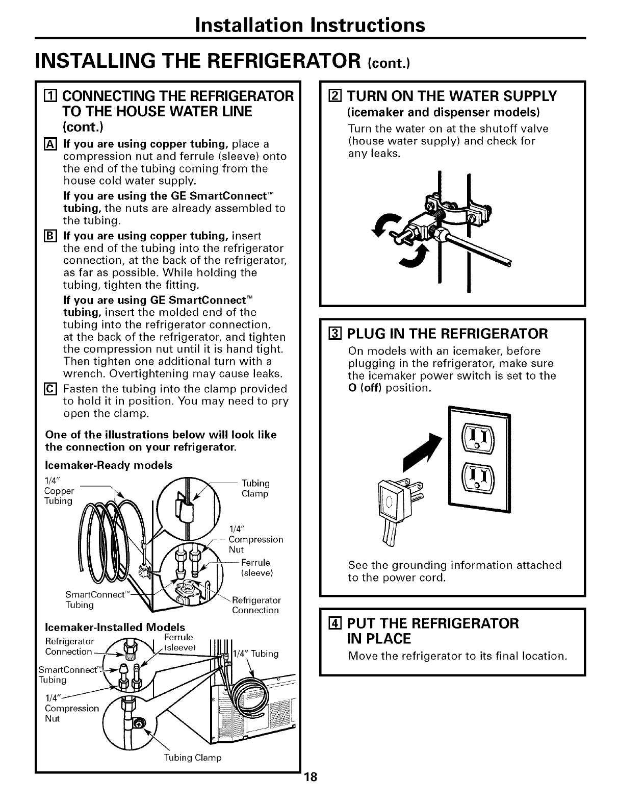
[] CONNECTING THE REFRIGERATOR
TO THE HOUSE WATER LINE
(icemaker and dispenser models)
A cold water supply is required for automatic
icemaker operation. If there is not a cold water
supply, you will need to provide one. See
Installing the Water Line section.
NOTES:
• Before making the connection to the
refrigerator, be sure the refrigerator power cord
is not plugged into the wall outlet.
• If your refrigerator does not have a water filter,
we recommend installing one if your water
supply has sand or particles that could clog the
screen of the refrigerator's water valve. Install it
in the water line near the refrigerator. If using
GE SmartConnect TM Refrigerator Tubing Kit, you
will need an additional tube (WXO8XIO002) to
connect the filter. Do not cut plastic tube to
install filter.
17
Installation Instructions
INSTALLING THE REFRIGERATOR (cont,)
[] CONNECTING THE REFRIGERATOR
TO THE HOUSE WATER LINE
(cont.)
[] If you are using copper tubing, place a
compression nut and ferrule (sleeve) onto
the end of the tubing coming from the
house cold water supply.
If you are using the GE SmartConnect TM
tubing, the nuts are already assembled to
the tubing.
[] If you are using copper tubing, insert
the end of the tubing into the refrigerator
connection, at the back of the refrigerator,
as far as possible. While holding the
tubing, tighten the fitting.
If you are using GE SmartConnect TM
tubing, insert the molded end of the
tubing into the refrigerator connection,
at the back of the refrigerator, and tighten
the compression nut until it is hand tight.
Then tighten one additional turn with a
wrench. Overtightening may cause leaks.
[] Fasten the tubing into the clamp provided
to hold it in position. You may need to pry
open the clamp.
One of the illustrations below will look like
the connection on your refrigerator.
Icemaker-Ready models
1/4" -- Tubing
Copper Clamp
Tubing
1/4"
Compression
Nut
(sleeve)
SmartConnect T"
Tubing gerator
Connection
Icemaker-lnstalled Models
Refrigerator Ferrule
Connection 1/4" Tubing
[] TURN ON THE WATER SUPPLY
(icemaker and dispenser models)
Turn the water on at the shutoff valve
(house water supply) and check for
any leaks.
[] PLUG IN THE REFRIGERATOR
On models with an icemaker, before
plugging in the refrigerator, make sure
the icemaker power switch is set to the
O (off) position.
%
%
See the grounding information attached
to the power cord.
[] PUT THE REFRIGERATOR
IN PLACE
Move the refrigerator to its final location.
18

Installation Instructions
[] REMOVE THE FRESH FOOD
DOOR HANDLE
(For placement in the installation
location or reversal of the handles -
on some models)
Stainless steel (on some models):
O REMOVING
THE DOOR
HANDLE: Loosen
the set screws
with the 3/32"
Allen wrench
and remove
the handle.
OREVERSING THE
DOOR HANDLE:
• Remove the
handle mounting
fasteners with a
1/4" Allen
wrench and
transfer the
O_adge
lug
utton
J
.Mounting
Fasteners
(appearance may vary)
handle mounting fasteners to the right side.
* Remove and transfer the plug button and
logo badge to the left side of the fresh food
door. NOTE: Use a flat plastic edge to prevent
damaging the door. Remove any adhesive on
the door with a mild detergent. Remove the
paper covering on the adhesive backing on
the logo badge prior to carefully attaching the
badge to the door.
Plastic handle (on some models):
REMOVING
THE DOOR
HANDLE: Slide
the handle up
on the handle
mounting
fasteners and
remove the
handle.
OREVERSING THE
DOOR HANDLE:
.Remove the
handle Button
mounting Mounting Fasteners
fasteners with a
3/8" or 10 mm (appearance may vary)
socket wrench and transfer the handle
mounting fasteners to the right side.
.Remove and transfer the plug button and
logo badge to the left side of the fresh food
door. NOTE: Use a flat plastic edge to prevent
damaging the door. Remove any adhesive on
the door with a mild detergent. Remove the
paper covering on the adhesive backing on
the logo badge prior to carefully attaching the
badge to the door.
After removing the handle: Move the small plug
button from the top right side of the door top and
insert it into the hole on the opposite side.
(appearance may vary)
[] REMOVE THE FREEZER DOOR
HANDLE
Stainless steel handle:
O Loosen the set screws located on the underside
of the handle with the 3/32" Allen wrench and
remove the handle.
NOTE: If the handle mounting fasteners need to
be tightened or removed use a 1/4" Allen wrench.
Plastic handle:
Q Slide the handle to the right on the handle
mounting fasteners and remove the handle.
NOTE: If the handle mounting fasteners need to
be tightened or removed use a 3/8" or 10 mm
socket wrench.
Mounting
fasteners
(appearance may vary) Slots on back
of handle
19

Installation Instructions
INSTALLING THE REFRIGERATOR (cont.)
[] ATTACH THE FRESH FOOD
DOOR HANDLE
Stainless steel handle:
Attach the handle
to the handle
mounting
fasteners and
tighten the set
screws with a
3/32" Allen
wrench. Mounting
Fasteners
Plug
(appearance may vary)
Plastic handle:
O Attach the handle to the handle mounting
fasteners by aligning the slots with the handle
mounting fasteners.
0Slide it down until it is firmly locked into
position.
Mounting
fasteners Slots on back of
handle
(appearance may vary)
[] ATTACH THE FREEZER DOOR
HANDLE
Stainless steel handle:
Q Attach the handle to the mounting fasteners
and tighten the set screws on the bottom of
the handle with a 3/32" Allen wrench.
(appearance may vary)
Plastic handle:
Q Attach the handle to the mounting fasteners by
aligning the slots with the mounting fasteners.
OSlide it to the left until it is firmly locked into
position.
NOTE: A properly locked handle will be centered
on the freezer.
Mounting
fasteners
Slots on back
(appearance may vary) of handle
20

Installation Instructions
[] LEVEL THE REFRIGERATOR
The leveling legs have 3 purposes:
1) Leveling legs adjust so the door closes
easily when opened about halfway.
(Front of the refrigerator should be
1/4" [6 mm] higher than the rear of
the refrigerator).
2) Leveling legs adjust so the refrigerator
is firmly positioned on the floor and
does not wobble.
3) Leveling legs serve as a stabilizing
brake to hold the refrigerator securely
in position during operation and
cleaning.
[] Turn the leveling legs clockwise to raise the
refrigerator, counterclockwise to lower it.
CAUTION: Toavoidpossible
personal injury or property damage, the
leveling feet must be firmly touching
the floor.
[] Install the base grille by aligning the
prongs on the back of the grille with the
holes in the cabinet. Push forward until
the grille snaps into place.
[] SET THE CONTROLS
Set the controls to the recommended
setting.
5 5
[.EOOMME.OEOCO.T.OLSETT..OS]
0"F IS RECOMMENDED 37 =F IS RECOMMENDED
[] REMOVE PACKAGING
START ICEMAKER
(icemaker models)
A) Remove all tape, foam and protective
packing from shelves and drawers.
B) Remove the tie downs from the freezer
baskets.
C) Place half width basket onto drawer
slides. See About the freezer section
for instructions.
Set the icemaker power switch to the
I (on) position. The icemaker will not
begin to operate until it reaches its
operating temperature of 15°F (-9°C)
or below. It will then begin operation
automatically. It will take 2-3 days to
fill the ice bin.
Pow
switch - I
NOTE:
In lower water pressure conditions, the
water valve may turn on up to 3 times
to deliver enough water to the icemaker.
21
Installation Instructions
REMOVING THE FREEZER DRAWER (on some models)
The freezer drawer can be removed, if needed,
to fit through tight areas.
Read these instructions completely and carefully.
[] REMOVE THE BASKET
[] Open the freezer drawer until it stops.
[] The freezer basket rests on a frame inside
the freezer drawer. Lift the basket up at
the back.
[] Lift the front up and lift the entire basket
up and out of the drawer.
\
[] REMOVE THE DRAWER FRONT
FROM THE SLIDES
[] Remove the Phillips head screw on each
side of the railing.
(_ DO NOT remove the hex head
screws from the rail assemblies.
DO NOT remove
hex head screws
DO NOT remove
hex head screws
[] REMOVE THE DRAWER FRONT
FROM THE SLIDES (cont.)
[] Lift up on both sides of the freezer drawer
handle to separate the drawer railings
from the rail assemblies.
[] Set the drawer front on a non-
scratching surface.
[] Push the rail assemblies back into
locking position.
Rail
Assembly Drawer
Assembly
[] REMOVE THE LEVELING LEGS
(if needed)
If, after removing the freezer drawer and
refrigerator door, the refrigerator will still
not fit through a doorway, the leveling leg
brackets can be removed.
[] Remove the base grille by grasping it at
the bottom and pulling it straight out.
[] Remove both brackets with a 3/8" hex
head driver.
22

Installation Instructions
REPLACING THE FREEZER DRAWER (on some models)
I(_Two people may be required to complete
this procedure.
[] ATTACH AND SECURE THE
DRAWER FRONT TO THE SLIDES
[] Pull out the rail assemblies to the full
length on each side of the cabinet.
[] Locate the slots on the inside of the rail
assemblies near the back.
Slot
[]
[]
G
Rail assembly
Insert the hooks at the back of the
drawer railings into the slots on the rail
assemblies.
Lower the front of the drawer, making
sure the tabs on the sides of the railings
fit into the front slots in the rail assemblies,
II
• "j_ '
I[] ATTACH AND SECURE THE
DRAWER FRONT TO THE SLIDES
(cont.)
[] Replace the Phillips head screws on both
rail assemblies.
Phillips
Screw
[] REPLACE THE FREEZER BASKET
Replace the lower freezer basket by
lowering it into the frame.
23

Installation Instructions
REVERSING THE DOOR SWING
IMPORTANT NOTES
When reversing the door swing:
NOTE: Door swing is not reversible on some
stainless steel models.
•Read the instructions all the way through
before starting.
• Handle parts carefully to avoid scratching
paint.
• Set screws down by their related parts to
avoid using them in the wrong places.
•Provide a non-scratching work surface for
the doors,
IMPORTANT: Once you begin, do not move
the cabinet until door-swing reversal is
completed.
These instructions are for changing the
hinges from the right side to the left side--if
you ever want to change the hinges back to
the right side, follow these same instructions
and reverse all references to left and right.
• Once door swing is finalized, ensure
the logo badge is properly aligned and
permanently secured to the door by
removing the adhesive cover on the back
side. NOTE: If necessary call Customer
Service for a replacement badge.
Unplug the refrigerator from its electrical
outlet,
Empty all door shelves, including the dairy
compartment.
TOOLS YOU WILL NEED
Adjustable Wrench
3/8"and 10 mm Socket
Drivers
Masking Tape Putty Knife or
Thin-blade Screwdriver
Phillips Screwdriver
24
[] REMOVE THE
REFRIGERATOR DOOR
[] Tape the door shut with masking tape.
[]
[]
[]
Remove the hinge cover on top of the
refrigerator door by squeezing it and
pulling it up.
Using a 3/8" or 10 mm socket driver,
remove the bolts securing the top hinge to
the cabinet. Then lift the hinge straight up
to free the hinge pin from the socket in the
top of the door.
__ Hing_e COver
e
Remove the tape and tilt the door away
from the cabinet. Lift the door off the
center hinge pin.
[] Set the door on a non-scratching surface
with the inside up.

Installation Instructions
[] REMOVE THE CENTER HINGE PIN
[] On models with a freezer door, tape the
door shut with masking tape.
[] Using an adjustable wrench, remove the
center hinge pin.
[] REMOVE THE FREEZER DOOR
(freezer door models)
[] Remove the tape and tilt the door away
from the cabinet. Lift the door off the
bottom hinge pin.
NOTE: There is a plastic washer between
the hinge and the top of the freezer door.
Do not lose.
[] Set the door on a non-scratching surface
with the inside up.
[] REMOVE CENTER HINGE
Using a 3/8" or 10 mm socket driver and
Phillips head screwdriver, remove the
bolts and screws securing the center
hinge to the cabinet. Set hinge, bolts,
screws, washer (on freezer door models)
and hinge pin aside.
On models with a freezer drawer, skip to
Step 7.
[] TRANSFER BOTTOM HINGE
BRACKET (freezer door models)
[] Remove the base grille by grasping it at
the bottom and pulling it straight out.
\
[] Using a 3/8" or 10 mm socket driver,
remove the screws securing the bottom
hinge bracket to the cabinet.
[] Using an adjustable wrench, remove the
hinge pin and washer(s) from the right
side of the bracket and install on the left.
[] Using a 3/8" or 10 mm socket driver,
remove the leveling leg bracket from the
bottom left side of the cabinet and install
it on the right side.
Left Side Right Side
25

Installation Instructions
REVERSING THE DOOR SWING (cont.)
[] TRANSFER BOTTOM HINGE
BRACKET (freezer door models, cont.)
[] Install the bottom hinge bracket on the
left side of the cabinet.
[] Replace the base grille by aligning the
prongs on the back of the grille with the
holes in the cabinet, Push forward until
the grille snaps into place,
[]
[]
[]
[]
TRANSFER FREEZER DOOR STOP
(freezer door models)
Remove the door stop on right side of the
bottom of the freezer door by removing
the two screws.
Move the plastic hinge hole thimble to the
opposite hole.
Install the door stop on the left side.
Bottom of Freezer Door
(Right Side)
Bottom of Freezer Door
(Left Side)
[] INSTALL CENTER HINGE
[] Transfer the plug button and screws in
the hinge holes on the left side to the
right side.
[] Install the center hinge on the left side.
S!!!
[] HANG THE FREEZER DOOR
(freezer door models)
Lower the freezer door onto the bottom
hinge pin, then shut the door, making
sure to align the door with the cabinet.
Make sure the gasket on the door is flush
against the cabinet.
26

Installation Instructions
[] INSTALL CENTER HINGE PIN
[] Install the center hinge pin.
NOTE: On models with a freezer door,
be sure to put the washer between the
top of the freezer door and the bottom
of the center hinge.
Freezer Door Models Freezer Drawer Models
[] TRANSFER REFRIGERATOR
DOOR STOP
[] Remove the door stop on right side of
the bottom of the refrigerator door by
removing the two screws.
[] Move the plastic hinge hole thimble to
the opposite hole.
[] Install the door stop on the left side,
making sure to line up the screw holes
in the door stop with the holes in the
bottom of the door,
Bottom of Bottom of
Refrigerator Door Refrigerator Door
(Right Side) (Left Side)
I_] REHANG REFRIGERATOR DOOR
[] Lower the refrigerator door onto the
center hinge pin.
[]
[]
Insert the top hinge pin into the hinge
hole on top of the refrigerator door. Make
sure the door is aligned with the cabinet.
Attach the hinge to the top of the cabinet
loosely with the bolts.
Make sure the gasket on the door is
flush against the cabinet and is not
folded. Support the door on the handle
side and make sure the door is straight
and the gap between the doors is even
across the front. While holding the door
in place, tighten the top hinge screws.
Replace the hinge cover.
[_ TRANSFER REFRIGERATOR
DOOR HANDLE TO RIGHT
Refer to Remove the Fresh Food Door
Handle and Attach the Fresh Food Door
Handle sections for instructions,
27

Installation Instructions
INSTALLING THE WATER LINE (ICEMAKER MODELS)
BEFORE YOU BEGIN
Recommended copper water supply kits are
WX8X2, WX8X3 or WX8X4, depending on the
amount of tubing you need. Approved plastic
water supply lines are GE SmartConnect TM
Refrigerator Tubing (WX08X10002,
WX08X10006, WX08X10015 and
WX08X 10025).
When connecting your refrigerator to a GE
Reverse Osmosis Water System, the only
approved installation is with a GE RVKit. For
other reverse osmosis water systems, follow
the manufacturer's recommendations.
If the water supply to the refrigerator is from
a Reverse Osmosis Water Filtration System
AND the refrigerator also has a water filter,
use the refrigerator's filter bypass plug. Using
the refrigerator's water filtration cartridge in
conjunction with the RO filter can result in
hollow ice cubes.
This water line installation is not warranted
by the refrigerator or icemaker manufacturer.
Follow these instructions carefully to
minimize the risk of expensive water damage.
Water hammer (water banging in the pipes)
in house plumbing can cause damage to
refrigerator parts and lead to water leakage
or flooding. Call a qualified plumber to correct
water hammer before installing the water
supply line to the refrigerator.
To prevent burns and product damage, do not
hook up the water line to the hot water line.
If you use your refrigerator before connecting
the water line, make sure the icemaker power
switch is in the O (off) position.
Do not install the icemaker tubing in areas
where temperatures fall below freezing.
When using any electrical device (such as a
power drill) during installation, be sure the
device is double insulated or grounded in a
manner to prevent the hazard of electric
shock, or is battery powered.
All installations must be in accordance with
local plumbing code requirements.
WHAT YOU WILL NEED
J
•Copper or GE SmartConnect TM Refrigerator
Tubing kit, 1/4" outer diameter to connect
the refrigerator to the water supply. If using
copper, be sure both ends of the tubing are
cut square.
To determine how much tubing you need:
measure the distance from the water valve
on the back of the refrigerator to the water
supply pipe. Then add 8' (2.4 m). Be sure
there is sufficient extra tubing (about 8' [2.4 m]
coiled into 3 turns of about 10" [25 cm]
diameter) to allow the refrigerator to move
out from the wall after installation.
GE SmartConnect TMRefrigerator Tubing Kits
are available in the following lengths:
2' (0.6 m) - WXO8XIO002
6' (1.8 m) -WXO8XIO006
15' (4.6 m) - WXO8X10015
25' (7.6 m) - WXO8X10025
Be sure that the kit you select allows at least
8' (2.4 m) as described above.
28

Installation Instructions
WHAT YOU WILL NEED (CONT.)
NOTE: The only GE approved plastic tubing
is that supplied in GE SmartConnect TM
Refrigerator Tubing kits. Do not use any
other plastic water supply line because the
line is under pressure at all times. Certain
types of plastic will crack or rupture with age
and cause water damage to your home.
•AGE water supply kit (containing tubing,
shutoff valve and fittings listed below) is
available at extra cost from your dealer or
from Parts and Accessories, 800.626.2002
(in Canada 1.888.261.3055),
•Acold water supply. The water pressure must
be between 20 and 120 p,s.i. (1.4-8.1 bar).
•Power drill.
•1/2" or adjustable wrench.
• Straight and Phillips blade screwdriver.
•Two 1/4" outer diameter compression nuts
and 2 ferrules (sleeves)--to connect the
copper tubing to the shutoff valve and the
refrigerator water valve.
OR
• If you are using a GE SmartConnect TM
Refrigerator Tubing kit, the necessary
fittings are preassembled to the tubing,
• If your existing copper water line has a
flared fitting at the end, you will need an
adapter (available at plumbing supply
stores) to connect the water line to the
refrigerator OR you can cut off the flared
fitting with a tube cutter and then use a
compression fitting. Do not cut formed end
from GE SmartConnect TMRefrigerator tubing.
• Shutoff valve to connect to the cold water
line. The shutoff valve should have a water
inlet with a minimum inside diameter of
5/32" at the point of connection to the COLD
WATER UNE. Saddle-type shutoff valves are
included in many water supply kits. Before
purchasing, make sure a saddle-type valve
complies with your local plumbing codes.
Install the shutoff valve on the nearest
frequently used drinking water line.
[] SHUT OFF THE MAIN WATER
SUPPLY
Turn on the nearest faucet long enough
to clear the line of water.
[] CHOOSE THE VALVE LOCATION
Choose a location for the valve that is
easily accessible. It is best to connect into
the side of a vertical water pipe. When it is
necessary to connect into a horizontal
water pipe, make the connection to the
top or side, rather than at the bottom,
to avoid drawing off any sediment from
the water pipe.
[] DRILL THE HOLE FOR THE VALVE
Drill a1/4" hole in the water pipe (even if
using a self-piercing valve), using a sharp
bit. Remove any burrs resulting from
drilling the hole in the pipe,
Take care not to allow water to drain into
the drill.
Failure to drill a 1/4" hole may result in
reduced ice production or smaller cubes.
29

Installation Instructions
INSTALLING THE WATER LINE (CONT.)
[] FASTEN THE SHUTOFF VALVE
Fasten the shutoff valve to the cold water
pipe with the pipe clamp.
Pipe
Saddle-Type
Shutoff Valve
Cold Water Pipe
NOTE: Commonwealth of Massachusetts
Plumbing Codes 248CMR shall be adhered
to. Saddle valves are illegal and use is not
permitted in Massachusetts. Consult with
your licensed plumber,
[] TIGHTEN THE PIPE CLAMP
Tighten the clamp screws until the sealing
washer begins to swell.
NOTE: Do not overtighten or you may
crush the tubing.
Pi
Washer
Inlet End
Clamp
Screw
[] ROUTE THE TUBING
Route the tubing between the cold water
line and the refrigerator.
Route the tubing through a hole drilled in
the wall or floor (behind the refrigerator or
adjacent base cabinet) as close to the wall
as possible.
NOTE: Be sure there is sufficient extra
tubing (about 8' [2.4 m] coiled into 3 turns
of about 10" [25 cm] diameter) to allow the
refrigerator to move out from the wall after
installation.
[] CONNECT THE TUBING
TO THE VALVE
Place the compression nut and ferrule
(sleeve) for copper tubing onto the end
of the tubing and connect it to the
shutoff valve,
Make sure the tubing is fully inserted
into the valve, Tighten the compression
nut securely.
For plastic tubing from a GE
SmartConnect TM Refrigerator Tubing kit,
insert the molded end of the tubing into
the shutoff valve and tighten compression
nut until it is hand tight, then tighten one
additional turn with a wrench.
Overtightening may cause leaks.
Saddle-Type
Sh utoff Va Ive
j.
Packing Nut
Outlet Valve
Compression Nut
/SmartConnect TM
/Tubing
Ferrule (sleeve)
NOTE: Commonwealth of Massachusetts
Plumbing Codes 248CMR shall be adhered
to. Saddle valves are illegal and use is not
permitted in Massachusetts. Consult with
your licensed plumber.
[] FLUSH OUT THE TUBING
Turn the main water supply on and flush
out the tubing until the water is clear,
Shut the water off at the water valve after
about one quart (1 liter) of water has been
flushed through the tubing.
I To complete the installation of the refrigerator, I
go back to Step 1 in Installing the Refrigerator.
30

Normal operatingsounds, vvvvw.GEAppliances.com
Newer refrigerators sound different from older refrigerators.
Modem refrigerators have more features and use newer technology.
Do you hear what I hear? These sounds are normal
HUMMM...
--WHOOSH...
Tile new high eflicienQ compressor ma) run fkJsterand longer
than your old refl'igerator and ?xm m_} hear a high-pitched
hum or pulsating sound _hile it is open_ting.
NY)u may Ileal" a whooshing sound when tile doors close. This is
due to pl_ssure equalizing within the reii-lgeratol:
CLICKS, POPS,
CRACKS and SNAPS
Ym may Ileal" cracking or popping sounds when tile
reii-lgerator is iilst plugged ill. This happens as the reii-lgemtor
cools to the correct temperature.
@ The ti'eezer control will click when starting or stopping the
compressol:
Defl'ost diner snapping ill and out of tile defi'ost c\cle.
N Expansion and contraction of cooling coils (huing and atter
defl'ost can cruise a cracking or popping sound.
@ On models with all icemake/, after all icemaking cycle, you
may hear the ice cubes dropping into the ice bucket.
@ On models with a dispenser, during wamr dispense, gm
may hear the water lines move at initial dispense and after
dispenser button is released.
WHIR./
Ym mm hear fl_e iims spinning at high speeds. This happens
\d/en tile l_fl'igerator is first plugged ill, \d/en tile dools are
opened ti'equemly or \_hen a lane ml/ount of food is added to
the refl'igerator or ti'eezer conq)armlents. Tile rims are helping
to mNntain file correct temperatures.
@ Tile tims change speeds ill order to provide optimal cooling
and energ) smings.
WATERSOUNDS
6
The flow of refl'igerant flmmgh the ti'eezer cooling coils n/ay
make a gurgling noise like boiling wawr
Water dropping on the deii'ost heater call cause a sizzJing,
popping or buzvJng sound during tile defi'ost Qcle.
, A _lmr dripping noise ma} occur during the defl'ost cycle as
ice melts ti'om tile ev_q)onm)r and flows into the dndn pan.
@ Closing tile door may cause a gurgling sound (hie to pressure
equalization.
Before you call for service...
Troubleshooting -tips
Save time and money! Review the charts on the following
pages first and you may not need to call for service.
Refrigerator does not
operate
Vibration or rattling
(slight vibration
is normaO
Possible Causes
Refrigerator in defrost cycle.
What To Do
•_'_fit about 30 inilmtes fin" detrost cycle to end.
Control in 0 (off)position. • Miwe tile control to a telnperamre setting.
Refrigerator is unplugged. • Push the plug completely into the outlet.
The fuse is blown/circuit • Replace fllse or reset the breaker.
breaker is tripped.
Leveling legs need adjusting. •See Level the Refrigeratoc
31

Before you call forservice...
Troubleshooting -tips
Possible Causes What ToDo
•_.fit 94 houI_ tor the refi_igerator to completely
COOl dowu.
• This is noimal.
Motor operates for Normal when refrigerator
long periods or cycles is f'mst plugged in.
on andofffrequently. Often occurs when large
(Modern refrigerators mnom_ts of food are
with more storage
space and a larger placed in refrigerator.
freezerrequiremore Door left open. •Check to see if package is holding door o )ell
, , } •
operating time. They
start and stop often Hot weather or frequent • This is n(mnal.
to maintain even door opelfings.
Temperature control • See About the controls.
set at the coldest setting.
Grille mad condenser need • See Care and cleaning.
clemlh_g.
TurboCool function has been • This is n()imal when the Turbo(_ool timcfion is activated.
activated. See About TurboCoolf()r m()re infi)mmti(m.
Refrigerator or freezer Temperature controls not set •See About the controls.
compartmenttoowarm cold enough.
Warm weather or frequent • Set the teIuperature coutrol oue step coldel:
door opelfings. See About the controls.
Door left open. • Check to see if package, is holding, door el)ell.
Frostorice crystals Door left open. • Check to see if package is holding door open.
onfrozenfood
(frost within package Too frequent or too long
is normal) door openhlgs.
Frequent"buzzing" lcema_ker power switch is in •Set the power switch to the 0 (off) position. Keeping it
sound the I (on) position, but the ill tile I (on) l/()sition will damage the water valve.
water supply to the refrigerator
has not been com_ected.
Smallorhollow cubes Water Filter clogged. •Replace filter cartridge with new cartridge, or with l)lug,.
Automaticicemaker lcema_ker power switch is •Set the power switch to the I(on)position.
(on some models) not on. The icemaker power light will turn green when the
does not work fi'eezer light switch is pressed ill or when the fl'eezer
door is closed.
Water supply turned off or • See Installingthe waterline.
not comzected.
Freezer compartment •_4'ait 24 hotu_ fi)r the refrigerator to completely
to0 _varl_. c( )( )1 d( )\VU,
Piled up cubes in the storage • l,evel cubes by haud.
bin cause the icemaker
to shut off.
Ice cubes stuck in icemaker. • Turn off tile icemakel; remove cubes :rod turn the
(Green power fight on icemaker back on.
icemaker blh_h_g.)
lcema_ker fight is not fit. • This is hernial when tile freezer door is open. The
loci/laker [lower light, will turu ,gl'eeu wheu tile fl'eezer
light switch is pressed ill or wheu the fi'eezer door is
ch)sed.

www.GEAppliances.com
Possible Causes What To Do
Ice cubes have Food lrmlsmitthlg odor/taste * _'ra 1)tb()(ls well.
odor/taste to ice cubes.
Interior of refrigerator *See Care and cleaning.
needs clemfilzg.
Slowice cube freezing Door left open. *Check to see if l)ackage is hol(liug door ol)eu.
Freezer cona-ol not set *See About the controls.
cold enough.
Refrigerator has odor Foods trm_smitth_g * Foods with strong 1)(11)_ should be tightly Wral)ped.
odor to refrigerator. * Kee l) au i)peu box of bakiug soda iu the refi_igerator;
rel)lace every three mouths.
Interior needs cleaning. * See Care and cleaning.
Moisture forms on Not unusual during * _'il)e surtilce 11i3' and reset die i'ei_Jgerator ( ontrol
outside of refrigerator periods of high humidity. /)ue .settiu,_ colder:
Moisture collects inside Too frequent or too
(in humid weather, air long door openings.
carries moisture into
refrigerator when doors
are opened)
Refrigerator or freezer No power at outlet. * Replace fuse or reset the l)reakel:
compartment light does Light bulb burned out or loose. *See Replacing the light bulbs
not work
Door/drawer does not Levelh_g legs need adj usth_g. *See Installingthe Refrigerator
close by itself
Freezer door/drawer This is normal if, after popping * This iudi(ates that there is a good seal I)U the fl'eezer
pops open when open, the freezer door/drawer door/drawe_:/f the fl'eezer door/drawer does u()t
refrigerator door closed on its own. automaficalh" close :liter popl)iug opeu, then see the
is closed Problem: Door/drawer does not close by itself, ab(we.
Hotak frombottom
of refrigerator
Nonnad air flow cooling
motor. In the refrigeration
process, it is normal that
heat be expelled in the
area under the refrigerator.
Some floor coverings will
discolor at these normal
and safe temperatures.
Food freezing in Food too close to the air vent * Move the fi)od away from the air veut (he;it the
the refrigerator at the back of the refrigerator, coutr()ls).
Refrigerator control is set *M()ve the reflJger;it()r c()ntr()l t() ;i \v_llluer
too cold. [elUl)el';itt/l'e settiug, ()lie iucl'euleut _lt ;i time.
Orange glow Defrost heater is on. * This is uom_al.
in the freezer
33

Before you call forservice...
Troubleshooting -tips
Possible Causes What ToDo
Water has poor Water dispenser has not been *Dispense water tmtil :ill water in system is
taste/odor used for a long time. replenished.
Waterin fimtglass Normal when refrigerator *_4ait 24 hotn_ tbr the reiiigerator to completely
is warm is In'st installed, co_l down.
Water dispenser has not been • Dispense water tmfil :ill water is system is
used for a long time. replenished.
Water system has been drained. *_Mlow several horus for replenished stq)plv to chill.
Water dispenser Water suppby line turned off *See Installing the water line.
does not work or not cmmected.
Water filter dogged. *Replace filter cartridge or rem_we filter aml iust_dl l)lug.
Air may be trapped in *Press the dispenser a_m for at least 2 miuutes.
the water system.
Water spurting from Ne_dy-hastaUed filter cartridge. *Rttu water fi'om the disl)euser for 3 mim/tes
dispenser (about 1½ gallons).
Wateris not dispensed Water ha reservoir is frozen *Set the refi_igerator control to a w;ivIl/el" settiug and
buticemaker is working because the controls are wait 24 horus./f water does not dispeuse after 24 horus,
set too cold. call tbr service.
No waterorice cube Supply line or shutoff valve *(',:illa l)ltunbe_:
production is dogged.
Water filter dogged. *Replace filter cartridge or remove filter aml iust_dl l)lug.
Filter cm'tridge not *RelHove aud reiust_dl filter cartridge, beiug cert_lin that
properly hastalled, it locks into place. The blade on the end of the cartridge
shotdd be positioned verticall):
Water is leaking from Glass not being held under *Hold the glass Imderueath the disl)euser fin" 2-3 secouds
dispenser the dispenser long enough alter releasing the dispenser button. _.Liter may continue
after button is released, to disl)euse after the butt_m is released.
• Disl)euse water tor at le;ist 2 l/liut/tes to l'el/lOVe ;Ill"
t]'oln svstelII,
Air may be present ha the
water line system, caushag
water to drip after being
dispensed.
34

www.GEAppliances.com
Possible Causes What To Do
My displayis showing kc TurboCool function is activated. • See About TurboCool fi)r l//Ol'e int()vlnntion.
Waterfilterindicatorlight This is normal • See About the waterfilterlbr more infOm_afion.
Waterfilter indicator light Water filter indicator must • Press and hold tire RESET WATERFILTERpad fi)r 3
remains red even after be reset, seconds. See About the water filter tbr more infom_ation.
replacing the water filter
Waterfilterindicator This is normal. This fight will •See Aboutthewaterfilterlormore infbm/ation.
light is not lit tuna orange to tell you that you
need to replace the f'dter soon.
The f'flter cartridge should be
replaced when the replacement
indicator light tunas red.
Handle is loose/handle Hmzdle needs adjusting. •See Attach the Fresh Food handle and Attach the
has a gap Freezer handle sections fi)r detMled instrt/ctions.
Refrigerator beeping This is the door alarm. • (_]ose (h)o_:
Controlsetting is notlit On some models, the fight • If tire control settings do not light up, check to see if tire
bulbs at the top of the refrigerator light btdbs are btwned out, and replace if necessa_3".
compartment fight up the
temperature control settings.
35

m
_ Notes_
lmi
m
m
lmi
m
i
_J
m
m
m
immmb
i_qu_
--R
q_b
m
Q_
€_
3C

GE Service Protection Plus 'M
GE, a name recognized worldwide for quality and dependability, oflers you
Service Protection Plus "--comprehensive protection on all your appliances--
No Matter What Brand!
Benefits Include:
• Backed by GE
•All brands covered
• Unlimited service calls
• All parts and labor costs included
• No out-of-pocket expenses
•No bidden deductibles
•One 800 number to call
We71 CoverAny Appliance.
Anywhere. Anytime.*
You will be completely satisfied with our service protection or )ou Ina) request )our ilaone_ back
on the remaining value of your contract. No questions asked. It's that simple.
Protect your refl'igeratoi; dishwashei; washer and dlyei; range, TV, V(:R and inuch more--aaay brand!
Plus there's no extra charge fi)r eu_ergency ser;'ice and low monthly fii_ai_cing is awfilable. Even icemaker
coverage and tood spoilage protection is offered. You can rest easy; knowing that all vour wduable
household products are protected against expensive repairs.
Place your confidence in GE and call us in the U.S. toll-free at _OU.l)Zl).ZZZ_
for UlOi'e ilatorlnatiola.
'All bl_mds cmered, up m 20 )<;us _ld. in the _mtin< ntal [.S.
._Cut here
Please place in envelope and mail to:
GeneralElectricCompany
Warranty Registration Department
P.O. Box 32150
Louisville, KY40232-2150
37

Consumer Product Ownership Registration
Dear Customer:
Thank you for purchasing our product and thank you for placing your confidence in us.
_A/eare proud to ha_e you as a customer!
Follow these three steps to protect your new appliance investment:
Complete mid mail
your Consumer
Product Owuership
Registration today.
t]a_e the t)eace o/
mind of knowing we
c_ln contact you ill
th( unlikely (v(nt of
a sa/_q_ modification.
AJler mailing tile
registration below,
store this do( ument
in a sale' place. It
contains intormation
you will need should
you require service.
Our service nmnber is
800 GE CARES
(800.432.2737).
[_{'a(t VO/IF Owl/er's
Mamml carefully.
It will help you
operam your new
appliance properly.
Model Number Serial Number
I I
Important: If you did not get a registration card with your
product, detach and return the form below to
ensure that your product is registered, or register
online at www.GEAppliances.com.
Consumer Product Ownership Registration
,_,,,,_ Cm h<r_
Model Number Serial Number
I I I
MI: Ms. M*_. Mixs
Fir_,l I ILasl]
Name IIIIIIIII Nanl(! I I I I I I I I I I I I
_1 r( (!1 I
Add r,. ';s IIIIIIIIIIIIIIIIII IIIIII
,I
I
I
Apt. 4#Ii i
(;i,vI I I
l )aw Placed
hi Use ]1]
Monlh
I I I I I IEqnailAddress*
I I I I I I I I s_., I
_:!a r III Phon(
Nunll)(!r I,I
Zip I
I ] Code I I II
I-I,, I-I , , ,
I
I
GEAppliances
BE Consumer&/ndnstrial
lonisvi//e, Kentucky
ww_GE@pliances, com
* Please provide your eqnail address to receive, via eqnail, discounts, special ottLp, and other iml)ortant
communications frOlll GE Appliances (GEA).
Check here if you do not want to receive communications ti-om GEA's caretully selected partners.
FAII.I RE T() C()MPI.ETE AND RE'F[ RN Tt tIS CARD DOES NOT DIMINISII Y( )l R
BL\RRANTY RI (;I ITS.
For intormation about GEA's prixacy and data usage polic); go to >nvw.Gl_Appliances.com and click
on 'Prixacy Policy" or call 800.626.2224.
38

CUSTOMER WARRANTY
(for customers in Canada)
Your refrigerator is warranted to be free of defects in material and workmanship.
What is covered
Sompressor
Sealed System (including
avaporator, condenser
Lubing and refrigerant)
How Long Warranted
(From Date of Sale)
Five (5) Years
Five (5) Years
Parts
Repair or Replace
at Camco's Option
Five (5) Years
Five (5) Years
Labour
Five (5) Years
Five (5) Years
&ll Other Parts One (1) Year One (1) Year One (1) Year
TERMS AND CONDITIONS:
1. This warranty applies only for single
family domestic use in Canada when the
Refrigerator has been properly installed
according to the instructions supplied by
Camco and is connected to an adequate
and proper utility service.
Damage due to abuse, accident,
commercial use, and alteration or
defacing of the serial plate cancels all
obligations of this warranty.
Service during this warranty period must
be performed by an Authorized Camco
Service Agent.
2. Neither Camco nor the Dealer is liable for
any claims or damages resulting from
failure of the Refrigerator or from service
delays beyond their reasonable control.
3. To obtain warranty service, purchaser
must present the original Bill of Sale.
Components repaired or replaced are
warranted through the remainder of the
original warranty period only.
4. This warranty is in addition to any
statutory warranty.
WHAT IS NOT COVERED:
• Owner is responsible to pay for sewice
calls related to product installation and/or
teaching how to use the product.
• Damage to finish must be reported
within 48 hours following the delivery of
the appliance.
• Improper installation--proper installation
includes adequate air circulation to the
refrigeration system, adequate electrical,
plumbing and other connecting facilities.
• Replacement of house fuses or resetting
of circuit breakers.
• Replacement of light bulbs.
• Damage to product caused by accident,
fire, floods or acts of God.
• Loss of food due to spoilage.
• Proper use and care of product as listed
in the owner's manual, proper setting of
controls.
• WARRANTOR IS NOT RESPONSIBLE
FOR CONSEQUENTIAL DAMAGES.
IMPORTANT
Keep this warranty and your bill of sale as proof of original purchase and purchase date.
Camco Service is available coast to coast.
If further help is needed concerning this
warranty, contact:
Manager, Consumer Relations
Camco Inc., Consumer Service
1 Factory Lane
Suite 310
Moncton, New Brunswick ElC 9M3
Staple your receipt here.
Proof of the original purchase
date is needed to obtain service
under the warrent}4
39

RefrigeratorWarranty. (Forcustomers in the United States)
Aft warranty service provided by our Factory Service Centers,
or an authorized Customer Care®technician. To schedule service,
on-line, 24 hours a day, vis# us at www.GEAppliances.com, or call
800.GE.CARES (800.432.2737).
Staple your receipt here.
Proof of the original purchase
date is needed to obtain service
under the warrantF
From_e date of the
originalpurchase
FiveYears
Fromthe date of the
originalpurchase
ThirtyDays
Fromthe original
purchasedate of the
refrigerator
GE Will Replace:
Any part of the refl_igerator which tifils due to a detect in materials or workmanshii).
During this full one-year warranty, GE will also provide, free of charge, all labor and in-home
service to replace the (lefective part.
Any part of the sealed refrigerating system (the compressor; condenser, evaporator
and all connecting tul)ing) which fifils due to a defect in materials or workmanship,
During this full five-year sealed refrigerating system warranty, GE will also provide, free of charge,
all labor and in-home service to replace the detecti\'e pa_t in the sealed retiJgerating s)'stem.
Any partof the water filter cartridge which tails due to a (leiect in materials or workmanship.
During this limited thirty-day warranty, GE will also provide, free of charge, a rel)laceineilt water
filter cartridge.
Service trips to your home to teach you how to use
the product.
hnproper h_staJlation, delivery or mahltenmlce.
Failure of the product if it is abused, misused, or used for
other than the intended purpose or used commercially.
Loss of food due to spoilage.
Replacement of house fuses or resetting of circuit
breakers.
Dmnage caused after delivery.
Replacement of the water filter cartridge due to water
pressure that is outside the specified operating rmage or
due to excessive sediment in the water supply.
Replacement of the light bulbs or water filter cartridge
other thma as noted above.
Dmnage to the product caused by accident, fire, floods
or acts of God.
h_cidentaJ or consequential dmnage caused by possible
defects with this applimace.
This warranty is extended to the original purchaser and any succeeding owner for products purchased for home
use within the USA. In Alaska, the warranty excludes the cost of shipping or service calls to your home.
Some states do not allow the exclusion or limitation of incidental or consequential damages. This warranty gives
you specific legal rights, and you may also have other rights which vary from state to state. To know what your
legal rights are, consult your local or state consumer affairs office or your state's Attorney General.
Warrantor." General Electric Company. Louisville, KY 40225
4O

Performance Data Sheet
SmartWater Filtration System
GSWF Cartridge
This system has been tested according to NSF/ANS142/53 for reduction of the substances listed below.
The concentration of the indicated substances in water entering the system was reduced to a concentration
less than or equal to the permissible limit for water leaving the system, as specified in NSF/ANS142/53.*
(100% safety factors built in for unmetered usage)
Parmneter
(_hlorin<
T & ()
Parti< ulate '_':
USEPA
MCL
Int]uent
Average
1.845 mg/I.
143,3.3.3#imL
Effluent
Average Maximmn
<0.05 mgiI. 0.05 mgiI
29.83 #imI. 140 #imI.
% Reduction
Average Minimmn
> _ 7 2( !'_ 96.43%
Standard No. 42: Aesthetic Effects
hfl]uent Ch'_enge
Concentration
2.0 mgiI.+ 10%
at legist10,(X)0pmticlt_simL
Standard No. 53: HeMth Effects
Influent Challenge Effluent
99.98% 99.91%
Parmneter USEPA hrtluent % Reduction
"[-urbiditv
(X'sts
I.ead at pII 6.5
I.ead at pII 8.5
I.indane
Atrazine
Mha. Required
Reduction
> 50!_
> 85!_
Mill. Required
MCL
1 NTI ***
99.95!i P.c<luction
0.015 mgiL
0.015 mgiI
0.0002 mgiL
0.003 mgiL
Average
10.3 NTI 5***
2(_),(_)0 #iL
0.15 mgiL
0.14 mgiL
0.0216 mgiI.
0.008 mgiI.
Cozlceallralion
1+1 NTI ***
Minimum 50,000 L
0.15 mgiI.+10!_i
0.15 mg!L+10%
0.002 mgiI.+10!_i
0.009 mgiI.+l 0!_
Average
0.106 NT[ 7
0
< 0.001 mg!L
0.001 mgiI.
< 0.00002 mgiL
< 0.002 mgiL
Maxilll ilnl
0.14 NTI
0
< 0.tR)l mgiL
0.003 mgiI.
< 0.00002 mgiL
< 0.1_)2 mgiL
Average
98.97!;i
> 99.99%
> 99.33%
> 99.29%
99.07!;;
> 76.12rN
Mi*firnmn Reduction
98.61 !:_ 0.5 NTI
> 99.99% > 99.95%
> 99.33% 0.010 mgiL
97.86!::i 0.010 mgiL
98.751:i 0.(;002 mgiI
> 66.67% 0.003 mg!L
*Tested using a flow rate of O.5 gpm; pressure of 60 psig; pH of 7.5 _+O,5; temp, of 68 ° _+5°F (20 ° _+3°C)
** Measurement in Particles/ml. Particles used were 0,5-1 microns
***NTU=Nephelometric Turbidity units
Operating Specifications
• (_apa('ity: certified ti)r up to 750 gallons (2,838 1); up to six months
• Pressure reqtfiremelm 40-120 psi (2.8-8.2 bar)
• TeI/lperattlre: 33-100°F (0.6-38°C)
• How rate: 0.5 gpln (1.9 lpln)
General Installation/Operation/Maintenance Requirements
• Flush new cartridge at full flow for .3 milmtes to I)ur("e_ out trapped air.
• Replace cartridge when flow becolnes too sh)w.
Special Notices
• h_stallation ii_sti uctions, parts aim service availability, aim standard warranty are inchMed with the product when shipped.
• This drinking water system mtlst be inaintained according to illalltllhCttlrer's instructions, ii_cltMing replacenlent of filter
cartridges.
• Do not use with water that is microbioh)gically tmsate or of tmkI_own quality without adequate disilffection betore or
atier the svsteln. Svstelns certified tot cvst reductioi_ inav be used on disintected water that inav contain filterable cysts.
• The COlmtndlmnts or other substances relnoved or redttced bv this water treatn/ent svsteln are not necessarily in wmr
water.
• Check tor conq)liance with the state aim local laws aim regtdations.
• Note that while the testing was pertimned trader standard laboratory conditioi_s, actual perfornmnce inay wtrv. Svstelns
inust be installed aim operated in accordance with inanuthcturer's recomlnelMed procedures and gtfidelines.
System tested and certified bv NSF International against Standard 42 for tile reduction of
chlorine, taste and odol; par{iculat_ Class I and Standard 53 ti)l- the retluction of cyst,
lead, I.indane, Atrazine and mrbidily.
ManuL,ctured fi)r: General Electric Compan 5 I.oui_ville, EY 40225
4/

State of Califl)rnia
Department of Health Services
Water Treatment Device
Certificate Number
03-1559
Date Issued: April 28, 2003
Trademark/Model Designation
GE GSWF
Replacement Elements
GSWF
Manufacturer: General Electric Consumer Products
Tile water treatment device(S) listed on this certificate have met the testing requirements pursuant to Section
116830 of the Health and Safety Code for the following health related contaminants:'-
Microbiological Contaminants and Turbidity
Cysts
I norganie/Radiological Contaminants
Atraziue
Lindane
2,4-D
Rated Service Capacity: 750 gal Rated service Flow: 0.5 gpm
Conditions of Certification:
Do not use where water is microbiologically unsafe or with wmer of unkn0wn quality, except that systems certified for
cyst reduction may be used on disinfected waters that may contain filterable cysts.
42

ConsumerSupport.
GEAppliancesWebsite i,,theu.8.:www.GEAppliances.com
Have a question or need assistance with your appliance? Try the (;E Appliances Website 24 hom_ a day,
any day of the year'. For greater convenience and thster service, you can now download Owner's Manuals,
order parts, catalogs, or even schedule service on-line. You can also "_sk Ore" Team of Experts"'" your questions,
and so much more... In Cmmda: www.geapplimaces.ca
ScheduleService i. theu.8.:www.GEAppliances.com
Expert (;E repair se_'i(e is only one step awa} fi'om yore" do(n: Get on-line and schedule your serxice at veto"
convenience 24 hom_ any da} of the year! Or call 800.(;E.(L_RES (800.432.2737) (hwing nomml business hom_.
In Cmmda, cab 1.800.361.3400
RealLifeDesignStudio i. theu.8.:_Nv_GEAppliances.com
GE supports the Universal Design (oncept--l)roducts, services and environments that can be used by people of all
ages, sizes and capabilities. _A'erecognize the need to design fin" a wide range of physical and mental abilities and
impaim_ents. For details of GE's/!nive_al Design applications, including kitchen design ideas for people with
disabilities, check out our Website today. For the heating impaired, please call 800.TDD.GEAC (800.833.4322).
In Cmmda, contact: Manage_; CoiiS/llllei" Relations, Camco, Inc.
Suite 310, 1 Facto_, i,ane
Moncton, N.B. E1 C 9M3
ExtendedWarranties it,thet._.8.:www.GEAppliances.com
Pro'chase a (;E extended x_arran b and learn about special discounts that are axailable x_hile xour x_arrantx is still
in eftbct. Yi)u can i)m'chase it on-line anytinle, or call 800.626.2224 during nomml business hom_. (;E (_onsulner
Home Serxices will still be there after your warrang expires. In Canada, call 1.888.261.2133
PartsandAccessories it,thet._.8.:www.GEAppliances.com
h,dividuals qualified to se_'ice their own appliances can have parts or accessories sent directly to their homes
(VISA, MasterCard and Discover cards are accepted). Order on-line tocla 5 24 hotlrs e\'ery day or by phone at
800.626.2002 during nomml business hom_.
Instructions contained in this manual cover procedures to be performed by any user. Other servicing generally should be
referred to qualified service personnel Caution must be exercised, since improper servicing may cause unsafe operation.
Customex_ in Cm_ada should consult the yellow pages fi:,r the nearest Cameo service centex; or call 1.888.261.3055.
ContactUs it,theu.s.:www.GEAppliances.com
Ifvou are not satisfied with the se_'ice you receive ti'om GE, contact us on our _A'ebsite with all the details including
yore" phone numbe_; or write to: General Manage_; Customer Relations
GE Appliances, Appliance Park
I,ouisville, KY 40225
In Cmmda: www.geapplimaces.ca, or write to: Direct(n; (_onsumer Relations, Camco, Inc.
Suite 310, 1 [Zactorv Im_e
Moncton, N.B. E 1(: 9M3
RegisterYourAppliance it, theu.8.:www.GEAppliances.com
Register your new applimace on-lhle---at your convenience! Timelx, I_r°duct registration, will allow h:,r enhanced
commtmication and prompt serxice trader the tem,s of veto" warrant}', shotdd the need arise. You may also
mail in the pre-pfinted registration card included in the packing material. In Cmmda: www.geapplim_ces.ca
Printed in Mexico
