GE GHDP490EF3WW User Manual DRYER Manuals And Guides 1406043L
User Manual: GE GHDP490EF3WW GHDP490EF3WW GE DRYER - Manuals and Guides View the owners manual for your GE DRYER #GHDP490EF3WW. Home:Laundry & Garment Care Parts:GE Parts:GE DRYER Manual
Open the PDF directly: View PDF ![]() .
.
Page Count: 8
Installation
Instructions ElectricDryer
01
Questions? Call800.GE.CARES {800.432.2737)or visitour Web siteat:GEAppliances.com
inCanada, cell1.800.561.3344or visitwww.GEAppliances.ca
BEFORE YOU BEGIN
Readtheseinstructionscompletelyendcarefully.
•IMPORTANT- save these instructions for local
inspector's use.
• IMPORTANT- Observe all governing codes and
ordinances.
• Noteto Installer - Besureto leavetheseinstructionswith the
customer.
• Noteto Customer- Keeptheseinstructionswithyour Owner's
Manualfor future reference.
• Before the old dryer is removed from service or discarded,
removethe dryer door.
• Inspect the dryer exhaust outlet and straighten the outlet
walls if they are bent.
• Serviceinformation andthe wiring diagram are locatedin the
controlconsole.
• Donot allow childrenon or in the appliance.Closesupervision
of children is necessary when the appliance is used near
children.
• Install the dryer where the temperature is above 50°F for
satisfactoryoperation of the dryer control system.
Product failure due to improper installation is not
covered under the warranty.
WARNING RISK OF FIRE
,To reduce the risk of severe injury or death, follow all
installation instructions.
Clothes dryer installation must be performed by a
qualified installer.
Install the clothes dryer according to these instructions
and in accordance with local codes.
This dryer must be exhausted to the outdoors.
Use only 4" rigid metal ducting for exhausting the
clothes dryer to the outdoors.
DONOTinstall a clothes dryer with flexible plastic ducting
materials. If flexible metal (semi-rigid or foil-type) duct is
installed, it must be ULlisted and installed in accordance
with the instructions found in Connecting The Dryer To
House Vent on page 5 of this manual. Flexible venting
materials are known to collapse, be easily crushed, and
trap lint. These conditions will obstruct dryer airflow and
increase the risk of fire.
Do not install or store this appliance in any location
where it could be exposed to water and or weather.
Save these instructions. (Installers: Be sure to leave
these instructions with the customer).
Install the clothes dryer according to the manufacturer's
instructions and local codes.
NOTE: Installation and service of this dryer
requires basic mechanical and electrical
skills. It is your responsibility to contact a
qualified installer to make the electrical
connections.
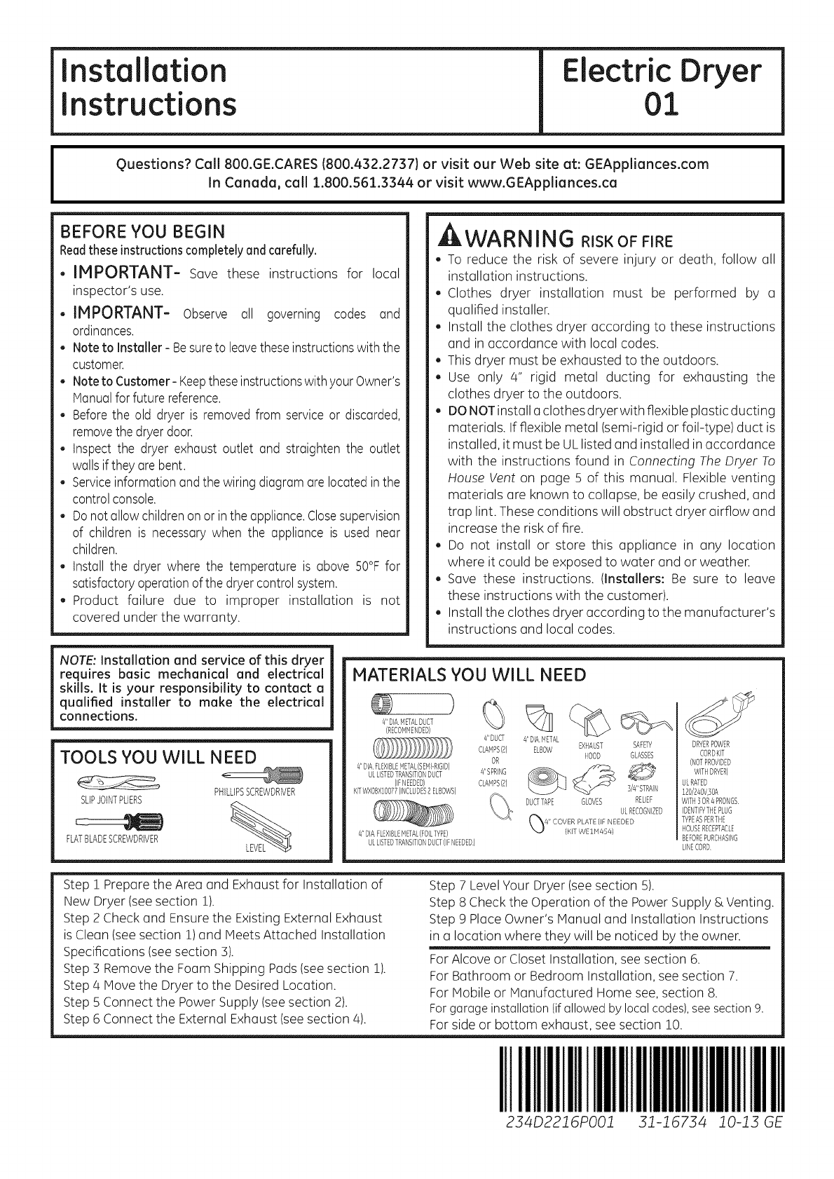
TOOLS YOU WILL NEED
PHILLIPSSCREWDRIVER
SLIPJOINTPLIERS
FLATBLADESCREWDRIVER
MATERIALS YOU WILL NEED
4"DIAM_TALDUCT V/ll
(RECOMUENDED) "--L4J
8"DUCT #'DIA METAL
CLAMPS(2) ELBOW
OR
#'SPRING
CLAMPS(2)
4"DIAFLEXIBLEMETAL(SEMI-RIGID)
ULLISTEDTRANSITIONDUCT
(IFNEEDED)
KITWXOBX1BB77(INCLUDES2ELBOWS)
4"DIAFLEXIBLEMETAL(FOILTYPE)
ULLISTEDTRANSITIONDUCT(IFNEEDED)
EXHAUST SAFETY
HOOD GLASSES
DUCTTAPE GLOVES
3/4"STRAIN
RELIEF
ULRECOGNIZED
DRYERPOWER
CORDKIT
(NOTPROVIDED
WITHDRYER)
ULRATED
120/240V3OA
WITH3OR4PROGS
IDENTIFYTHEPLUG
TYPEASPERTHE
HOUSERECEPTACLE
BEFOREPURCHASING
LINECORD
Step ! Prepare the Area and Exhaust for Installation of
New Dryer (see section 1).
Step 2 Check and Ensure the Existing External Exhaust
is Clean (see section 1)and Meets Attached Installation
Specifications (see section 3).
Step 3 Remove the Foam Shipping Pads (see section 1).
Step 4 Hove the Dryer to the Desired Location.
Step 5 Connect the Power Supply (see section 2).
Step 6 Connect the External Exhaust (see section 4).
Step 7 Level Your Dryer (see section 5).
Step 8 Check the Operation of the Power Supply & Venting.
Step 9 Place Owner's Manual and Installation Instructions
in a location where they will be noticed by the owner.
For Alcove or Closet Installation, see section 6.
For Bathroom or Bedroom Installation, see section 7.
For Mobile or Manufactured Home see, section 8.
Forgarage installation (ifallowed by local codes),see section9.
For side or bottom exhaust, see section 10.
IIIIIIIIIIIiill
234D22JGPOOJ IIIIII
3"1-'16734 JO-J5 GE
Installation instructions
Minimum Clearance Other Than Alcove or Closet Installation
Minimum clearance to combustible surfaces and for air opening are: 0 in. clearance both sides and i in. rear.
Consideration must be given to provide adequate clearance for installation and service.
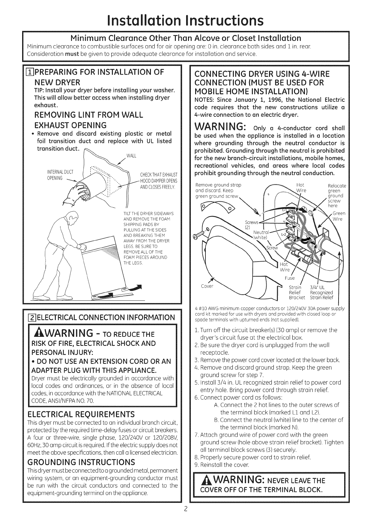
FIIPREPARING FOR INSTALLATION OF
NEW DRYER
TIP: Install your dryer before installing your washer.
This will allow better access when installing dryer
exhaust.
REMOVING LINT FROM WALL
EXHAUST OPENING
, Remove and discard existing plastic or metal
foil transition duct and replace with UL listed
transition duct.
WALL
INTERNALDUCT CHECKTHATEXHAUST
OPENING ../HOOD DAMPEROPENS
ANDCLOSESFREELY.
TILTTHE DRYERSIDEWAYS
AND REMOVETHE FOAM
SHIPPING PADS BY
PULLING ATTHE SIDES
AND BREAKING THEM
AWAY FROM THE DRYER
LEGS. BE SURE TO
REMOVE ALL OF THE
FOAM PIECESAROUND
THE LEGS,
F21ELECTRICAL CONNECTION INFORMATION
t WARNING - TOREDUCETHE
RISK OF FIRE, ELECTRICAL SHOCK AND
PERSONAL INJURY:
,, DO NOT USE AN EXTENSION CORD OR AN
ADAPTER PLUG WITH THIS APPLIANCE.
Dryer must be electrically grounded in accordance with
local codes and ordinances, or in the absence of local
codes, in accordance with the NATIONALELECTRICAL
CODE,ANSI/NFPANO.70.
ELECTRICAL REQUIREMENTS
This dryer must be connected to an individual branch circuit,
protected by the requiredtime-delay fuses or circuit breakers.
A four or three-wire, single phase, 120/240V or 120/208V,
60Hz,:30amp circuit is required. Ifthe electric supply does not
meet the above specifications,then call a licensedelectrician.
GROUNDING INSTRUCTIONS
Thisdryer must beconnected to agrounded metal, permanent
wiring system, or an equipment-grounding conductor must
be run with the circuit conductors and connected to the
equipment-grounding terminal on the appliance.
CONNECTING DRYER USING 4-WIRE
CONNECTION (MUST BE USED FOR
MOBILE HOME INSTALLATION)
NOTES: Since January :1, :1996, the National Electric
code requires that the new constructions utilize a
4-wire connection to an electric dryer.
WARNING: Onlyo 4-conductorcordshall
be used when the appliance is installed in a location
where grounding through the neutral conductor is
prohibited. Grounding through the neutral is prohibited
for the new branch-circuit installations, mobile homes,
recreational vehicles, and areas where local codes
prohibit grounding through the neutral conduction.
Remove ground strop _ Hot Relocote
and discord, Keep [___. _Wire green
green ground screw _ _ ,/ _'--_k ground
, _/.._. "_ here
_ Hot _;/. V_I. .
c I _ II_-j
over_ } _ Stroin 3/4" UL
/I Relief Recognized
-- _ Bracket Stroin Relief
4 #t0 AWG minimum copper conductors or 120/240V 30A power supply
cord kit marked for use with dryers and provided with closed loop or
spode terminals with upturned ends (not supplied).
!. Turn off the circuit breaker(s)(30 amp)or remove the
dryer's circuit fuse at the electrical box,
2. Be sure the dryer cord is unplugged from the wall
receptacle,
3. Removethe power cord cover located at the lower back.
4. Remove and discard ground strap. Keep the green
ground screw for step 7.
5. Install 3/4 in. UL recognized strain relief to power cord
entry hole. Bring power cord through strain relief.
6. Connect power cord as follows:
A. Connect the 2 hot lines to the outer screws of
the terminal block (marked L! and L2).
B. Connect the neutral (white) line to the center of
the terminal block (marked N).
7. Attach ground wire of power cord with the green
ground screw (hole above strain relief bracket). Tighten
all terminal block screws (3)securely.
8. Properly secure power cord to strain relief.
9. Reinstall the cover.
I WARNING: NEVER LEAVE THE !
COVER OFF OF THE TERMINAL BLOCK.
2
Installation instructions
CONNECTING DRYER USING 3-WIRE
CONNECTION
If required, by local code, install external ground {not provided) to
grounded metal, cold water pipe, or other established ground determined
by a qualified electrician.
Hot
Wire
Green Ground Screw
& Ground Strap
Cover
Fuse
Strain 3/4" UL
Relief Recognized
Bracket Strain Relief
3 #10 AWG minimum copper conductors or 120/240V 30A power supply
cord kit marked for use with dryers and provided with closed loop or
spade terminals with upturned ends (not supplied).
3-wire Connection
Not for use in Canada.
DO NOTuse for Mobile Home Installations.
NOTfor use on new construction.
NOTfor use on recreational vehicles.
NOTfor use in areas where local codes prohibit grounding
through the neutral conduction.
1.Turn off the circuit breaker(s)(30 amp) or remove the
dryer's circuit fuse at the electrical box.
2. Be sure the dryer cord is unplugged from the wall.
3. Remove the power cord cover located at the lower back.
4. Install 3/4 in. UL recognized strain relief to power cord
entry hole. Bring power cord through strain relief.
5. Connect power cord as follows:
A. Connect the 2 hot lines to the outer screws of
the terminal block (marked L1 and L2).
B.Connect the neutral (white) line to the center of
the terminal block (marked N).
6. Be sure ground strap is connected to neutral (center)
terminal of block and to green ground screw on cabinet
rear. Tighten all terminal block screws (3)securely.
7. Properly secure power cord to strain relief.
8. Reinstall the cover.
WARNING: NEVER LEAVE THE
COVER OFF OF THE TERMINAL BLOCK.
[-3] EXHAUST INFORMATION
i WARNING -IN CANADAANDINTHE
UNITED STATES, THE REQUIRED EXHAUST
DUCT DIAMETER IS 4 IN (102mm). DO NOT
USE DUCT LONGER THAN SPECIFIED IN THE
EXHAUST LENGTH TABLE.
Usingexhaust longer than specified length will:
. Increase the drying times and the energy cost.
, Reducethe dryer life.
, Accumulate lint, creating a potential fire hazard.
The correct exhaust installation is YOUR
RESPONSIBILITY.Problems due to incorrect installation
are not covered by the warranty.
Removeand discard existing plastic or metal foil transition
duct and replace with ULlisted transition duct.
The MAXIMUMALLOWABLEduct length and number of
bends of the exhaust system depends upon the type of
duct, number of turns, the type of exhaust hood (wall cap),
and all conditions noted below.The maximum duct length
for rigid metal duct is shown inthe table below.
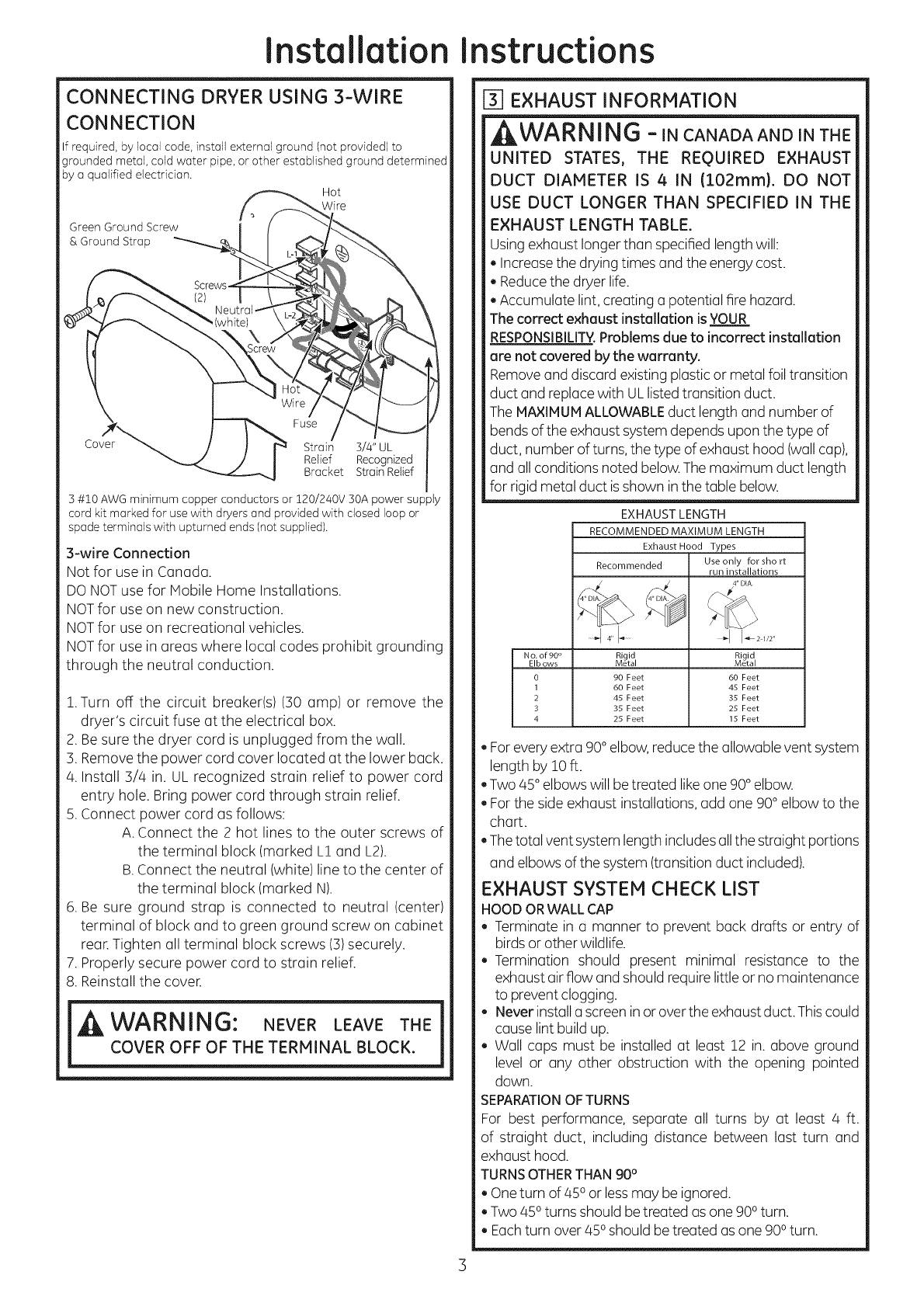
EXHAUST LENGTH
RECOMMENDED MAXIMUM LENGTH
Exhaust Hood Types
Recommended Use only for short
run installations
......14I....... I I--2"2
No. of 90 ° Rigid Rigid
EIb ows Metal Metal
0 90 Feet 60 Feet
1 60 Feet 45 Feet
2 45 Feet 35 Feet
3 35 Feet 25 Feet
4 25 Feet 15 Feet
. Forevery extra 90° elbow, reduce the allowable vent system
length by 10ft.
. Two/45° elbows will betreated likeone 90° elbow.
. Forthe side exhaust installations, add one 90° elbow to the
chart.
, Thetotal vent system length includesall the straight portions
and elbows of the system (transition duct included).
EXHAUST SYSTEM CHECK LIST
HOOD OR WALL CAP
, Terminate in a manner to prevent back drafts or entry of
birds or other wildlife.
. Termination should present minimal resistance to the
exhaust air flow and should requirelittle or no maintenance
to prevent clogging.
. Never install a screenin or over the exhaustduct. Thiscould
cause lint build up.
, Wall caps must be installed at least !2 in. above ground
level or any other obstruction with the opening pointed
down.
SEPARATIONOFTURNS
For best performance, separate all turns by at least 4 ft.
of straight duct, including distance between last turn and
exhaust hood.
TURNSOTHERTHAN 90°
. Oneturn of 450or lessmay be ignored.
. Two 450turns should be treated as one 900turn.
. Eachturn over 450should betreated as one 900turn.
3
Installation instructions
EXHAUST INFORMATION (cont)
SEALING OFJOINTS
, All joints should be tight to avoid leaks. The male end of
each section of duct must point away from the dryer.
, Do not assemble the ductwork with fasteners that
extend into the duct. They will serve as a collection point
for lint.
, Duct joints can be made air and moisture-tight by
wrapping the overlapped joints with duct tape.
, Horizontal runs should slope down toward the outdoors
1/4 inch per foot
INSULATION
Duct work that runs through an unheated area or is near air
conditioning should be insulated to reduce condensation
and lint build-up.
F4-]EXHAUST CONNECTION
WARNING - TOREDUCE
THE
RISK OF FIRE OR PERSONAL INJURY:
. This clothes dryer must be exhausted to the
outdoors.
. Useonly 4" rigid metal ducting for the home exhaust
duct.
. Use only 4" rigid metal or UL-listed flexible metal
(semi-rigid or foil-type) duct to connect the dryer
to the home exhaust duct. It must be installed
in accordance with the instructions found in
"Connecting The Dryer To House Vent" on page 5 of
this manual.
. Do not terminate exhaust in o chimney, a wall,
a ceiling, gas vent, crawl space, attic, under an
enclosed floor, or in any other concealed space
of a building. The accumulated lint could create a
potential fire hazard.
. Never terminate the exhaust into o common duct
with a kitchen exhaust system. A combination of
grease and lint creates o potential fire hazard.
. Do not use duct longer than specified in the exhaust
length table. Longer ducts can accumulate lint,
creating a potential fire hazard.
. Never install a screen in or over the exhaust duct.
This will cause lint to accumulate, creating a
potential fire hazard.
. Do not assemble ductwork with any fasteners
that extend into the duct. These fasteners can
accumulate lint, creating a potential fire hazard.
. Do not obstruct incoming or exhausted air.
. Provide an access for inspection and cleaning of
the exhaust system, especially at turns and joints.
Exhaust system shall be inspected and cleaned at
least once a year.
THIS DRYER COMES READY FOR REAR
EXHAUSTING. IF SPACE IS LIMITED, USE
THE INSTRUCTIONS IN SECTION iO TO
EXHAUST DIRECTLY FROM THE SIDES
OR BOTTOM OF THE CABINET.
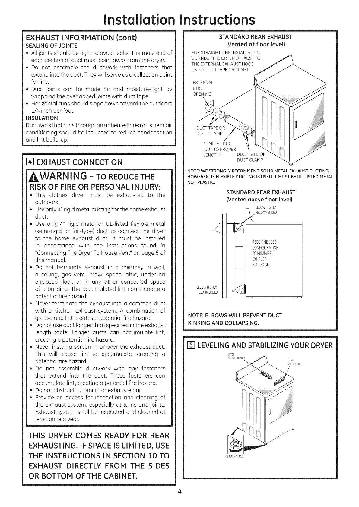
STANDARD REAREXHAUST
(Vented at floor level}
FOR STRAIGHT LINE INSTALLATION,
CONNECT THE DRYER EXHAUST TO
THE EXTERNAL EXHAUST HOOD
USING DUCT TAPE OR CLAMP.
EXTERNAL
DUCT
OPENING
DUCT TAPE OR
DUCT CLAMP
4" METAL DUCT
(CUT TO PROPER
LENGTH) DUCT TAPE OR
DUCT CLAMP
NOTE: WE STRONGLY RECOMMEND SOLID METAL EXHAUST DUCTING.
HOWEVER, IF FLEXIBLE DUCTING IS USED IT MUST BE UL-LISTED METAL
NOT PLASTIC.
(
ELBOWHIGHLY
RECOMMENDED-
STANDARD REAR EXHAUST
(Vented above floor level}
ELBOWHIGHLY
_ RECOMMENDED
RECOMMENDED
CONFIGURATION
TOMINIMIZE
EXHAUST
BLOCKAGE.
r-m
NOTE: ELBOWS WILL PREVENT DUCT
KINKING AND COLLAPSING.
rs] LEVELING AND STABILIZING YOUR DRYER
LEVELNG LEGS
4
Installation instructions
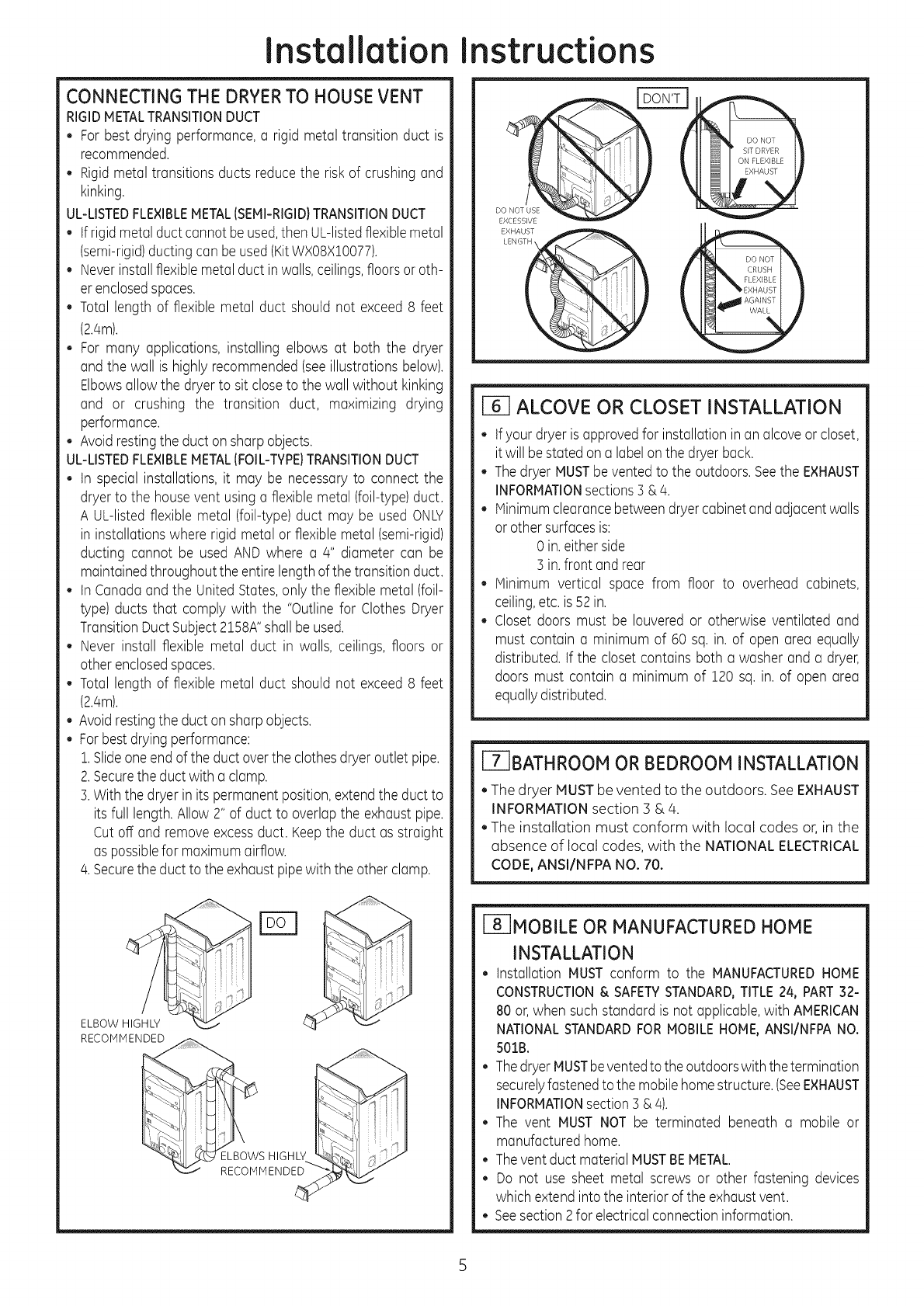
CONNECTING THE DRYERTO HOUSE VENT
RIGIDMETALTRANSITIONDUCT
* For best drying performance,a rigid metal transition duct is
recommended.
, Rigidmetal transitions ducts reduce the riskof crushingand
kinking.
UL-LISTEDFLEXIBLEMETAL(SEMI-RIGID}TRANSITIONDUCT
tfrigid metalduct cannot beused,then UL-listedflexiblemetal
(semi-rigid)ducting can beused(KitWX08X!0077).
Neverinstallflexiblemetal duct in walls,ceilings,floorsor oth-
erenclosedspaces.
Total length of flexible metal duct should not exceed8 feet
(2.4m).
For many applications, installing elbows at both the dryer
and the wall is highly recommended(seeillustrations below).
Elbowsallow the dryer to sit closeto the wall without kinking
and or crushing the transition duct, maximizing drying
performance.
Avoid restingthe duct on sharp objects.
UL-LISTEDFLEXIBLEMETAL(FOIL-TYPE}TRANSITIONDUCT
,tn special installations, it may be necessaryto connect the
dryer to the house vent using a flexible metal (foil-type)duct.
A UL-listedflexible metal (foil-type)duct may be used ONLY
in installationswhere rigid metal or flexiblemetal (semi-rigid)
ducting cannot be used AND where a 4" diameter can be
maintainedthroughout the entire lengthof the transition duct.
tn Canada and the United States,only the flexible metal (foil-
type) ducts that comply with the "Outline for Clothes Dryer
TransitionDuct Subject2158A"shall be used.
, Never install flexible metal duct in walls, ceilings, floors or
other enclosedspaces.
Total length of flexible metal duct should not exceed8 feet
(2.4m).
, Avoidrestingthe duct onsharp objects.
, For bestdrying performance:
1.Slideoneend of the duct overthe clothes dryer outlet pipe.
2.Securethe duct with a clamp.
3.With the dryer in its permanentposition,extendthe duct to
its full length.Allow 2" of duct to overlap the exhaust pipe.
Cut off and removeexcessduct. Keepthe duct as straight
as possiblefor maximumairflow.
4. Securethe duct to the exhaust pipewith the other clamp.
ELBOW
RECOMMENDED
__S HIGHLY
RECOMMENDED
EXCESSIVE
EXHAUST _)LENG_ DO NOT
CRUSH
FLEXIBLE
EXHAUST
AGAINST
ALCOVE OR CLOSET INSTALLATION
• tfyour dryer is approvedfor installation in an alcoveor closet,
it will bestated on a labelon the dryer back.
The dryer MUSTbevented to the outdoors. Seethe EXHAUST
INFORMATIONsections3 &/4.
Minimumclearancebetweendryer cabinetandadjacent walls
or other surfacesis:
0 in. either side
3 in. front and rear
Minimum vertical space from floor to overhead cabinets,
ceiling,etc.is 52in.
Closet doors must be Iouvered or otherwise ventilated and
must contain a minimum of 60 sq. in. of open area equally
distributed, tf the closet contains both a washer and a dryer,
doors must contain a minimum of 120 sq. in. of open area
equally distributed.
F7-1BATHROOM OR BEDROOM INSTALLATION
. The dryer MUSTbe vented to the outdoors. SeeEXHAUST
iNFORMATION section 3 &/4.
The installation must conform with local codes or, in the
absence of local codes, with the NATIONAL ELECTRICAL
CODE, ANSI/NFPA NO. 70.
FS]MOBILE OR MANUFACTURED HOME
INSTALLATION
• installation MUSTconform to the MANUFACTUREDHOME
CONSTRUCTION& SAFETYSTANDARD,TITLE24, PART32-
80 or, when suchstandard is not applicable,with AMERICAN
NATIONALSTANDARDFORMOBILEHOME,ANSI/NFPANO.
501B.
• ThedryerMUSTbeventedto the outdoorswith thetermination
securelyfastenedto the mobilehome structure.(SeeEXHAUST
INFORMATIONsection 3 &4).
The vent MUST NOT be terminated beneath a mobile or
manufactured home.
Thevent duct material MUSTBEMETAL.
Do not use sheet metal screws or other fastening devices
which extendinto the interior of the exhaustvent.
Seesection 2for electrical connectioninformation.
5
Installation instructions
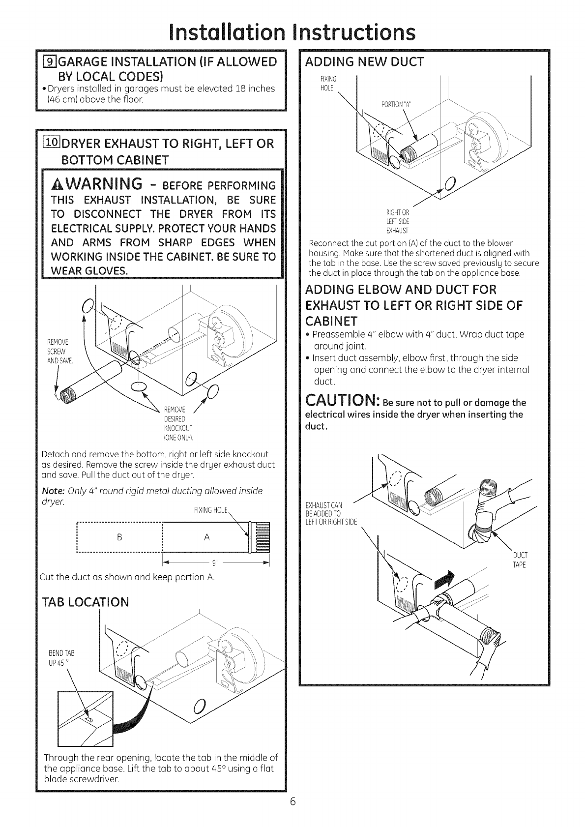
F_GARAGE INSTALLATION (IF ALLOWED
BY LOCAL CODES)
. Dryers installed in garages must be elevated 18 inches
(46 cm) above the floor.
[ZO]DRYER EXHAUST TO RIGHT, LEFT OR
BOTTOM CABINET
AWARNING - BEFOREPERFORMING
THIS EXHAUST INSTALLATION, BE SURE
TO DISCONNECT THE DRYER FROM ITS
ELECTRICAL SUPPLY. PROTECT YOUR HANDS
AND ARMS FROM SHARP EDGES WHEN
WORKING INSIDE THE CABINET. BE SURE TO
WEAR GLOVES.
REMOVE
SCREW
ANDSAVE.
REMOVE,_
DESIRED
KNOCKOUT
(ONEONLY).
Detach and remove the bottom, right or left side knockout
as desired. Remove the screw inside the drger exhaust duct
and save. Pull the duct out of the drger.
Note: Only 4" round rigid metal ducting allowed inside
dryer. FIXINGHOLE
B A
J_ 9"
Cut the duct as shown and keep portion A.
TAB LOCATION
BENDTAB
UP45 o
Through the rear opening, locate the tab in the middle of
the appliance base. Lift the tab to about 450 using a flat
blade screwdriver.
ADDING NEW DUCT
FIXING
HOLE
PORTION"A"
RIGHTOR
LEFTSIDE
EXHAUST
Reconnectthe cut portion (A)of the duct to the blower
housing.Makesure that the shortenedduct is alignedwith
the tab inthe base.Usethe screw saved previouslyto secure
the duct in place through the tab on the appliance base.
ADDING ELBOW AND DUCT FOR
EXHAUST TO LEFT OR RIGHT SIDE OF
CABINET
. Preassemble 4" elbow with 4" duct. Wrap duct tape
around joint.
Insert duct assembly, elbow first, through the side
opening and connect the elbow to the dryer internal
duct.
CAUTION: Be sure not to pull or damage the
electrical wires inside the dryer when inserting the
duct.
EXHAUSTCAN
BEADDEDTO
LEFTORRIGHTSIDE\
j_
DUCT
TAPE
6
Installation instructions
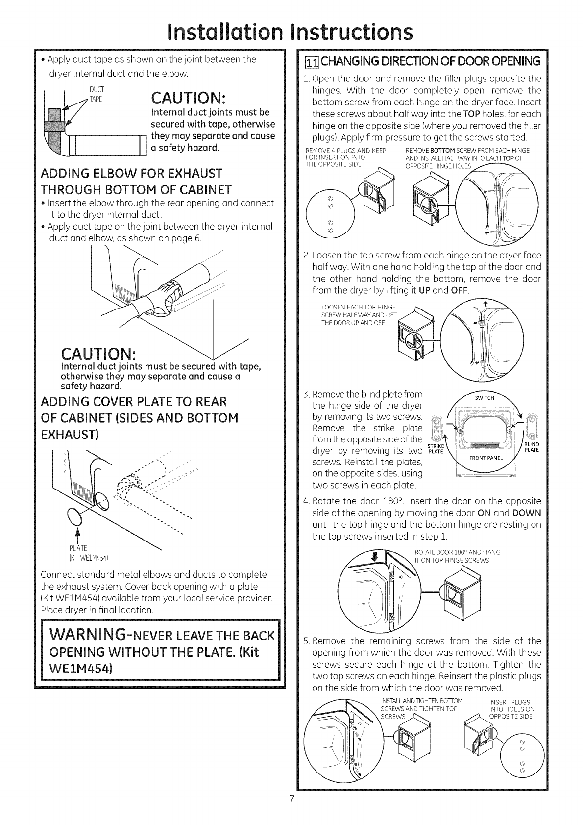
. Apply duct tape as shown on the joint between the
dryer internal duct and the elbow.
DUCT CAUTION:
Internal duct joints must be
secured with tape, otherwise
H hey may separate and cause
asafety hazard.
ADDING ELBOW FOR EXHAUST
THROUGH BOTTOM OF CABINET
. Insert the elbow through the rear opening and connect
it to the dryer internal duct.
. Apply duct tape on the joint between the dryer internal
duct and elbow, as shown on page 6.
J
CAUTION:
Internal duct joints must be secured with tape,
otherwise they may separate and cause a
safety hazard.
ADDING COVER PLATE TO REAR
OF CABINET {SIDES AND BOTTOM
EXHAUST}
PLATE
(KffWE1M454)
Connect standard metal elbows and ducts to complete
the exhaust system. Cover back opening with a plate
(Kit WE1M454) available from your local service provider.
Place dryer in final location.
WARNING-NEVER LEAVE THE BACK
OPENING WITHOUT THE PLATE. (Kit
WEIM454)
[_CHANGING DIRECTIONOF DOOROPENING
1.Open the door and remove the filler plugs opposite the
hinges. With the door completely open, remove the
bottom screw from each hinge on the dryer face. Insert
these screws about half way into the TOP holes,for each
hinge on the opposite side (where you removed the filler
plugs). Apply firm pressure to get the screws started.
REMOVE/4 PLUGS AND KEEP REMOVE BOTTOM SCREW FROM EACH HINGE
FOR INSERTION INTO AND INSTALL HALF WAY INTO EACH TOP OF
THE OPPOSITE SIDE OP ....
2. Loosen the top screw from each hinge on the dryer face
halfway. With one hand holding the top of the door and
the other hand holding the bottom, remove the door
from the dryer by lifting it UP and OFF.
LOOSEN EACH TOP HINGE
SCREW HALF WAY AND LIFT
THE DOOR UP AND OFF
3.
4.
Removethe blind plate from
the hinge side of the dryer
by removing its two screws.
Remove the strike plate
from the opposite side of the
dryer by removing its two
screws. Reinstall the plates,
on the opposite sides, using
two screws in each plate.
Rotate the door 1800. Insert the door on the opposite
side of the opening by moving the door OI/and DOWN
until the top hinge and the bottom hinge are resting on
the top screws inserted in step 1.
ROTATE DOOR 180 ° AND HANG
5. Remove the remaining screws from the side of the
opening from which the door was removed. With these
screws secure each hinge at the bottom. Tighten the
two top screws on each hinge. Reinsert the plastic plugs
on the side from which the door was removed.
INSTALLAN D TIGHTEN BOTTOM
SCREWS AND TIGHTEN TOP
INSERT PLUGS
INTO HOLES ON
OPPOSITE SI DE
7

Installation Instructions
[_ CONNECTING INLET HOSES (on some
models)
To produce steam, the dryer must connect to the cold
water supply. Since the washer must also connect to the
cold water, a ",7"connector is inserted to allow both inlet
hoses to make that connection at the same time.
NOTE: Use the new inlet hoses provided; never use old
hoses.
1. Turn the cold water faucet off. Remove the washer inlet
hose from the washer fill valve connector (cold).
2. Ensure the rubber fiat washer is in place and screw the
female coupling of the short hose onto the washer fill
valve connector. Tighten by hand until firmly seated.
3. Attach the female end of the '"7" connector to the mule
coupling of the short hose. Ensurethe rubber fiat washer
is in place. Tighten by hand until firmly seated.
4. Insert the filter screen in the coupling of the washer's
inlet hose. If a rubber fiat washer is already in place
remove it before installing the filter screen. Attach this
coupling to one male end of the '"7" connector. Tighten
by hand until firmly seated.
5. Ensure the rubber fiat washer is in place and attach the
dryer's long inlet hose to the other male end of the '"7"
connector. Tighten by hand until firmly seated.
6. Ensure the rubber fiat washer is in place and attach
the other end of the dryer's long inlet hose to the fill
valve connector at the bottom of the dryer back panel.
Tighten by hand until firmly seated.
[] CONNECTING INLET HOSES {cont.}
7. Using pliers, tighten all the couplings with an additional
two-thirds turn.
NOTE: Do not overtighten. Damage to the couplings may
result.
8. Turn the water faucet on.
9. Check for leaks around the '"7" connector, faucet and
hose couplings.
WATER SUPPLY REQUIREMENTS
Hot and cold water faucets MUSTbe installed within 42 in.
(107 cm) of your washer's water inlet. The faucets MUST
be 3/4 in. (1.9 cm) garden hose-type so inlet hoses can
be connected. Water pressure MUSTbe between 10 and
120 pounds per square inch. Your water department can
advise you of your water pressure.
NOTE:Awater softener is recommended to reduce buildup
of scale inside the steam generator if the home water
supply is very hard.
[] SERVICING
kWARNING - LABEL ALL WIRES
PRIOR TO DISCONNECTING WHEN
SERVICING CONTROLS. WIRING
ERRORS CAN CAUSE IMPROPER AND
DANGEROUS OPERATION AFTER
SERVICI NG/I NSTALLATI O N.
For servicing phone numbers for replacement parts, and
other information, refer to Owner's Manual or visit our
Web site.
REGISTERYOUR NEW APPLIANCE TO RECEIVEANY
IMPORTANT PRODUCT NOTIFICATIONS.
Pleose go to www.GEAppliances.com or moil in your
Product Registrotion Cord.
For questions on installation, call: 800.626.2000 (US)or
800-561-3344 (Canada).
8
