GE GLD2800V00WW User Manual DISHWASHER Manuals And Guides 1108709L
User Manual: GE GLD2800V00WW GLD2800V00WW GE DISHWASHER - Manuals and Guides View the owners manual for your GE DISHWASHER #GLD2800V00WW. Home:Kitchen Appliance Parts:GE Parts:GE DISHWASHER Manual
Open the PDF directly: View PDF ![]() .
.
Page Count: 16
_ _ ° r¸_i _L_+° _._-._
_ #_'J_'_c__ _ _]I/ /II_]
Appliances
Installation Instructions
Built-In Dishwasher
If you have questions, call 800.GE.CARES{800.432.2737) or visit our Website at: GEAppliances.com.
In Canada, please call 1.800.561.3344or visit www.geappliances.ca
BEFORE YOU BEGIN
Read these instructions completely and
carefully.
IM PORTANT - Observe allgoverning codes and
ordinances.
• Note to Installer - Be sure to leave these instructions for the
consumer's and local inspector's use.
• Note to Consumer - Keep these instructions with your
Owner's Manual for future reference.
• Skill Level - Installation of this dishwasher requires
basic mechanical, electrical and plumbing skills. Proper
installation is the responsibility of the installer. Product
failure due to improper installation is not covered under
the GE Appliance Warranty. See warranty information.
• Completion Time - i to 3 Hours. New installations require
more time than replacement installations.
IM PORTANT - The dishwasher MUST be installed
to allowforfutureremoval from the enclosureifserviceis
required.
If you received a damaged dishwasher, you should immediately
contact your dealer or builder.
Optional Accessories -Seethe Owner's Manual for available
custom panel kits.
FOR YOUR SAFETY
Read and observe all CAUTIONS and WARNINGS shown
throughout these instructions. While performing
installations described in this booklet, gloves, safety glasses
or goggles should be worn.
READ CAREFULLY.
KEEP THESE INSTRUCTIONS.
31-30283 05-11GE
Installation Preparation
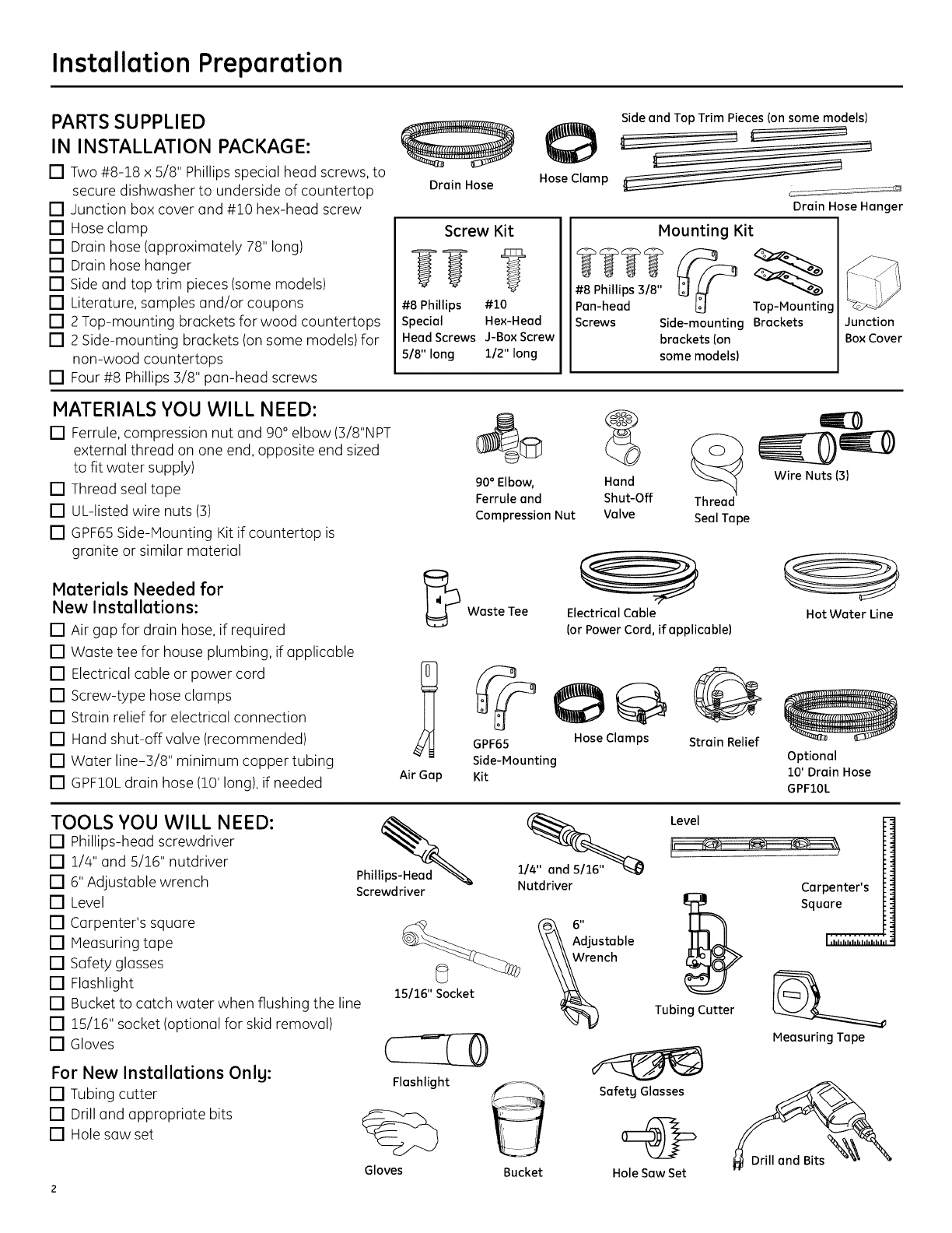
PARTS SUPPLIED
IN INSTALLATION PACKAGE:
[] Two #8-18 x 5/8" Phillips special head screws, to
secure dishwasher to underside of countertop
[] Junction box cover and #10 hex-head screw
[] Hose clamp
[] Drain hose (approximately 78" long)
[] Drain hose hanger
[] Side and top trim pieces (some models)
[] Literature, samples and/or coupons
[] 2 Top-mounting brackets for wood countertops
[] 2 Side-mounting brackets (on some models) for
non-wood countertops
[] Four #8 Phillips 3/8" pan-head screws
Drain Hose HoseClamp
Side and Top Trim Pieces Ion some models)
Drain Hose Hanger
Screw Kit
#8 Phillips #10
Special Hex-Head
HeadScrews J-BoxScrew
5/8" long 112"long
Mounting Kit
#8 Phillips 3/8"
Pan-head Top-Mounting
Screws Side-mounting Brackets
brackets (on
some models)
Junction
Box Cover
MATERIALS YOU WILL NEED:
[] Ferrule, compression nut and 90° elbow (3/8"NPT
external thread on one end, opposite end sized
to fit water supply)
[] Thread seal tape
[] UL-listed wire nuts (:3)
[] GPF65Side-Mounting Kit if countertop is
granite or similar material
Materials Needed for
New Installations:
[] Air gap for drain hose, if required
[] Waste tee for house plumbing, if applicable
[] Electrical cable or power cord
[] Screw-type hose clumps
[] Strain relief for electrical connection
[] Hand shut-off valve (recommended)
[] Water line-3/8" minimum copper tubing
[] GPF10Ldrain hose (10' long), if needed Air Gap
90 ° Elbow, Hand
Ferrule and Shut-Off Thread
Compression Nut Valve Seal Tape
Waste Tee Electrical Cable
(or Power Cord, if applicable)
GPF65 Hose Clamps
Side-Mounting
Kit
Strain Relief
Wire Nuts (3)
Hot Water Line
Optional
10' Drain Hose
GPFIOL
TOOLS YOU WILL NEED:
[] Phillips-head screwdriver
[] 1/4" and 5/16" nutdriver
[] 6" Adjustable wrench
[] Level
[] Carpenter's square
[] Measuring tape
[] Safety glasses
[] Flashlight
[] Bucket to catch water when flushing the line
[] 15/16" socket (optional for skid removal)
[] Gloves
For New Installations Onlg:
[] Tubing cutter
[] Drill and appropriate bits
[] Hole saw set
Phill_
Screwdriver
15/16" Socket
Flashlight
Gloves
Nutdriver
Bucket
Level
Tubing Cutter
SafetyGlasses
Hole Saw Set
Carpenter's
Square
Measuring Tape
Installation Preparation
PREPARE DISHWASHER ENCLOSURE AWARNING:
Toreducethe riskof electric shock,fire,or injury to persons,the
installermust ensurethat the dishwasheris completelyenclosedat
the time of installation.
s4-1/2"_+1/4"
Undersideof
Countertop
to Floor
ThisWall Area
must beFree
of Pipesor
wires
Figure A
MUSTbeEven
With Room Floor
i241,
Min.
Cabinets
.Square
and
Plumb
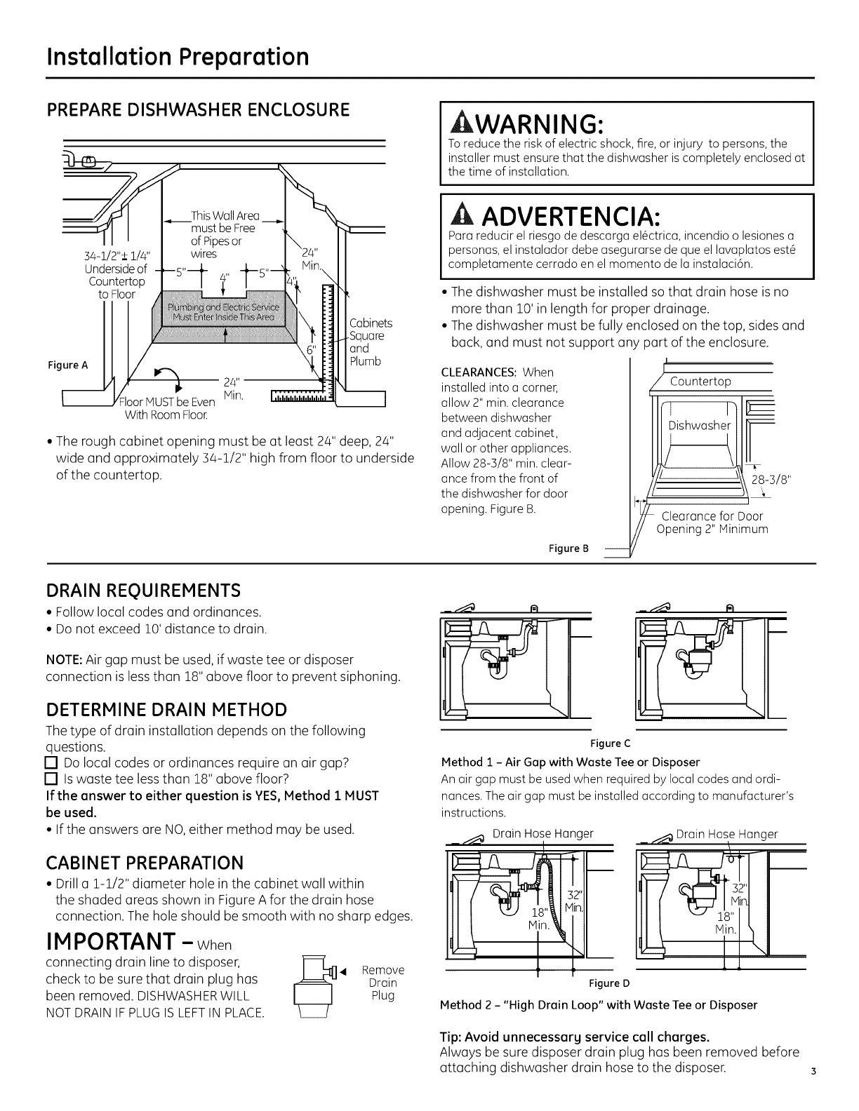
• The rough cabinet opening must be at least 24" deep, 24"
wide and approximately 34-1/2" high from floor to underside
of the countertop.
ADVERTENCIA:
Pororeducirel riesgode descorgoel6ctrico,incendioo lesioneso
personas,el instolodordebeosegurorsedeque el Iovoplotosest6
completomentecerrodo en elmomenta de Io instoloci6n.
• The dishwasher must be installed so that drain hose is no
more than 10' in length for proper drainage.
• The dishwasher must be fully enclosed on the top, sides and
back, and must not support any part of the enclosure.
CLEARANCES: When
installed into a corner,
allow 2" min. clearance
between dishwasher
and adjacent cabinet,
wall or other appliances.
Allow 28-3/8" min. clear-
once from the front of
the dishwasher for door
opening. Figure B.
Figure B
I
Countertop
__ _I-3/8"
/Clearance for Door
Opening2" Minimum
DRAIN REQUIREMENTS
• Follow local codes and ordinances.
•Do not exceed 10' distance to drain.
NOTE:Air gap must be used, if waste tee or disposer
connection is less than 18" above floor to prevent siphoning.
DETERMINE DRAIN METHOD
The type of drain installation depends on the following
questions.
[] Do local codes or ordinances require an air gap?
[] Iswaste tee lessthan Z8" above floor?
If the answer to either question is YES,Method 1 MUST
be used.
• If the answers are NO,either method may be used.
CABINET PREPARATION
• Drill a l-l/2" diameter hole in the cabinet wall within
the shaded areas shown in Figure A for the drain hose
connection. The hole should be smooth with no sharp edges.
IMPORTANT --When
connecting drain line to disposer,
check to be sure that drain plug has
been removed. DISHWASHERWILL
NOTDRAINIF PLUGIS LEFTIN PLACE. 4 Remove
Drain
Plug
___ r_
Figure C
Method 1 - Air Gap with Waste Tee or Disposer
Anair gap must be usedwhen requiredby local codesand ordi-
nances.Theair gap must beinstalledaccordingto manufacturer's
instructions.
__ DrainHoleo Hanger
32"
Figure D
_ _ Drain HoseHanger
Method 2 - "High Drain Loop" with Waste Tee or Disposer
Tip: Avoid unnecessarg service call charges.
Always be sure disposer drain plug has been removed before
attaching dishwasher drain hose to the disposer.
Installation Preparation
PREPARE ELECTRICAL WIRING
IkWARNING:
FOR PERSONAL SAFETY: Remove house fuse or open circuit breaker
beforebeginninginstallation.Do not usean extensioncord or
adapter plugwith this appliance.
/'i Alternate
/t Receptacle
t Location
I \
I \
Ik ADVERTENCIA:
PARASEGURIDADPERSONAL:Quiteelfusible o abrael interruptor
decircuitosantes decomenzarla instalaci6n.No utilice uncable
deextensi6no un enchufeadaptador con esteartefacto.
Electrical Requirements
• This appliance must be supplied with Z20V,60 Hz.,and
connected to on individual properly grounded branch circuit,
protected by o Z5- or 20-ampere circuit breaker or time-delay
fuse.
• Wiring must be 2 wire with ground and rated for 75°C (176°F).
• If the electrical supply does not meet the above requirements,
coil o licensed electrician before proceeding.
Grounding Instructions-Permanent Connection
This appliance must be connected to o grounded metal,
permanent wiring system, or on equipment-grounding
conductor must be run with the circuit conductors and be
connected to the equipment-grounding terminal or lead on
the appliance.
Grounding Instructions-Power Cord Models
This appliance must be grounded. In the event of o malfunction
or breakdown, grounding will reduce the risk of electric shock
by providing o path of least resistance for electric current.
This appliance is equipped with u cord having on equipment-
grounding conductor and o grounding plug. The plug must
be plugged into an appropriate outlet that is installed and
grounded in accordance with oil local codes and ordinances.
AWARNING:
Theimproper connectionof the equipment groundingconductor
can resultin a riskof electric shock.Checkwith a qualified
electrician or servicerepresentativeifyou are indoubt that
the applianceis properlygrounded.
Cabinet
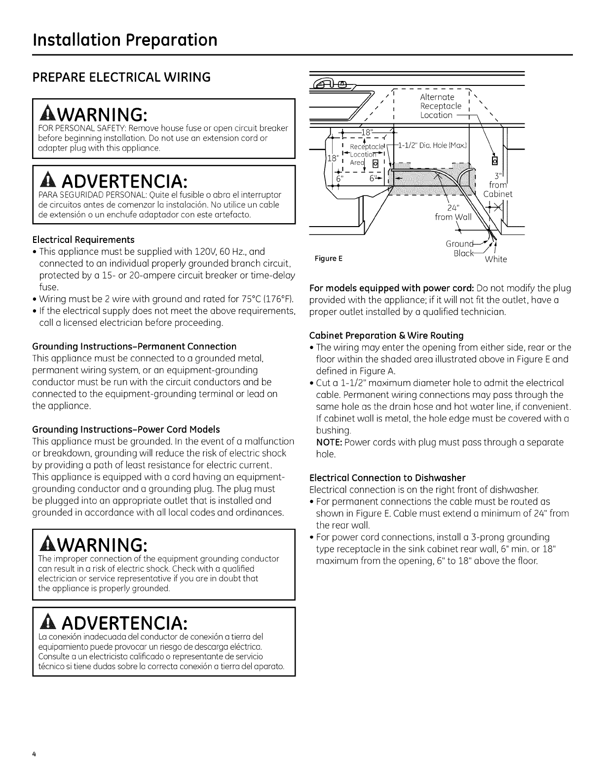
Figure E White
For models equipped with power cord: Do not modify the plug
provided with the appliance; if it will not fit the outlet, have o
proper outlet installed by o qualified technician.
Cabinet Preparation & Wire Routing
• The wiring may enter the opening from either side, rear or the
floor within the shaded area illustrated above in Figure Eand
defined in Figure A.
• Cut o Z-l/2" maximum diameter hole to admit the electrical
cable. Permanent wiring connections may pass through the
same hole as the drain hose and hot water line, if convenient.
If cabinet wall is metal, the hole edge must be covered with o
bushing.
NOTE: Power cords with plug must pass through o separate
hole.
Electrical Connection to Dishwasher
Electrical connection is on the right front of dishwasher.
• For permanent connections the cable must be routed us
shown in Figure E.Cable must extend o minimum of 24" from
the rear wall.
• For power cord connections, install o 3-prong grounding
type receptacle in the sink cabinet rear wall, 6" min. or Z8"
maximum from the opening, 6" to Z8" above the floor.
ADVERTENCIA:
Laconexi6ninadecuadadelconductordeconexi6natierradel
equipamientopuedeprovocarunriesgodedescargael6ctrica.
Consultea unelectricistacalificadoo representantedeservicio
t@cnicositienedudassabrelacorrectaconexi6na tierradelaparato.
Installation Preparation
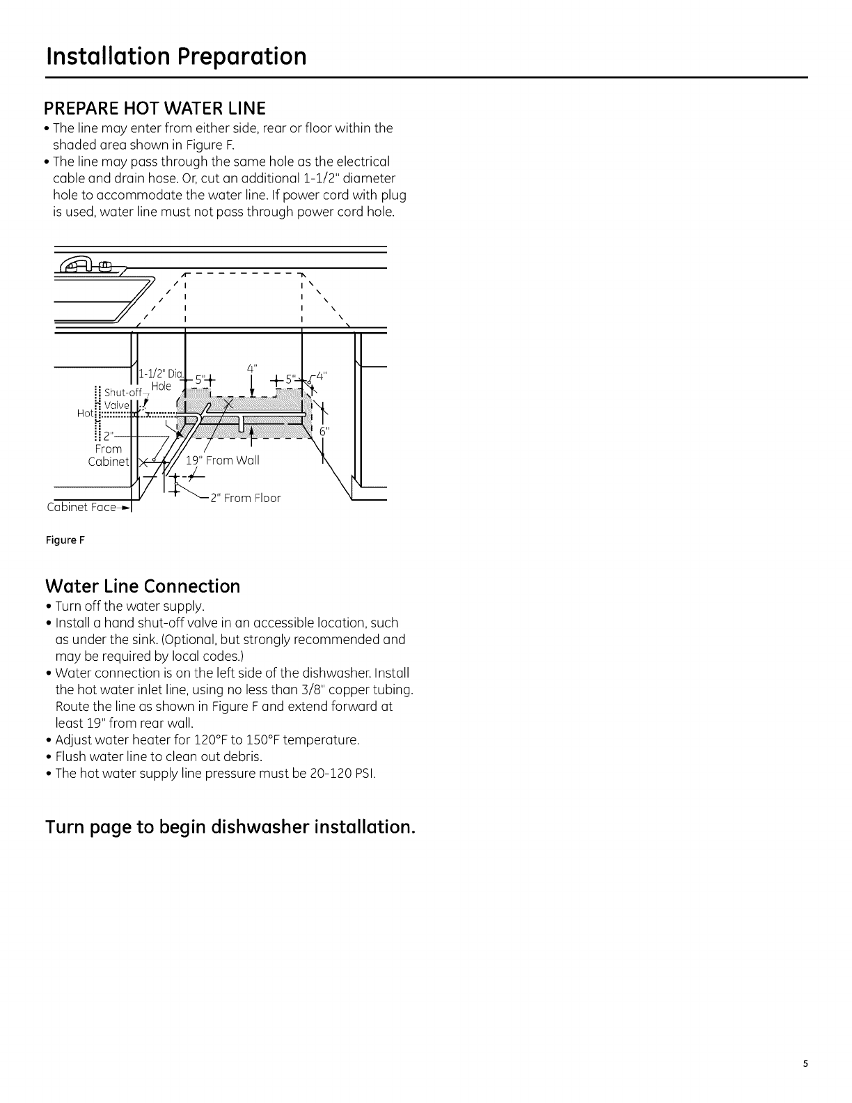
PREPARE HOT WATER LINE
• The line may enter from either side, rear or floor within the
shaded area shown in Figure F.
• The line may pass through the same hole as the electrical
cable and drain hose. Or,cut an additional i-i/2" diameter
hole to accommodate the water line. If power cord with plug
is used, water line must not pass through power cord hole.
ii Shut-off ,
Hot
From
Cabinet
Cabinet
Figure F
2" From Floor
Water Line Connection
•Turn off the water supply.
• Install a hand shut-off valve in an accessible location, such
as under the sink. (Optional, but strongly recommended and
may be required by local codes.)
• Water connection is on the left side of the dishwasher. Install
the hot water inlet line, using no less than 3/8" copper tubing.
Route the line as shown in Figure F and extend forward at
least 19" from rear wall.
• Adjust water heater for 120°F to 150°F temperature.
• Flush water line to clean out debris.
• The hot water supply line pressure must be 20-120 PSI.
Turn page to begin dishwasher installation.
Dishwasher Installation
ACAUTION:
Donot removewood baseuntil you are ready to installthe
dishwasher.Thedishwasherwill tip overwhen the door is opened
if base is removed.
PRECAUCION:
Noquite labasedemaderahastaqueest@listoparainstalarel
lavaplatos.Sisequita labase,ellavaplatossevolcaracuandoseabra
la puerta.
STEP 1: PREPARATION
Locate the items in the installation package and set aside for
use in the listed steps:
• Screw kit - Steps 5 or 18, 12 and 15
• Junction box cover - Step 5 or 18
• Drain hose and clamp - Step 7
• Trim pieces (some models)- Step 11
• Top-mounting brackets - Step 12
• Side-mounting brackets (on some models)- Step 12
• Drain hose hanger - Step 17
• Owner's Manual- Steps 19 and 22
• Product Samples and/or coupons - Step 22
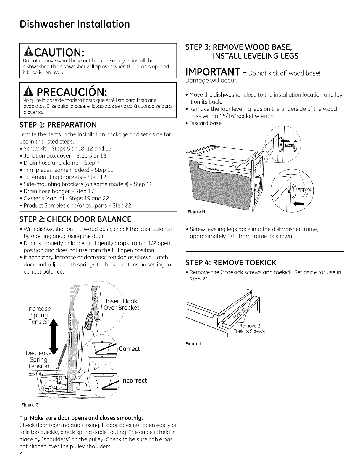
STEP 2: CHECK DOOR BALANCE
• With dishwasher on the wood base, check the door balance
by opening and closing the door.
• Door is properly balanced if it gently drops from a 1/2 open
position and does not rise from the full open position.
• If necessary increase or decrease tension as shown. Latch
door and adjust both springs to the same tension setting to
correct balance.
Increase
Spring
Tension
Insert Hook
Over Bracket
Decreas_ Correct
/
/
Spring
Tension
Figure G
Incorrect
/,
Tip: Make sure door opens and closes smoothly.
Check door opening and closing. If door does not open easily or
falls too quickly, check spring cable routing. The cable is held in
place by "shoulders" on the pulley. Check to be sure cable has
not slipped over the pulley shoulders.
6
STEP 3: REMOVE WOOD BASE,
INSTALL LEVELING LEGS
IMPORTANT -Do not kick offwood base!
Damage will occur.
• Move the dishwasher close to the installation location and lay
it on its back.
• Remove the four leveling legs on the underside of the wood
base with a 15/16" socket wrench.
• Discard base.
Figure H
•Screw leveling legs back into the dishwasher frame,
approximately 1/8" from frame as shown.
STEP 4: REMOVE TOEKICK
• Remove the 2 toekick screws and toekick. Set aside for use in
Step 21.
oekic S ws
Figure I
Dishwasher Installation
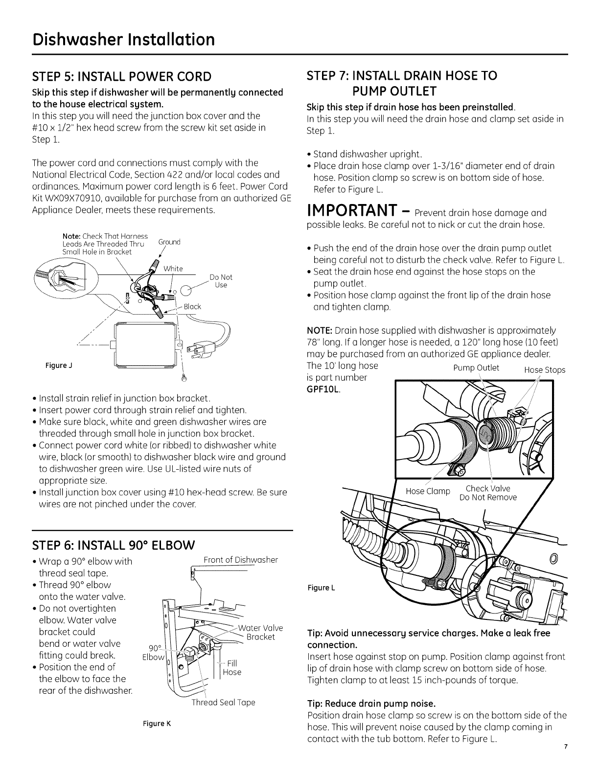
STEP 5: INSTALL POWER CORD
Skip this step if dishwasher will be permanently connected
to the house electrical system.
In this step you will need the junction box cover and the
#10 x 1/2" hex head screw from the screw kit set aside in
Step 1.
The power cord and connections must comply with the
National Electrical Code, Section 422 and/or local codes and
ordinances. Maximum power cord length is 6 feet. Power Cord
Kit WX09X70910, available for purchase from an authorized GE
Appliance Dealer, meets these requirements.
Note: Check That Harness
Leads Are Threaded Thru _Gr°und
Small Hole in Bracket /
Figure J
White
Do Not
Use
Black
•Install strain relief injunction box bracket.
• Insert power cord through strain relief and tighten.
• Make sure black, white and green dishwasher wires are
threaded through small hole injunction box bracket.
• Connect power cord white (or ribbed) to dishwasher white
wire, black (or smooth) to dishwasher black wire and ground
to dishwasher green wire. Use UL-listed wire nuts of
appropriate size.
• Install junction box cover using #10 hex-head screw. Be sure
wires are not pinched under the cover.
STEP 7: INSTALL DRAIN HOSE TO
PUMP OUTLET
Skip this step if drain hose has been preinstalled.
In this step you will need the drain hose and clamp set aside in
Step 1.
• Stand dishwasher upright.
• Place drain hose clamp over 1-3/16" diameter end of drain
hose. Position clamp so screw is on bottom side of hose.
Refer to Figure L.
IMPORTANT - Preventdrainhosedamage and
possibleleaks.Be carefulnottonickorcutthedrainhose.
• Push the end of the drain hose over the drain pump outlet
being careful not to disturb the check valve. Refer to Figure L.
• Seat the drain hose end against the hose stops on the
pump outlet.
• Position hose clamp against the front lip of the drain hose
and tighten clamp.
NOTE: Drain hose supplied with dishwasher is approximately
78" long. If a longer hose is needed, a 120" long hose (10 feet)
may be purchased from an authorized GEappliance dealer.
The 10' long hose Pump Outlet HoseStops
is part number
GPFIOL.
STEP 6: INSTALL 90 ° ELBOW
• Wrap a 90° elbow with
thread seal tape.
• Thread 90° elbow
onto the water valve.
• Do not overtighten
elbow. Water valve
bracket could
bend or water valve
fitting could break. Elbow
• Position the end of
the elbow to face the
rear of the dishwasher.
Figure K
Front of Dishwasher
. Water Valve
Bracket
Thread Seal Tape
@
Figure L
Tip: Avoid unnecessarg service charges. Make a leak free
connection.
Insert hose against stop on pump. Position clamp against front
lip of drain hose with clamp screw on bottom side of hose.
Tighten clamp to at least 15 inch-pounds of torque.
Tip: Reduce drain pump noise.
Position drain hose clamp so screw is on the bottom side of the
hose. This will prevent noise caused by the clump coming in
contact with the tub bottom. Referto Figure L. 7
Dishwasher Installation
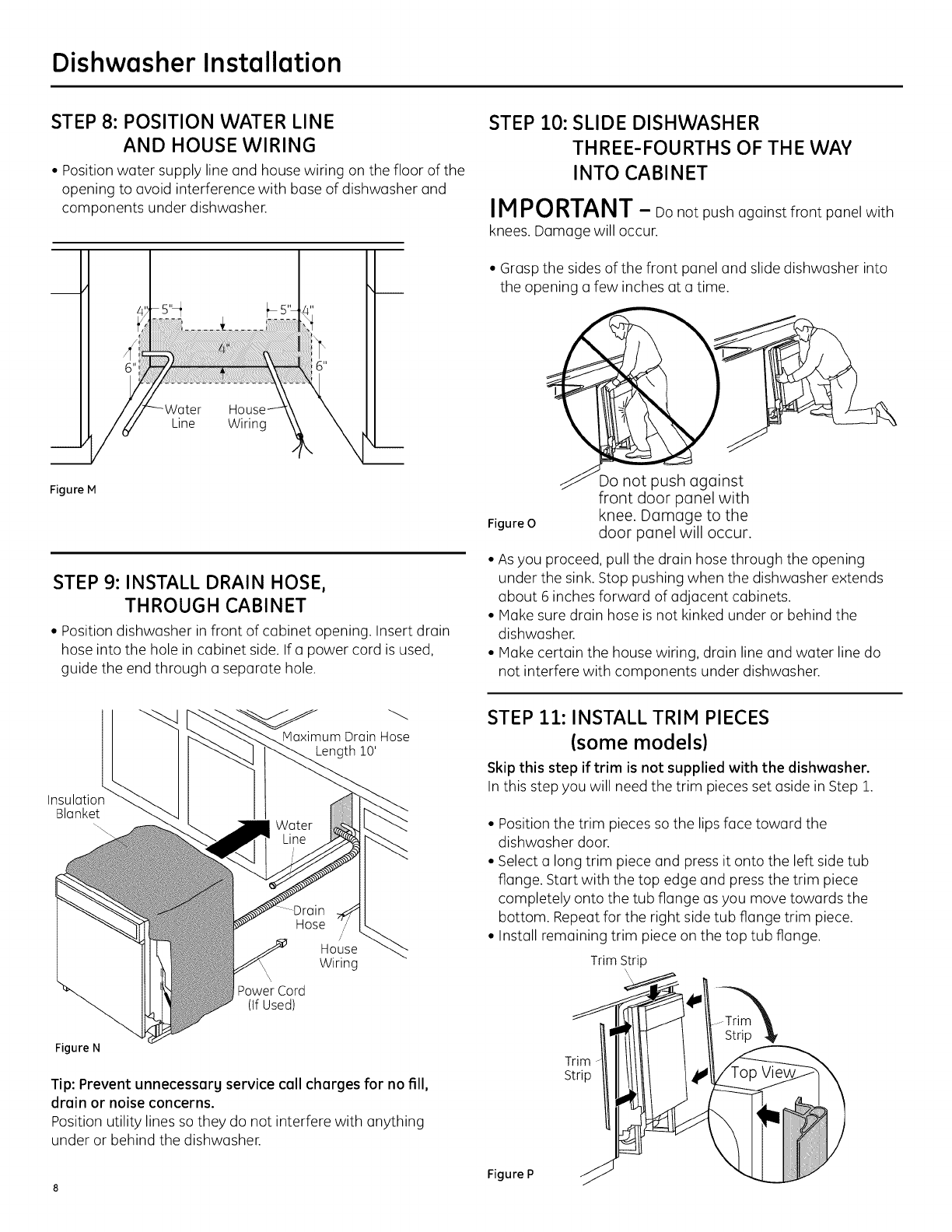
STEP 8: POSITION WATER LINE
AND HOUSE WIRING
• Position water supply line and house wiring on the floor of the
opening to avoid interference with base of dishwasher and
components under dishwasher.
Line Wiring
Figure M
STEP 9: INSTALL DRAIN HOSE,
THROUGH CABINET
• Position dishwasher in front of cabinet opening. Insert drain
hose into the hole in cabinet side. If a power cord is used,
guide the end through a separate hole.
STEP 10: SLIDE DISHWASHER
THREE-FOURTHS OF THE WAY
INTO CABINET
IN PORTANT - oo not push against front panel with
knees. Damage will occur.
• Grasp the sides of the front panel and slide dishwasher into
the opening a few inches at a time.
Figure O
Do not usha ainst
front door panel with
knee. Damage to the
door panel will occur.
• As you proceed, pull the drain hose through the opening
under the sink. Stop pushing when the dishwasher extends
about 6 inches forward of adjacent cabinets.
• Make sure drain hose is not kinked under or behind the
dishwasher.
• Make certain the house wiring, drain line and water line do
not interfere with components under dishwasher.
Maximum Drain Hose
Length 10'
Insulatior
Blanket
Hose /
House
Wiring
PowerCord
(if Used)
Figure N
Tip: Prevent unnecessarg service call charges for no fill,
drain or noise concerns.
Position utility lines so they do not interfere with anything
under or behind the dishwasher.
STEP 11: INSTALL TRIM PIECES
(some models)
Skip this step if trim is not supplied with the dishwasher.
In this step you will need the trim pieces set aside in Step 1.
• Position the trim pieces so the lips face toward the
dishwasher door.
• Select a long trim piece and press it onto the left side tub
flange. Start with the top edge and press the trim piece
completely onto the tub flange as you move towards the
bottom. Repeat for the right side tub flange trim piece.
• Install remaining trim piece on the top tub flange.
TrimStrip
Figure P 1
Dishwasher Installation
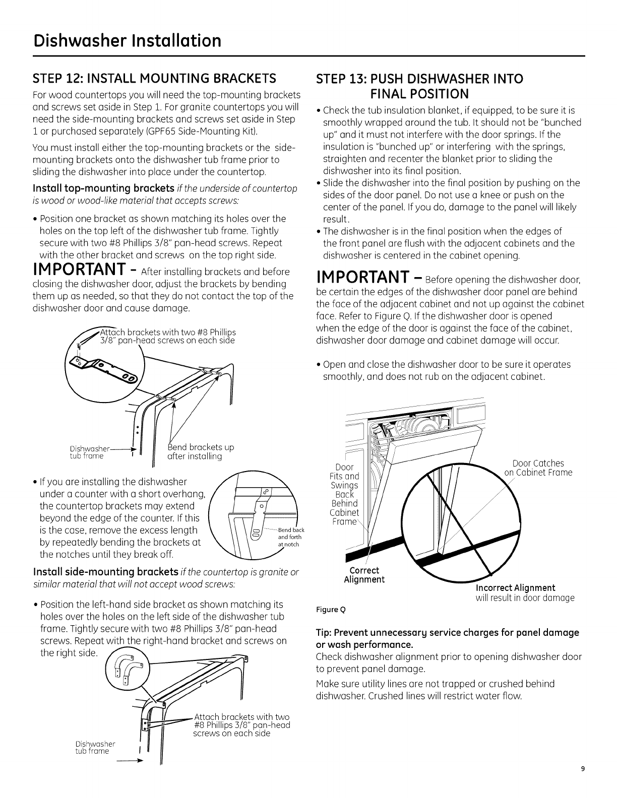
STEP 12: INSTALL MOUNTING BRACKETS
For wood countertops you will need the top-mounting brackets
and screws set aside in Step 1. For granite countertops you will
need the side-mounting brackets and screws set aside in Step
Z or purchased separately (GPF65Side-Mounting Kit).
You must install either the top-mounting brackets or the side-
mounting brackets onto the dishwasher tub frame prior to
sliding the dishwasher into place under the countertop.
Install top-mounting brackets if the underside of countertop
is wood or wood-like material that accepts screws:
• Position one bracket as shown matching its holes over the
holes on the top left of the dishwasher tub frame. Tightly
secure with two #8 Phillips 3/8" pan-head screws. Repeat
with the other bracket and screws on the top right side.
IM PO RTANT -Afterinstalling bracketsandbefore
closing the dishwasher door, adjust the brackets by bending
them up as needed, so that they do not contact the top of the
dishwasher door and cause damage.
Dshwasher ' racketsup
tub frame I after installing
• Ifyou are installing the dishwasher
under a counter with a short overhang,
the countertop brackets may extend
beyond the edge of the counter. If this
is the case, remove the excess length
by repeatedly bending the brackets at
the notches until they break off.
Install side-mounting brackets if the countertop is granite or
similar material that will not accept wood screws:
.... Bend back
and forth
at notch
•Position the left-hand side bracket as shown matching its
holes over the holes on the left side of the dishwasher tub
frame. Tightly secure with two #8 Phillips 3/8" pan-head
screws. Repeat with the right-hand bracket and screws on
the right side. _ ._,_t
__r-" s with two
#8 Phillips3/8" pan-head
screwson eachside
Dishwasher
tub frame I
STEP 13: PUSH DISHWASHER INTO
FINAL POSITION
• Check the tub insulation blanket, if equipped, to be sure it is
smoothly wrapped around the tub. It should not be "bunched
up" and it must not interfere with the door springs. If the
insulation is "bunched up" or interfering with the springs,
straighten and recenter the blanket prior to sliding the
dishwasher into its final position.
• Slide the dishwasher into the final position by pushing on the
sides of the door panel. Do not use a knee or push on the
center of the panel. If you do, damage to the panel will likely
result.
• The dishwasher is in the final position when the edges of
the front panel are flush with the adjacent cabinets and the
dishwasher is centered in the cabinet opening.
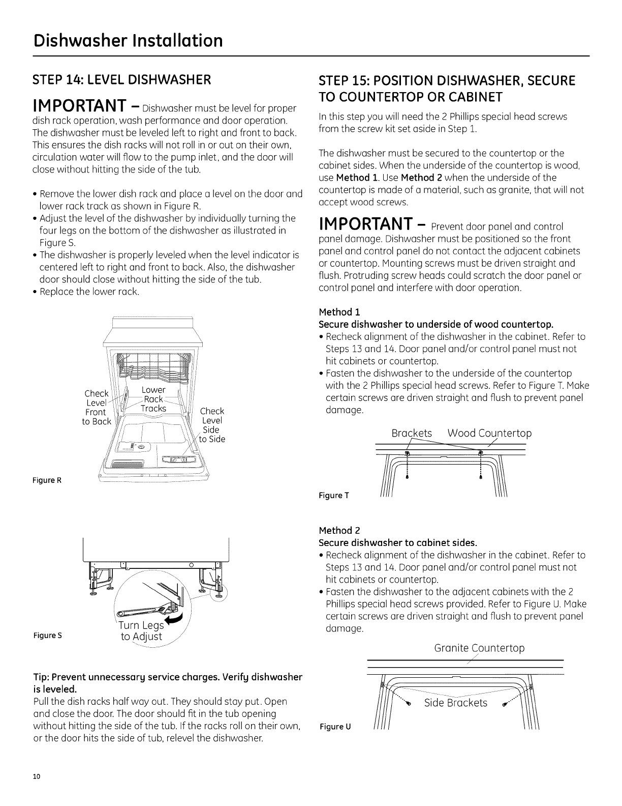
IM PORTANT - Beforeopeningthedishwasherdoor,
be certaintheedgesofthedishwasherdoorpanelarebehind
thefaceoftheadjacentcabinetand notup againstthecabinet
face.RefertoFigureQ.Ifthedishwasherdoorisopened
when theedge ofthedoorisagainstthefaceofthecabinet,
dishwasherdoordamage and cabinetdamage willoccur.
• Open and close the dishwasher door to be sure it operates
smoothly, and does not rub on the adjacent cabinet.
Door Door Catches
Fits and on Cabinet Frame
Swings
Back
Behind
Cabinet
Frame\
Correct
Alignment
Figure Q
Incorrect Alignment
will result indoor damage
Tip: Prevent unnecessarg service charges for panel damage
or wash performance.
Check dishwasher alignment prior to opening dishwasher door
to prevent panel damage.
Make sure utility lines are not trapped or crushed behind
dishwasher. Crushed lines will restrict water flow.
Dishwasher Installation
STEP 14: LEVEL DISHWASHER
IM PORTANT -Dishwashermust be levelforproper
dishrackoperation,wash performanceand dooroperation.
The dishwashermust be leveledlefttorightand fronttoback.
Thisensuresthedishrackswillnotrollinorouton theirown,
circulation water will flow to the pump inlet, and the door will
close without hittinc the side of the tub.
• Remove the lower dish rack and place a level on the door and
lower rack track as shown in Figure R.
• Adjust the level of the dishwasher by individually turning the
four legs on the bottom of the dishwasher as illustrated in
Figure S.
• The dishwasher is properly leveled when the level indicator is
centered left to right and front to back. Also,the dishwasher
door should close without hitting the side of the tub.
• Replace the lower rack.
Figure R
t
Check_
Front
to Back
Check
Level
Side
Side
/
STEP 15: POSITION DISHWASHER, SECURE
TO COUNTERTOP OR CABINET
In this step you will need the 2 Phillips special head screws
from the screw kit set aside in Step 1.
The dishwasher must be secured to the countertop or the
cabinet sides. When the underside of the countertop is wood,
use Method 1. Use Method 2 when the underside of the
countertop is made of a material, such as granite, that will not
accept wood screws.
IMPORTANT - Preventdoorpaneland control
paneldamage. Dishwashermust be positionedso thefront
paneland controlpaneldo notcontacttheadjacentcabinets
orcountertop.Mountingscrewsmust be drivenstraightand
flush.Protrudingscrewheadscouldscratchthedoorpanelor
controlpaneland interferewithdooroperation.
Method i
Secure dishwasher to underside of wood countertop.
• Recheck alignment of the dishwasher in the cabinet. Refer to
Steps 1:3and 1/4.Door panel and/or control panel must not
hit cabinets or countertop.
• Fasten the dishwasher to the underside of the countertop
with the 2 Phillips special head screws. Refer to Figure T.Make
certain screws are driven straight and flush to prevent panel
damage.
Figure T
Brackets Wood Countertop
Figure S
'Turn Legs
to Adjust j_
0
Tip: Prevent unnecessarg service charges. Verifg dishwasher
is leveled.
Pull the dish racks half way out. They should stay put. Open
and close the door. The door should fit in the tub opening
without hitting the side of the tub. If the racks roll on their own,
or the door hits the side of tub, relevel the dishwasher.
Method 2
Secure dishwasher to cabinet sides.
• Recheck alignment of the dishwasher in the cabinet. Refer to
Steps 13 and 14. Door panel and/or control panel must not
hit cabinets or countertop.
• Fasten the dishwasher to the adjacent cabinets with the 2
Phillips special head screws provided. Refer to Figure U.Make
certain screws are driven straight and flush to prevent panel
damage.
Granite Countertop
J
/
Figure U
% Side Braci<__ 1
lo
Dishwasher Installation
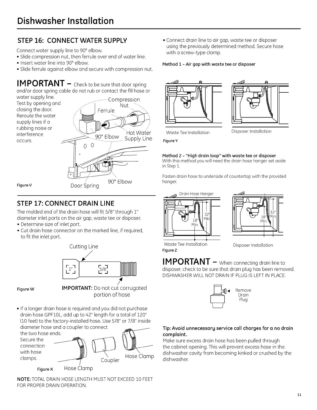
STEP 16: CONNECT WATER SUPPLY
Connect water supply line to 90 ° elbow.
• Slide compression nut, then ferrule over end of water line.
• Insert water line into 90° elbow.
• Slide ferrule against elbow and secure with compression nut.
Test by opening and
closing the door.
Reroute the water
supply lines if a
rubbing noise or
interference
Occurs.
IMPORTANT -Checktobe surethatdoorspring
and/ordoorspringcabledo notruborcontactthefillhose or
water supply line. ..................Compression
-- 90 ° Elbow Su_' Lne
_- ................ PPY
/90 ° Elbow
Figure V Door Spring
STEP 17: CONNECT DRAIN LINE
The molded end of the drain hose will fit 5/8" through 1"
diameter inlet ports on the air gap, waste tee or disposer.
• Determine size of inlet port.
• Cut drain hose connector on the marked line, if required,
to fit the inlet port.
Figure W
Cutting Line
,/
r,,-I r = lllllllllllll
,s/s;BuJJJJ.uw
#
IMPORTANT: Do not cut corrugated
portion of hose
• If a longer drain hose is required and you did not purchase
drain hose GPF10L,add up to 42" length for a total of 120"
(10 feet) to the factory-installed hose. Use 5/8" or 7/8" inside
diameter hose and a coupler to connect
the two hose ends.
Secure the
connection
with hose
clamps.
Figure × Hose Clamp
Coupler Hose Clamp
NOTE: TOTAL DRAIN HOSE LENGTH MUST NOT EXCEED 10 FEET
FOR PROPER DRAIN OPERATION.
• Connect drain line to air gap, waste tee or disposer
using the previously determined method. Secure hose
with a screw-type clamp.
Method 1 - Air gap with waste tee or disposer
Waste Tee Installation Disposer Installation
FigureY
Method 2 - "High drain loop" with waste tee or disposer
With this method you will need the drain hose hanger set aside
in Step 1.
Fasten drain hose to underside of countertop with the provided
hanger.
__ Drain Hose Hanger
32"
WasteTeeInstallation
Figure Z
Disposer Installation
IMPORTANT -When connectingdrainlineto
disposer,checktobe surethatdrainplughas been removed.
DISHWASHER WILL NOT DRAIN IFPLUG ISLEFTINPLACE.
4 Remove
Drain
Plug
Tip: Avoid unnecessarg service call charges for a no drain
complaint.
Make sure excess drain hose has been pulled through
the cabinet opening. This will prevent excess hose in the
dishwasher cavity from becoming kinked or crushed by the
dishwasher.
11
Dishwasher Installation
STEP 18: CONNECT POWER SUPPLY
Ifa power cord with plug is already installed proceed to
Step 19.
WARNING:
If housewiring is not 2-wirewith ground,o ground mustbe
providedby the installer.When housewiring isaluminum, besure
to use UL-Listedanti-oxidant compoundand aluminum-to-copper
connectors.
A ADVERTENCIA:
Sielcableadodom_sticonocuentacon uncablede2 hiloscon
conexi6na tierra,uninstaladordeberealizarunaconexi6na tierra.
Cuandoelcableadodom_sticoesdealuminio,aseg0resedeusar
uncompuestoantioxidanteyconectoresdealuminioacobre
aprobadosparUL.
In this step you will need the junction box cover and the
#10 Hex head screw from the screw kit set aside in Step 1.
STEP 19: PRETEST CHECKLIST
Review this list after installing your dishwasher to avoid
charges for a service call that is not covered by your
warranty.
[] Check to be sure power is OFF.
[]
[]
[]
[]
[]
[]
[]
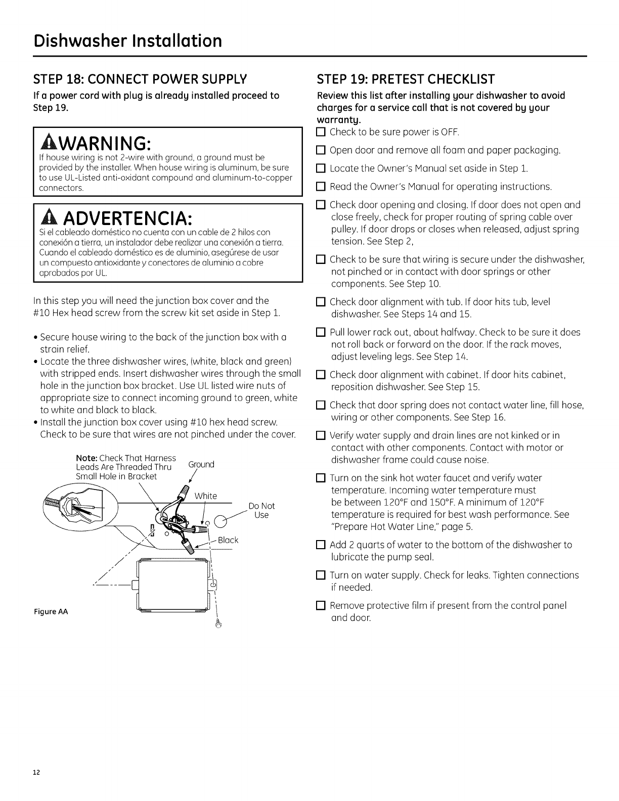
• Secure house wiring to the buck of the junction box with o
strain relief.
• Locate the three dishwasher wires, (white, black and green)
with stripped ends. Insert dishwasher wires through the small []
hole in the junction box bracket. Use UL listed wire nuts of
appropriate sizeto connect incoming ground to green, white
to white and black to black. []
• Install the junction box cover using #10 hex head screw.
Check to be sure that wires are not pinched under the cover. []
Do Not
Use
Note: Check That Harness
LeadsAreThreadedThru Ground_
SmallHolein Bracket _/
___"_ X ._Whit e
Open door and remove all foam and paper packaging.
Locate the Owner's Manual set aside in Step 1.
Read the Owner's Manual for operating instructions.
Check door opening and closing. If door does not open and
close freely, check for proper routing of spring cable over
pulley. If door drops or closes when released, adjust spring
tension. See Step 2,
Check to be sure that wiring is secure under the dishwasher,
not pinched or in contact with door springs or other
components. See Step 10.
Check door alignment with tub. If door hits tub, level
dishwasher. SeeSteps 14 and 15.
Pull lower rack out, about halfway. Check to be sure it does
not roll back or forward on the door. If the rack moves,
adjust leveling legs. See Step 14.
Check door alignment with cabinet. If door hits cabinet,
reposition dishwasher. SeeStep 15.
Check that door spring does not contact water line, fill hose,
wiring or other components. See Step 16.
Verify water supply and drain lines are not kinked or in
contact with other components. Contact with motor or
dishwasher frame could cause noise.
[]
[]
[]
Turn on the sink hot water faucet and verify water
temperature. Incoming water temperature must
be between 120°F and 150°F.A minimum of 120°F
temperature is required for best wash performance. See
"Prepare Hot Water Line,"page 5.
Add 2 quarts of water to the bottom of the dishwasher to
lubricate the pump seal.
Turn on water supply. Check for leaks. Tighten connections
if needed.
[] Remove protective film if present from the control panel
and door.
12
Dishwasher Installation
STEP 20: DISHWASHER WET TEST
[] Turn on power supply or plug power cord into outlet,
if equipped.
[] Latch door.
[] Push Rinse Only pad/button.
[] Push Start/Reset pad/button one time. Dishwasher should
start.
[] Check to be sure that water enters the dishwasher. If water
does not enter the dishwasher, check to be sure that water
and power are turned on.
[] Check for leaks under the dishwasher. If a leak is found,
turn off power at the breaker, and then tighten water
connections. Restore power after leak is corrected.
[] Check for leaks around the door. A leak around the door
could be caused by door rubbing or hitting against
adjacent cabinets. Reposition the dishwasher if necessary.
SeeStep 15.
[] The dishwasher will drain and turn off about 5 minutes after
it was started. Check drain lines. If leaks are found, turn off
power at the breaker and correct plumbing as necessary.
Restore power after corrections are made. SeeSteps 7
and 17.
[] Open dishwasher door and make sure most of the water
has drained. If not, check that disposer plug has been
removed and/or air gap is not plugged. Also check drain
hose to be sure it is not kinked underneath or behind
dishwasher. See Step 17.
[] PressStart/Reset pad/button once again and run
dishwasher through another "Rinse Only" cycle. Check for
leaks and correct if required.
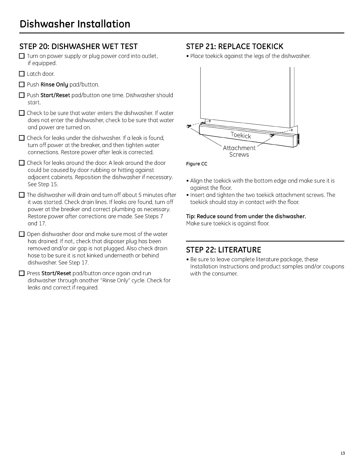
STEP 21: REPLACE TOEKICK
• Place toekick against the legs of the dishwasher.
Figure CC
Screws
• Align the toekick with the bottom edge and make sure it is
against the floor.
• Insert and tighten the two toekick attachment screws. The
toekick should stay in contact with the floor.
Tip: Reduce sound from under the dishwasher.
Hake sure toekick is against floor.
STEP 22: LITERATURE
• Be sure to leave complete literature package, these
Installation Instructions and product samples and/or coupons
with the consumer.
13

Notes
14

Notes
13

SPECIFICATIONS SUBJECT TO CHANGE WITHOUT NOTICE
GEAppliances & Lighting
General Electric Company
Louisville, Kentucky 40225
GEAppliances.com
© 2011 General Electric Company
