GE GXSH40V00 User Manual WATER SOFTENER Manuals And Guides 1206467L
User Manual: GE GXSH40V00 GXSH40V00 GE WATER SOFTENER - Manuals and Guides View the owners manual for your GE WATER SOFTENER #GXSH40V00. Home:Plumbing Parts:GE Parts:GE WATER SOFTENER Manual
Open the PDF directly: View PDF ![]() .
.
Page Count: 80
GEAppliances.com
om
0
(./3
U3
g3
Safety Information .................... 2
Specifications and Dimensions ........ 3
About the Softener .................... 6
Before you Start ....................... 7
Installation Requirements .......... 8-10
Installation Instructions ........... 11-15
Programming the Softener ........ 16-21
Care and Cleaning ................. 22, 23
Routine Maintenance ................. 24
Before you call for Service ......... 25-28
Exploded ViewlParts List .......... 31-34
Warranty (U.S.)....................... 35
Warranty (Canada) ................... 36
Water Softening
System
Models GXSH4OV,GXSH45V
Write the model ond seriol
numbers here:
Model #
Seriol #
To find these numbers, lift
the cover and look on the rim
below the control panel.
Systems tested and certified by NSFInternational against
NSF/ANS!Standard 44 for the chemical reduction claims
specified on page 3.
Systems Tested and Certified by the Water Quality Association
against CSAB483.1.
If you have any questions or concerns when installing or maintaining your
water softener, call our toll free number at 800-952-5039 (US)or 866-777-7627
(Canada}, or visit www.geappliances.com When you call, please be prepared
to provide the model and serial number of your product. This information can
befound on the rating decal located on the rim under the salt cover.
7329201 49-50283-1 01-12GE
IMPORTANT SAFETY INFORMATION.
READ ALL INSTRUCTIONS BEFORE USING.
SAFETYPRECAUTIONS
_k WARNING! Foryoursdety,theinformationinthismanualmustbe_ollo_edtominimize
the risk of electric shock, property damage or personal injury.
&DANGER:
Electric Shock Hazard:
Install metal ground clamp to metal house
water supply pipe before beginning
installation. Securely tighten connection in
center of metal ground clamp. Failure to do
so can result in death or electric shock.
Check and comply with your state and local
codes. You must follow these guidelines.
_: Use care when handling the water softening
system. Do not turn upside down, drop, drag or
set on sharp protrusions.
Water softening systems using sodium chloride
(salt)for recharge add sodium to the water.
Persons on sodium restricted diets should
consider the added sodium as part of their
overall intake. Potassium chloride can be used
as an alternative to sodium chloride in your
softener.
Use only lead-free solder and flux for all sweat-
solder connections, as required by state and
federal codes.
This water softening system must be properly
installed and located in accordance with the
installation instructions before it is used.
AWAR NING:oonot use with water
that is microbiologically unsafe or of unknown
quality without adequate disinfection before
or after the system.
WARNING: Discard all unused
parts and packaging material after
installation. Small parts remaining after the
installation could be a choke hazard.
iiiiiii_
iiiiiii_
The water softening system works on 2/4volt-
60 Hz electrical power only. Be sure to use the
included external power supply.
External power supply must be plugged into an
indoor 120 volt, grounded outlet only.
Use clean water softening salts only, at least
99.5% pure. NUGGET,PELLETor coarse SOLAR
salts are recommended. Do not use rock, block,
granulated or ice cream making salts. They
contain dirt and sediments, or mush and cake,
and will create maintenance problems.
Keep the salt hole cover in place on the softener
unless servicing the unit or refilling with salt.
In the state of California: You must turn the
Salt Efficiency Feature setting to ON. This may
initiate more frequent recharges. However it
will operate at 4,000 grains per pound of salt or
higher. To turn on the Salt Efficiency Feature,
follow the instructions in the "Salt Saver"
section of this manual
In the Commonwealth of Massachusetts,
Plumbing Code 248 CMR shall be adhered to.
Consult with your licensed plumber.
_'1__ _ READ AND FOLLOW THI_ _FET_ INFORMATION C_REFULL_.
/_F-_ SAVE THESE INSTRUCTIONS
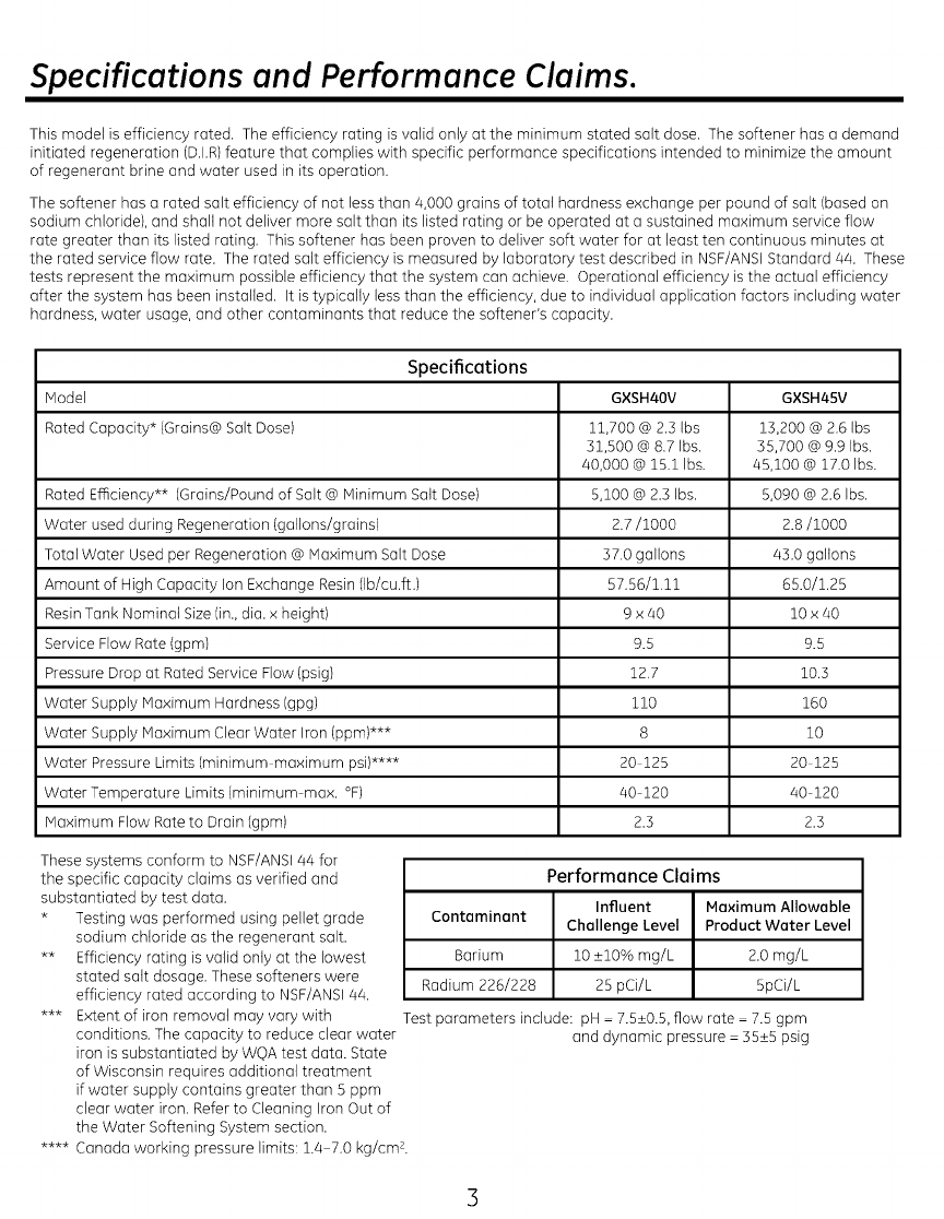
Specifications and Performance Claims.
This model is efficiency rated, The efficiency rating is valid only at the minimum stated salt dose, The softener has a demand
initiated regeneration (D,I,R)feature that complies with specific performance specifications intended to minimize the amount
of regenerant brine and water used in its operation.
The softener has a rated salt efficiency of not less than 4,000 grains of total hardness exchange per pound of salt (based on
sodium chloride), and shall not deliver more salt than its listed rating or be operated at a sustained maximum service flow
rate greater than its listed rating, This softener has been proven to deliver soft water for at least ten continuous minutes at
the rated service flow rate. The rated salt efficiency is measured by laboratory test described in NSF/ANSI Standard/44. These
tests represent the maximum possible efficiency that the system can achieve, Operational efficiency is the actual efficiency
after the system has been installed, It is typically less than the efficiency, due to individual application factors including water
hardness, water usage, and other contaminants that reduce the softener's capacity.
Model
Rated Capacity* (Grains@ Salt Dose)
Specifications
Rated Efficiency** (Grains/Pound of Salt @ Minimum Salt Dose)
Water used during Regeneration (gallons/grains)
Total Water Used per Regeneration @ Maximum Salt Dose
Amount of High Capacity Ion Exchange Resin (Ib/cu,ft,)
Resin Tank Nominal Size (in., dia. x height)
Service Flow Rate (gpm)
Pressure Drop at Rated Service Flow (psig)
Water Supply Maximum Hardness (gpg)
Water Supply Maximum Clear Water Iron (ppm)***
Water Pressure Limits (minimum maximum psi)****
Water Temperature Limits (minimum max. °F)
Maximum Flow Rate to Drain (gpm)
GXSH40V
11,700 @ 2,3 Ibs
31,500 @ 8.7 Ibs,
40,000 @ 15,1 Ibs.
5,100 @ 2.3 Ibs.
2.7/1000
37,0 gallons
57,56/i,ii
9Ha0
9.5
12,7
110
8
20 125
40 120
2.3
GXSH45V
13,200 @2,6 Ibs
55,700 @ 9,9 Ibs,
45,100 @ 17,0 Ibs.
5,090 @ 2.6 Ibs,
2.8/1000
43,0 gallons
65.0/125
10 x 40
9.5
10S
160
10
20 125
40 120
2.3
These systems conform to NSF/ANSI 44 for
the specific capacity claims as verified and
substantiated by test data.
* Testing was performed using pellet grade
sodium chloride as the regenerant salt.
** Efficiency rating is valid only at the lowest
stated salt dosage, These softeners were
efficiency rated according to NSF/ANSI 44,
*** Extent of iron removal may vary with
conditions. The capacity to reduce clear water
iron is substantiated by WOA test data. State
of Wisconsin requires additional treatment
if water supply contains greater than S ppm
clear water iron. Refer to Cleaning Iron Out of
the Water Softening System section.
.... Canada working pressure limits: 1.a 7.o kg/cm%
Performance Claims
Influent Maximum Allowable
Contaminant Challenge Level Product Water Level
Barium 10 _+10% mg/L 2.0 mg/L
Radium 226/228 25 pCi/L SpCi/L
Test parameters include: pH - 7.5_+0.5,flow rate - 7.5 gpm
and dynamic pressure - 55_+5 psig
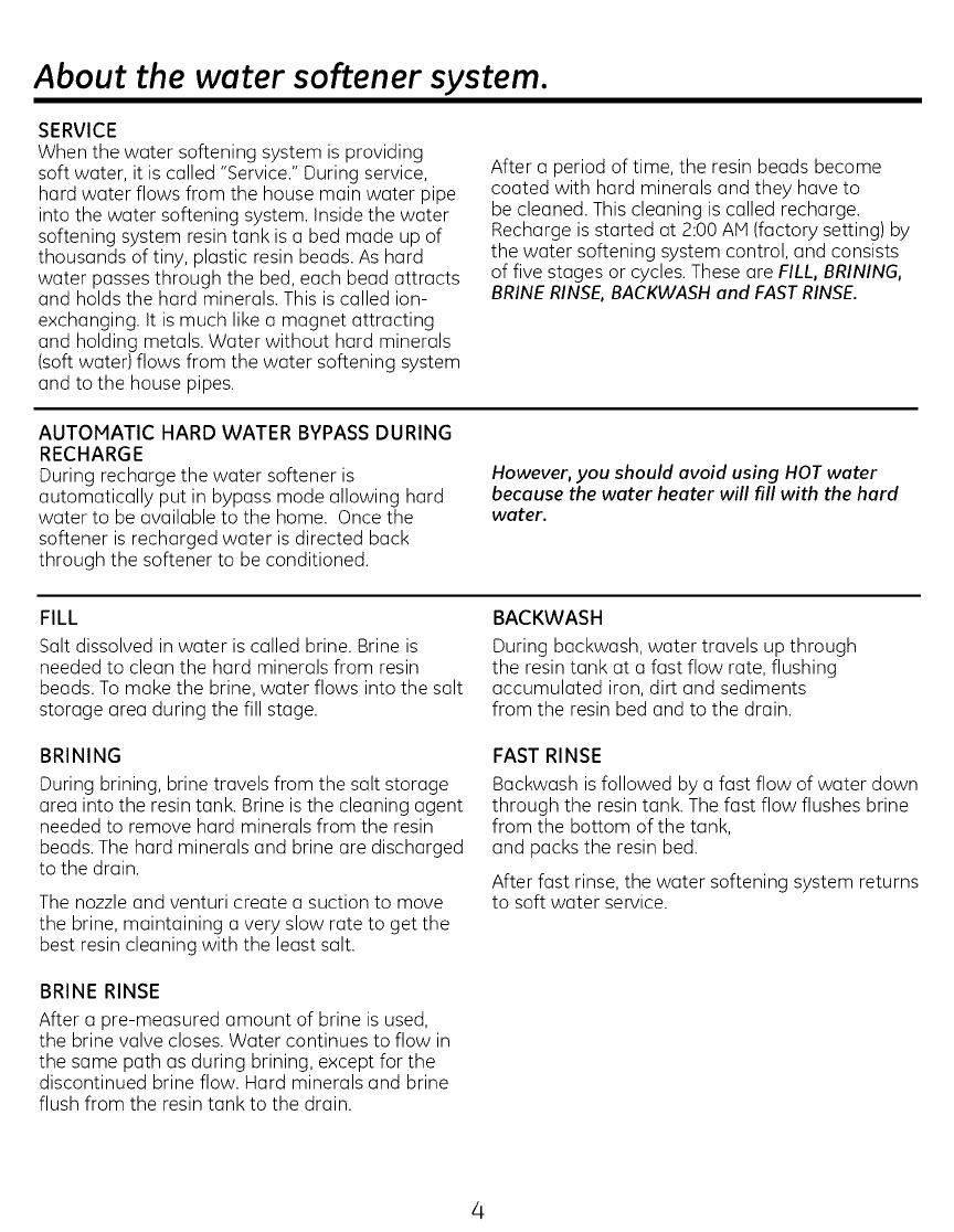
About the water softener system.
SERVICE
When the water softening system is providing
soft water, it is called "Service." During service,
hard water flows from the house main water pipe
into the water softening system. Inside the water
softening system resin tank is a bed made up of
thousands of tiny, plastic resin beads. As hard
water passes through the bed, each bead attracts
and holds the hard minerals. This is called ion-
exchanging. It is much like a magnet attracting
and holding metals. Water without hard minerals
(soft water) flows from the water softening system
and to the house pipes.
After a period of time, the resin beads become
coated with hard minerals and they have to
be cleaned. This cleaning is called recharge.
Recharge is started at 2:00 AM (factory setting) by
the water softening system control, and consists
of five stages or cycles. These are FILL, BRINING,
BRINE RINSE, BACKWASH and FASTRINSE.
AUTOMATIC HARD WATER BYPASS DURING
RECHARGE
During recharge the water softener is
automatically put in bypass mode allowing hard
water to be available to the home. Once the
softener is recharged water is directed back
through the softener to be conditioned.
However, you should avoid using HOT water
because the water heater will fill with the hard
water.
FILL
Salt dissolved in water is called brine. Brine is
needed to clean the hard minerals from resin
beads. To make the brine, water flows into the salt
storage area during the fill stage.
BRINING
During brining, brine travels from the salt storage
area into the resin tank. Brine is the cleaning agent
needed to remove hard minerals from the resin
beads. The hard minerals and brine are discharged
to the drain.
The nozzle and venturi create a suction to move
the brine, maintaining a very slow rate to get the
best resin cleaning with the least salt.
BRINE RINSE
After a pre-measured amount of brine is used,
the brine valve closes. Water continues to flow in
the same path as during brining, except for the
discontinued brine flow. Hard minerals and brine
flush from the resin tank to the drain.
BACKWASH
During backwash, water travels up through
the resin tank at a fast flow rate, flushing
accumulated iron, dirt and sediments
from the resin bed and to the drain.
FAST RINSE
Backwash is followed by a fast flow of water down
through the resin tank. The fast flow flushes brine
from the bottom of the tank,
and packs the resin bed.
After fast rinse, the water softening system returns
to soft water service.
About the water softener system.
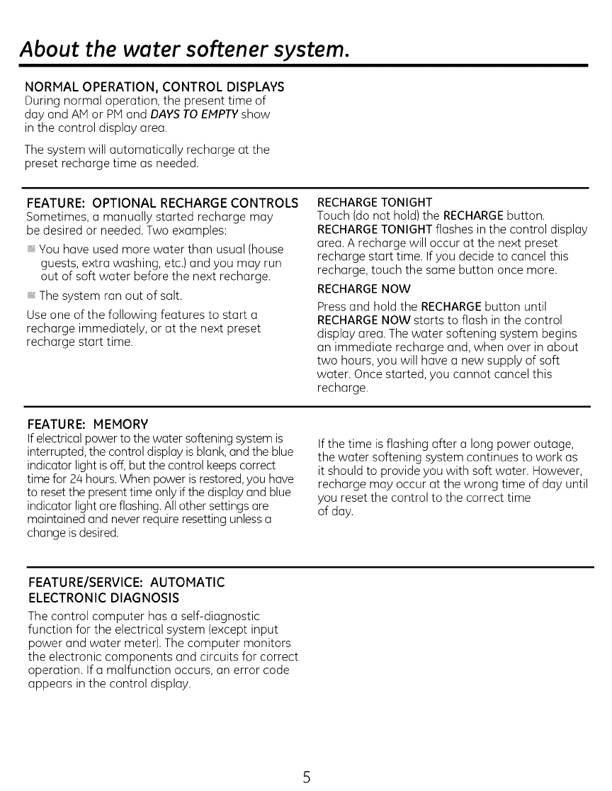
NORMAL OPERATION, CONTROL DISPLAYS
During normal operation, the present time of
day and AM or PM and DAYS TO EMPTYshow
in the control display area.
The system will automatically recharge at the
preset recharge time as needed.
FEATURE: OPTIONAL RECHARGE CONTROLS
Sometimes, a manually started recharge may
be desired or needed. Two examples:
You have used more water than usual (house
guests, extra washing, etc.) and you may run
out of soft water before the next recharge.
The system ran out of salt.
Use one of the following features to start a
recharge immediately, or at the next preset
recharge start time.
RECHARGE TONIGHT
Touch (do not hold) the RECHARGE button.
RECHARGE TONIGHT flashes in the control display
area. A recharge will occur at the next preset
recharge start time. If you decide to cancel this
recharge, touch the same button once more.
RECHARGE NOW
Press and hold the RECHARGE button until
RECHARGE NOW starts to flash in the control
display area. The water softening system begins
an immediate recharge and, when over in about
two hours, you will have a new supply of soft
water. Once started, you cannot cancel this
recharge.
FEATURE: MEMORY
If electrical power to the water softening system is
interrupted, the control display is blank, and the blue
indicator light is off, but the control keeps correct
time for 24 hours. When power is restored, you have
to reset the present time only if the display and blue
indicator light are flashing. All other settings are
maintained and never require resetting unless a
change is desired.
If the time is flashing after a long power outage,
the water softening system continues to work as
it should to provide you with soft water. However,
recharge may occur at the wrong time of day until
you reset the control to the correct time
of day.
FEATURE/SERVICE: AUTOMATIC
ELECTRONIC DIAGNOSIS
The control computer has a self-diagnostic
function for the electrical system (except input
power and water meter). The computer monitors
the electronic components and circuits for correct
operation. If a malfunction occurs, an error code
appears in the control display.
About the water softener system.
WATER CONDITION INFORMATION
IRON
Iron in water can cause stains on clothing and
plumbing fixtures. It can negatively affect the
taste of food,drinking water, and other beverages.
Iron in water is measured in parts per million
(ppm). The total* ppm of iron, and type or types*,
is determined by chemical analysis. Four different
types of iron in water are:
Ferrous (clear water)iron
Ferric (red water)iron
Bacterial and organically bound iron
Colloidal and inorganically bound iron (ferrous
or ferric)
Ferrous (clear water)iron is soluble and dissolves
in water. This water softener will reduce
moderate amounts of this type of iron (see
specifications).**Ferrous (clear water)iron is
usually detected by taking a sample of water in
a clear bottle or glass. Immediately after taking,
the sample is clear. As the water sample stands,
it gradually clouds and turns slightly yellow or
brown as air oxidizes the iron. This usually occurs
in 15 to 30 minutes.
When using the softener to reduce Ferrous (clear
water) iron, add 5 grains to the hardness setting
fore very 1 ppm of Ferrous (clear water)iron. See
"Set Water Hardness Number" section.
Ferric (red water), and bacterial and organically
bound irons are insoluble. This water softener
will not remove ferric or bacterial iron. This iron
is visible immediately when drawn from a faucet
because it has oxidized before reaching the
home. It appears as small cloudy yellow, orange,
or reddish suspended particles. After the water
stands for a period of time,the particles settle to
the bottom of the container. Generally these irons
are removed from water by filtration. Chlorination
is also recommended for bacterial iron.
Colloidal and inorganically bound iron is of ferric
or ferrous form that will not filter or exchange
out of water. This water softener will not remove
colloidal iron. In some instances, treatment
may improve colloidal iron water. Colloidal iron
water usually has a yellow appearance when
drawn. After standing for several hours, the color
persists and the iron does not settle, but remains
suspended in the water.
SEDIMENT
Sediment is fine, foreign material particles
suspended in water. This water softener will not
remove sediment. This material is most often clay
or silt. Extreme amounts of sediment may give
the water a cloudy appearance. A sediment filter
installed upstream of the water softener normally
corrects this situation.
* Water may contain one or more of the four
types of iron and any combination of these. Total
iron is the sum of the contents.
** Capacity to reduce clear water iron is
substantiated by WOA test data.
CHLORINE
Softener resins may degrade in the presence
of chlorine above 2 ppm. If you have chlorine
in excess of this amount, you may experience
reduced life of the resin. In these conditions, you
may wish to consider purchasing a GE point-of-
entry household filtration system with a chlorine
reducing filter.
Before you start.
BEFORE YOU START
The water softener requires a minimum water flow of 3 gallons per minute at the inlet. Maximum
allowable inlet water pressure is 125 psi. If daytime pressure is over 80 psi, nighttime pressure may
exceed the maximum. Use a pressure reducing valve if necessary (Adding o pressure reducing valve
may reduce the flow). If your home is equipped with a back flow preventer, on expansion tank must
be installed in accordance with local codes and lows.
The water softener uses o direct plug-in external power supply (included). Be sure to use the included
power supply and plug it into o nominal 120V, 60 cycle household outlet that is in o dry location only,
grounded and properly protected by an over current device such as o circuit breaker or fuse.
Do not use this system to treat water that is microbiologicully unsafe or of unknown quality without
adequate disinfection upstream or downstream of the system.
TOOLS AND MATERIALS REQUIRED FOR INSTALLATION
Razor knifePliers
Screwdriver
Teflon tape
Two adjustable wrenches
Additional tools may be required if modification
to home plumbing is necessary.
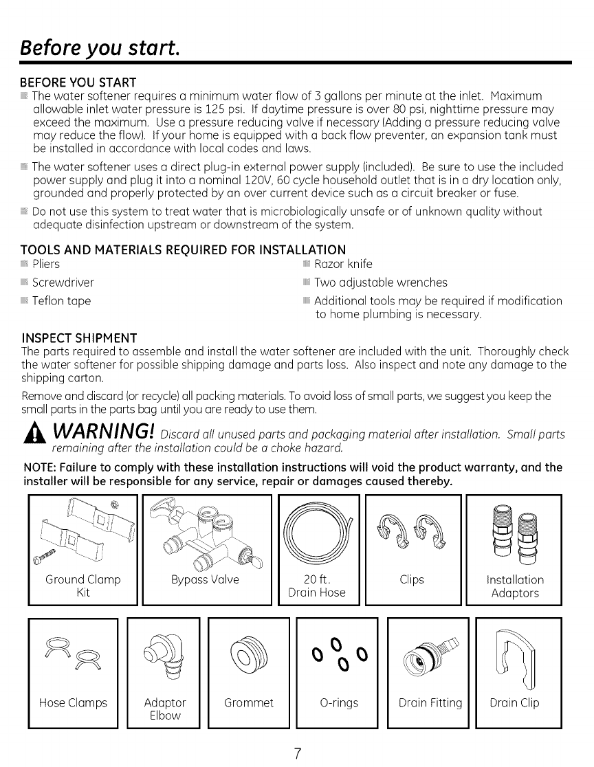
INSPECT SHIPMENT
The ports required to assemble and install the water softener ore included with the unit. Thoroughly check
the water softener for possible shipping damage and ports loss. Also inspect and note any damage to the
shipping carton.
Removeand discord (or recycle)all packing materials. Toovoid loss of small ports, we suggest you keep the
small ports in the ports bug until you are ready to use them.
WARNING! Discord oil unused ports ond pockoging material after installation. Small ports
remaining after the installation could be o choke hazard.
NOTE: Failure to comply with these installation instructions will void the product warranty, and the
Ground Clamp
Kit
installer will be responsible for any service, re _air or damages caused thereby.
20 ft. Clips
Drain Hose
Bypass Valve Installation
Adaptors
Hose Clamps Adaptor
Elbow Grommet O-rings Drain Fitting Drain Clip
Installation Requirements.
LOCATION REQUIREMENTS
Consider all of the following when selecting an
installation location for the water softener.
Do not locate the water softener where freezing
temperatures occur. Do not attempt to treat
water over 120°F. Freezing temperatures or
hot water damage voids the warranty.
To condition all water in the home, install
the water softener close to the water supply
inlet, and upstream of all other plumbing
connections, except outside water pipes.
Outside faucets should remain on hard water to
avoid wasting conditioned water and salt.
A nearby drain is needed to carry away
regeneration discharge (drain) water. Use a
floor drain,laundry tub, sump, standpipe, or
other options(check your local codes). See
"Air Gap Requirements" and "Valve Drain
Requirements"sections.
The water softener uses a direct plug-in
external power supply (included). Besure to
use the included power supply and plug it into
a nominal 120V, 60 cycle household outlet that
is in a dry location only, grounded and properly
protected by an over current device such as a
circuit breaker or fuse.
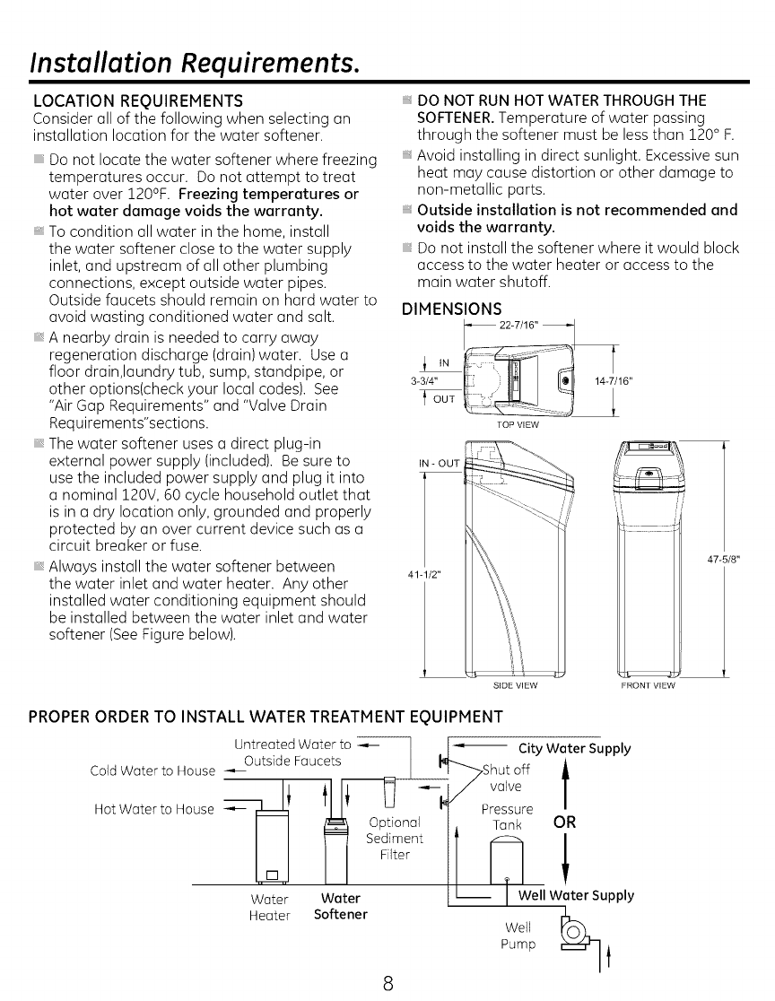
Always install the water softener between
the water inlet and water heater. Any other
installed water conditioning equipment should
be installed between the water inlet and water
softener (SeeFigure below).
DO NOT RUN HOT WATER THROUGH THE
SOFTENER. Temperature of water passing
through the softener must be less than 120 ° F.
Avoid installing in direct sunlight. Excessive sun
heat may cause distortion or other damage to
non-metallic parts.
Outside installation is not recommended and
voids the warranty.
Do not install the softener where it would block
access to the water heater or access to the
main water shutoff.
DIMENSIONS
_ 22-7/16"
3-3/4" _{t: IIMI IL° I 14-7/16"
TOP VIEW
IN - OUT
47-5/8"
41-1/2"
SIDE VIEW FRONT VIEW
PROPER ORDER TO INSTALL WATER TREATMENT EQUIPMENT
UntreatedWater to --.-- I . I_'_ City Water Supply
.,_Outside Faucets_l_shut off i
ColdWater to House _ "--I_ valve
/_ Optional I, Tank OR
I I _=I Sediment If _I
Wo_er ;aJer Filter U I !ell 2ter Supply
Heater Softener PumpWell _
8
Installation Requirements.
PLUMBING CODES
All plumbing must be completed in accordance
with national, state and local plumbing codes.
In the state of Massachusetts: TheCommonwealth
of Massachusetts plumbing code 2¢8-CMR shall be
adhered to. A licensed plumber shall be used for
this installation.
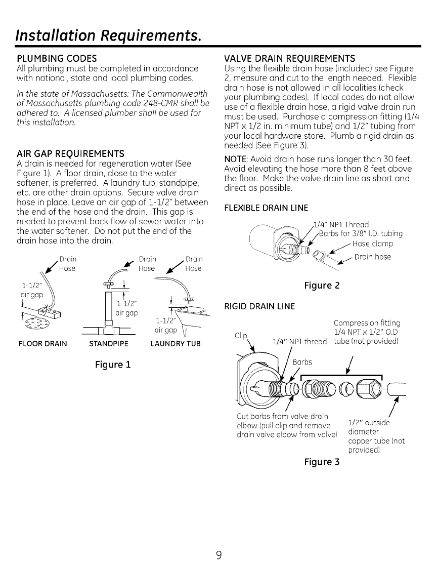
AIR GAP REQUIREMENTS
A drain is needed for regeneration water (See
Figure 1). A floor drain, close to the water
softener, is preferred. A laundry tub, standpipe,
etc. are other drain options. Secure valve drain
hose in place. Leave an air gap of 1-1/2" between
the end of the hose and the drain. This gap is
needed to prevent back flow of sewer water into
the water softener. Do not put the end of the
drain hose into the drain.
Drain
11/2"_ Hose
FLOOR DRAIN
Hose /Drain
Drain ,_/ Hose
M air
__. I_ airgap \l
STANDPIPE LAUNDRY TUB
Figure 1
VALVE DRAIN REQUIREMENTS
Using the flexible drain hose (included) see Figure
2, measure and cut to the length needed. Flexible
drain hose is not allowed in all localities (check
your plumbing codes). )f local codes do not allow
use of a flexible drain hose, a rigid valve drain run
must be used. Purchase a compression fitting (1//4
NPTx 1/2 in. minimum tube) and 1/2" tubing from
your local hardware store. Plumb a rigid drain as
needed (SeeFigure 3).
NOTE:Avoid drain hose runs longer than 30 feet.
Avoid elevating the hose more than 8 feet above
the floor. Make the valve drain line as short and
direct as possible.
FLEXIBLE DRAIN LINE
NPTThread
,Barbsfor 3/8" I.D.tubing
clamp
hose
Figure 2
RIGID DRAIN LINE
Compressionfitting
Cli- 1//4 NPT× 1/2" O.D
_u_\. l/a," NPTthread tube (notprovided)
B_lrbs
Cutbarbsfrom valvedrain
elbow(pullclipand remove 1/2" outside
drain valve elbowfrom valve) diameter
coppertube (not
provided)
Figure 3
Installation Requirements.
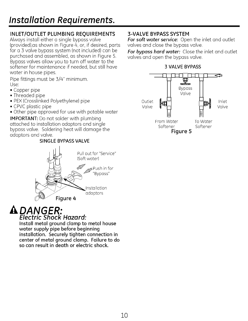
INLET/OUTLET PLUMBING REQUIREMENTS
Always install either a single bypass valve
(provided),as shown in Figure 4, or, if desired, parts
for a 3 valve bypass system (not included) can be
purchased and assembled, as shown in Figure 5.
Bypass valves allow you to turn off water to the
softener for maintenance if needed, but still have
water in house pipes.
Pipe fittings must be 3/4" minimum.
Use:
• Copper pipe
• Threaded pipe
• PEX(Crosslinked Polyethylene) pipe
• CPVCplastic pipe
• Other pipe approved for use with potable water
IMPORTANT: Do not solder with plumbing
attached to installation adaptors and single
bypass valve. Soldering heat will damage the
adaptors and valve.
SINGLEBYPASSVALVE
3-VALVE BYPASS SYSTEM
For soft water service: Open the inlet and outlet
valves and close the bypass valve.
For bypass hard water: Close the inlet and outlet
valves and open the bypass valve.
3 VALVE BYPASS
Outlet
Valve
let
alve
FromWater ToWater
Softener Softener
Figure 5
Pullout for "Service"
(Softwater)
Ca 2s!°r
Installation
adaptors
Figure 4
DANGER:
Electric Shock Hazard:
Install metal ground clamp to metal house
water supply pipe before beginning
installation. Securely tighten connection in
center of metal ground clamp. Failure to do
so can result in death or electric shock.
10
Installation Instructions.
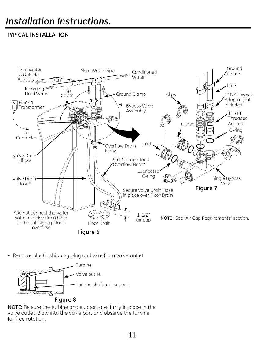
TYPICAL INSTALLATION
Hard Water
to Outside
Faucets
Incoming- _
Hard Water
_ Plug-in
Transformer
/I
\k
To
Controller
Elbow
Valve
Hose*
Top
Cc
Main Water Pipe Conditioned
Water
Ground Clamp Clip.s
)ass Valve
Assembly
)verflow Drain InJet _,_£q
Elbow ._/_
Salt Storage Tank "-_¢L(.__(_
H°Lue;ricatedJ
O-ring _"
Secure Valve Drain Hose
in place over Floor Drain
Ground
Clamp
1/Pipe
2" NPTSweat
JAdaptor (not
t_included)
l" NPT
Threaded
Adaptor
O-ring
)ass
Valve
Figure 7
*Do not connect the water 1-1/2"
softener valve drain hose
to the salt storage tank Floor Drain air gap
overflow Figure 6
NOTE: See "Air Gap Requirements" section.
•Remove plastic shipping plug and wire from valve outlet.
_-_2_j_ Turbine
Valve outlet
_ Turbine shaft and support
Figure 8
NOTE: Be sure the turbine and support are firmly in place in the
valve outlet. Blow into the valve port and observe the turbine
for free rotation.
11
Installation Instructions.
TURN OFF WATER SUPPLY
1. Close the main water supply valve, located near
the well pump or water meter. Salt
2. Open all faucets to drain all water from house
pipes.
NOTE: Be sure not to drain water from the water
heater, as damage to the water heater elements Brinewell
could result.
Jri
Assembly
Ferrule
Hole
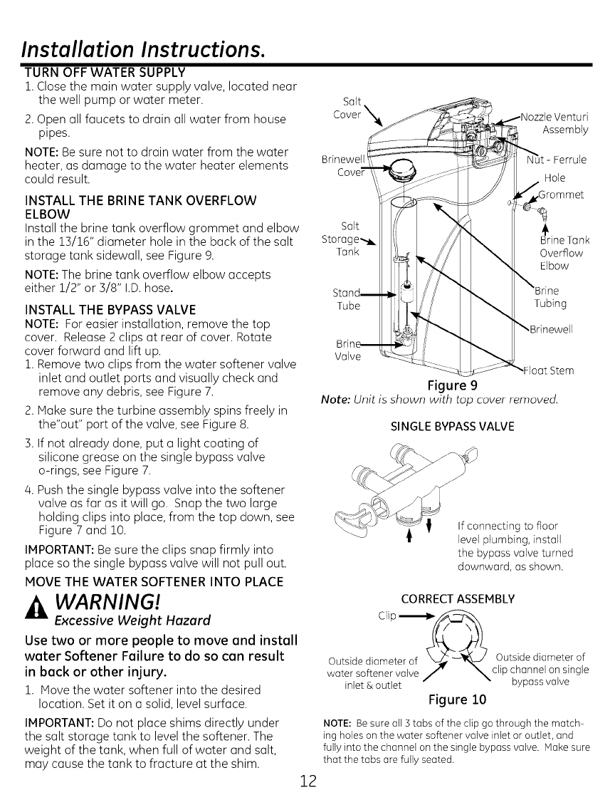
INSTALL THE BRINE TANK OVERFLOW
ELBOW
Install the brine tank overflow grommet and elbow
in the 13/16" diameter hole in the back of the salt
storage tank sidewall, see Figure 9.
NOTE: The brine tank overflow elbow accepts
either 1/2" or 3/8" !.D.hose.
INSTALL THE BYPASS VALVE
NOTE: For easier installation, remove the top
cover. Release 2 clips at rear of cover. Rotate
cover forward and lift up.
1. Remove two clips from the water softener valve
inlet and outlet ports and visually check and
remove any debris, see Figure 7.
2. Hake sure the turbine assembly spins freely in
the"out" port of the valve, see Figure 8.
3. If not already done, put a light coating of
silicone grease on the single bypass valve
o-rings, see Figure 7.
4. Push the single bypass valve into the softener
valve as far as it will go. Snap the two large
holding clips into place, from the top down, see
Figure 7 and 10.
IMPORTANT: Be sure the clips snap firmly into
place so the single bypass valve will not pull out.
HOVE THE WATER SOFTENER INTO PLACE
WARNING!
Excessive Weight Hazard
Use two or more people to move end install
weter Softener Feilure to do so con result
in beck or other injury.
1. Hove the water softener into the desired
location. Set it on a solid, level surface.
IMPORTANT: Do not place shims directly under
the salt storage tank to level the softener. The
weight of the tank, when full of water and salt,
may cause the tank to fracture at the shim.
12
Salt
Storage-,_ B_rineTank
Tank Overflow
Elbow
Tube Tubing
Valve
Stem
Figure 9
Note: Unit is shown with top cover removed.
SINGLE BYPASS VALVE
If connecting to floor
level plumbing, install
the bypass valve turned
downward, as shown.
CORRECT ASSEMBLY
Outside diameter of _ --_,,_ Outside diameter of
water softener valve J _clip channel on single
inlet & outlet bypass valve
Figure 10
NOTE: Be sure all 3 tabs of the clip go through the match
ing holes on the water softener valve inlet or outlet, and
fully into the channel on the single bypass valve. Hake sure
that the tabs are fully seated.
Installation Instructions.
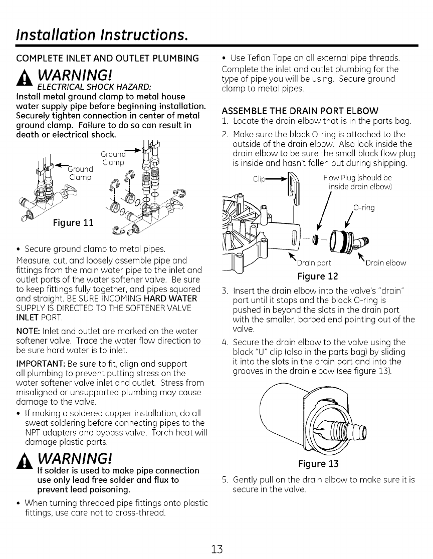
COMPLETE INLET AND OUTLET PLUMBING
WARNING!
ELECTRICALSHOCK HAZARD:
Install metal ground clamp to metal house
water supply pipe before beginning installation.
Securely tighten connection in center of metal
ground clamp. Failure to do so can result in
death or electrical shock.
Gr°un !
I_I_G round Clamp
• Secure ground clamp to metal pipes.
Measure, cut, and loosely assemble pipe and
fittings from the main water pipe to the inlet and
outlet ports of the water softener valve. Be sure
to keep fittings fully together, and pipes squared
and straight. BE SUREINCOMING HARD WATER
SUPPLYIS DIRECTEDTO THESOFTENERVALVE
INLET PORT.
NOTE: Inlet and outlet are marked on the water
softener valve. Trace the water flow direction to
be sure hard water is to inlet.
IMPORTANT: Be sure to fit, align and support
all plumbing to prevent putting stress on the
water softener valve inlet and outlet. Stress from
misaligned or unsupported plumbing may cause
damage to the valve.
• If making a soldered copper installation, do all
sweat soldering before connecting pipes to the
NPTadapters and bypass valve. Torch heat will
damage plastic parts.
WARNING!
If solder is used to make pipe connection
use only lead free solder and flux to
prevent lead poisoning.
• When turning threaded pipe fittings onto plastic
fittings, use care not to cross-thread.
• Use Teflon Tape on all external pipe threads.
Complete the inlet and outlet plumbing for the
type of pipe you will be using. Secure ground
clamp to metal pipes.
ASSEMBLE THE DRAIN PORT ELBOW
1. Locate the drain elbow that is in the parts bag.
2. Make sure the black O-ring is attached to the
outside of the drain elbow. Also look inside the
drain elbow to be sure the small black flow plug
is inside and hasn't fallen out during shipping.
CI Flow Plug (should be
inside drain elbow)
O-ring
/
_"Di[-in por_Drain elbow
Figure 12
3. Insert the drain elbow into the valve's "drain"
port until it stops and the black O-ring is
pushed in beyond the slots in the drain port
with the smaller, barbed end pointing out of the
valve.
4. Secure the drain elbow to the valve using the
black "U" clip (also in the parts bag) by sliding
it into the slots in the drain port and into the
grooves in the drain elbow (see figure 13).
%
Figure 13
B. Gently pull on the drain elbow to make sure it is
secure in the valve.
13
Installation Instructions.
INSTALL VALVE DRAIN HOSE
1. Measure and connect the 3/8"drain line
(provided) to the water softener valve drain
fitting. Use a hose clamp to hold the hose in
place.
NOTE: Avoid drain hose runs longer than 30 feet.
Avoid elevating the hose more than 8 feet above
the floor. Make the valve drain line as short and
direct as possible.
IMPORTANT: If codes require a rigid drain line
see"Valve Drain requirements" section.
2. Route the drain hose or copper tubing to the
floor drain or other suitable drain point. Secure
drain hose. This will prevent "whipping" during
regenerations. See "Air Gap Requirements"
section (Figure 1).
3. Cut and secure the hose.
NOTE: The softener will not work if the water
cannot exit the drain hose during recharge.
INSTALL SALT STORAGE TANK OVERFLOW
HOSE
1. Measure, cut to needed length and connect the
3/8"drain line (provided) to the salt storage tank
overflow elbow and secure in place with a hose
clamp.
2. Route the hose to the floor drain, or other
suitable drain point no higher than the drain
fitting on the salt storage tank (This is a gravity
drain). If the tank overfills with water, the
excess water flows to the drain point. Cut the
drain line to the desired length and route it
neatly out of the way.
IMPORTANT:For proper operation of the water
softener, do not connect the water softener valve
drain tubing to the salt storage tank overflow hose.
TEST FOR LEAKS
To prevent air pressure in the water softener and
plumbing system, complete the following steps in
order:
1. Fully open two or more softened cold water
faucets close to the water softener, located
down stream from the water softener.
2. Place the bypass valve (single or 3 valve)into
the'bypass" position. SeeFigures on Page Z0.
3. Slowly open the main water supply valve. Run
water until there is a steady flow from the
opened faucets, with no air bubbles.
/4.Place bypass valve(s)in "service" or soft water
position as follows:
• Single bypass valve (Figure/4): Slowly move
the valve stem toward "service," pausing
several times to allow the water softener to
fill with water.
• 3 valve bypass (Figure 5): Fully close the
bypass valve and open the outlet valve.
Slowly open the inlet valve, pausing several
times to allow the water softener to fill with
water.
5. After about three minutes, open a hot water
faucet until there is a steady flow and there are
no air bubbles, then close this faucet.
6. Close all cold water faucets and check for leaks
at the plumbing connections that you made.
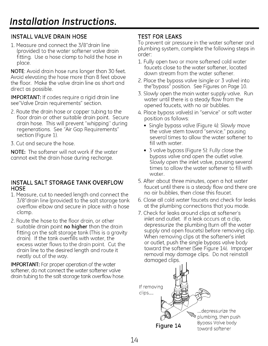
7. Check for leaks around clips at softener's
inlet and outlet. If a leak occurs at a clip,
depressurize the plumbing (turn off the water
supply and open faucets) before removing clip.
When removing clips at the softener's inlet
or outlet, push the single bypass valve body
toward the softener (See Figure 1/4). Improper
removal may damage clips. Do not reinstall
damaged clips.
If removing
clips.....
Figure 14
....depressurize the
plumbing, then push
Bypass Valve body
toward softener
14
Installation Instructions.
ADD WATER AND SALT TO THE SALT
STORAGE TANK
WARNING!
EXCESSIVEWEIGHT HAZARD:
Use two or more people to move end lift
solt bogs. Failure to do so con result in
beck or other injuries.
1. Using a container, add about three gallons of
clean water into the salt storage tank.
2. Add salt to the storage tank. Use nugget,
pellet or coarse solar salts with less than 1%
impurities.
PLUG IN THE WATER SOFTENER
1. Plug the water softener into an electrical outlet
that is not controlled by a switch.
2. Replace the top cover.
3. Replace the salt hole cover.
NOTE: The water heater is filled with hard
water and,as hot water is used, it will refill
with conditioned water. In a few days, the hot
water will be fully conditioned. To have fully
conditioned hot water immediately, wait until
the initial recharge is over. Then, drain the water
heater(following instructions for water heater) until
water runs cold.
-- WARNING! Discard all unused parts
and packaging material after installation.
Small parts remaining after the installation
could be a choke hazard.
SANITIZE THE WATER SOFTENER/SANITIZE
AFTER SERVICE
1. Open salt hole cover, remove the brinewell cover
and pour about 3 oz. (6tablespoons) of household
bleach into the softener brinewell. Replace the
brinewell cover.
2. Hake sure the bypass valve(s)is in the
"service"(open)position.
3. Start a recharge (regeneration). See"Start a
Recharge'on Page 13.
4. After the recharge has completed, fully open a
cold water faucet, downstream from the softener,
and allow 50 gallons of water to passthrough
the system. Thisshould take at least 20 minutes.
Closethe faucet.
15
Programming the Water Softener.
Salt Level
Clock
Hardness
Recharge
1 orlmll-lr] GollonslMin I
I.... % Remainin_t I
I_ _ r'_ Days to Empty /
IHHHCa,,to,Service/
I___ Recharge Now / _
,,,,,oo,0 ,,i!) "
|. Set ..) char
Today/Now/Cancel
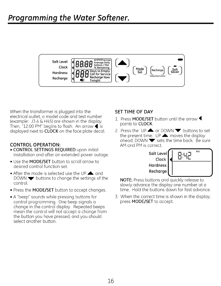
When the transformer is plugged into the
electrical outlet, a model code and test number
(example: J3.a & Has) are shown in the display.
Then, "12:00 PM" begins to flash. An arrow _ is
displayed next to CLOCK on the face plate decal.
CONTROL OPERATION:
•CONTROLSETTINGSREQUIREDupon initial
installation and after an extended power outage.
° Use the MODE/SET button to scroll arrow to
desired control function set.
•After the mode is selected use the UP ,_- and
DOWN _V buttons to change the settings of the
control.
• Press the MODE/SET button to accept changes.
•A "beep" sounds while pressing buttons for
control programming. One beep signals a
change in the control display. Repeated beeps
mean the control will not accept a change from
the button you have pressed, and you should
select another button.
SET TIME OF DAY
1. Press MODEISET button until the arrow
points to CLOCK.
2. Press the UP AIL or DOWN _W" buttons to set
the present time. UP ,A, moves the display
ahead; DOWN _W"sets the time back. Be sure
AN and PiVtis correct.
Salt Levelf J-I.I I-1 PH
Clock I' o.-,c
Hardness /
Recharge L
NOTE: Press buttons and quickly release to
slowly advance the display one number at a
time. Hold the buttons down for fast advance.
3. When the correct time is shown in the display,
press MODE/SET to accept.
16
Programming the Water Softener.
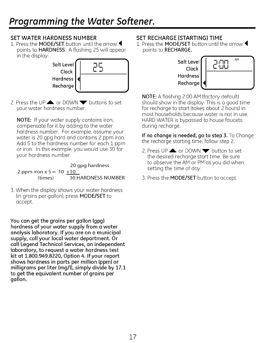
SET WATER HARDNESS NUMBER
1. Press the MODE/SET button until the arrow
points to HARDNESS. A flashing 25 will appear
in the display.
Salt Level r ]
Clock /
Hardness I'
Recharge l -
2. Press the UP_b. or DOWN _r" buttons to set
your water hardness number.
NOTE: If your water supply contains iron,
compensate for it by adding to the water
hardness number. For example, assume your
water is 20 gpg hard and contains 2 ppm iron.
Add 5 to the hardness number for each lppm
or iron. In this example, you would use 30 for
your hardness number.
20 gpg hardness
2ppmironx5= 10 +10
(times) 30 HARDNESS NUMBER
SET RECHARGE (STARTING} TIME
1. Press the MODE/SET button until the arrow
points to RECHARGE.
Salt Levellr __,i-lt-I A.
Clock [4 IZ'UU
Hardness
Recharge
NOTE: A flashing 2:00 AM (factory default)
should show in the display. This is a good time
for recharge to start (takes about 2 hours)in
most households because water is not in use.
HARD WATER is bypassed to house faucets
during recharge.
If no change is needed, go to step 3. To Change
the recharge starting time, follow step 2.
2. Press UP_b, or DOWN V button to set
the desired recharge start time. Be sure
to observe the AM or PMas you did when
setting the time of day.
3. Press the PIODE/SET button to accept.
5. When the display shows your water hardness
(in grains per gallon), press PIODE/SET to
accept.
You can get the grains per gallon (gpg)
hardness of your water supply from a water
analysis laboratory. If you are on a municipal
supply, call your local water department. Or
call Legend Technical Services, an independent
laboratory, to request a water hardness test
kit at 1.800.949.8220, Option 4. If your report
shows hardness in parts per million (ppm) or
milligrams per liter (mg/I), simply divide by 17.1
to get the equivalent number of grains per
gallon.
17
Programming the Water Softener.
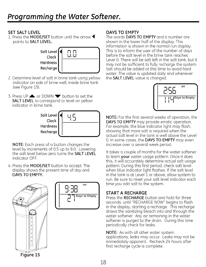
SET SALT LEVEL
1. Press the MODE/SET button until the arrow 4
points to SALT LEVEL.
Solt Level
Clock
Hordness
Rechorge
2. Determine level of salt in brine tank using yellow
indicator on side of brine well, inside brine tank
(see Figure 15).
3. Press UP _b, or DOWN _P" button to set the
SALT LEVELto correspond to level on yellow
indicator in brine tank.
Solt Level
Clock |
Hordness |
Rechorge [.
111_'2
-!.D
NOTE: Each press of a button changes the
level by increments of 0.5 up to 8.0. Lowering
the salt level below zero turns the SALT LEVEL
indicator OFF.
4. Press the MODE/SET button to accept. The
display shows the present time of day and
DAYS TO EMPTY. [iD.70 P. 1
3.]0
"7 "7 Days to Empty
CI
Figure 15
DAYS TO EMPTY
The words DAYSTO EMPTYand a number are
shown in the lower half of the display. This
information is shown in the normal run display.
This isto inform the user of the number of days
before the salt level in the brine tank reaches
Level 0. There will be salt left in the salt tank, but it
may not be sufficient to fully recharge the system.
Salt should be added at this time to avoid hard
water. The value is updated daily and whenever
the SALT LEVELvalue is changed.
7.1-1- A.
,:_.n,n_ _1
1l,_,,oo ,o m0j
NOTE: For the first several weeks of operation, the
DAYSTO EMPTY may provide erratic operation.
For example, the blue indicator light may flash,
showing that more salt is required when the
actual salt level in the tank is well above the Level
0. In some cases, the DAYSTO EMPTYmay even
increase over a several week period.
It takes a couple of months for the water softener
to learn your water usage pattern. Once it does
this, it will accurately determine actual salt usage
pattern. During this first period, check salt level
when blue indicator light flashes. If the salt level
in the tank is at Level 1 or above, allow system to
run. Be sure to reset your salt level indicator each
time you add salt to the system.
START A RECHARGE
Press the RECHARGE button and hold for three
seconds, until "RECHARGE NOW" begins to flash
in the display, starting a recharge. This recharge
draws the sanitizing bleach into and through the
water softenen Any air remaining in the water
softener is purged to the drain. During this time
periodically check for leaks.
NOTE: As with all other water system
applications, leaks may occun Leaks may not be
immediately apparent. Recheck 24 hours after
first recharge cycle is complete.
18
Programming the Water Softener.
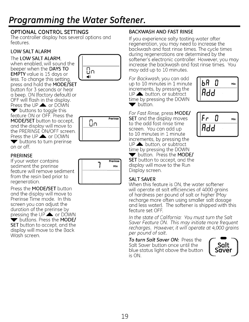
OPTIONAL CONTROL SETTINGS
The controller display has several options and
features.
LOW SALTALARM
The LOW SALT ALARM,
when enabled, will sound the
beeper when the DAYS TO
EMPTYvalue is 15 days or
less. To change this setting,
press and hold the MODE/SET
button for 3 seconds or hear
a beep. ON (factory default) or
OFFwill flash in the display.
Press the UP_b. or DOWN
V' buttons to toggle this
feature ON or OFF.Press the
MODE/SET button to accept,
and the display will move to
the PRERINSEON/OFF screen.
Press the UP _b. or DOWN
_r buttons to turn prerinse
on or off.
Prerinse]
Dn
PRERINSE
If your water contains
sediment the prerinse
feature will remove sediment
from the resin bed prior to
regeneration.
Press the MODE/SET button
and the display will move to
Prerinse Time mode. In this
screen you can adjust the
duration of the prerinse by
pressing the UP,b. or DOWN
_r" buttons. Press the MODEl
SET button to accept, and the
display will move to the Back
Wash screen.
BACKWASH AND FAST RINSE
If you experience salty tasting water after
regeneration, you may need to increase the
backwash and fast rinse times. The cycle times
during regenerations are determined by the
softener's electronic controller. However, you may
increase the backwash and fast rinse times. You
may add up to 10 minutes.
For Backwash, you can add
up to 10 minutes in 1 minute
increments, by pressing the
UP Ab. button, or subtract
time by pressing the DOWN
_T button.
For Fast Rinse, press MODEl
SETand the display moves
to the add fast rinse time
screen. You can add up
to 10 minutes in 1minute
increments, by pressing the
UP _ button, or subtract
time by pressing the DOWN
_T" button. Press the MODE/
SET button to accept, and the
display will move to the Run
Display screen.
Rdd
SALTSAVER
When this feature is ON, the water softener
will operate at salt efficiencies of 4000 grains
of hardness per pound of salt or higher (May
recharge more often using smaller salt dosage
and less water). The softener is shipped with this
feature set OFF.
In the state of California: You must turn the Salt
Saver Feature ON. This may initiate more frequent
recharges. However, it will operate at 4,000 grains
per pound of salt.
To turn Salt Saver ON: Press the
Salt Saver button once until the
blue status light above the button
is ON.
19
Programming the Water Softener.
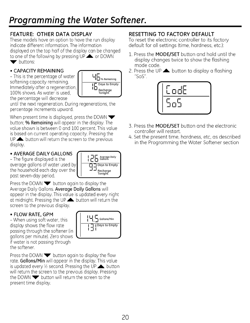
FEATURE: OTHER DATA DISPLAY
Thesemodelshave an option to havethe run display
indicate different information.The information
displayedon the top half of the displaycan be changed
to one of the following by pressingUP ,A, or DOWN
_V buttons:
° CAPACITYREMAINING .,--
- Thisis the percentageof water II I II-
--I 0 °/° Remaining /
softening capacity remaining. II IC Days to Empty J
Immediatelyafter a regeneration,II
lO0%shows. Aswater is used, _1 lU_g_ih_h_?eJ
the percentagewiii decrease
untiI the next regeneration.During regenerations,the
percentageincrements upward.
When present time is displayed,pressthe DOWN_r'
button: % Remainingwill appear in the dispIay.The
valueshown is between0 and 100percent.Thisvalue
isbased on current operating capacity. Pressingthe
UP_b. button will return the screento the previous
display.
• AVERAGE DALLYGALLONS
- Thefigure displayed is the
averagegallons of water used by
the householdeach day over the
past seven-dayperiod.
I _-- Average Daily 1
C0 Go,o..
Cl =l Days to Empty
__I__IRecharge
Tonight
Pressthe DOWN_r' button again to disptaythe
AverageDailyGallons.Average Daily Gallonswill
appear in the dispiay.Thisvalue is updated every night
at midnight. Pressingthe UP_b. button will return the
screento the previousdisplay.
• FLOW RATE, GPM
- Whenusing soft water, this
display shows the flow rate
passingthrough the softener(in
gallons per minute).Zeroshows
if water is not passingthrough
the softener.
I LI.S Go,o.s/._.
--I I Days to Empty
-i!
, ,_
Pressthe DOWN_Y button again to displaythe flow
rate. Gallons/Min wilt appear in the display.Thisvalue
is updated every Vzsecond.Pressingthe UP,A, button
wili return the screento the previousdispiay.Pressing
the DOWN_F" button will returnthe screento the
present time display.
RESETTING TO FACTORY DEFAULT
To reset the electronic controller to its factory
default for all settings (time, hardness, etc.):
1. Press the MODE/SET button and hold until the
display changes twice to show the flashing
mode code.
2. Press the UP _k, button to display a flashing
"SOS".
OOC
,)
3. Press the MODE/SET button and the electronic
controller will restart.
/4.Set the present time, hardness, etc, as described
in the Programming the Water Softener section
20
Programming the Water Softener.
POWER OUTAGE MEMORY
If electrical power to the water softener is lost,
"memory" built into the timer circuitry will keep
all settings for up to 24 hours. While the power
is out, the display is blank and the water softener
will not regenerate. When electrical power is
restored, the following will occur:
Reset the present time only if the display is
flashing. The HARDNESSand RECHARGETIME
never require resetting unless a change is desired.
Even if the clock is incorrect after a long power
outage, the softener operates as it should to keep
your water soft. However, regenerations may
occur at the wrong time of day until you reset the
clock to the correct time of day.
NOTE: If the water softener was regenerating
when power was lost, it will now finish the cycle.
BLUE INDICATOR LIGHT
Steady blue light indicates that the unit isworking
correctly. The light flashes when the unit needs
attention from the user.
• Light will also flash when power to until has
been interrupted. Check the PRESENTTIME
setting.
• Light flashes and DAYSTO EMPTYflashes -
check salt level and add salt as required.
• Light flashes and Err is in the display - electrical
problem with system.
LOW SALT SIGNAL
When the DAYSTO EMPTYdrops to 15, the blue
indicator light and DAYSTO EMPTYin the display
will flash every second and the alarm will beep
every 50 seconds (from 8:00 AM to 8:00 PM),to
notify the user that the unit is running low on
salt. As soon as any button is pressed, the alarm
will stop beeping. The blue indicator light and
DAYSTO EMPTYwill continue to flush. Once salt
is added to the brine tank and the SALT LEVEL is
reset, the DAYSTO EMPTYwill be reset.
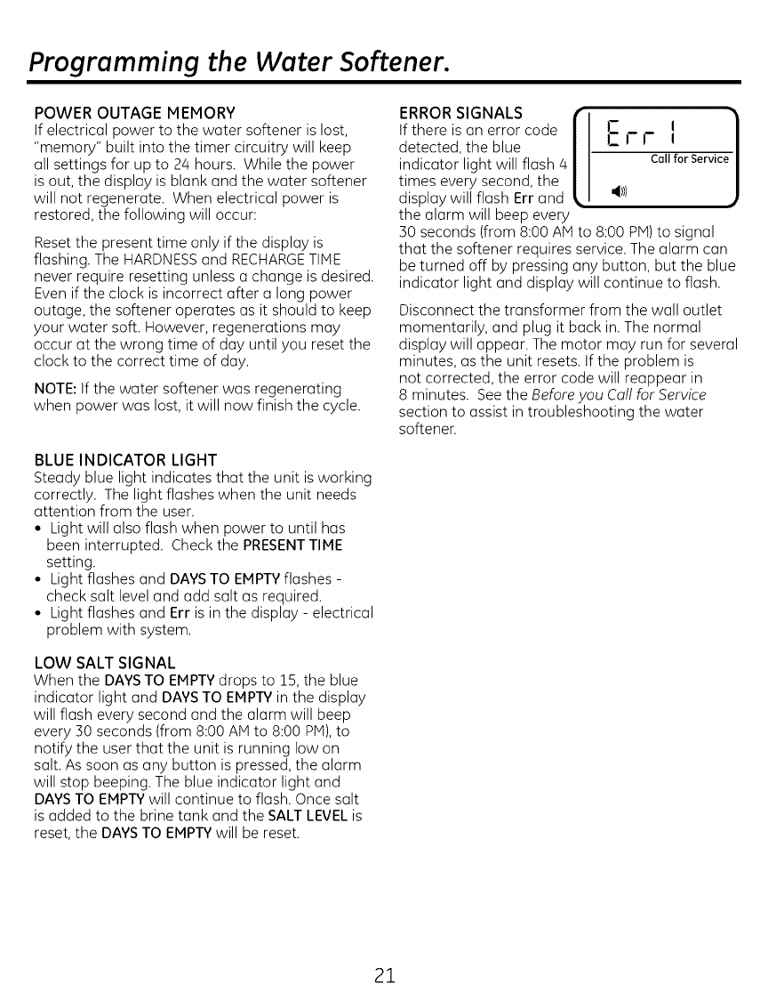
ERROR SIGNALS [ J/
If there is an error code I- I 1
detected, the blue IZ I- !-
indicator light will flash 4 Call forServic
times every second, the
display will flash Err and . 4t))
the alarm will beep every
50 seconds (from 8:00 AM to 8:00 PM)to signal
that the softener requires service. The alarm can
be turned off by pressing any button, but the blue
indicator light and display will continue to flash.
Disconnect the transformer from the wall outlet
momentarily, and plug it back in. The normal
display will appear. The motor may run for several
minutes, as the unit resets. If the problem is
not corrected, the error code will reappear in
8 minutes. See the Before you Coil for Service
section to assist in troubleshooting the water
softener.
21
Care and cleaning.
ADJUSTING YOUR WATER HARDNESS
The blend adjusting knob (Figure 16) gives the
ability to finely adjust hardness of the treated water
leaving the water softener. If slightly harder water
is desired than is normally delivered by the water
softener, the blend adjusting knob can divert a small
stream of hard water and blend it with the soft water
entering the home. The amount of water diverted is
controlled by turning a blend adjusting knob on the
end cap of the valve stem.
NOTE:To get full performance from your water
softener leave blending valve in the factory closed
position.
To make adjustments to water hardness:
1. Hold bypass handle to keep the valve stem
from rotating (see figure 16). Loosen hex nut on
blend adjustment knob by turning the hex nut
counterclockwise.
2. TO INCREASE HARDNESS: With the bypass in
the service position (see figure 16) hold the handle
to keep the valve stem from rotating and turn the
blend adjusting knob counterclockwise up to 2
turns from the closed position. It is recommended
that adjustments be made in quarter turn
increments over several weeks until the desired
hardness is achieved. NOTE: Once an adjustment
is made to the blend valve knob the change in
water hardness at the homes faucets or shower
heads may take several days to be noticed. This
delay is due to the large amounts of already
conditioned water in the pipes and water heater
that must be exchanged before a change in
hardness can be noticed. Have the water tested
to determine the actual water hardness.
3. TO DECREASE HARDNESS: With the bypass in
the service position (see figure 16) hold the handle
to keep the valve stem from rotating and turn the
blend adjusting knob clockwise. When the knob
will not turn anymore, hard water is no longer
being blended into the soft water.
/4. Once the desired hardness is achieved tighten the
hex nut (see figure 16) clockwise until it comes in
contact with the bypass stem.
NOTE: To meet the water softener performance
specifications and reduction of barium and radium
claims the adjustable hardness must be kept in
the "OFF" position. The off position is achieved
when the blend adjusting knob is fully rotated
clockwise until it stops.
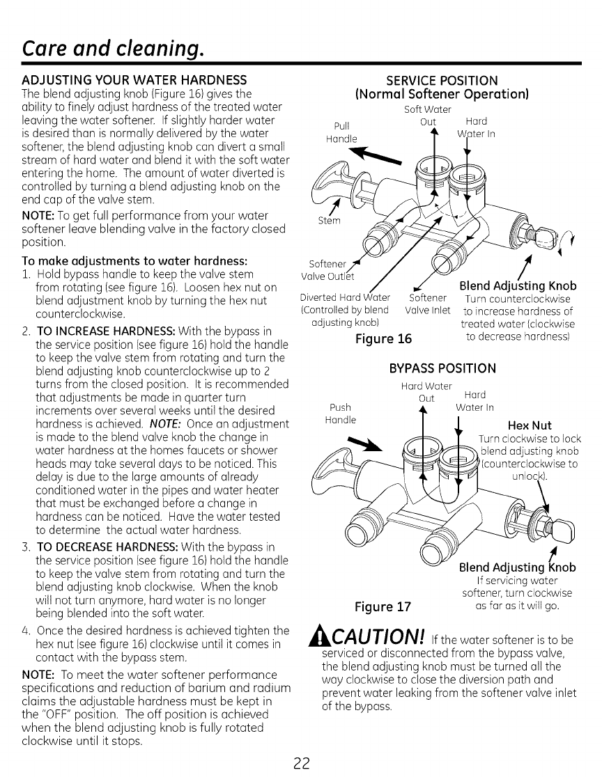
SERVICE POSITION
(Normal Softener Operation)
Soft Water
Pult Out Hard
Handle ]ter In
Stem
Softener./_
Valve Outlet /
Diverted Hard Water
(Controlled by blend
adjusting knob)
Figure 16
Softener
Valve Inlet
Blend Adjus/_ting Knob
Turn counterdockw)se
to increase hardness of
treated water (clockwise
to decrease hardness)
Push
Handle
BYPASS POSITION
Hard Water
Out Hard
Water In
Hex Nut
Turn clockwise to lock
blend adjusting knob
(counterclockwise to
unlock).
Figure 17
Blend Adjusting K_nob
If serv)c)ng water
softener, turn dockw)se
as for as it will go.
,i I,CAUTION! If the water softener isto be
serviced or disconnected from the bypass valve,
the blend adjusting knob must be turned all the
way clockwise to close the diversion path and
prevent water leaking from the softener valve inlet
of the bypass.
22
Care and cleaning.
CHECKING THE SALT STORAGE LEVEL end
REFILL
Brine (salt dissolved in water)is needed for each
and every recharge. The water for making brine
is metered into the gait storage area by the water
softening system valve and control. However, you
must keep the tank supplied with salt.
ADDING SALT
Lift the salt hole cover and check the salt storage
level frequently. If the water softener uses all
the salt before you refill it, you will experience
hard water. Until you have established a refilling
routine, check the salt every two or three weeks.
Always add if less than 1/4 full. Be sure the
brinewell cover is on.
NOTE: if using potassium chloride (KCI),do not fill
above level 4 on the brinewell decal.
NOTE: In humid areas, it is best to keep the salt
storage level lower, and to refill more often to
avoid salt "bridging".
Recommended Salt: Nugget, pellet or coarse
solar salts with less than 1% impurities.
Salt Not Recommended: Rock salt, high in
impurities, block, grandulated table, ice melting,
ice cream making salts, etc.
_CAUTION:
Water softening salt with iron removing
additives:
Some suits mey hove on odditive to help the
woter softening system hendle iron in the
water supply. Although this additive may
help to keep the woter softening system
resin cleon, it may olso release corrosive
fumes thet weoken end shorten the life of
some water softening system parts.
CLEANING IRON OUT OF THE WATER
SOFTENI NG SYSTEM
Your water softening system takes hardness
minerals (calcium and magnesium) out of
the water. Also, it can control some (see the
Specification Guidelines section) "clear water" iron.
With clear water iron, water from a faucet
is clear when first put into a glass. After 15 to 30
minutes, the water begins to cloud or turn rust
colored. A water softening system will not remove
any iron that makes the water cloudy
or rusty as it comes from the faucet (called red
water iron). To take red water iron out of water,
or over the maximum of clear water iron,
an iron filter or other equipment is needed.
If your water supply has clear water iron, periodic
resin bed cleaning is needed. GE recommends
using Super Iron Out_'brand resin bed cleaner
to thoroughly clean your resin bed if your iron
content is high. Clean the bed at least every six
months, or more often if iron appears in the soft
water between cleanings.
IMPORTANT:It is important to mix the resin bed
cleaner with water (following the manufacturer's
instructions), pour it into the brinewell (see Figure
9)and recharge the softener immediately. Do not
pour the resin bed cleaner
in with the salt, as it will not be as effective in
cleaning the resin, and can cause damage to
the softener if it is left in the brine tank for an
extended period due to the corrosive gases
that are formed.
23
Routine Maintenance.
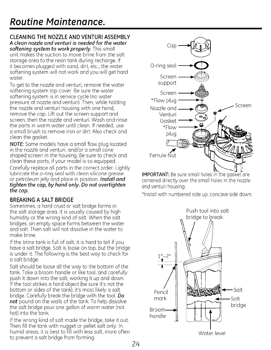
CLEANING THE NOZZLE AND VENTURI ASSEMBLY
Aclean nozzle and venturi is needed for the water
softening system to work properly. This small
unit makes the suction to move brine from the salt
storage area to the resin tank during recharge. If
it becomes plugged with sand, dirt, etc., the water
softening system wilt not work and you will get hard
water.
To get to the nozzleand venturi, remove the water
softening system top cover. Be sure the water
softening system is in service cycle (no water
pressure at nozzleand venturi). Then, while holding
the nozzleand venturi housing with one hand,
remove the cap. Lift out the screen support and
screen, then the nozzle and venturi. Wash and rinse
the parts in warm water until clean. If needed, use
a small brush to remove iron or dirt. Also check and
clean the gasket.
NOTE:Some models have a small flow plug located
in the nozzle and venturi, and/or a small cone
shaped screen in the housing. Be sure to check and
clean these parts, if your model is so equipped.
Carefully replace all parts in the correct order. Lightly
lubricate the o-ring seal with clean silicone grease
or petroleum jelly and place in position. Install and
tighten the cap, by hand only. Do not overtighten
the cap.
BREAKINGA SALTBRIDGE
Sometimes, a hard crust or salt bridge forms in
the salt storage area. It isusually caused by high
humidity or the wrong kind of salt. When the salt
bridges, an empty space forms between the water
and salt. Then salt will not dissolve in the water to
make brine.
If the brine tank is full of salt, it is hard to tell if you
have a salt bridge. Salt is loose on top, but the bridge
is under it.The following is the best way to check for
a salt bridge.
Salt should be loose all the way to the bottom of the
tank. Takea broom handle or like tool, and carefully
push it down into the salt, working it up and down.
If the tool strikes a hard object (besure it's not the
bottom or sides of the tank), it's most likely a salt
bridge. Carefully break the bridge with the tool. Do
not pound on the walls of the tank. To help dissolve
the salt bridge pour one gallon of warm water (not
hot)into the tank.
If the wrong kind of salt made the bridge, take it out.
Then fill the tank with nugget or pellet salt only. In
humid areas, it is best to fill with less salt, more often
to prevent a salt bridge from forming.
Screen _i
*Flow plug "--_
Nozzle and _._ _I _ Screen
Venturi
plug
Ferrule N_tut
IMPORTANT:Besure small holesin the gasket are
centereddirectly over the small holesin the nozzle
and venturi housing.
*Installwith numberedside up, concave side down.
24
7
Pencil
mark
Broom--
handle
Push tool into salt
bridge to break
i
_ _Salt
--Salt
bridge
Water level
Before you call for service.
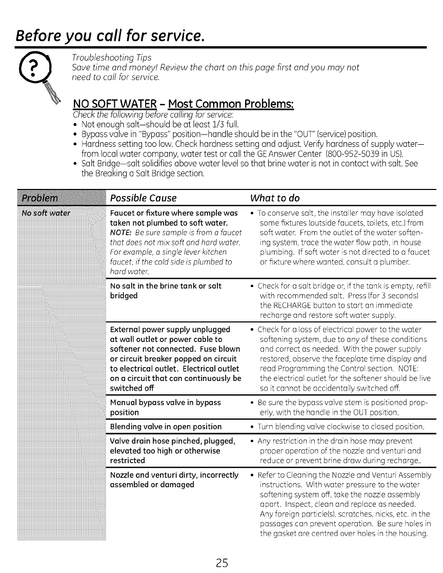
Troubleshooting Tips
Save time and money! Review the chart on this page first and you may not
need to call for service.
NO SOFT WATER - Most Common Problems:
Check the following before calling for service:
• Not enough salt-should be at least 1/3 full.
• Bypass valve in "Bypass" position-handle should be in the "OUT" (service) position.
• Hardness setting too low. Check hardness setting and adjust. Verify hardness of supply water-
from local water company, water test or call the GEAnswer Center (800-952-5039 in US).
• Salt Bridge-salt solidifies above water level so that brine water is not in contact with salt. See
the Breaking a Salt Bridge section.
Possible Cause What to do
Foucet or fixture where somple wos
token not plumbed to soft woter.
NOTE: Be sure sample is from a faucet
that does not mix soft and hard water.
For example, a single lever kitchen
faucet, if the cold side is plumbed to
hard water.
• To conserve salt, the installer may have isolated
some fixtures (outside faucets, toilets, etc.) from
soft water. From the outlet of the water soften-
ing system, trace the water flow path, in house
plumbing. If soft water is not directed to a faucet
or fixture where wanted, consult a plumber.
• Check for a salt bridge or, if the tank is empty, refill
with recommended salt. Press (for 3 secondsl
the RECHARGEbutton to start an immediate
recharge and restore soft water supply.
• Check for a loss of electrical power to the water
softening system, due to any of these conditions
and correct as needed. With the power supply
restored, observe the faceplate time display and
read Programming the Control section. NOTE:
the electrical outlet for the softener should be live
so it cannot be accidentally switched off.
• Be sure the bypass valve stem is positioned prop-
erly, with the handle in the OUT position.
• Turn blending valve clockwise to closed position.
• Any restriction in the drain hose may prevent
proper operation of the nozzle and venturi and
reduce or prevent brine draw during recharge..
• Refer to Cleaning the Nozzle and Venturi Assembly
instructions. With water pressure to the water
softening system off, take the nozzle assembly
apart. Inspect, clean and replace as needed.
Any foreign particle(s), scratches, nicks, etc. in the
passages con prevent operation. Be sure holes in
the gasket are centred over holes in the housing.
25
Before you call for service.
Possible Cause What to do
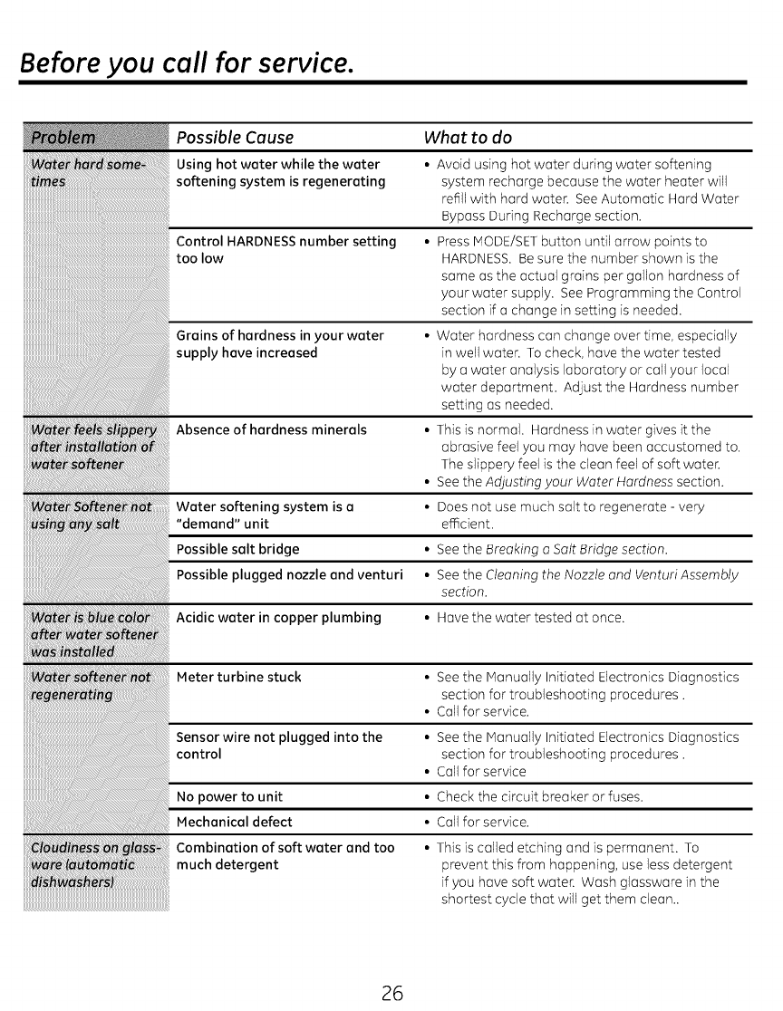
Using hot water while the water • Avoid using hot water during water softening
softening system is regenerating system recharge because the water heater will
refill with hard water. See Automatic Hard Water
Bypass During Recharge section.
Control HARDNESS number setting • Press MODE/SETbutton until arrow points to
too low HARDNESS. Be sure the number shown is the
same astheactualgrainspergallonhardnessof
yourwatersupply.See Programming theControl
sectionifo change insettingisneeded.
Grains of hardness in your water • Water hardness can change over time, especially
supply have increased in well water. To check, hove the water tested
by o water analysis laboratory or call your local
water deportment. Adjust the Hardness number
setting as needed.
Absence of hardness minerals • This is normal. Hardness in water gives it the
abrasive feel you may hove been accustomed to.
The slippery feel is the clean feel of soft water.
• See the Adjusting your Water Hardness section.
Water softening system is a• Does not use much salt to regenerate - very
"demand" unit el_cient.
Possible salt bridge • See the Breaking a Salt Bridge section.
Possible plugged nozzle and venturi • See the Cleaning the Nozzle and Venturi Assembly
section.
Acidic water in copper plumbing • Hove the water tested at once.
Meter turbine stuck • See the Manually Initiated Electronics Diagnostics
section for troubleshooting procedures.
• Call for service.
Sensor wire not plugged into the • See the Manually Initiated Electronics Diagnostics
control section for troubleshooting procedures.
• Coil for service
No power to unit • Check the circuit breaker or fuses.
Mechanical defect • Coil for service.
Combination of soft water and too • This is called etching and is permanent. To
much detergent prevent this from happening, use less detergent
if you hove soft water. Wash glassware in the
shortest cycle that will get them cleon..
26
Before you call for service.
Possible Cause What to do
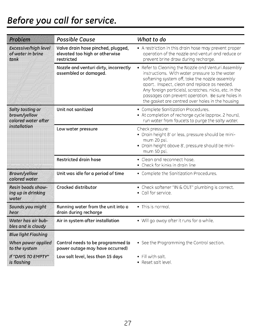
Valve drain hose pinched, plugged,
elevated too high or otherwise
restricted
Nozzle and venturi dirty, incorrectly
assembled or damaged.
Unit not sanitized
Lowwaterpressure
iiiiiiiiiiiiiiiiiiiiiiiiiiiiiiiiiiiiiiiiiiiiiiiiiiiiiiiiiiiiiiiiiiiiiiiiiiiiiiiiiiiiiiiiiiiiiiiiiiiiiiiiiiiiiiii
Restricted drain hose
Unit was idle for a period of time • Complete the Sanitization Procedures.
Cracked distributor • Check softener "IN & OUT" plumbing is correct.
• Coilfor service.
Running water from the unit into a • This is normal.
drain during recharge
Air in system after installation • Will go away after it runs for o while.
• A restriction in this drain hose may prevent proper
operation of the nozzle and ventufi and reduce or
prevent brine draw during recharge.
• Refer to Cleaning the Nozzle and Venturi Assembly
instructions. With water pressure to the water
softening system off, take the nozzle assembly
aport. Inspect, cleon and replace as needed.
Any foreign particle(s), scratches, nicks, etc. in the
passages con prevent operation. Be sure holes in
the gasket ore centred over holes in the housing
• Complete Sonitizotion Procedures.
• At completion of recharge cycle (approx. 2 hours),
run water from faucets to purge the salty water.
Check pressure:
• Drain height 8' or less, pressure should be mini-
mum 20 psi.
• Drain height above 8',pressure should be mini-
mum 50 psi.
• Cleon and reconnect hose.
• Check for kinks in drain line
iiiiii_i_i!_i_ii!ii!ii!__!_Ji%_!_i!_i_!iiiiiiiiiiiiiiiiiiiiiiiiiiiiiiiiiiiiiiiiiiiiiiiiiiiiiiii_i_i_ilil_l_i
Control needs to be programmed {a
power outage may have occurred)
Low salt level, less than 15 days
• Seethe Programming the Control section.
• Fill with salt.
• Reset salt level.
27
Before you call for service.
Possible Cause
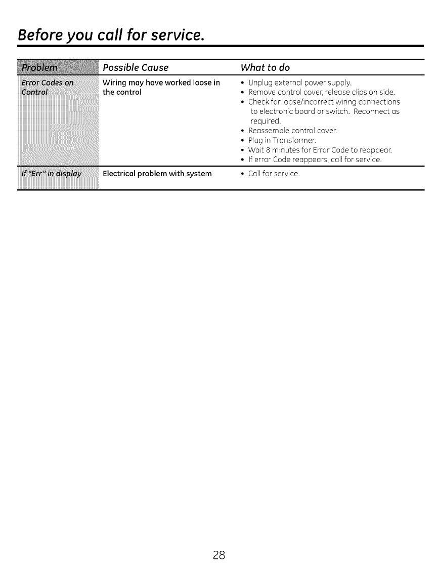
Wiring may hove worked loose in
the control
What to do
• Unplug external power supply.
• Remove control cover, release clips on side.
• Check for loose/incorrect wiring connections
to electronic board or switch. Reconnect as
required.
• Reassemble control cover.
• Plug in Transformer.
• Wait 8 minutes for Error Code to reappear.
• If error Code reappears, call for service.
i_'Ei_di_ay Electrical problem with system • Call for service.
iiiiiiiiiiiiiiiiiiiiiiiiiiiiiiiiiiiiiiiiiiiiiiiiiiiiiiiiiiiiiiiiiiiiiiiiiiiiiiiiiiiiiiiiiiiiiiiiiiiiiiiiiiiiiiii
28
Advanced troubleshooting for service.
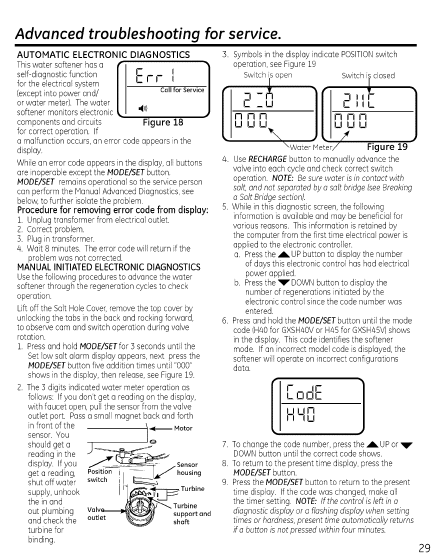
AUTOMATIC ELECTRONIC DIAGNOSTICS
Thiswater softener hasa f
self-diagnosticfunction [
for the electricalsystem
(exceptinto powerand/
or water meter). The water
softener monitors electronic .
componentsand circuits
for correct operation. If
Err l ]
Call for service/
J
Figure 18
a malfunctionoccurs, an error codeappears in the
display.
Whilean error codeappears in the display,all buttons
are inoperable exceptthe MODE/SETbutton.
MODE/SETremainsoperational so the service person
can perform the ManualAdvancedDiagnostics,see
below,to further isolatethe problem.
Procedure for removing error code from display:
1. Unplugtransformer from electrical outlet.
2. Correctproblem.
3. Hug in transformer.
4. Wait 8 minutes. The error codewill return if the
problemwas not corrected.
MANUAL INITIATED ELECTRONICDIAGNOSTICS
Usethe following proceduresto advancethe water
softenerthrough the regenerationcyclesto check
operation.
Lift off the SaltHoleCover,remove the top cover by
unlockingthe tabs in the back and rockingforward,
to observecam and switch operation during valve
rotation.
1. Pressand holdMODE/SETfor3 seconds until the
Setlowsalt alarm display appears,next pressthe
MODE/SETbutton five addition times until "000"
shows in the display,then retease,see Figure 19.
2. The 3 digits indicated water meter operation as
follows: If you don't get a reading onthe display,
with faucet open,pull the sensorfrom the valve
outtet port. Passa small magnet back and forth
in front of the
sensor. You
should get a
reading in the
display. If you
get a reading,
shut off water
supply,unhook
the in and
out plumbing
and checkthe
turbine for
binding.
outlet
Turbine
support end
short
3. Symbolsin the display indicate POSITIONswitch
operation,see Figure19
Switch is open
2 ,_, Switch i_closed
,_--'llr
rl rl rl rl rl rl
UUU
, U U U'r',%-- , f ,_
\Water Meter/ Figure 19
4 UseRECHARGEbutton to manuallyadvancethe
valve into each cycleand check correct switch
operation. NOTE:Besure water isin contact with
salt,and notseparated by asalt bridge (seeBreaking
a SaltBridgesection).
5. Whilein this diagnosticscreen,the following
information isavailable and may be beneficial for
various reasons. Thisinformation is retained by
the computer from the first time electrical power is
appliedto the electronic controller.
a. Pressthe _b.UP button to displaythe number
of days this electronic control hashad electrical
power applied.
b. Pressthe _VDOWN button to displaythe
number of regenerationsinitiated by the
electroniccontrol since the code numberwas
entered.
6. Pressand holdthe NODE/SETbuttonuntil the mode
code (H40for GXSH40Vor H45 for GXSH45V)shows
in the display. This codeidentifies the softener
mode. If an incorrect model code is displayed,the
softener will operate on incorrect configurations
data.
It, ]
LooE
lln
H- u
To change the code number,press the Ab.UP or _V'
DOWNbutton until the correct code shows.
To return to the present time display,pressthe
NODE/SETbutton.
Pressthe NODE/SETbutton to returnto the present
time display. If the codewas changed, make all
the timer setting. NOTE:If the controlisleft in a
diagnosticdisplayor a flashingdisplay when setting
timesor hardness,presenttime automatically returns
if a button is not pressedwithin four minutes.
Advanced troubleshooting for service.
Service: Manually Advance Recharge Check
NOTE: The control display must show a steady time (not
flashing).
1. Press the RECHARGEbutton and hold in for three
seconds. RECHARGEbegins to flash as the water
softening system enters the fill cycle of recharge.
Remove the brinewell cover and, using a flashlight,
observe fill water entering the brine tank. If water
does not enter the tank, look for an obstructed nozzle,
venturi, fill flow plug or brine tubing. See Care and
Cleaning of the Water Softener System section.
2. After observing fill, press the RECHARGEbutton to
move the water softening system into brining. A
slow flow of water to the drain will begin. Verify brine
draw from the brine tank by shining a flashlight into
the brinewell and observing a noticeable drop in the
liquid level over an extended period of time (is to 20
minutes).
NOTE: Be sure a salt bridge is not preventing water from
contacting salt. See Care and cleaning of the water
softening system section.
If the water softening system does not draw brine, check:
, nozzle and/or venturi dirty or defective.
, defective nozzle and venturi seal.
, nozzle and venturi not seated properly
on gasket.
, other inner valve defect (rotor seal, rotor and disc,
wave washer, etc.).
, restricted drain (check drain fitting and hose).
NOTE: If water system pressure is low, an elevated drain
hose may cause back pressure, stopping brine draw.
5. Again, press the RECHARGEbutton to move the water
softening system into backwash. Look for a fast flow
of water from the drain hose. A slow flow indicates a
plugged top distributor, backwash flow plug or drain
hose.
4. Press the RECHARGEbutton to move the water
softening system into fast rinse. Again look for a fast
drain flow. Allow the water softening system to rinse
for afew minutes to flush out any brine that may
remain in the resin tank from the brining cycle test.
5. To return the water softening system to service, press
the RECHARGEbutton.
30
Exploded View.
ii
4
55
29
36m
m19
(_o
24m
23
{
}
25
31
Exploded View.
139
124
109--
I
1i0---------0
113
118
Cross-section
View
132
134 133
147
148
152
--152
32
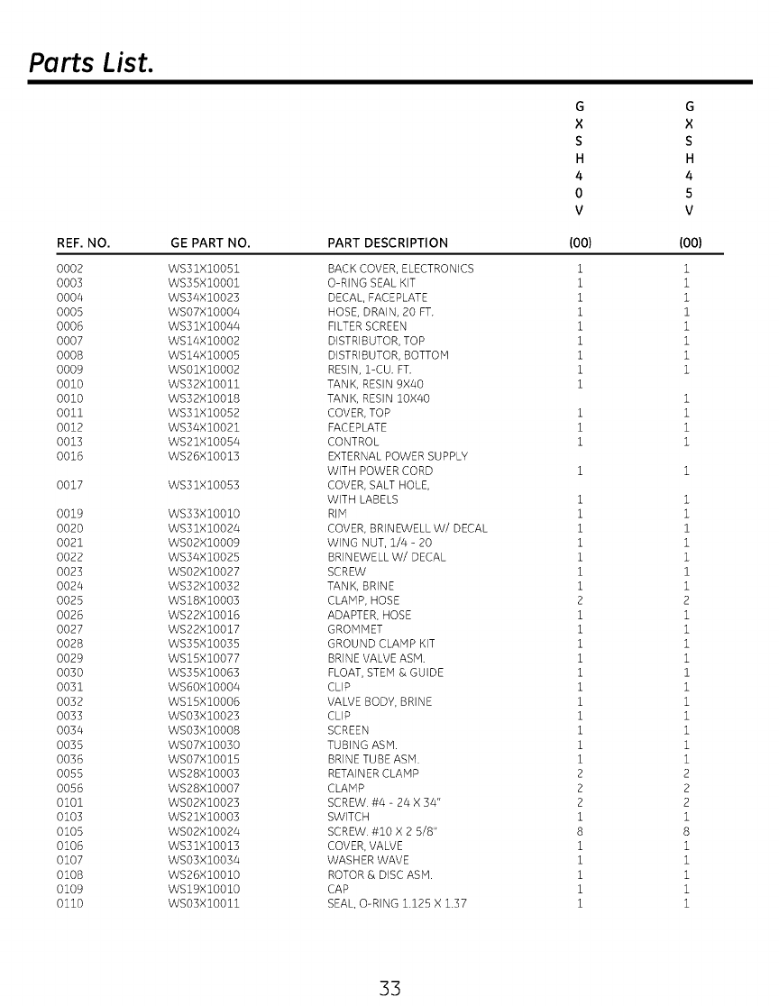
Parts List.
REF. NO.
O0O2
0003
0004
0005
0006
0007
0008
0009
0010
0010
0011
0012
0013
0016
0017
0019
0020
0021
0022
0023
0024
0025
0026
0027
0028
0029
0030
0031
0032
0033
0034
0035
0036
0055
0056
0101
0103
0105
0106
0107
0108
0109
0110
G
X
S
GE PART NO.
WS31XlO051
WS35XlO001
WS34XlO023
WSO7XIO004
WS31XlO044
WSI4XlO002
WS14XIO005
WSO1XIO002
WS32XlO011
WS32XlO018
WS31XlO052
WS34XlO021
WS21XlO054
WS26XlO013
WS31XlO053
WS33XlO010
WS31XlO024
WSO2XlO009
WS34XlO025
WSO2XlO027
WS32XlO032
WS18XlO003
WS22XlO016
WS22XlO017
WS35XlO035
WS15XlO077
WS35XZO063
WS6OXIO004
WS15XIO006
WSO3XlO023
WSO3XIO008
WSO7XIOO30
WSO7XIO015
WS28XlO003
WS28XZO007
WSO2XZO023
WS2ZXZO003
WSO2XZO024
WS31XlO013
WSO3XlO034
WS26XlO010
WSI9XIO010
WSO3XIO011
PART DESCRIPTION
BACK COVER, ELECTRONICS
O-RING SEAL KIT
DECAL, FACEPLATE
HOSE, DRAIN, 20 FT.
FILTER SCREEN
DISTRIBUTOR, TOP
DISTRIBUTOR, BOTTOM
RESIN, 1-CU. FT.
TANK, RESIN 9X40
TANK, RESIN lOX40
COVER, TOP
FACEPLATE
CONTROL
EXTERNAL POWER SUPPLY
WITH POWER CORD
COVER, SALT HOLE,
WITH LABELS
RIM
COVER, BRINEWELL W/DECAL
WING NUT, 1/4 - 20
BRINEWELL W/DECAL
SCREW
TANK, BRINE
CLAMP, HOSE
ADAPTER, HOSE
GROMMET
GROUND CLAMP KIT
BRINE VALVE ASM.
FLOAT, STEM & GUIDE
CLIP
VALVE BODY, BRINE
CLIP
SCREEN
TUBING ASM.
BRINE TUBE ASM.
RETAINER CLAMP
CLAMP
SCREW. #4 - 24 X 34"
SWITCH
SCREW. #10 X 2 5/8"
COVER, VALVE
WASHER WAVE
ROTOR ,9, DISC ASM.
CAP
SEAL, O-RING 1.125 X 1.37
H
4
0
V
(oo)
i
i
i
i
i
i
i
i
i
i
i
i
33
1
1
1
1
1
1
1
2
1
1
1
1
1
1
1
1
1
1
1
2
2
2
1
8
1
1
1
1
1
G
X
S
H
4
5
V
(00)
i
i
i
1
i
i
i
i
i
i
i
i
1
1
i
1
1
i
1
2
1
1
1
1
i
1
1
1
1
1
1
2
2
2
1
8
1
1
1
1
1
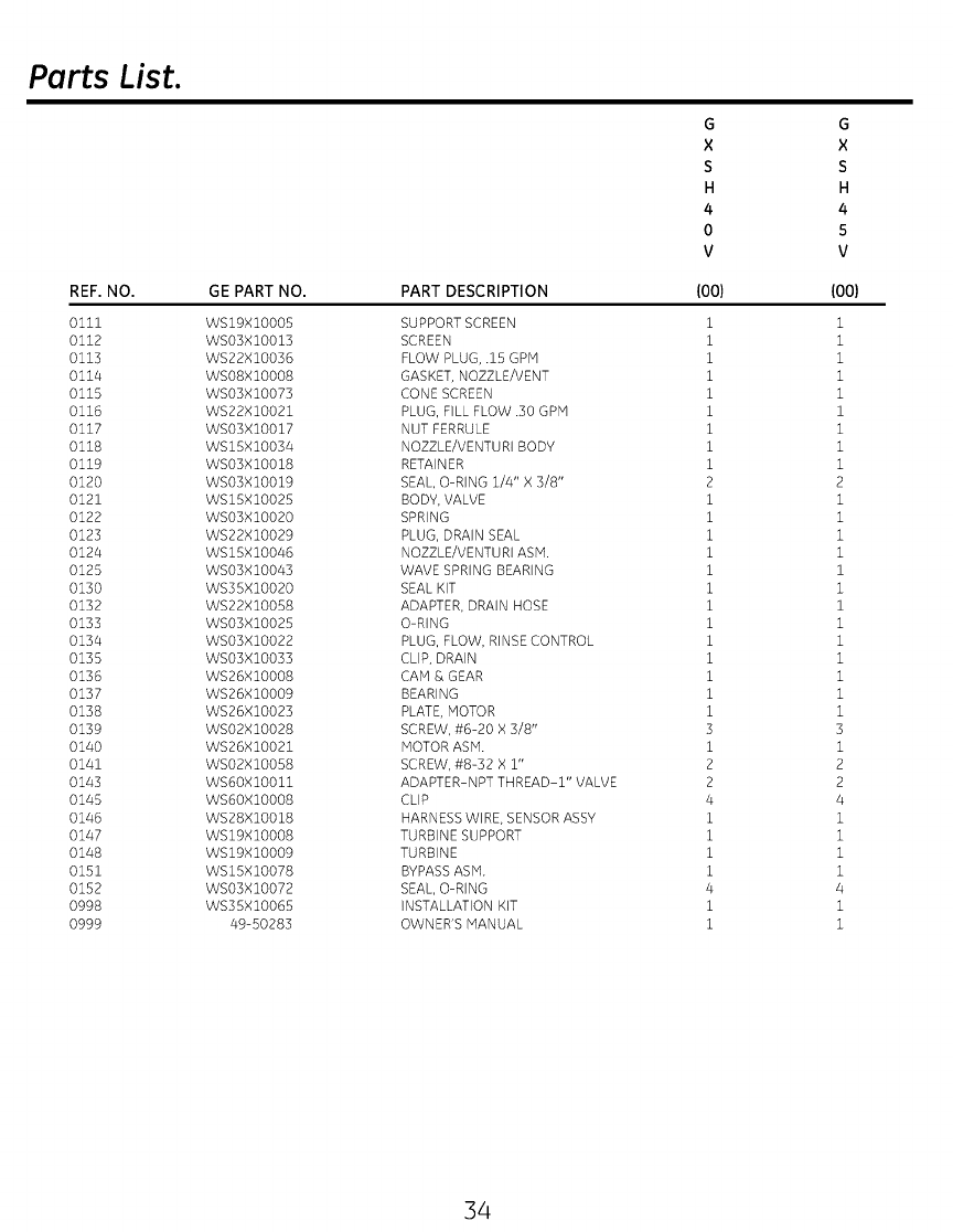
Parts List.
REF. NO.
Olii
o112
o113
o114
o115
o116
o117
o118
o119
o12o
o121
0122
0123
0124
0125
0130
0132
0133
0134
0135
0136
0137
0138
0139
0140
0141
0143
0145
0146
0147
0148
0151
0152
0998
0999
G
X
S
H
4
0
V
GE PART NO.
WS19XIOO05
WSO3XIOOl3
WS22XlOO36
WSO8XIOO08
WSO3XlOB73
WS22X10021
WSO3XIOOl7
WS15XlO034
WSO3XIO018
WSO3XlOB19
WS15X10025
WSO3XIO020
WS22X10029
WS15XlOO46
WSO3XlO043
WS35XlOO20
WS22XlOO58
WSO3XlOO25
WSO3XIOO22
WSO3XIOO33
WS26XlOOO8
WS26XlOO09
WS26XlOO23
WSO2XlOO28
WS26XlOO21
WSO2XlOO58
WS6OXIOOll
WS60XlOB08
WS28X10018
WS19XlOB08
WS19XlOB09
WS15X10078
WSO3XlOB72
WS35X10065
49-50283
PART DESCRIPTION
SUPPORT SCREEN
SCREEN
FLOW PLUG, .15 GPM
GASKET, NOZZLE/VENT
CONE SCREEN
PLUG, FILL FLOW .30 GPM
NUT FERRULE
NOZZLE/VENTURI BODY
RETAINER
SEAL, O-RING 1/4" X 3/8"
BODY, VALVE
SPRING
PLUG, DRAIN SEAL
NOZZLE/VENTURI ASM.
WAVE SPRING BEARING
SEAL KIT
ADAPTER, DRAIN HOSE
O-RING
PLUG, FLOW, RINSE CONTROL
CLIP, DRAIN
CAM & GEAR
BEARING
PLATE, MOTOR
SCREW, #6-20 X 3/8"
MOTOR ASM.
SCREW, #8-32 X i"
ADAPTER-NPT THREAD-l" VALVE
CLIP
HARNESS WIRE, SENSOR ASSY
TURBINE SUPPORT
TURBINE
BYPASS ASM.
SEAL, O-RING
INSTALLATION KIT
OWNER'S MANUAL
(oo)
1
1
1
1
1
1
1
1
1
2
1
1
1
1
1
1
1
1
1
1
1
1
1
3
1
2
2
4
1
1
1
1
4
1
1
G
X
S
H
4
5
V
(00)
1
1
1
1
1
1
1
1
1
2
1
1
1
1
1
1
1
1
1
1
1
1
1
3
1
2
2
4
1
1
1
1
4
1
1
34
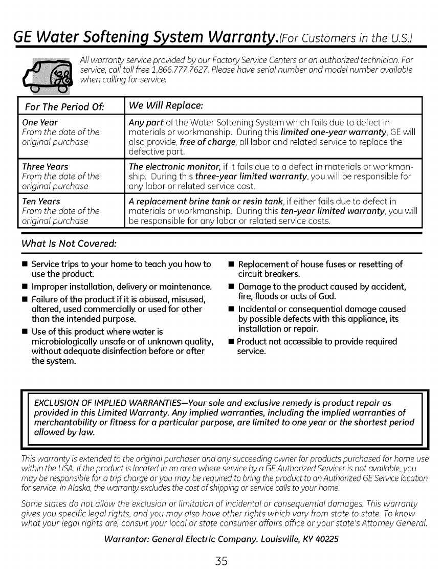
GE Water Softening System Warranty.lEar Customersintheu.s.l
All warranty serviceprovided by our Factory Service Centersor an authorized technician. For
service,call toll free 1.866.777.7627.Pleasehave serial number and model number available
when calling for service.
For The Period Of'. We Will Replace:
One Year Any part of the Water Softening System which fails due to defect in
From the date of the materials or workmanship. During this limited one-year warranty, GEwill
original purchase also provide, free of charge, all labor and related service to replace the
defective part.
Three Veers The electronic monitor, if it fails due to a defect in materials or workman-
From the date of the ship. During this three-year limited warranty, you will be responsible for
original purchase any labor or related service cost.
TenYears A replacement brine tank or resin tank, if either foils due to defect in
From the date of the materials or workmanship. During this ten-year limited warranty, you will
original purchase be responsible for any labor or related service costs.
What Is Not Covered:
•Service trips to your home to teach you how to
use the product.
• Improper installation, delivery or maintenance.
• Failure of the product if it is abused, misused,
altered, used commercially or used for other
then the intended purpose.
• Use of this product where water is
microbiologicelly unsafe or of unknown quality,
without adequate disinfection before or after
the system.
• Replacement of house fuses or resetting of
circuit breakers.
• Damage to the product caused by accident,
fire, floods or acts of God.
• Incidental or consequential damage caused
by possible defects with this appliance, its
installation or repair.
• Product not accessible to provide required
service.
EXCLUSION OF IMPLIED WARRANTIES--Your sole and exclusive remedy is product repair as
provided in this Limited Warranty. Any implied warranties, including the implied warranties of
merchantability or fitness for aparticular purpose, are limited to one year or the shortest period
allowed by law.
This warranty is extended to the original purchaser and any succeeding owner for products purchased for home use
within the USA. If the product is located in on area where service by oGEAuthorized Servicer is not available, you
may be responsible for o trip charge or you may be required to bring the product to on Authorized GEService location
for service. In Alaska, the warranty excludes the cost of shipping or service coils to your home.
Some states do not allow the exclusion or limitation of incidental or consequential damages. Thiswarranty
gives you specific legal rights, and you may also hove other rights which vary from state to state. Toknow
whot your legal rights ore, consult your local or state consumer affairs office oryour state's Attomey General.
Warrantor: General Electric Company. Louisville, KV 40225
35
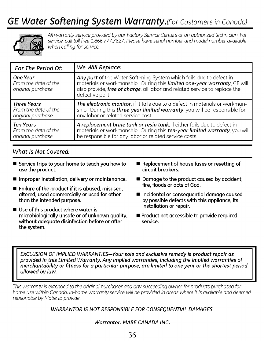
GE Water Softening System Warranty.(ForCustomers in Canada)
All warranty serviceprovided by our Factory Service Centersor an authorized technician. For
service,call toll free 1.866.777.7627.Pleasehave serial number and model number available
when calling for service.
For The Period Of'. We Will Replace:
One Year Any part of the Water Softening System which fails due to defect in
From the date of the materials or workmanship. During this limited one-year warranty, GEwill
original purchase also provide, free of charge, all labor and related service to replace the
defective part.
Three Years The electronic monitor, if it fails due to a defect in materials or workman-
From the date of the ship. During this three-year limited warranty, you will be responsible for
original purchase any labor or related service cost.
TenYears A replacement brine tank or resin tank, if either fails due to defect in
From the date of the materials or workmanship. During this ten-year limited warranty, you will
original purchase be responsible for any labor or related service costs.
What Is Not Covered:
•Service trips to your home to teach you how to
use the product.
• Improper installation, delivery or maintenance.
•Failureof the product if it isabused, misused,
altered, used commercially or used for other
than the intended purpose.
• Use of this product where water is
microbiologically unsafe or of unknown quality,
without adequate disinfection before or after
the system.
• Replacement of house fuses or resetting of
circuit breakers.
• Damage to the product caused by accident,
fire, floods or acts of God.
• Incidental or consequential damage caused
by possible defects with this appliance, its
installation or repeir.
• Product not accessible to provide required
service.
EXCLUSION OF IMPLIED WARRANTIES--Your sole and exclusive remedy is product repair as
provided in this Limited Warranty. Any implied warranties, including the implied warranties of
merchantability or fitness for aparticular purpose, are limited to one year or the shortest period
allowed by law.
Thiswarranty is extended to the original purchaser and any succeeding owner for products purchased for
home use within Canada. In-home warranty service will be provided in areas where it is available and deemed
reasonable by Mabe to provide.
WARRANTOR IS NOT RESPONSIBLE FOR CONSEQUENTIAL DAMAGE&
Warranton MABE CANADA INC.
36
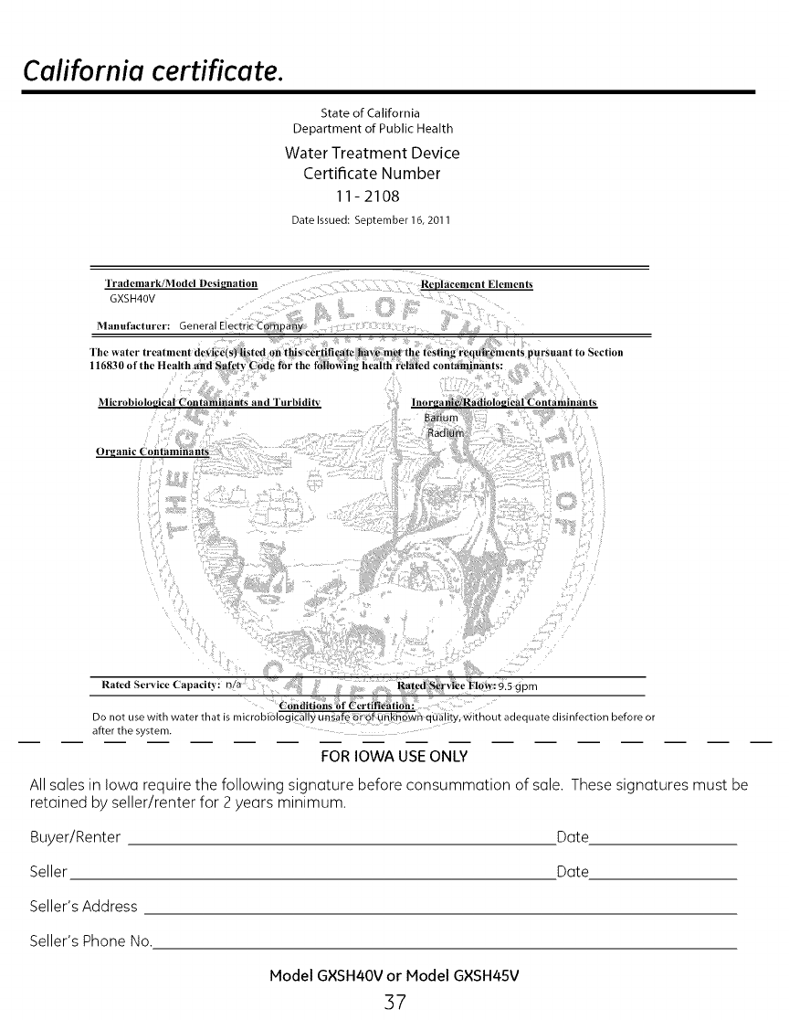
California certificate.
State of California
Department of Public Health
Water Treatment Device
Certificate Number
11-2108
Date Issued: September 16, 2011
lrademark/Model Designation
GXSH40V
Manufacturer: General Electrk-Company
The _+aler |rearlnen
116830 of the Health and Safety
Microbiological Contaminants and "lurbidit_
Repldcement Elements
cction
Organic Contaminants
Rated Serv ce Capac ty n/a Rated S_r,;icc Flow:9.5 gpm
Conditions bf ('ertifie_tlon:
Do not use with water that is microbiologically unsafe or of unknown ouality, without adequate disinfection before or
after the system.
FOR IOWA USE ONLY
All soles in Iowa require the following signature before consummation of sole. These signatures must be
retained by seller/renter for 2 years minimum.
Buyer/Renter Dote
Seller Dote
Seller's Address
Seller's Phone No.
Model GXSH40V or Model GXSH45V
37
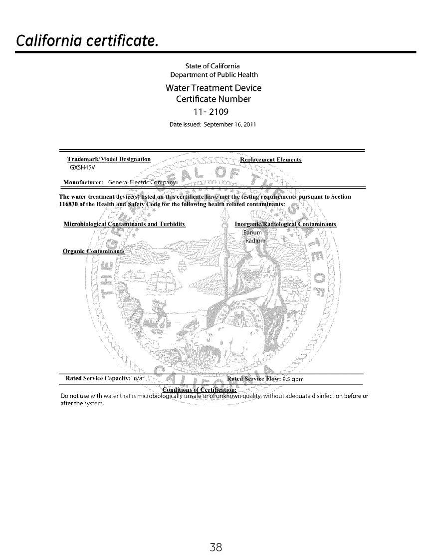
California certificate.
State of California
Department of Public Health
Water Treatment Device
Certificate Number
11 - 2109
Date Issued: September 16, 2011
Trademark/Model Designation
GXSH45V
Manufacturer: 3eneral ElectricCompa_y
The water treatment de+ice{
Replacenlent Elenlents
Microbiolo
Organic ('on_amiilantS
and Turbidity
Rated Service Capacity: n/a Rated_S_rvige Flow: 9.5 gpm
Conditions Of _erfifleation:
Do not use with water _na_ is microbiologically unsafe or ofunkflown oua ty, without adequate disinfection before or
after the s stem.
38

Notes.
39

Notes.
40
Informaci6n sabre Seguridad ......... 42
Especificaciones y Dimensiones ...... 43
Acerca del Suavizante ................ 46
Antes de Comenzar ................... 47
Requisitos de Instalaci6n .......... 48-50
Instrucciones de Instalaci6n ....... 51-55
Programaci6n del Suavizante ...... 56-61
Cuidado y Limpieza ................ 62, 63
Rutina de Mantenimiento ............. 64
Antes de solicitar el servicio .............
t_cnico ............................ 65-68
Vista Ampliadal Listado de Piezas. 71-74
Garantia (EE.UU.)..................... 75
Garantia (Canad6) .................... 76
41
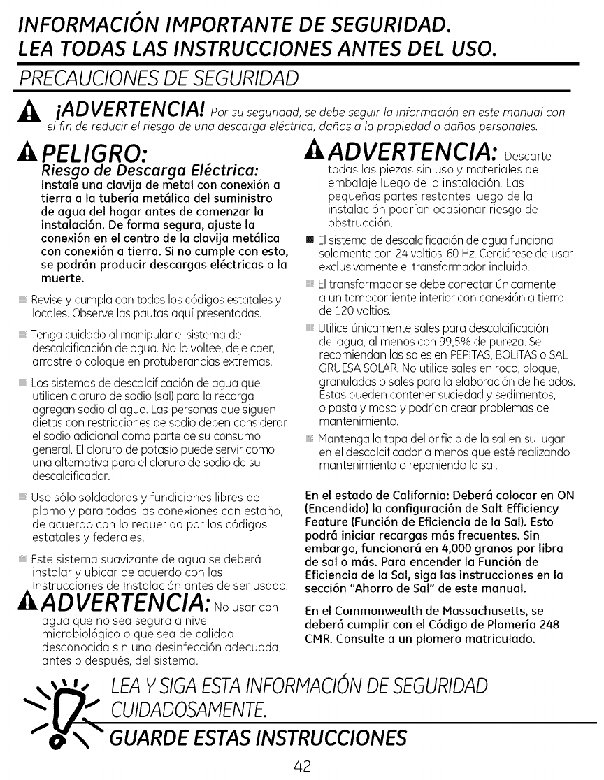
INFORMACION IMPORTANTE DE SEGURIDAD.
LEA TODAS LAS INSTRUCCIONES ANTES DEL USO.
PRECAUCIONESDE SEGURIDAD
,_, iADVERTENCIA! po_su seguridad, se debe seguir /a informaci6n en este manual con
el fin de reducir el riesgo de una descarga eldctrica, dahos a la propiedad o dahos personales.
kPELIGRO:
Riesgo de Descarga El_ctrica:
Instale una clavija de metal con conexi6n a
tierra a la tuberia met61ica del suministro
de agua del hogar antes de comenzar la
instalaci6n. De forma segura, ajuste la
conexi6n en el centro de la clavija met61ica
con conexi6n a tierra. Si no cumple con esto,
se podr6n producir descargas el_ctricas o la
muerte.
Revisey cumpla con todos los c6digos estatales y
locales.Observe las pautas aquf presentadas.
Tenga cuidado al manipular el sistema de
descalcificaci6n de agua. No Io voltee, deje caer,
arrastre o coloque en protuberancias extremas.
Lossistemas de descalcificaci6n de agua que
utilicen cloruro de sodio (sal)para la recarga
agregan sodio al agua. Laspersonas que siguen
dietas con restricciones de sodio deben considerar
el sodio adicional como parte de su consumo
general. Elcloruro de potasio puede servir como
una alternativa para el cloruro de sodio de su
descalcificador.
Use s61osoldadoras y fundiciones libres de
plomo y para todas las conexiones con estar%,
de acuerdo con Io requerido por los c6digos
estatales y federales.
Este sistema suavizante de agua se debera
instalar y ubicar de acuerdo con las
nstrucciones de Instalaci6n antes de ser usado.
ADVERTENCIA: No.sarcon
agua que no sea segura a nivel
microbiol6gico o que sea de calidad
desconocida sin una desinfecci6n adecuada,
antes o despu@s,del sistema.
,IkADVERTENCIA: Descarte
todas las piezas sin uso y materiales de
embalaje luego de la instalaci6n. Las
pequeflas partes restantes luego de la
instalaci6n podr[an ocasionar riesgo de
obstrucci6n.
[] Elsistema de descalcificaci6n de agua funciona
solamente con 24 voltios-60 Hz.Cerci6rese de usar
exclusivamente el transformador incluido.
Eltransformador se debe conectar Linicamente
a un tomacorriente interior con conexi6n a tierra
de 120 voltios.
Utilice 0nicamente sales para descalcificaci6n
del agua, al menos con 99,5% de pureza. Se
recomiendan las sales en PEPlTAS,BOUTASo SAL
GRUESASOLAR.No utilice sales en roca,bloque,
granuladas o sales para la elaboraci6n de helados.
Estaspueden contener suciedad y sedimentos,
o pasta y masa ypodrfan crear problemas de
mantenimiento.
Mantenga la tapa del orificio de la sal en su lugar
en el descalcificador a menos que est@realizando
mantenimiento o reponiendo la sal.
En el estado de California: Deber6 colocar en ON
(Encendido) la configuraci6n de Salt Efficiency
Feature (Funci6n de Eficiencia de la SaIL Esto
podr6 iniciar recargas m6s frecuentes. Sin
embargo, funcionar6 en 4,000 granos por libra
de sal o m6s. Para encender la Funci6n de
Eficiencia de la Sal, siga las instrucciones en la
secci6n "Ahorro de Sal" de este manual.
En el Commonwealth de Massachusetts, se
deber6 cumplir con el C6digo de Plomeria 248
CMR. Consulte a un plomero matriculado.
%11 SVSIGA STAINFOnMACIONS GUnI A
CUIDADOSAMENTE.
/_; GUARDE ESTAS INSTRUCCIONES
42
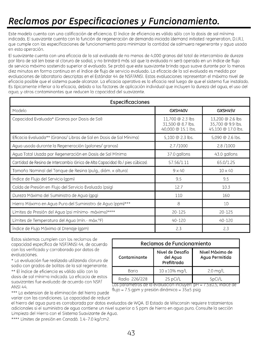
Reclamos por Especificaciones y Funcionamiento.
Este modelo cuenta con una calificaci6n de eficienda. El indice de eficienda es vc_lido s61o con la dosis de sal minima
indicada. El suavizante cuenta con la funci6n de regenerad6n de demanda iniciada (demand initiated regeneration, D.kR,),
que cumple con las especificaciones de funcionamiento para minimizar la cantidad de salmuera regenerante y agua usada
en esta operad6n.
El suavizante cuenta con una eficacia de la sal evaluada de no menos de 4,000 granos del total de intercambio de dureza
por libra de sal (en base at cloruro de sodio), y no brindar@ m@s sal que la evaluada ni sere] operado en un fndice de flujo
de servicio mc]ximo sostenido superior al evaluado. Se prob6 que este suavizante brinda agua suave durante por Io menos
diez minutos en forma continua en el fndice de flujo de servicio evaluado. La eficacia de la sal evaluada es medida por
evaluaciones de laboratorio descriptas en el Est@ndar 84 de NSF/ANSI, Estas evaluaciones representan el m@ximo nivel de
eficacia posible que el sistema puede atcanzar, La eficacia operativa es la eficacia real luego de que el sistema fue instalado.
Es tfpicamente inferior a la eficacia, debido a los factores de aplicaci6n individual que incluyen la dureza del agua, el uso del
agua, y otros contaminantes que reducen la capaddad del suavizante.
Especificaciones
Modelo
Capacidad Evaluada* (Granos por Dosis de Sat)
Eficada Evatuada** (@ranos/Libras de Sat en Dosis de Sat Minima)
Agua usada durante la Regeneraci6n (gatones/granos)
Agua Total Usada por Regeneraci6n en Dosis de Sal Minima
CantidaddeResinade Intercambio16nicode AltaCapacidad(Ib/pies c0bicos)
Tama_o Nominal del Tanque de Resina(puig.,di6m. x altura)
indice de Flujodel Servicio (gpm)
Caida de Presi6n en Flu]odel Servido Evatuado (psi@
Dureza M6xima del Suministro de Agua (gpg)
Hierro M6ximo en Agua Pura del Suministro de Agua (ppm)***
@mitesde Presi6n del Agua (psi minimo m6ximo)....
@mitesde Temperatura del Agua (min. m6x.°F)
indice de FlujoM6ximo al Drenaje (gpm)
GXSH40V
ii,700 @ 2,5 Ibs
31,500 @ 8.7 Ibs,
40,000 @ 15,1 Ibs.
5,100 @ 2.3 Ibs,
2.7/1000
37,0 gallons
57,56/1,11
9 x40
9.5
12,7
110
8
20 125
40 120
2.3
GXSH45V
13200 @2,6 Ibs
55,700 @ 9,9 Ibs,
45,100 @ 17,0 Ibs.
5,090 @ 2.6 Ibs,
2.8/1000
430 gallons
65.0/1,25
10 x 40
9.5
10,3
160
10
20 125
40 120
2.3
Estossistemas cumplen con los reclamos de
capacidad especifica de NSF/ANSI4£ de acuerdo
con los verificado y corroborado por datos de
evaluaciones.
* La evaiuaci6n fue realizada utilizando cloruro de
sodio con grados de bolitas de la sal regenerante.
** Elindice de eficiencia esvc_lidos6lo con la
dosis de sal minima indicada, La eficacia de estos
suavizantes fue evaluada de acuerdo con NSF/
Reclamos de Funcionamiento
Nivel de Desafio Nivel M6ximo de
Contaminante deI Agua Agua Permitida
Prefiltrada
Bario 10 _+10% mg/L 2.0 mg/L
Radio 226/228 25 pCi/L 5pCi/L
ANSI 44, _os parametros ae _a evamaaon mcmyen pH : /.b_+U.b,m@ce de
*** La extension de la eliminaci6n del hierro puede flujo : 7.5 gpm y presi6n dine]mica: 35_+5psig
variar con las condiciones. La capacidad de reducir
el hierro del agua pura es corroborada par datos evatuados de WOA. ElEstado de Wisconsin requiere tratamientos
adicionales si el suministro de agua contiene un nivel superior a 5 ppm de hierro en agua pura. Consulte la secci6n
Limpieza del Hierro con el Sistema Suavizante de Agua.
.... @mitesde presi6n en Canad6, 1.4 7,0 kg/cm2,
43
Sobre el sistema de descalcificaci6n de aqua.
SERVICIO
Cuando el sistema descalcificador de agua esta
proporcionando agua descalcificada, a esto se le
llama "Servicio".Durante el servicio, el agua dura
fluye des@ la tuberia de agua principal de la
casa hacia el sistema de descalcificaci6n de agua.
En el interior del tanque de resina del sistema de
descalcificaci6n de agua hay una pelicula o capa
compuesta de miles de resinas plasticas ctiminutas.
Cuando el agua dura pasa a trav6s de la capa, cada
resina diminuta atrapa los minerales duros.A esto se
le llama intercambio de iones.Escomo un iman que
atrae yatrapa metales. Luego, el agua sin minerales
duros (agua descalcificada o agua blanda) fluye
hacia la casa des@ el sistema de descalcificaci6n.
Despu@sde un periodo de tiempo, la capa de
resina se obstruye o se satura con los minerales
duros ydebe limpiarse. Esta limpieza se denomina
recarga. La recarga comienza alas 2:00 AM (ajustado
en fabrica) por el control del sistema
de descalcificaci6n de agua, y consiste en cinco
etapas o ciclos. Estas son FILL(llenadol, BRINING
(proceso de salado), BRINE RINSE (enjuague salado),
BACKWASH (lavado regresivo) y FAST RINSE (lavado
r4pido).
CIRCUNVALACION AUTOM/_TICA DEL AGUA
DURA DURANTE LA RECARGA
Durante la recarga, el suavizante de agua se
coloca autom6ticamente en el modo de tubo de
desviaci6n, permitiendo que el agua dura est@
disponible en el hogar. Una vez que el suavizante
es recargado, el agua es dirigida nuevamente a
trav@sdel suavizante para sea acondicionada.
Sin embargo, se debe evitar el uso de agua
CALIENTE debido a que el calentador de agua se
Ilenar4 con el agua dura.
LLENADO
Lasal disuelta en agua es Ilamada salmuera. La
salmuera es necesaria para limpiar los minerales
duros de las diminutas particulas de resina.Para
formar la salmuera, el agua fluye hacia el interior
del tanque de sal durante el periodo de Ilenado.
SALADO
Durante el proceso de salado, la salmuera se
desplaza del area del tanque de almacenamiento
de la sal hacia el tanque de la resina. La salmuera
es el agente de limpieza necesario para remover los
minerales duros de la capa de resina. Losminerales
duros yla salmuera son descargados hacia el
desag0e.
Laboquilla yelVenturi crean una succi6n para
mover la salmuera, manteniendo un ritmo muy
bajo para obtener la resina de limpieza con la menor
cantidad de sal.
ENJUAGUE DE SALMUERA
Despu@sde que se use una cantidad de salmuera
medida con anterioridad, la v61vulade salmuera
se cierra. Elagua contin0a fluyendo en la misma
trayectoria que durante el proceso de salado,
excepto por elflujo de salmuera discontinuado.
Losminerales duros yla salmuera fluyen
del tanque de resina hacia el desag0e.
LAVADO REGRESIVO
Durante el lavado regresivo,el agua viaja hacia
arriba a trav@sdel tanque de resina a un flujo de
ritmo r6pido, purgando el hierro acumulado, la
suciedad, ylos sedimentos desde la capa de
resina hacia el desag0e.
ENJUAGUE R/_PIDO
Ellavado regresivo es seguido por un flujo de agua
r6pido hacia abajo a trav@sdel tanque de resina.El
flujo r6pido purga la salmuera del fondo del tanque, y
rellena el tanque de resina.
A continuaci6n del enjuague r6pido, el sistema de
descalcificaci6n de agua regresa al servicio de agua
descalcificada.
44
Sobre el sistema de descalcificaci6n de a,qua.
FUNCIONAMIENTO NORMAL, PANTALLAS DE
CONTROL
Durante el funcionamiento normal, la hora actual
del dia y AM o PH y DAYSTO EMPTY(DiAS HASTA
VACIARSE)aparecen en el area de la pantalla de
control.
El sistema se recargara de forma automatica en el
tiempo de recarga presente, seg0n sea necesario.
FUNCION: CONTROLES OPCIONALES DE
RECARGADO
A veces, es posible que usted desee o necesite
una recarga iniciada manualmente. Dos ejemplos:
Usted ha usado mas agua que de costumbre
(hu@spedesen la casa, lavado adicional, etc.) y
quizas se quede sin agua descalcificada antes
de la pr6xima recarga.
Sele acab6 la sal al sistema.
Use una de las funciones siguientes para
comenzar una recarga inmediatamente, o en el
pr6ximo inicio de recarga preprogramada.
RECARGARESTANOCHE
Presione (sin mantener presionado) el bot6n
RECHARGE(RecargarJ. RECHARGETONIGHT
(Recargar Esta NocheJ titila en el area de la
pantalla de control Se realizara una recarga en el
pr6ximo tiempo de inicio de recarga presente Si
decide cancelar esta recarga, presione el mismo
bot6n una vez mas
RECARGARAHORA
Mantenga presionado el bot6n RECHARGE
(Recargad hasta que RECHARGENOW (Recargar
Ahora) comience a titilar en el area de la pantalla
de control El sistema suavizante de agua inicia
una recarga de inmediato y, al finalizar en unas
dos horas, contara con un nuevo suministro
de agua suave Una vez iniciada, ya no podra
cancelar esta recarga
FUNCION: MEMORIA
Si el suministro el@ctrico del sistema de
descalcificaci6n de agua es interrumpido,
la pantalla de control estara en blanco, y la
luz indicadora azul se apaga, pero el control
mantiene la hora correcta por seis horas
aproximadamente. Cuando el suministro es
restaurado, usted tendra que reajustar la hora
actual solamente si la visualizaci6n y la luz
indicadora azul estan intermitentes. Todos los
otros ajustes se mantienen y nunca requieren
ser ajustados a no ser que usted desee hacer
algOn cambio.
Si la hora estci intermitente despu@sde una
interrupci6n prolongada en el suministro el@ctrico,
el sistema de descalcificaci6n de agua continOa
operando como deberfa para proporcionarle agua
descalcificada. Sin embargo, la recarga podrfan
ocurrir a la hora equivocada del dfa
hasta que usted reajuste el control a la hora
correcta del dfa.
CARACTER/STICA/SERVICIO: DIAGNOSTICO
ELECTRONICO AUTOM/_TICO
La computadora de control tiene una funci6n
de diagn6stico automatico para el sistema
el@ctrico(excepto para la energfa de entrada y la
medici6n del agua). La computadora monitorea
los componentes electr6nicos y los circuitos para
una operaci6n correcta. Si ocurre un error, un
c6digo de error aparece en la pantalla de control.
45
Sobre el sistema de descalcificaci6n de aqua.
INFORMACION SABRE LA CONDICION DEL
AGUA
HIERRO
El hierro del agua puede causar manchas en la
ropa y accesorios de plomerfa. Puede alterar de
forma negativa el sabor de la comida, el agua
potable y otras bebidas. El hierro del agua es
medido en partes par mill6n (ppm). El ppm de
hierro total*, y el tipo o tipos* es determinado a
trav6s de analisis qufmicos. Los cuatro tipos de
hierro diferentes en el agua son:
1Hierro ferroso (agua potable)
1Hierro f@rico (agua roja)
1Hierro asociado par bacterias y organismos
1Hierro asociado en forma coloide e inorg6nica
(ferroso o f@rico)
El hierro ferroso (agua potable) es soluble y
se disuelve en agua. Este suavizante de agua
reducir6 cantidades moderadas de este tipo de
hierro (lea las especificaciones). **El hierro ferroso
(agua potable) normalmente se detecta tomando
un ejemplo del agua en una botella o vaso limpios.
Inmediatamente luego de tomarlos, el ejemplo
es clara. A medida que el ejemplo de agua se
asienta, gradualmente se enturbia y se vuelve
levemente amarillo o marr6n a medida que el aire
oxida el hierro. Este normalmente ocurre entre los
15 y 30 minutos.
AI usar el suavizante para reducir el hierro
ferroso (agua potable), agregue 5 granos a
la configuraci6n dura par cada 1 ppm de
hierro ferroso (agua potable). Lea la secci6n
"Configuraci6n del N0mero de Agua Dura).
Los hierros f@ricos (agua roja), y asociados con
bacterias y organismos son insolubles. Este
suavizante de agua no eliminar6 el hierro f@rico
ni las bacterias. Este hierro es visible de forma
inmediata al salir par un grifo, ya que se oxid6
antes de Ilegar al hogar. Aparece en forma de
pequer_as partfculas turbias suspendidas de color
amarillo, anaranjado o rojizo. Una vez que el agua
se asent6 par un perfodo de tiempo, las partfculas
quedan en el fondo del envase. Generalmente,
estos hierros son eliminados del agua a trav6s del
proceso de filtraci6n. Tambi6n se recomienda la
cloraci6n con el hierro con bacterias.
El hierro asociado en forma coloide o inorgcinico
es de forma f6rrica o ferrosa que no se filtrard ni
intercambiarci fuera del agua. Este suavizante de
agua no eliminard el hierro coloidal. En algunas
instancias, el tratamiento puede mejorar el agua
con hierro coloidal. Normalmente, el agua con
hierro coloidal cuenta con un aspecto amarillento
al ser extrddo. Luego de asentarse durante varias
horas, el color persiste yel hierro no se asienta,
sino que permanece suspendido en el agua.
Colloidal and inorganically bound iron is of ferric
or ferrous form that will not filter or exchange
out of water. This water softener will not remove
colloidal iron. In some instances, treatment
may improve colloidal iron water. Colloidal iron
water usually has a yellow appearance when
drown. After standing for several hours, the color
persists and the iron does not settle,but remains
suspended in the water.
SEDIMENTO
El sedimento son partfculas de material fino y
extrar_o suspendidas en el agua. Este suavizante
de agua no eliminard el sedimento. Con gran
frecuencia este material es arcilla o cieno. Las
cantidades extremas de sedimento pueden dar al
agua un aspecto turbio. Un filtro de sedimentos
instalado arriba del suavizante de agua
normalmente corrige esta situaci6n.
* El agua puede contener uno o mcis de los cuatro
tipos de hierro y cualquier combinaci6n de estos.
El hierro total es la suma de los contenidos.
** La capacidad de reducir el hierro del agua
potable es corroborada por datos evaluados de
Wq)A.
CLORO
Lasresinassuavizantesse puedendegradar
en presenciade cloro sobre2 ppm.Siel cloro
excedeestacantidad,es posibleque la resina
experimenteun periodode duraci6n mdscorta.En
estascondiciones,esrecomendableconsiderarla
comprade un sistemadefiltraci6n para hogarGE
Point-Of-Entrycon unfiltro para la reducci6nde
cloro.
46
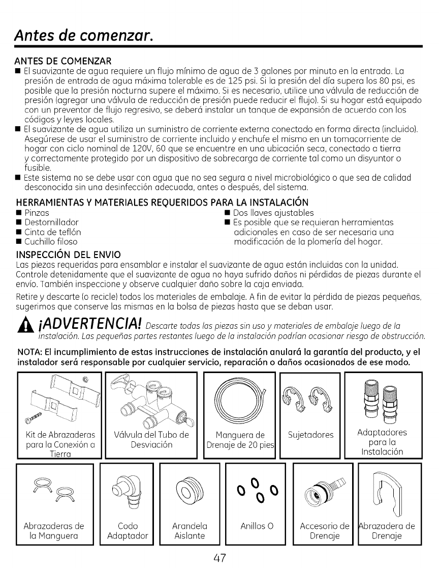
Antes de comenzar.
ANTES DE COMENZAR
• El suavizante de agua requiere un flujo mfnimo de agua de ] galones por minuto en la entrada. La
presi6n de entrada de agua m6xima tolerable es de 125 psi. Si la presi6n del d[a supera los 80 psi, es
posible que la presi6n nocturna supere el m6ximo. Si es necesario, utilice una v61vula de reducci6n de
presi6n (agregar una v61vula de reducci6n de presi6n puede reducir el flujo). Si su hogar est6 equipado
con un preventor de flujo regresivo, se deber6 instalar un tanque de expansi6n de acuerdo con los
c6digos y leyes locales.
• El suavizante de agua utiliza un suministro de corriente externa conectado en forma directa (incluido).
Aseg0rese de usar el suministro de corriente incluido y enchufe el mismo en un tomacorriente de
hogar con ciclo nominal de 120V, 60 que se encuentre en una ubicaci6n seca, conectado a tierra
y correctamente protegido por un dispositivo de sobrecarga de corriente tal como un disyuntor o
fusible.
• Este sistema no se debe usar con agua que no sea segura a nivel microbiol6gico o que sea de calidad
desconocida sin una desinfecci6n adecuada, antes o despu@s, del sistema.
HERRAMIENTAS Y MATERIALES REQUERIDOS PARA LA INSTALACI6N
• Pinzas • Dos Ilaves ajustables
• Destornillador • Es posible que se requieran herramientas
• Cinta de tefl6n adicionales en caso de ser necesaria una
• Cuchillo filoso modificaci6n de la plomerfa del hogar.
INSPECCION DEL ENVIO
Las piezas requeridas para ensamblar e instalar el suavizante de agua est6n incluidas con la unidad.
Controle detenidamente que el suavizante de agua no haya sufrido daflos ni p@didas de piezas durante el
envio. Tambi@n inspeccione y observe cualquier daho sobre la caja enviada.
Retire y descarte (o recicle) todos los materiales de embalaje. A fin de evitar la p@dida de piezas pequehas,
sugerimos que conserve las mismas en la bolsa de piezas hasta que se deban usar.
J_4LiADVERTENCIA! n_con_ to_o_ /o_ sin uso ymateria/es de emba/aje /uego de/a
instalaci6n. Las pequehas partes restantes luego de la instalaci6n podrfan ocasionar riesgo de obstrucci6n.
NOTA: El incumplimiento de estas instrucciones de instalaci6n anular6 la garantia del producto, y el
instalador ser6 responsable por cualquier servicio, reparaci6n o da_os ocasionados de ese modo.
Kit deAbrazaderas
para la Conexi6n a
Tierra
V61vuladel Tubo de
Desviaci6n
O
IVlanguera de
Drenaje de 20 pies
Sujetadores Adaptadores
para la
Instalaci6n
Abrazaderas de
la Manguera
Codo
Adaptador
Arandela
Aislante
°%°
Anillos 0 Accesorio de
Drenaje
_brazadera de
Drenaje
47
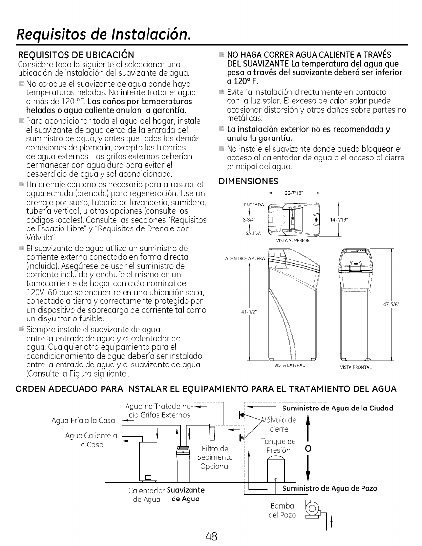
Requisitos de Instoloci6n.
REQUISITOS DE UBICACION
Considere todo lo siguiente al seteccionar una
ubicaci6n de instalaci6n del suavizante de ague.
, No coloque et suavizante de agua donde haya
temperatures hetadas. No intente tratar et ague
amas de 120 °F. Los dafios por temperatures
heladas o ague caliente anulan la garantia.
Pare acondicionartoda elagua delhogar,instale
elsuavizantede agua cerca de laentrada del
suministrode agua, y antes que todas lasdem6s
conexiones de plomeria,excepto lastuber[as
de agua externas.Las grifosexternosdeberian
permanecer con agua dura pare evitarel
desperdiciode agua y salacondicionada.
Un drenajecercano es necesariopara arrastrarel
agua echada (drenada)para regeneraci6n.Use un
drenajepor suelo,tuberiade lavender[a,sumidero,
tuber[avertical,u otrasopciones(consultelos
c6digoslocales).Consultelassecciones"Requisitos
de EspacioLibre"y "Requisitosde Drenajecon
V6tvula".
El suavizante de agua utiliza un suministro de
corriente externa conectado en forma directa
(incluido). Aseg0rese de usar et suministro de
corriente incluido y enchufe el mismo en un
tomacorriente de hogar con ciclo nominal de
120V, 60 que se encuentre en una ubicaci6n seca,
conectado a tierra y correctamente protegido por
un dispositivo de sobrecarga de corriente tal como
un disyuntor o fusible.
Siempre instale et suavizante de agua
entre la entrada de agua y el calentador de
agua. Cualquier otro equipamiento para et
acondicionamiento de agua deberia ser instalado
entre la entrada de agua y et suavizante de agua
(Consulte la Figura siguiente).
NO HAGA CORRERAGUA CALIENTEA TRAVI%
DELSUAVIZANTELatemperature del ague que
pasa a tray,s del suavizante deber6 ser inferior
a120° F.
, Evite la instalaci6n directamente en contacto
con la luz solar. Elexceso de calor solar puede
ocasionar distorsi6n y otros da_os sobre partes no
met6ticas.
, La instalaci6n exterior no es recomendada y
anula la garantia.
, No instale et suavizante donde pueda bloquear et
acceso al calentador de agua o el acceso al cierre
principal det agua.
DIMENSIONES
22W/16"
EN1RADA}
3_3/4" 6"
I
SALIDA
VIS]_, SUPERIOR
ADENTRO_AFUERA
41-1/2"
VISTA lATERAL VISTA FRON [7_[
47-5/8"
ORDEN ADECUADO PARA INSTALAR EL EQUIPAMIENTO PARA EL TRATAMIENTO DEL AGUA
Agua no Tratada ha---,,-- I .I _ Suministro
l" .eAgue.e e
__cia
ngua Frfa ala Casa I$ FI _ i/ derre /
ngua Caliente a _-------------_v '1 I' U I_ Tanque de /
la Casa I I _ Fq_trode j_ Presi6n O
I I _ Sedime_toIT _:m I
Calen_ad ! ! i pci°nal I I I ! !t
orSu vi nt umini rodeAgue de Pozo
de Agua de Ague dela°mbapozo_
48
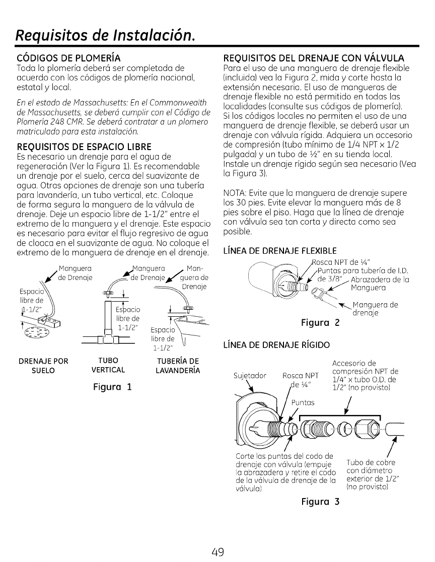
Requisitos de Instalaci6n.
C6DIGOS DE PLOMERIA
Toda la plomerfa deberci ser completada de
acuerdo con los c6digos de plomeria nacional,
estatal ylocal.
Enel estado de Massachusetts: Enel Commonwealth
de Massachusetts,se deberd cumplir con el Cddigo de
Plomerfa 248 CMR.Se deberd contratar a unplomero
matriculado para esta instalacidn.
REQUISITOS DE ESPACIO LIBRE
Esnecesario un drenaje para el agua de
regeneraci6n (Ver la Figura 1).Es recomendable
un drenaje par el suelo, cerca del suavizante de
agua. Otras opciones de drenaje son una tuberfa
para lavanderfa, un tuba vertical, etc. Coloque
de forma segura la manguera de la vcilvula de
drenaje. Deje un espacio libre de 1-1/2" entre el
extremo de la manguera y el drenaje. Este espacio
es necesario para evitar el flujo regresivo de agua
de cloaca en el suavizante de agua. No coloque el
extremo de la manguera de drenaje en el drenaje.
/Manguera _jvlanguera /Man-
_de Drenaje_/guera de
Espaci<de Drenaje _enaje
,ibrede \\ IIEsbar-l_ci°
DRENAJE PaR TUBa TUBERJA DE
SUELO VERTICAL LAVANDERJA
Figura i
REQUISITOS DEL DRENAJE CON V/_LVULA
Para el uso de una manguera de drenaje flexible
(incluida) yea la Figura 2, mida ycorte hasta la
extensi6n necesaria. Eluso de mangueras de
drenaje flexible no esta permitido en todas las
Iocalidades (consulte sus c6digos de plomerfa).
Si los c6digos locales no permiten el uso de una
manguera de drenaje flexible, se debera usar un
drenaje con valvula rfgida. Adquiera un accesorio
de compresi6n (tubo mfnimo de 1/4 NPTx 1/2
pulgada) yun tubo de ½" en su tienda local.
Instale un drenaje rfgido seg0n sea necesario (Vea
la Figura ]).
NOTA:Evite que la manguera de drenaje supere
los 30 pies. Evite elevar la manguera mas de 8
pies sabre el piso. Haga que la Ifnea de drenaje
con vdlvula sea tan corta ydirecta coma sea
posible.
LINEA DE DRENAJE FLEXIBLE
NPTde ¼"
para tuberfa de I.D.
3/8" _Abrazadera de la
, _ Nanguera
_-,, _r--_Manguerade
drenaje
Figura 2
LINEA DE DRENAJE RIGIDO
Accesoriode
compresi6nNPTde
Sujetador RoscaNPT i/4" × tuba O.D.de
_/de ¼" 1/2" (no
provisto)
,Puntas /
__tt_el codo de ?
drenajecon v(_Ivuk](empuje Tubode cobre
la abrazaderay retire elcodo condidmetro
dek] v61vulade drenajede k] exterior de i/2"
v_]vula) (noprovisto)
Figura 3
49
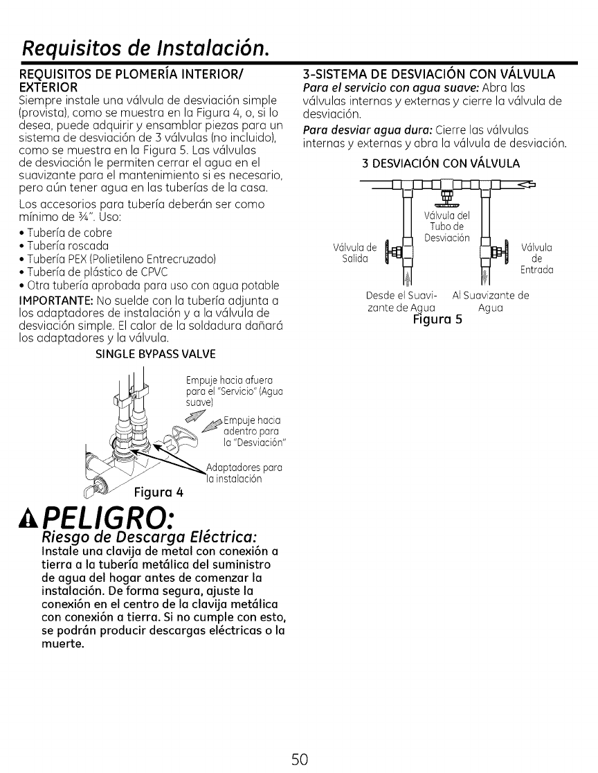
Requisitos de Instalaci6n.
REQUISITOS DE PLOMERJA INTERIOR/
EXTERIOR
Siempre instale una valvula de desviaci6n simple
(provista), coma se muestra en la Figura/4, o, si Io
desea, puede adquirir y ensamblar piezas para un
sistema de desviaci6n de 3 valvulas (no incluido),
coma se muestra en la Figura 5. Las valvulas
3-SISTEMA DE DESVIACION CON V/_LVULA
Para el servicio con agua suave: Abra las
valvulas internas y externas y cierre la valvula de
desviaci6n.
Para desviar agua dura: Cierre las vdlvulas
internas yexternas yabra la v61vula de desviaci6n.
de desviaci6n le permiten cerrar el agua en el
suavizante para el mantenimiento si es necesario,
pero aLin tener agua en las tuberfas de la casa.
Los accesorios para tuberfa debercin ser como
mfnimo de ¾". Uso:
• Tuberia de cobre
• Tuberia roscada
• Tuberia PEX(Polietileno Entrecruzado)
• Tuberia de pkistico de CPVC
• Otra tuberia aprobada para uso con agua potable
IMPORTANTE: No suelde con la tuberfa adjunta a
los adaptadores de instalaci6n y a la vcilvula de
desviaci6n simple. El calor de la soldadura dar_arci
los adaptadores y la vcilvula.
SINGLE BYPASSVALVE
3 DESVIACION CON V/_LVULA
V@lvulasalidade_vula
___ Entrada
Desde el Suavi- AI Suavizante de
zante de A_ua Agua
Rgura 5
_ Empujehacia afuera
para el "Servicio"(Agua
suave)
Empuje hacia
_adentro para
la "Desviaci6n"
Adaptadores para
la instalaci6n
_vJ_ Figura 4
,PELIGRO:
Riesgo de Descarga El_ctrica:
Instale una clavija de metal con conexi6n a
tierra a la tuberia met61ica del suministro
de agua del hogar antes de comenzar la
instalaci6n. De forma segura0 ajuste la
conexi6n en el centro de la clavija met61ica
con conexi6n a tierm. Si no cumple con esto0
se podr6n producir descargas el_ctricas o la
muerte.
5O
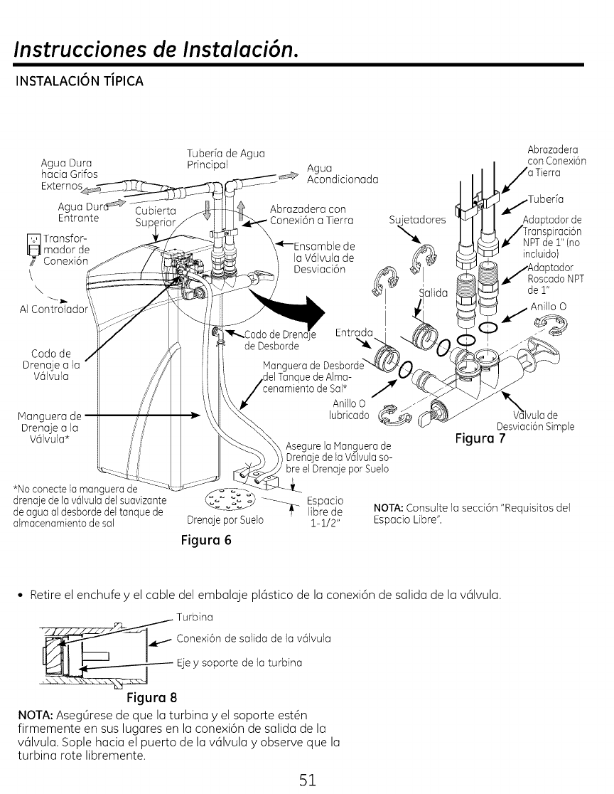
Instrucciones de Instalaci6n.
INSTALACIONTJPICA
Ague Dura
hada Grifos
E×ternos
Agua Dur_ Cubierta
Entrante Su
_ Transfor-
mador de
/// Conexi6n
\k
AI Controlado
Coda de
Drenoje a Io
V6lvula
Manguerade
Drenajeala
V61vula*
*No conecte la manguera de
drenaje de la valvula del suavizante
de agua al desborde del tanque de
almacenamiento de sal
TubeFa de Agua
Principal Ague
Acondicionada
Abrazadera
con Conexi6n
Tierra
Abrazadera con
Cone×i6n a Tierra
la V6lvula de
Desviaci6n
Su_dores
Asegurela languera de
Drenajede la V61vulasa-
breel Drenaje parSuelo
)iraci6n
NPTde 1" (no
incluido)
Dtador
RoscadoNPT
de 1"
Anfllo O
lvula de
Desviaci6nSimple
Figure 7
Espado
, libre de
Drenajepar Suelo 1-1/2"
Figure 6
NOTA:Consulte la secd6n "Requisitos del
Espado Libre".
• Retire el enchufe y el cable del embalaje pl6stico de la conexi6n de salida de la v61vula.
___- Turbine
Cone×i6ndesalida de la v61vula
Ejey soporte de la turbina
Figure 8
NOTA: Aseg0rese de que la turbina y el soporte est@n
firmemente en sus lugares en la conexi6n de salida de la
valvula. Sople hacia el puerto de la valvula y observe que la
turbina rote libremente.
51

Instrucciones de Instalaci6n.
ClERRE EL SUMINISTRO DE AGUA
1. Cierre lav61vuladel suministro principal de aguo, ubicada
cercade la bomba del pozo odel medidor de agua.
2. Abra todos los grifos pare drenar toda el ague de las tuberias
de la case.
NOTA:AsegOresede no drenar el ague del calentador de agua,
ya que esto podria ocasionar daBossabre los elementosdel
calentador de agua.
INSTALE EL CODO DE DESBORDE DEL
TANQUE DE SALMUERA
Instalelaarandelaaislantey elcodade desbordedel tanquede
salmueraen el agujerode 13/16" de di6metroen la parte trasera
de la paredlateral deltanquede almacenamientode sal;consulte
la Figura9
NOTA:Elcoda de desborde del tanque de salmuera acepta una
manguera I.D.de ½" o 3/8".
INSTALE LA V/_LVULA DE DESVIACION
NOTA:Pareuna instalaci6nf6cil,retire la tape superiorLiberelas
2 abrazaderasde la partetrasera de latapa Rotela tapa hacia
adelantey levantelamisma.
i Retiredosabrazaderasde las puertasde entraday salidade la
v61vuladelsuavizantedeagua y visualmentecontroley retire
cualquierescombro;consultela Figura7.
2 AsegOresede queel ensambledela turbinagire librementeen el
puerto de"salida"dela v61vula;consultela Figura8
3 SiaOnno serealiz6,coloqueuna coberturaluminosadegrasa
de siliconaen losanilloso dedesviaci6nsimple;consultela
Figura7.
4 Empujelav61vulade desviaci6nsimplesabrela v61vula
delsuavizantetanto comaseaposible Presionelasdos
abrazaderasdesujeci6nensus lugares,desdela parte superior
haciaabajo;consulte lasFiguras7 yi0
IMPORTANTE:AsegOresede que lasabrazaderasquedenfirmes,
de modoque lav61vulade desviaci6nsimpleno sesuelte
MUEVA EL SUAVIZANTE DE AGUA A SU LUGAR
iADVERTENCIA!
Riesgo de Peso Excesivo
Cuentecon la ayuda de dos o m6s personas
para mover e instalar el suavizante de agua. Si
esto no se hace,se podr6n producir lesionesde
espalda u otras lesiones.
1 Muevael suavizantede aguahastela ubicaci6ndeseada.
Coloqueelmismosabreuna superficies61iday nivelada
IMPORTANTE:NocoloquecuBasdirectamentedebajodeltanque
de almacenamientode sol pare nivelarel suavizante.Elpeso
@1tanque,cuandoest_Ilenode aguey sol,podr6 hacerquese
fractureen la cuba
52
Tape de
raSol
Ensomble
de Boquillo
Salmuera
Tanque
de Arma-
cenami-'_
ento de
Sal
Sujeci6n
raSalmuera
! Tuerco -
_'Abrazadera de
Refuerzo
.Agujero
1€_ Arandela
_islante
Co_o de
Desbordedel
Tanque de
Sarmuera
raSarmuera
Pozode
Salmuera
Figure 9 Hotaci6n
Note: La unidad se muestr a sin la tapa super ior..
V/_LVULA DE DESVIACION SIMPLE
Siseconectaala plomeriaa
niveldelsuelo,instalelav61vula
de desviaci6ngiradahacia
abajo,comasemuestra
ENSAMBLE CORRECTO
Abrazadera ._D,-_x ',z: _._ /
Di6metroexteriorde x,-Y__--'_L-/ Di6metro exterior del
canal de la abraza
entraday salidadela /" \ .
v61vuladelsuavizante/\ dora en la vatvula de
desviaci6n simple
deagua Figure 10
NOTA: AsegOrese de que las 3 lengOetas de la abrazadera
atraviesen los agujeros correspondientes en la entrada y salida
de la v61vula del suavizante de agua, y completamente en el
canal en la v6lvula de desviaci6n simple AsegOresede que las
lengQetas est@ncompletamente apoyadas
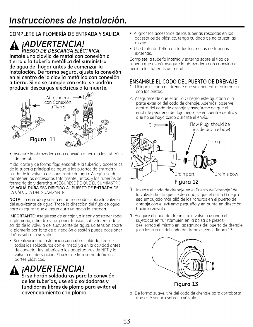
Instrucciones de Instalaci6n.
COMPLETELA PLOMERIADE ENTRADAY SALIDA
iADVERTENCIAJ
RIESGO DE DESCARGA ELECTRICA:
Inst(]le un(] clavij(] de metal con conexi6n (]
tierr(] (] I(] tuberi(] met61ic(] del suministro
de ague del hog(jr antes de comenz(]r I(]
inst(]l(]ci6n. De form(] segur(], (]juste I(] cone×i6n
en el centro de I(] cl(]vij(] met61ic(] con conexi6n
(] tierr(]. Si no se cumple con esto, se podr6n
producir descargas el_ctricas o la muerte.
• Asegure la abrazadera con conexi6n a tierra alas tuberfas
de metal.
Mida, carte y de forma fioja ensamble la tuberia y accesorios
de la tuberfa principal de agua a los puertos de entrada y
salida de la v6tvula del suavizante de agua. Aseg0rese de
mantener los accesodos totalmente juntos, y las tuberfas de
forma rigida yderecha. ASEGURESEDEOUEELSUMINISTRO
DEAGUA DURA SEADIRIGIDOAL PUERTODEENTRADADE
LAVALVULADELSUAVIZANTE.
NOTA:La entrada y salida est6n marcadas sabre la v61vula
del suavizante de agua. Trace la direcci6n del flujo de agua
para asegurar que el agua dura va hada la entrada.
IMPORTANTE:Aseg0rese de encajar, alinear y sostener toda
la plomeda, a fin de evitar poner tensi6n sabre la entrada y
salida de la v61vuladel suavizante de agua. La tensi6n sabre
la plomerfa par falta de alineaci6n o sost@npuede ocasionar
daFiossabre la vc_lvula.
• Si realizarc_una instalaci6n con cobre soldado, realice
todas las soldaduras con el metal ya en la cavidad antes
de conectar las tubedas a los adaptadores de NPTy la
v6tvula de desviaci6n. Elcator de la linterna dana las
partes pl6sticas.
iADVERTENCIA!
Si se h(]r_n soldadur(]s pare I(] conexi6n
de I(]s tuberi(]s, use s61o sold(]dor(]s y
fundidores libres de plomo pare evitar el
envenenamiento con plomo.
• AI girar los accesorios de las tuberias roscadas en los
accesorios de pl6stico, tenga cuidado de no cruzar las
roscas.
• Use Cinta de Tefl6n en todas las roscas de tuberias
externas.
Complete la tubeda interna yexterna sabre el tipo de
tuberia que usar6. Asegure la abrazadera con conexi6n a
tierra alas tubedas de metal.
ENSAMBLE EL CODO DEL PUERTO DE DRENAJE
1, Ubique el coda de drenaje que se encuentra en la balsa
con las piezas.
2. Aseg@esede que el anillo O negro est@ajustado ala
parte exterior del coda de drenaje. Ademc_s,observe
dentro del coda de drenaje yaseg0rese de que el
enchufe pequdio de flu]o negro se encuentre dentro y
que no se haya caido durante el envio.
Cli Flow Plug (should be
inside drain elbow)
'\Drain port Drain elbow
Figure 12
3. Inserte el coda de drenaje en el Puerto de "drenaje" de
la v61vulahasta que se detenga, y que el anillo O negro
sea empujado m6s altci de las ranuras en el puerto de
drenaje con el extremo pequeFioyen punta en direcci6n
hacia la v6lvula.
/4. Asegure el coda de drenaje ala v6lvula usando el
sujetador en "U" (tambi_n en la balsa de piezas),
deslizando el mismo en las ranuras del puerto de drenaje
y en los surcos del coda de drenaje (yea la figura 13).
Figura 13
5. De forma suave, tire del coda de drenaje para corroborar
que est@seguro sabre la v61vula.
53
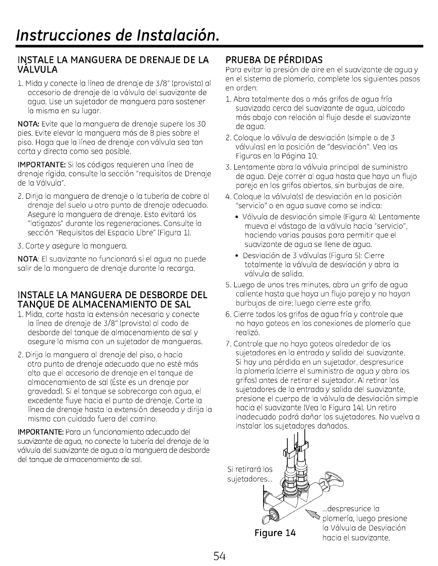
Instrucciones de Instalaci6n.
INSTALE LA MANGUERA DE DRENAJE DE LA
VALVULA
1. Mida yconecte la Ifnea de drenaje de 5/8" (provista) al
aceesorio de drenaje de la v@lvula del suavizante de
agua. Use un sujetador de manguera para sostener
la misma en su lugar.
NOTA: Evite que la manguera de drenaje supere los 50
pies. Evite elevar la manguera mds de 8 pies sobre el
piso. Haga que la I[nea de drenaje con v@lvulasea tan
corta ydirecta coma sea posible.
IMPORTANTE: Silos c6digos requieren una Ifnea de
drenaje rfgida, consulte la secei6n "requisitos de Drenaje
de la VSlvula".
2. DirUa la manguera de drenaje o la tubeda de cobre al
drenaje del suelo u otto punto de drenaje adecuado.
Asegure la manguera de drenaje. Esto evitara los
"latigazos" durante los regeneraciones. Consulte la
secci6n "Requisitos del Espacio Libre" (Figura 1).
5. Corte y asegure la manguera.
NOTA: Elsuavizante no funcionara si el agua no puede
salir de la manguera de drenaje durante la recarga.
INSTALE LA MANGUERA DE DESBORDE DEL
TANQUE DE ALMACENAMIENTO DE SAL
1. Mida, corte hasta Io extensi6n necesodo y conecte
la Ifnea de drenaje de 5/8" (provista) al codo de
desborde del tanque de almacenamiento de sal y
asegure la misma con un sujetador de mangueras.
2. Dirija la manguera al drenaje del piso, o hacia
otro punto de drenaje adecuado que no est6 m@s
alto que el accesorio de drenaje en el tanque de
almacenamiento de sal (_ste es un drenaje por
gravedad). Siel tanque se sobrecarga con agua, el
e×cedente fluye hacia el punto de drenaje. Corte la
linea de drenaje basra la extensi6n deseada ydirija la
misma con cuidado fuera del camino.
IMPORTANTE:Para un fundonamiento adecuado del
suavizante de agua, no conecte la tuberfa del drenaje de la
vSIvula del suavizante de agua a la manguera de desborde
del tanque de almacenamiento de sal.
PRUEBA DE PI_RDIDAS
Para evitar Japresi6n de aire en el suavizante de agua y
en el sistema de plomerfa, complete los siguientes pasos
en orden:
1. Abra totalmente dos o mds grifos de agua fr[a
suavizada cerca del suavizante de agua, ubicado
mds abajo con relaci6n al flujo desde el suavizante
de agua.
2. Coloque la v@lvula de desviaci6n (simple o de 3
valvulas) en la posici6n de "desviaci6n". Vea las
Figuras en la P@gina10.
3. Lentamente abra la v@lvula principal de suministro
de agua. Deje cotter al agua hasta que haya un flujo
parejo en los grifos abiertos, sin burbujas de aire.
/4.Coloque la v@lvula(s)de desviad6n en la posici6n
"servicio" o en agua suave coma se indica:
• V@lvulade desviaci6n simple (Figura/4): Lentamente
mueva el v@stago de la v@lvula hada "servicio",
hadendo varias pausas para permitir que el
suavizante de agua se Ilene de agua.
• Desviad6n de 3 v@lvulas (Figura 5): Cierre
totalmente la v@lvulade desviaci6n yabra la
v@lvulade salida.
5. Luego de unos tres minutes, abra un grifo de agua
caliente hasta que haya un flujo parejo yno hayan
burbujas de aire; luego cierre este gdfo.
6. Cierre todos los grifos de agua frfa ycontrole que
no haya goteos en las cone×iones de plomerfa que
realiz6.
7. Controle que no haya goteos alrededor de los
sujetadores en la entrada ysalida del suavizante.
Si hay una p@dida en un sujetador, despresurice
la plomeria (cierre el suministro de agua yabra los
grifos) antes de retirar el sujetador. AI retirar los
sujetadores de la entrada ysalida del suavizante,
presione el cuerpo de la v@lvula de desviaci6n simple
hacia el suavizante (Yea la Figura la,). Un retiro
inadecuado podr@da_ar los sujetadores. No vuelva a
instalar los sujetadores da_ados.
Si retirara los
sujetadores...
Figure 14
...despresurice la
plomerfa, luego presione
la V@lvulade Desviaci6n
hacia el suavizante.
54
Instrucciones de Instalaci6n.
AGREGUE AGUA Y SAL AL TANQUE DE
ALMACENAMIENTO DE SAL
iADVERTENCIA!
RIESGODE PESOEXCESIVO:
Cuente con la ayuda de dos o m6s
personas para mover e instalar las bolsas
de sal. Si esto no se cumple, se podr6n
producir lesiones de espalda u otras
lesiones.
1. Utilizando un envase, agregue alrededor de
tres galones de agua potable en el tanque de
almacenamiento de sal.
2. Agregue sal al tanque de almacenamiento. Use
pepitas, bolitas o sal solar gruesa con menos
del 1% de impurezas.
ENCHUFE EL SUAVIZANTE DE AGUA
1. Enchufe el suavizante de agua en un
tomacorriente el#ctrico que no est# controlado
por un interruptor.
2. Reemplace la tapa superior.
3. Reemplace la tapa del agujero de sal.
NOTA: El calentador de agua est6 Ileno con
agua dura y, a medida que se use agua caliente,
se volver6 a Ilenar con agua acondicionada.
En unos pocos dfas, el agua caliente estar6
completamente acondicionada. Para poder
contar con agua caliente acondicionada de forma
inmediata, espere hasta que la recarga inicial est#
terminada. Luego, drene el calentador de agua
(siguiendo instrucciones para el calentador de
agua), hasta que el agua se enfrfe.
DESINFECTE EL SUAVIZANTE DE AGUA/
DESINFECTE LUEGO DEL SERVICIO
1. Abra la tapa del agujero de sal, retire la tapa del
pozo de salmuera yvierLa alrededor de 3 oz. (6
cucharones) de blanqueador de hogar en el pozo
de salmuera del suavizante. Reemplace la tapa
del pozo de salmuera.
2. Aseg0rese de que la v61vula(s) de desviaci6n est_
en la posici6n de "servicio" (abierLa).
3. Comience una recarga (regeneraci6n). Consulte
"lniciar una Recarga" en la P6gina 13.
/4.Una vez completada la recarga, abra totalmente
un grifo de agua if[a, haga que corra el agua
desde el suavizante, y deje que 50 galones corran
a tray,s del sistema. Esto deber[a tomar por Io
menos 20 minutos. Cierre el grifo.
iADVERTENCIA! todos
los piezas sin uso y materiales de embalaje
luego de la instalaci6n. Los pequehas partes
restantes luego de la instalaci6n podrfan
ocasionar riesgo de obstrucci6n.
55
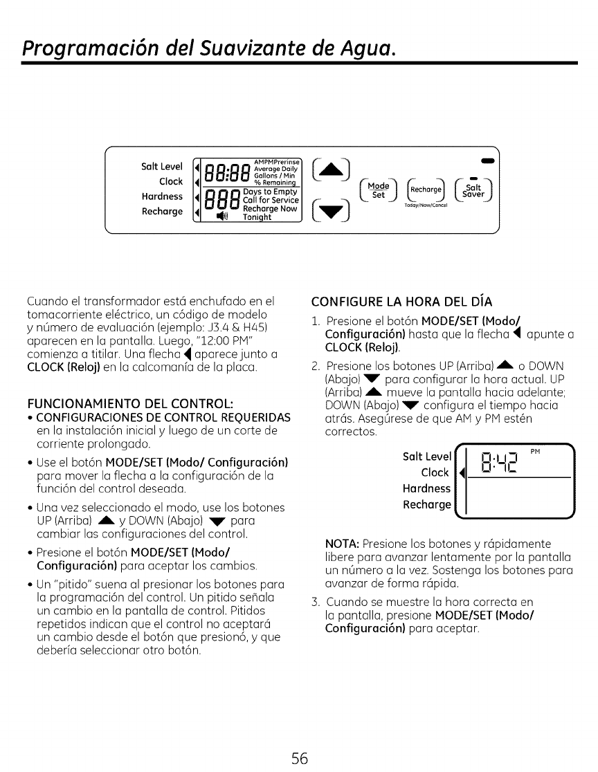
Programaci6n del Suavizante de Agua.
Salt Level
Clock
Hardness
Recharge
1 O1-]mlI-II-I GollonslMin I
I.... % Remaining I
I_ _ r'_ Days to Empty /
IHHHCa,,to,Service/
I_,a l.a _,a Recharge Now / _
,,,,Too,0 ,, Mo0e- i!) "
|. Set ..) char
Today/Now/Cancel
Cuando el transformador estci enchufado en el
tomacorriente el_ctrico, un c6digo de modelo
y nOmero de evaluaci6n (ejemplo: J3.4 & H45)
aparecen en la pantalla. Luego, "12:00 PM"
comienza a titilar. Una flecha _ aparecejunto a
CLOCK (Reloj) en la calcomanfa de la placa.
FUNCIONAMIENTO DEL CONTROL:
• CONFIGURACIONESDE CONTROL REQUERIDAS
en la instalaci6n initial y luego de un torte de
corriente prolongado.
°Use el bot6n MODE/SET (Modo/Configuraci6n)
para mover la flecha a la configuraci6n de la
funci6n del control deseada.
•Una vez seleccionado el modo, use los botones
UP(Arriba) Ak. y DOWN (Abajo) _lr para
cambiar las configuraciones del control.
•Presione el bot6n MODE/SET (Modo/
Configuraci6n) para aceptar los cambios.
•Un "pitido" suena al presionar los botones para
la programaci6n del control. Un pitido seSala
un cambio en la pantalla de control. Pitidos
repetidos indican que el control no aceptarci
un cambio desde el bot6n que presion6, yque
deberfa seleccionar otro bot6n.
CONFIGURE LA HORA DEL DJA
1. Presione el bot6n MODE/SET (Modo/
Configuraci6n) hasta que la flecha 4apunte a
CLOCK (Reloj).
2. Presione los botones UP(Arriba) A o DOWN
(Abajo) _r" para configurar la hora actual. UP
(Arriba) _L. mueve la pantalla hacia adelante;
DOWN (Abajo) _r" configura el tiempo hacia
atrcis. AsegOrese de que AM y PiVtest@n
correctos.
Salt Levelr
Clock I'
Hardness /
Recharge L
PH
Ft.1 i-I
L3"-iI- ]
NOTA: Presione los botones y rcipidamente
libere para avanzar lentamente por la pantalla
un nOmero a la vez. Sostenga los botones para
avanzar de forma rcipida.
3. Cuando se muestre la hora correcta en
la pantalla, presione MODE/SET IModo/
Configuraci6n) para aceptar.
56
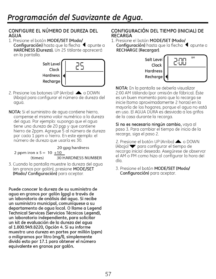
Programaci6n del Suavizante de Agua.
CONFIGURE EL NUMERO DE DUREZA DEL
AGUA
1. Presione el bot6n MODE/SET (Modal
Configuraci6n) hasta que la flecha _ apunte a
HARDNESS(Durezal. Un 25 titilante aparecer6
en la pantalla.
Salt Level j_ _-IJ- 1
Clock/ C 2! J
Hardness HI
Recharge (I
2. Presione los botones UP (Arriba) ,A_ o DOWN
(Abajo) para configurar el n0mero de dureza del
agua.
NOTA: Si el suministro de agua contiene hierro,
compense el mismo valor numGrico a la dureza
del agua. Por ejemplo: suponga que el agua
tiene una dureza de 20 pgp yque contiene
hierro de 2ppm. Agregue 5 al n0mero de dureza
por cada 1 ppm o hierro. En este ejemplo: el
n0mero de dureza que usarfa es 30.
20 gpg hardness
2ppmironx5= 10 +10
(times) 30 HARDNESS NUMBER
3. Cuando la pantalla muestre la dureza del agua
(en granos por gal6n), presione MODE/SET
(Modo/Configuraci6n) para aceptar.
CONFIGURACION DEL TIEMPO (INICIAL) DE
RECARGA
1. Presione el bot6n MODE/SET (Modo/
Configuraci6n) hasta que la flecha _ apunte a
I4 _-I.MM A. t
C.uu
Hardness
Recharge
RECHARGE (Recargar).
Salt Level
Clock
NOTA: En la pantalla se deberfa visualizar
2:00 AM titilando (por omisi6n de f6brica). Este
es un buen momento para que la recarga se
inicie (toma aproximadamente 2 horas) en la
mayorfa de los hogares, porque el agua no esta
en uso. ElAGUA DURA es desviada a los grifos
de la casa durante la recarga.
Si no es necesario ning0n cambio, vaya al
paso 3. Para cambiar el tiempo de inicio de la
recarga, siga el paso 2.
2. Presione el bot6n UP (Arriba) A o DOWN
(Abajo)_I r para configurar el tiempo de
recarga inicial deseado. Aseg0rese de observar
el AM o PiVtcomo hizo al configurar la hora del
dfa.
3. Presione el bot6n MODE/SET (Modo/
Configuraci6n) para aceptar.
Puede conocer la dureza de su suministro de
agua en granos por gal6n (gpg) a trav_s de
un laboratorio de an61isis del agua. Si recibe
un suministro municipal, comuniquese a su
departamento de agua local. 0 Ilame a Legend
Technical Services (Servicios T_cnicos Legend),
un laboratorio independiente, para solicitar
un kit de evaluaci6n de la dureza del agua
al 1.800.949.8220, Opci6n 4. Si su informe
muestra una dureza en partes por mill6n (ppm)
o miligramos por litro (mgll), simplemente
divida esto por 17.1 para obtener el nOmero
equivalente en granos por gal6n.
57
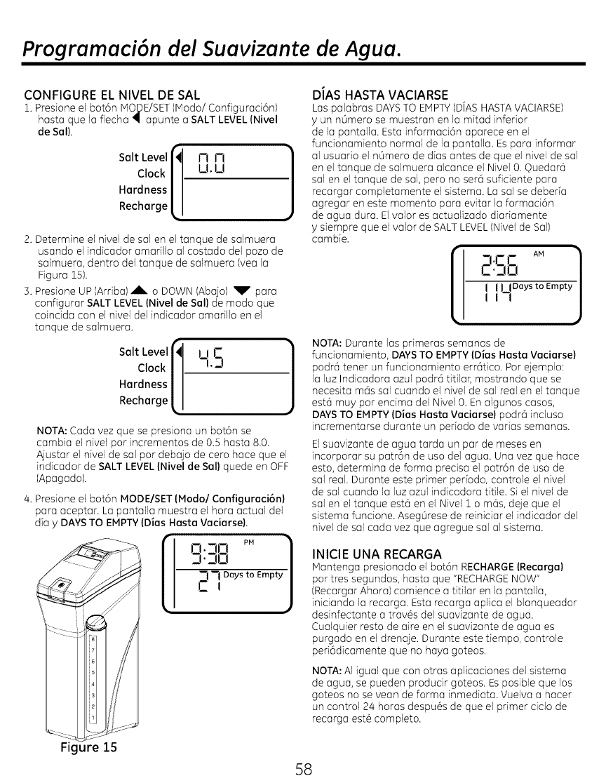
Programaci6n del Suavizante de Agua.
CONFIGURE EL NIVEL DE SAL
1. Presione el bot6n MODE/SET(IVlodo/Configuraci6n)
haste que la flecha • apunte a SALT LEVEL (Nivel
de Sel),
Hardness
Recharge
f
Salt Level I_ t-I l-i
Clock _ U. U
i
2. Determine el nivel de sal en el tanque de salmuera
usando el indicador amarillo al costado del pozo de
salmuera, dentro del tanque de salmuera (yea la
Figura 25).
3. Presione UP (Arriba) ,A, o DOWN (Abajo) _F" para
configurar SALT LEVEL(Nivel de Sel) de modo que
coincida con el nivel del indicador amarillo en el
tanque de salmuera.
I I J-Salt Level
Clock"/ -i.3
Hardness |
Recharge L'
NOTA: Cada vez que se presiona un bot6n se
cambia el nivel par incrementos de 0.5 haste 8.0.
Ajustar el nivel de sal par debajo de cero hace que el
indicador de SALT LEVEL (Nivel de Sel) quede en OFF
(Apagado).
4. Presione el bot6n MODE/SET (Modal Configuraci6n)
para aceptar. La pantalla muestra el hora actual del
die y DAYS TO EMPTY(Dies Haste Vaciarse).
.]..]Ci
"7 -1 Days to Empty
CI
Figure 15
D/AS HASTA VACIARSE
Las palabras DAYSTO EMPTY(DJASHASTAVACIARSE)
y un n6mero se muestran en la mitad inferior
de la pantalla. Esta informaci6n aparece en el
funcionamiento normal de la pantalla. Espara informar
al usuario el n6mero de alas antes de que el nivel de sal
en el tanque de salmuera alcance el Nivel 0. ©uedar6
sal en el tanque de sal, pero no ser6 suficiente para
recargar completamente el sistema. La sal se deberia
agregar en este momenta para evitar la formaci6n
de agua dura. El valor es actualizado diariamente
ysiempre que el valor de SALTLEVEL(Nivel de Sail
cambie.
-i.rr AM
r.. o _ _1
IILI°°yst°Emptyj
NOTA: Durante los primeras semanas de
funcionamiento, DAYSTO EMPTY(Dies Haste Vaciarse)
podr6 tenet un fundonamiento err6tico. Par ejemplo:
la luz Indicadora azul podr6 titilar, mostrando que se
necesita mc_ssal cuando el nivel de sal real en el tanque
est6 muy par endma del Nivel 0. En algunos casos,
DAYSTO EMPTY(Dies Haste Vecierse) podr(_ induso
incrementarse durante un peffodo de vadas semanas.
Elsuavizante de agua tarda un par de meses en
incorporar su patr6n de usa del agua. Una vez que hace
esto, determina de forma predsa el patr6n de usa de
sal real. Durante este primer perfodo, controle el nivel
de sal cuando la luz azul indicadora titile. Si el nivel de
sal en el tanque est6 en el Nivel 1 o m6s, deje que el
sistema funcione. Aseg0rese de reiniciar el indicador del
nivel de sal cada vez que agregue sal al sistema.
INICIE UNA RECARGA
Mantenga presionado el bot6n RECHARGE(Recarga)
par tres segundos, haste que "RECHARGENOW"
(Recargar Ahora) comience a titilar en la pantalla,
iniciando la recarga. Esta recarga aplica el blanqueador
desinfectante a trav6s del suavizante de agua.
Cualquier testa de aire en el suavizante de agua es
purgado en el drenaje. Durante este tiempo, controle
peri6dicamente que no haya goteos.
NOTA: AI igual que con otras aplicaciones del sistema
de agua, se pueden produdr goteos. Esposible que los
goteos no se vean de forma inmediata. Vuelva a hacer
un control 24 horas despu6s de que el primer ciclo de
recarga est6 completo.
$8
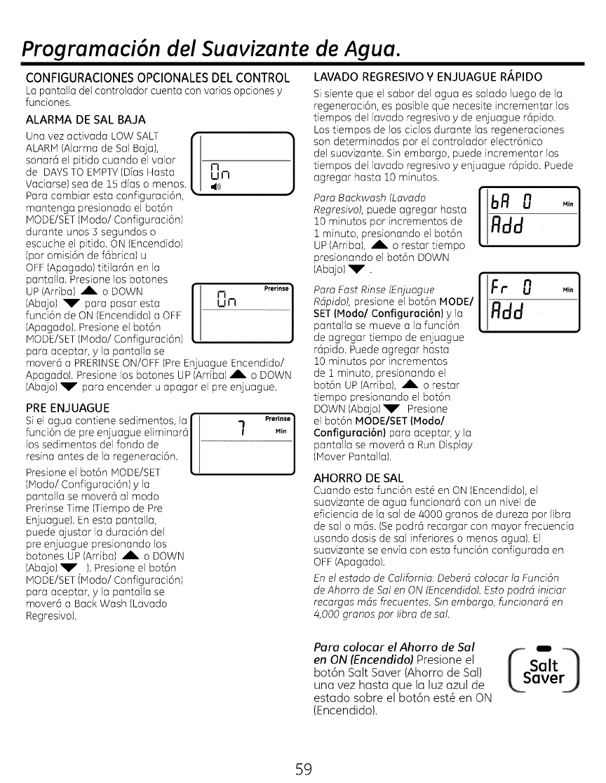
Programaci6n del Suavizante de Agua.
CONFIGURACIONESOPCIONALESDEL CONTROL
Lapantalladelcontroladorcuentaconvariasopcionesy
funciones.
ALARMA DE SAL BAJA
Una vez activada LOW SALT "_
ALARM(Alarma de Sal Baja), J
sonara el pitido cuando el valor J"l
de DAYSTO EMPTY(Dias Hasta U!-I
Vaciarse) sea de 15 dfas o menos. ,(_>)
Para cambiar esta configuraci6n, '
mantenga presionado el bot6n
MODE/SET(Modo/Configuraci6n)
durante unos S segundos o
escuche el pitido. ON (Encendido)
(par omisi6n de f@brica) u
OFF(Apagado) titilar@n en la
pantalla. Presione los botones
UP (Arriba) AL. o DOWN I'1 prerinse|
IAbajo) _T para pasar esta UN _
1
funci6n de ON (Encendido) a OFF
(Apagado). Presione el bot6n
MODE/SET(Modo! Configuraci6n) •
para aceptar, yla pantalla se
mover@ a PRERINSEON/OFF (Pre Enjuague Encendido/
Apagado). Presione los botones UP (Arriba) _, o DOWN
(Abajo) _r' para encender u apagar el pre enjuague.
PRE ENJUAGUE
Si el agua contiene sedimentos, la
funci6n de pre enjuague eliminar6
los sedimentos del fondo de
resina antes de la regeneraci6n.
Presione el bot6n MODE/SET
(Modo/Configuraci6n) y la
pantalla se mover6 al modo
Prerinse Time (Tiempo de Pre
Enjuague). En esta pantalla,
puede ajustar la duraci6n del
pre enjuague presionando los
botones UP (Arriba) ,_ o DOWN
(Abajo) _r' ).Presione el bot6n
MODE/SETiModo! Configuraci6n)
para aceptar, y la pantalla se
mover@ a Back Wash (Lavado
Regresivo).
Prerinse }
l MIn
LAVADO REGRESIVO Y ENJUAGUE R/_,PIDO
Si siente que el sabor del agua es salado Juego de la
regeneraci6n, es posible que necesite incrementar los
tiempos del lavado regresivo y de enjuague rapido.
Los tiempos de los cidos durante las regeneradones
son determinados par el controlador electr6nico
del suavizante. Sin embargo, puede incrementar los
tiempos del lavado regresivo y enjuague rapido. Puede
agregar hasta 10 minutos.
Para Backwash (Lavado
Regresivo), puede agregar hasta
10 minutos par incrementos de
1 minuto, presionando el bot6n
UP (Ardba), _L. o restar tiempo
presionando el bot6n DOWN
(Abajo) _r".
Para Fast Rinse (Enjuague
Rdpido), presione el bot6n MODEl
SET(Maria/Configuraci6n) y la
pantalla se mueve a la funci6n
de agregar tiempo de enjuague
rapido. Puede agregar basra
10 minutos par incrementos
de i minuto, presionando el
bot6n UP (Ardba), _L. o restar
tiempo presionando el bot6n
DOWN (Abajo)_r" Presione
el bot6n MODE/SET (Hodo/
Configuraci6n) para acepta4 y la
pantalla se movera a Run Display
(Mover Pantalla).
AHORRO DE SAL
Cuando esta funci6n est# en ON (Encendido), el
suavizante de agua funcionara con un nivel de
eficiencia de la sal de 4000 granos de dureza par libra
de sal o rods. (Se podra recargar con mayor frecuencia
usando dosis de sal inferiores o menos agua). El
suavizante se envia con esta funci6n configurada en
OFF(Apagado).
En el estado de California: Deberd eoloear la Funci6n
de Ahorro de Sol en ON (Encendido). Estopodrd iniciar
recargas mds #eeuentes. Sin embargo, funcionard en
4,000 granos par libra de sol.
Para colocar el Ahorro de Sol
en ON (Encendido) Presione el
bot6n Salt Saver (Ahorro de SaD
una vez hasta que la luz azul de
estado sabre el bot6n est@en ON
(Encendido).
59
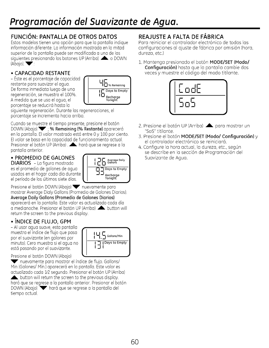
Programaci6n del Suavizante de Agua.
FUNCION: PANTALLA DE OTROS DATOS
Estosmodelostienen una opci6n para que la pantalla indique
informaci6n diferente. La informaci6n mostrada en la mitad
superior de la pantalla puede set modificada a una de los
siguientes presionando los botones UP (Arriba)Ab. o DOWN
(Abajo).'_V':
° CAPACIDAD RESTANTE
- Esteesel porcentaje de capacidad { I II-
restante para suavizarel agua. L-Ij-!O_oRomo_o_og/
De farina inmediata luegode una i C Daysto Empty/
regeneraci6n,se muestra el 100% ! U .
T_o_?h?e
A medida qua se usael agua,el )
porcentaje se reducir6 hasta la
siguiente regeneraci6n.Durante los regeneraciones,el
porcenta]ese incrementa hacia arriba.
Cuandose muestre el tiempo presente,presione el bot6n
DOWN(Aba]o)_V" ;% Remaining (% Restante)aparecerci
en la pantalla. El valor mostrado est6 entre 0 y 100 par ciento.
Elvalor se basaen la capacidad de funcionamiento actual.
Presionar el bot6n UP(Arriba). _b. har5 qua se regrese a la
pantalla anterior.
• PROMEDIO DE GALONES "_
DIARIOS - Lafigaro mostrada I _"_J"_,._lAverageDaiJYGaJJor_s
;
esel promedio de galones de agua 0 _1 Daysto Empty
usados en el hogar coda dia durante J __! _e_hgahrtge
el periodo de los 01timossiete dias.
Presioneel bot6n DOWN(Abajo)_P" nuevamente para
mostrar AverageDialy Gallons(Promediode Galones Diarios).
Average Daily Gallons (Promedio de GalonesDiarios)
apareeer6 en la pantalla. Estevalor es actualizado coda d[a
a medianoehe.Presionarel bot6n UP(Arriba) A button will
return the screen to the previous display.
• INDICE DE FLUJO, GPM
- AI usar agua suave, esta pantalla /
muestra el indice deflujo qua paso /
par el suavizante (en galones par I I--I.5 6att°ns/i_in
minuto).Ceromaestro si el agua no L I 7 I Daysto Empty
3!
estcipasando par el suavizante.
Presioneel bot6n DOWN(Abajo) ' ,_
_F" nuevamente para mostrar el indice de flujo. Gallons/
Hin (6alones/Hin.) aparecer0 en la pantalla. Estevalor es
actualizado coda 1/2segundo. Presionarel bot6n UP(Arriba)
Ab. button will return the screen to the previousdisplay.
hat6 qua se regrese a la pantalla anterior. Presionarel bot6n
DOWN(Abajo) _P" hare1qua se regresea la pantalla del
tiempo actual.
REAJUSTE A FALTA DE F/_BRICA
Parareiniciarelcontrolador electr6nicode todas los
configuracionesal ajuste def6brica par omisi6n(hora,
dureza,etc.)
i. Montengo presionodo el bot6n MODE/SET (Modal
Configuraci6n) hasta que la pantalla cambie dos
veces y muestre el c6digo delmodo titilante.
L- ]
OOC
i i
2. Presione el bot6n UP (Arriba) Ab. para mostrar un
"SOS"titilante.
5. Presione el bot6n MODE/SET (Modo/Configuraci6n) y
el controlador electr6nico se reiniciar@.
/4.Configure la hora actual, la dureza, etc., segOn
se describe en la secei6n de Programaci6n del
Suavizante de Agua.
6O
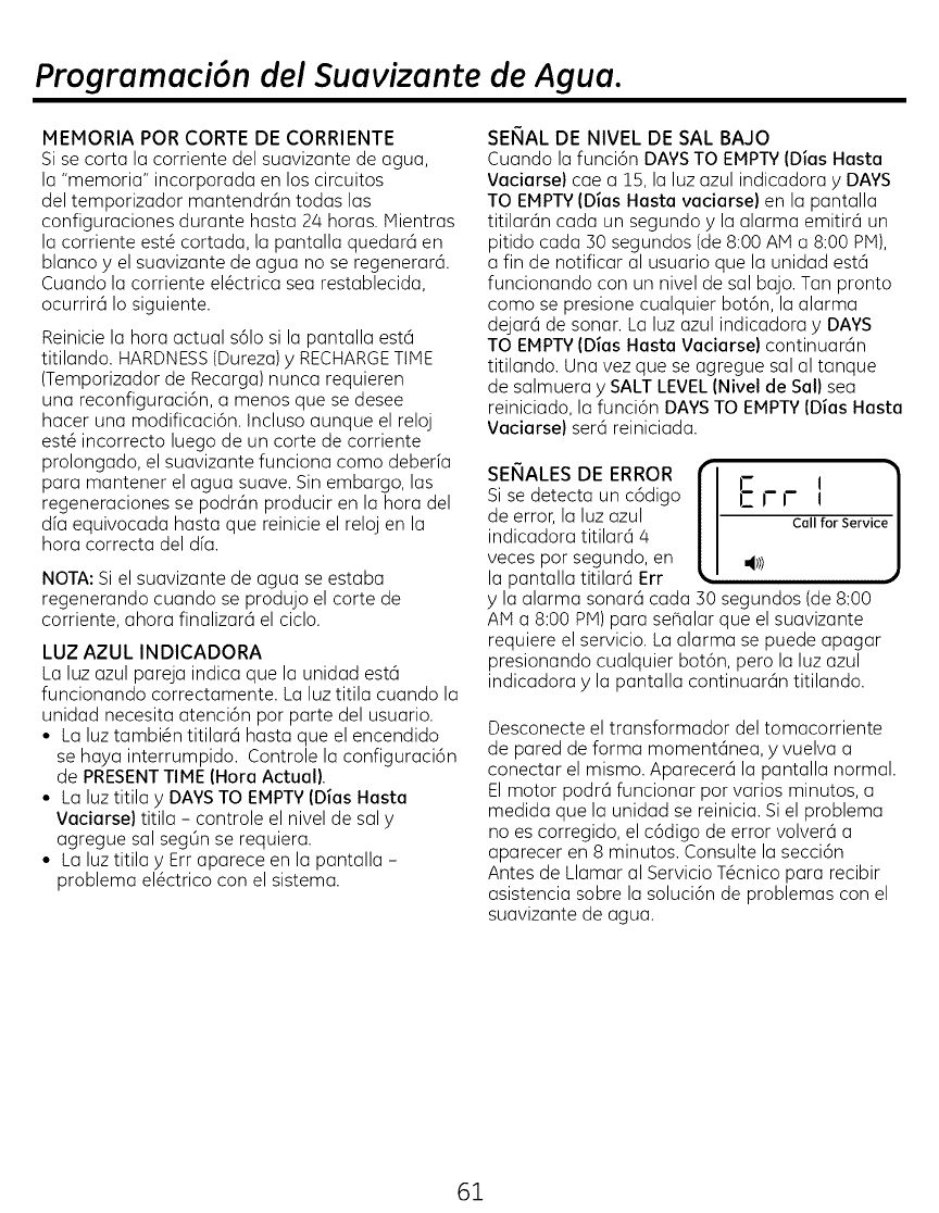
Programaci6n del Suavizante de Agua.
MEMORIA POR CORTE DE CORRIENTE
Si se corta la corriente del suavizante de agua,
la "memoria" incorporada en los circuitos
del temporizador mantendran todas los
configuraciones durante hasta 24 horas. Mientras
la corriente est_ cortado, la pantalla quedara en
blanco y el suavizante de agua no se regenerara.
Cuando la corriente el_ctrica sea restablecida,
ocurrira Io siguiente.
Reinicie la hora actual s61osi la pantalla esta
titilando. HARDNESS(Dureza)yRECHARGETIME
(Temporizador de Recarga) nunca requieren
una reconfiguraci6n, a menos que se desee
hacer una modificaci6n. Incluso aunque el reloj
est_ incorrecto luego de un corte de corriente
prolongado, el suavizante funciona como deber[a
para mantener el agua suave. Sin embargo, las
regeneraciones se podran producir en la hora del
dfa equivocada hasta que reinicie el reloj en la
hora correcta del d[a.
NOTA: Si el suavizante de agua se estaba
regenerando cuando se produjo el corte de
corriente, ahora finalizar6 el ciclo.
LUZ AZUL INDICADORA
La luz azul pareja inctica que la unidad esta
funcionando correctamente. La luz titila cuando la
unidad necesita atenci6n por parte del usuario.
• La luz tambi6n titilar6 hasta que el encendido
se haya interrumpido. Controle la configuraci6n
de PRESENTTIME (Hora Actual).
• La luz titila y DAYSTO EMPTY(Dias Hasta
Vaciarse) titila - controle el nivel de sal y
agregue sal seg0n se requiera.
• La luz titila yErr aparece en la pantalla -
problema el6ctrico con el sistema.
SENAL DE NIVEL DE SAL BAJO
Cuando la funci6n DAYSTO EMPTY(Dias Hasta
Vaciarse) cae a 15, la luz azul indicadora yDAYS
TO EMPTYIDias Hasta vaciarse) en la pantalla
titilar6n cada un segundo y la alarma emitir6 un
pitido cada 30 segundos (de 8:00 AM a 8:00 pivt),
a fin de notificar al usuario que la unidad estci
funcionando con un nivel de sal bajo. Tan pronto
como se presione cualquier bot6n, la alarma
dejarci de sonar. La luz azul indicadora y DAYS
TO EMPTYIDias Hasta Vaciarse) continuarc]n
titilando. Una vez que se agregue sal al tanque
de salmuera ySALT LEVEL(Nivel de Sal) sea
reiniciado, la funci6n DAYSTO EMPTY(Dias Hasta
Vaciarse) sera reiniciada. ( j
SENALES DE ERROR i- I
Si se detecta un c6digo _ I" I- I
de error, la luz azul Call for Service
indicadora titilar6 4
veces por segundo, en ,€1)
la pantalla titilar6 Err
yla alarma sonarci cada 30 segundos (de 8:00
AM a 8:00 PiVl)para se_alar que el suavizante
requiere el servicio. La alarma se puede apagar
presionando cualquier bot6n, pero la luz azul
indicadora yla pantalla continuar6n titilando.
Desconecte el transformador del tomacorriente
de pared de forma momentcinea, yvuelva a
conectar el mismo. Aparecerci la pantalla normal.
El motor podrci funcionar por varios minutos, a
medida que la unidad se reinicia. Siel problema
no es corregido, el c6digo de error volverci a
aparecer en 8 minutos. Consulte la secci6n
Antes de Llamar al Servicio T6cnico para recibir
asistencia sobre la soluci6n de problemas con el
suavizante de agua.
61
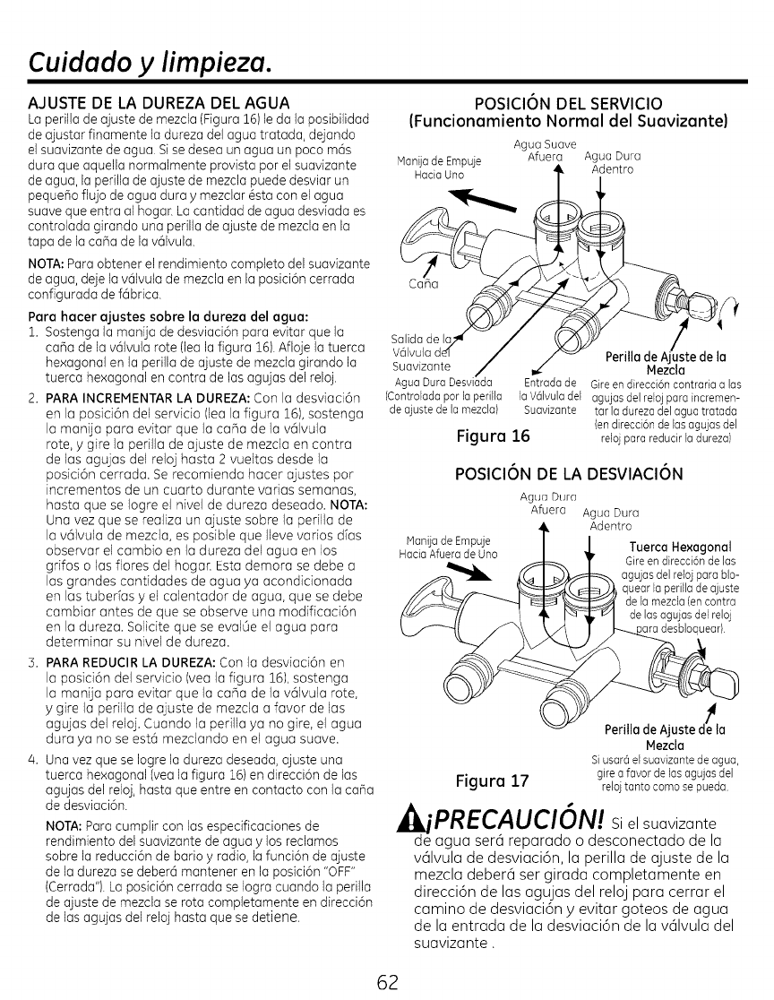
Cuidado ylimpieza.
AJUSTE DE LA DUREZA DEL AGUA
La perilla de ajuste de mezcla (Figura 16)le da la posibilidad
de ajustar finamente la dureza del agua tratada, dejando
el suavizante de agua. Sise desea un agua un poco m6s
dura que aquella normalmente provista par el suavizante
de agua, la perilla de ajuste de mezcla puede desviar un
peque_o flujo de agua dura ymezclar @stacon el agua
suave que entra al hogan La cantidad de agua desviada es
controlada girando una perilla de ajuste de mezcla enla
tapa de la ca_a de la v61vula.
NOTA:Para obtener el rendimiento completo del suavizante
de agua, deje la v61vula de mezcla en la posici6n cerrada
configurada de f6brica.
Pare hacer ajustes sobre la dureza del ague:
1. Sostenga la manija de desviaci6n para evitar que la
ca_a de la v61vularote (lea la figura 16).Afloje la tuerca
hexagonal en la perilla de ajuste de mezcla girando la
tuerca hexagonal en contra de las agujas del reloj.
2. PARA INCREMENTARLA DUREZA: Con la desviad6n
en la posici6n del servicio (lea la figura 16),sostenga
la manija para evitar que la ca_a de la valvula
rote, ygire la perilla de ajuste de mezcla en contra
de las agujas del reloj hasta 2 vueltas desde la
posici6n cerrada. Se recomienda hacer ajustes pot
incrementos de un cuarto durante varias semanas,
hasta que se Iogre el nivel de dureza deseado. NOTA:
Una vez que se realiza un ajuste sobre la perilla de
la v61vula de mezcla, es posible que Ileve varios dias
observar el cambio en la dureza del agua en los
grifos o las flores del hogar. Esta demora se debe a
las grandes cantidades de agua ya acondidonada
en las tuberias yel calentador de agua, que se debe
cambiar antes de que se observe una modificaci6n
en la dureza. Solicite que se evalOe el agua para
determinar su nivel de dureza.
3. PARAREDUCIR LA DUREZA: Con la desviad6n en
la posid6n del servicio (yea la figura 161,sostenga
la manija para evitar que la carla de la valvula rote,
ygire la perilla de ajuste de mezcla a favor de las
agujas del reloj. Cuando la perilla ya no gire, el agua
dura ya no se est6 mezdando en el agua suave.
4. Una vez que se Iogre la dureza deseada, ajuste una
tuerca hexagonal (yea la figura 16)en direcci6n de las
agujas del reloj, hasta que entre en contacto con la ca_a
de desviaci6n.
NOTA: Para cumplir con las especificaciones de
rendimiento del suavizante de agua ylos reclamos
sabre la reducci6n de bario y radio, la funci6n de ajuste
de la dureza se deber6 mantener en la posici6n "OFF"
(Cerrada"). La posici6n cerrada se Iogra cuando la perilla
de ajuste de mezcla se rata completamente en direcci6n
de las agujas del reloj hasta que se detiene.
POSICION DEL SERVICIO
(Funcionamiento Normal del Suavizante}
Agua Suave
Hanija de Empuje Afuera Agua Dura
Hacia Uno Adentro
Cana
sali
v61vula
suavizante f
AguaDuraDeswada Entradade
(Controladaporla perilla laV6lvuladel
deajustedelamezcla) Suavizante
Figura 16
Perilla de la
Mezcla
Gireendirecci6ncontrariaalas
agujasdelrelojparaincremen-
tarJadurezadeJaguatratada
(endirecci6nde lasagujasdel
relojparareducirladureza)
POSlClON DE LA DESVIAClON
Agua Durn
Afuera
Hanijade Empuje
HaciaAfueradeUno
Figure 17
Agua Dura
Adentro
Tuerca Hexagonal
Gire en direcci6n de las
_-_-.agujasdelrelojparablo-
quearlaperilladeajuste
de lamezda(encontra
r" I delasagujasdelreloj
//I-__._esbioq uear,
Perilla de Ajuste d_la
Mezcla
Siusar6elsuavizantedeagua,
girea favordelasagujasdel
relo] tantocomose pueda
iPRECAUCIC)N! Si el suavizante
de agua ser@reparado o desconectado de la
valvula de desviaci6n, la perilla de ajuste de la
mezcla deber6 ser girada completamente en
direcci6n de las agujas del reloj para cerrar el
camino de desviaci6n y evitar goteos de agua
de la entrada de la desviaci6n de la valvula del
suavizante.
62
Cuidado ylimpieza.
CONTROL DEL NIVEL DE ALMACENAMIENTO
DE SAL yRECARGA
La salmuera (sal disuelta en agua) es necesaria
en cada recarga. Elagua para hacer salmuera
es medida en el 6rea de almacenamiento de sal
por la v61vula del sistema suavizante de agua y
el control. Sin embargo, se deber4 mantener el
tanque suministrado con sal.
AGREGADODE SAL
Levante la tapa del agujero de sal y controle
el nivel de almacenamiento de sal de forma
frecuente. Si el suavizante de agua usa toda la
sal antes de recargar la misma, obtendra agua
dura. Hasta que haya establecido una rutina de
recarga, controle la sal cada dos o tres semanas.
Siempre agregue sal cuando la cantidad sea
inferior a ¼. Aseg0rese de que la tapa del pozo de
salmuera est@colocada.
NOTA: Si usar6 cloruro de potasio (KCI),no supere
el nivel 4 de la etiqueta del pozo de salmuera.
NOTA: En 6reas h0medas, es mejor mantener
el nivel de almacenamiento de sal bajo, y hacer
recargas m6s frecuentes para evitar "puentes" de
sal.
Sel Recomendede: Pepitas, bolitas o sal solar
gruesa con menos del 1% de impurezas.
Sal No Recomendede: Sal en roca, alta en
impurezas, en bloque, granulada de mesa,
derretida en hielo, para hacer helado, etc.
_]I_PRECAUCION:
Sal pare suavizante de ague con
aditivos pare eliminar hierro:
Algunas sales cuentan con un aditivo pare
ayudar al sistema suavizante de ague a
eliminar el hierro del suministro de ague.
Aunque este aditivo puede ayudar a mantener
limpia la resina del sistema suavizante de
ague, tambi_n puede liberar gases corrosivos
que debilitan y acortan la vide 5til de algunas
partes del sistema suavizante de ague.
LIHPIEZA DEL HIERRO DEL SISTEMA
SUAVIZANTE DE AGUA
Su sistema suavizante de agua elimina los
minerales duros (calcio y magnesio) del agua.
Adem6s, puede controlar parte (lea la secci6n
de Pautas de Especificaci6n) del hierro del "agua
potable". Con el hierro del agua potable, el agua
de un grifo es potable cuando se coloca por
primera vez en un vaso. Luego de entre 15 y30
minutos, el agua comienza a enturbiarse o tomar
un color 6xido. Un sistema suavizante de agua
no eliminard ning0n hierro que enturbie el agua
o la oxide al salir del grifo (llamado hierro de
agua roja), para quitar el hierro del agua roja del
agua, o el maximo de hierro del agua potable, es
necesario un filtro de hierro u otro equipamiento.
Si el suministro de agua posee hierro en el agua
potable, es necesaria una limpieza peri6dica
del fondo de resina. GE recomienda el uso de la
marca de limpiador de fondo de resina Super Iron
Out@ para limpiar completamente el fondo de
resina si el contenido de hierro es alto. Limpie el
fondo por Io menos cada seis meses, o con mayor
frecuencia si el hierro aparece en el agua suave
entre las limpiezas.
IMPORTANTE: Es importante mezclar el limpiador
del fondo de resina con agua (siguiendo las
instrucciones del fabricante), verter la misma en
el pozo de selmuere (yea la Figura 9)y recargar
el suavizante de forma inmediata. No vierta el
limpiador del fondo de resina con la sal, ya que
no sere tan efectivo en la limpieza de la resina, y
podra ocasionar dar_os al suavizante si se deja en
el tanque de salmuera por un perfodo extendido
debido a los gases corrosivos que se forman.
63
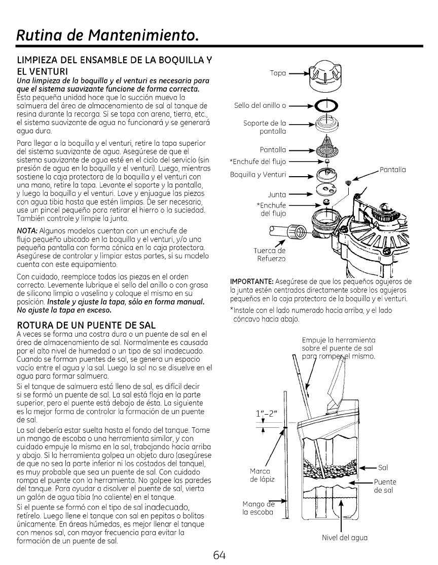
Rutina de Mantenimiento.
LIMPIEZA DEL ENSAMBLE DE LA BOQUILLA Y
EL VENTURI
Una limpieza de la boquilla yel venturi es necesaria para
que el sistema suavizante funcione de forma correcta.
Esta peque_a unidad hace que la succi6n mueva la
salmuera del 6rea de almacenamiento de sal al tanque de
resina durante la recarga. Si se tapa con arena, tierra, etc.,
el sistema suavizante de agua no funcionar6 y se generar6
agua dura.
Para Ilegar a la boquilla y el venturi, retire la tapa superior
del sistema suavizante de agua. Aseg0rese de que el
sistema suavizante de agua est@en el ciclo del servicio (sin
presi6n de agua en la boquilla y el venturi). Luego, mientras
sostiene la caja protectora de la boquilla y el venturi con
una mano, retire la tapa. Levante el soporte y la pantalla,
y luego la boquilla y el venturi. Lave y enjuague las piezas
con agua tibia hasta que est@nlimpias. De set necesario,
use un pincel pequeBo para retirar el hierro o la suciedad.
Tambi_n controle y limpie la junta.
NOTA;AIgunos modelos cuentan con un enchufe de
flu]o pequeBo ubicado en la boquilla y el venturi, y/o una
peque_a pantalla con forma c6nica en la caja protectora.
Aseg0rese de controlar y limpiar estas partes, si su modelo
cuenta con este equipamiento.
Con cuidado, reemplace todas las piezas en el arden
correcto. Levemente lubrique el sello del anillo o con grasa
de silicona limpia o vaselina y coloque el mismo en su
posici6n. Instale y aluste la tapa, s61oen farina manual.
No ajuste la tapa en exceso.
ROTURA DE UN PUENTE DE SAL
A veces se forma una costra dura o un puente de sal en el
6rea de almacenamiento de sal. Normalmente es causada
por el alto nivel de humedad o un tipo de sal inadecuado.
Cuando se forman puentes de sal, se genera un espacio
vado entre el agua y la sal. Luego la sal no se disuelve en el
agua para formar salmuera.
Si el tanque de salmuera est6 Ileno de sal, es dificil deck
si se form6 un puente de sal. La sal est6 floja en la parte
superior, pero el puente est6 debajo de @sta.La siguiente
es la mejor forma de controlar la formaci6n de un puente
de sal.
La sal deber[a estar suelta hasta el fondo del tanque. Tome
un mango de escoba o una herramienta similar, y con
cuidado empuje la misma en la sal, trabajando hacia arriba
y abajo. Si la herramienta golpea un objeto duro (aseg0rese
de que no sea la parte inferior ni los costados del tanque),
es muy probable que sea un puente de sal. Con cuidado
rompa el puente con la herramienta. No golpee las paredes
del tanque. Para ayudar a disolver el puente de sal, vierta
un gal6n de agua tibia (no caliente) en el tanque.
Si el puente se form6 con el tipo de sal inadecuado,
ret[relo. Luego Ilene el tanque con sal en pepitas o bolitas
0nicamente. En 6reas h0medas, es mejor Ilenar el tanque
con menos sal,con mayor frecuencia para evitar la
formaci6n de un puente de sal.
64
Tapa --_
Sellodel anilto o ---l_'_l
/
Soporte de la --_._(_]
pantatla
Pantalla --._.
*Enchufe del fiujo _,
Boquitlay Venturi _
Junta
*Enchufe _
del flujo
_...._ Pantatla
Tuerca d'_e
Refuerzo
IMPORTANTE: AsegOrese de que lospeque_os agujerosde
lajuntaest@n centradosdirectamentesobre losagujeros
peque_os en lacajaprotectorade laboquillayelventuri.
*lnstale con el lado numerado hacia arriba, y el lado
c6ncavo hacia abajo.
Empuje la herramienta
sobre el puente de sal
fl mismo.
Marca
de 16piz
Mango cT_-_
loescoba
Jente
de sat
Nivel del agua
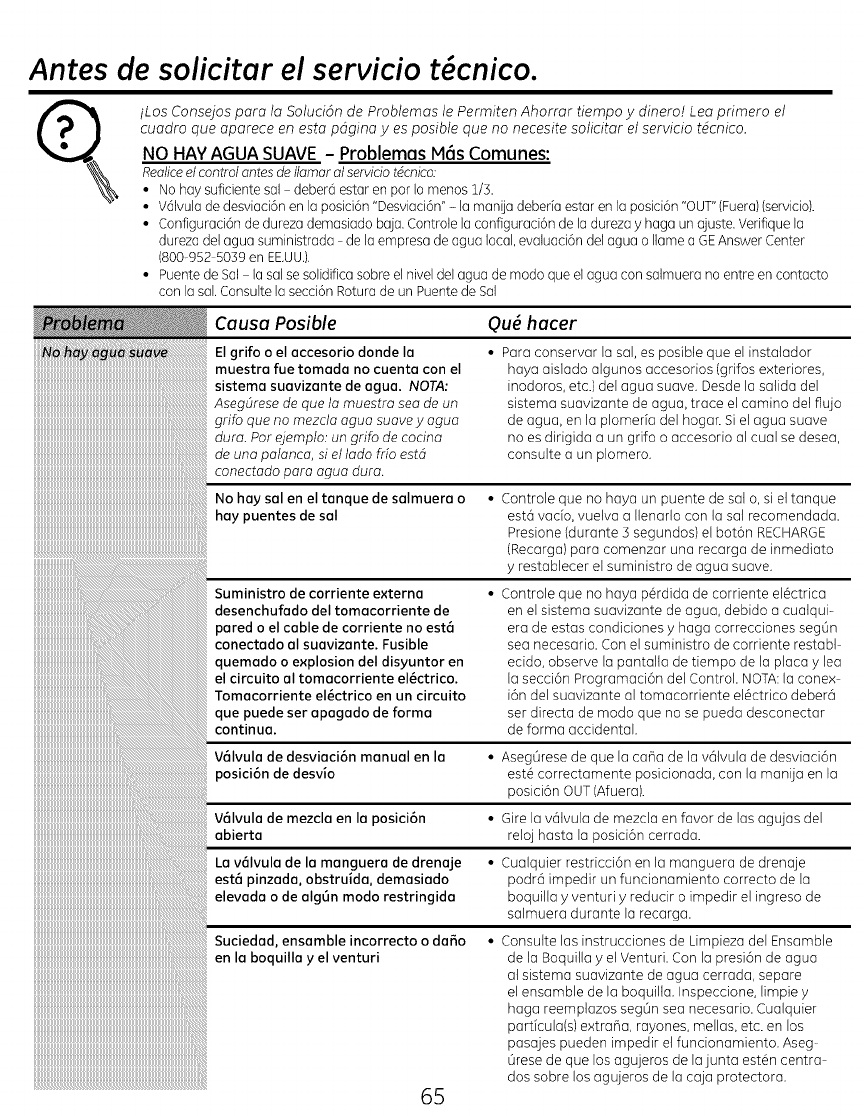
Antes de solicitar el servicio t cnico.
iLos Consejos para la Soluci6n de Problemas le Permiten Ahorrar tiempo ydinero! Lea primero el
cuadro que aparece en esta pdgina yes posible que no necesite solicitar el servicio tdcnico.
NO HAY AGUA SUAVE - Problemas M6s Comunes:
Realiceel controlantesdeIlamaral serviciotdcnico:
• No hay suficientesal deber6 estar en por Io menos1/S.
• V@ivulade desviaci6nen la posici6n"Desviaci6n"- la manUadeberiaestaren la posici6n"OUT"(Fuera)(servicio).
• Coafiguraci6nde durezademasiado baja.Controlela coafiguraci6nde la durezay haga un ajuste,verifique la
durezadelagua suministrada delaempresade agua local,evatuaci6adelagua o llame aGEAnswerCenter
(800-%2 5039en EEUU.).
• Puentede Sal la sal sesolidificasobreel niveldelagua de modo que el agua consaimuera no entre en contacto
con lasak Consultela secci6nRoturade un Puentede Sal
mmmmmmmmmmmmmmmmmmmmmmmmmmmmmmmmmmmm,_
mmmmmmmmmmmmmmmmmmmmmmmmmmmmmmmmmmmm_,_
mmmmmmmmmmmmmmmmmmmmmmmmmmmmmmmmmmmmm_
mmmmmmmmmmmmmmmmmmmmmmmmmmmmmmmmmmmmm,_
mmmmmmmmmmmmmmmmmmmmmmmmmmmmmmmmmmmmm_,_
mmmmmmmmmmmmmmmmmmmmmmmmmmmmmmmmmmmmmm_
mmmmmmmmmmmmmmmmmmmmmmmmmmmmmmmmmmmmmm,_
mmmmmmmmmmmmmmmmmmmmmmmmmmmmmmmmmmmmmm_,_
mmmmmmmmmmmmmmmmmmmmmmmmmmmmmmmmmmmmmmm_
______________________________________________________________________________________________________________________i
Causa Posible C2u_hacer
El grifo o el accesorio donde la
muestra fue tomada no cuenta con el
sistema suavizante de agua. NOTA:
AsegOrese de que la muestra sea de un
grifo que no mezcla agua suave y agua
dura. Par ejemplo: un grifo de cocina
de una palanca, si el lado frio estd
conectado para agua dura.
No hay sal en el tanque de salmuera o
hay puentes de saI
Suministro de corriente externa
desenchufado deI tomacorriente de
pared o el cable de corriente no est6
conectado aI suavizante. Fusible
quemado o explosion deI disyuntor en
el circuito aI tomacorriente el_ctrico.
Tomacorriente eI_ctrico en un circuito
que puede ser apagado de forma
continua.
• Para conservar la sal, es posible que el instalador
haya aislado algunos accesorios (grifos exteriores,
inodoros, etc.) del agua suave. Desde la saiida del
sistema suavizante deagua, trace el camino del flujo
de agua, en la plomeria del hogar. Siel agua suave
no es dirigida a un grifo o accesorio al cual se desea,
consulte a un plomero.
• Controle que no haya un puente de sal o, si el tanque
est6 vacio, vuelva a Ilenarla con la sat recomendada.
Presione (durante 3 segundos) el bot6n RECHARGE
(Recarga) para comenzar una recarga de inmediato
y restablecer el suministro de agua suave.
• Controle que no haya p@dida de corriente el@ctrica
en el sistema suavizante de agua, debido a cuatqui-
era de estas condiciones yhaga correcciones segQn
sea necesario. Con el suministro de corriente restabl
ecido, observe la pantalta de tiempo de la placa y lea
la secci6n Pragramaci6n del Control. NOTA: la cortex
i6n del suavizante al tamacomente el@ctrico deber6
ser directa de modo que no se pueda desconectar
de forma accidental.
V61vula de desviaci6n manual en la
posici6n de desvio
V6Ivula de mezclaen Ia posici6n
abierta
La v61vula de la manguera de drenaje
est6 pinzada, abstruida, demasiado
elevada o de alg_n modo restringida
Suciedad, ensamble incorrecto o dafio
en laboquilla y el venturi
mmmmmmmmmmmmmmmmmmmmmmmmmmmmmmmmmmm,
mmmmmmmmmmmmmmmmmmmmmmmmmmmmmmmmmmm_,
mmmmmmmmmmmmmmmmmmmmmmmmmmmmmmmmmmmm
mmmmmmmmmmmmmmmmmmmmmmmmmmmmmmmmmmmm,
mmmmmmmmmmmmmmmmmmmmmmmmmmmmmmmmmmmm_,
mmmmmmmmmmmmmmmmmmmmmmmmmmmmmmmmmmmmm
mmmmmmmmmmmmmmmmmmmmmmmmmmmmmmmmmmmmm,
mmmmmmmmmmmmmmmmmmmmmmmmmmmmmmmmmmmmm_,
mmmmmmmmmmmmmmmmmmmmmmmmmmmmmmmmmmmmmm
mmmmmmmmmmmmmmmmmmmmmmmmmmmmmmmmmmmmmm,
mmmmmmmmmmmmmmmmmmmmmmmmmmmmmmmmmmmmmm_,
mmmmmmmmmmmmmmmmmmmmmmmmmmmmmmmmmmmmmmm
______________________________________________________________________________________________________________________i
65
• AsegQrese de que la cdia de la v6tvula de desviaci6n
est@carrectamente posicionada, can la manUa en la
posici6n OUT (Afuera).
• Gire la v61vulade mezcla en favor de las agujas del
reloj hasta la posici6n cerrada.
• Cualquier restricd6n en la manguera de drena]e
podr@impedir un funcionamiento correcto de la
boquilla y venturi y reducir o impedir el ingreso de
salmuera durante la recarga.
• Consutte las instrucciones de Limpieza del Ensamble
de la Boquilla y el Venturi. Con la presi6n de agua
al sistema suavizante de agua cerrada, separe
el ensamble de la boquilla. Inspecdone, limpie y
haga reemplazos segOn sea necesario. Cualquier
particula(s) extraBa, rayones, mellas, etc. en los
pasajes pueden impedir et funcionamiento, Aseg-
Orese de que los agujeros de la junta est@n centra
dos sobre los agujeros de la caja protectora.
Antes de solicitar el servicio t cnico.
Causa Posible Ou_ hacer
Uso de agua caliente mientras el
sistema suavizante de agua se est6
regenerando
Configuraci6n del n6mero de control
de DUREZA demasiado bajo
Los granos de dureza en el suministro
de agua se incrementaron
•Evite usar agua caliente durante la recarga det
sistema suavizante de agua, ya que el calentador
de agua se volver6 a Ilenar con agua dura. Consulte
la secci6n de Desviaci6n del Agua Dura Durante la
Recarga
• Presione el bot6n MODE/SET (Modo/Configuraci6n)
hasta que la flecha senale hacia HARDNESS (Dureza).
Aseg0rese de que el n0mero mostrado sea el mismo
que aquel de la dureza de granos por gal6n real de
su suministro de agua. En caso de ser necesario
un cambio en la configuraci6n, consulte la secci6n
Programaci6n del Control.
• La dureza del agua puede cambiar con et paso del
tiempo, especialmente con agua de pozo. Para
controlar esto, solicite que el agua sea evaluada
a trav@sde un an6tisis de laboratorio o Ilame a su
departamento de abastecimiento de agua local,
Ajuste la configuraci6n del n0mero de Dureza seg0n
sea necesario.
Ausencia de minerales con dureza • Esto es normal. La dureza del agua le da una sen
saci6n abrasiva a la cual usted se pudo haber acos
tumbrado. La sensaci6n resbatosa es la sensaci6n
pura del agua suave.
•Consulte la secd6n Ajuste de la Dureza del Agua.
El sistema suavizente de ague es una • No utiliza mocha sal para la regenerad6n muy
unidad de "dementia" eficiente.
Posible puente de sal • Consulte la secd6n Rotura de un Puente de Sat.
Posible atescemiento de le boquilla y • Consutte la secci6n Limpieza del Ensamble de la
el venturi Boquitla y el Venturi
Ague 6cida en Ia plomeria de cobre • Solicite que el agua sea evaluada de inmediato.
Atascamiento deI contador de Ia • Para realizar los procedimientos de soluci6n de
turbine problemas, consulte la secci6n de Diagn6stico de
Componentes Electr6nicos Iniciados iV]anualmente.
• Llame at servicio t_cnico,
Cable del sensor no enchufodo en el • Para realizar los procedimientos de soluci6n de
control problemas, consulte la secci6n de Diagn6stico de
Componentes Electr6nicos Iniciados iV]anualmente.
• Llame at servicio t@cnico.
No hay corriente en Ia unidad • Controle el disyuntor o los fusibles..
Defecto mec6nico • Llame at servicio t@cnico.
Combinaci6n de agua suave y dema-
siado detergente
•Estose llama aguafuerte y es permanente, Para evi
tar que esto suceda, use menos detergente si cuenta
con agua suave, Lave la cristaieria en el ciclo m6s
corto en que pueda quedar limpia,
66
Antes de solicitar el servicio t cnico.
Causa Posible Qu_ hacer
La v61vula de lamanguera de drenaje
est6 pinzada,atascada, demasiado
elevodo o de alg_n modo restringida
Suciedod, ensamble incorrecto o da_o
en Ia boquilla y el venturi
..... Unidadnodesinfectado
iiiiiiiiiiiiiiiiiiiiiiiiiiiiiiiiiiiiiiiiiiiiiiiiiiiiiiiiiiiiiiiiiiiiiiiiiiiiiiiiiiiiiiiiiiiiiiiiiiiiiiiiiiiiiiii
iiiiiiiiiiiiiiiiiiiiiiiiiiiiiiiiiiiiiiiiiiiiiiiiiiiiiiiiiiiiiiiiiiiiiiiiiiiiiiiiiiiiiiiiiiiiiiiiiiiiiiiiiiiiiiiiPres, nb ode,o0ua
iiiiiiiiiiiiiiiiiiiiiiiiiiiiiiiiiiiiiiiiiiiiiiiiiiiiiiiiiiiiiiiiiiiiiiiiiiiiiiiiiiiiiiiiiiiiiiiiiiiiiiiiiiiiiiii
iiiiiiiiiiiiiiiiiiiiiiiiiiiiiiiiiiiiiiiiiiiiiiiiiiiiiiiiiiiiiiiiiiiiiiiiiiiiiiiiiiiiiiiiiiiiiiiiiiiiiiiiiiiiiiii
iiiiiiiiiiiiiiiiiiiiiiiiiiiiiiiiiiiiiiiiiiiiiiiiiiiiiiiiiiiiiiiiiiiiiiiiiiiiiiiiiiiiiiiiiiiiiiiiiiiiiiiiiiiiiii_
• Cualquier restricd6n en la monguero de drenaje
podr6 impedir un funcionamiento correcto de Io
boquillo y el venturi y redudr o impedir el ingreso de
salmuero duronte la recorgo.
• Consutte k]s instrucciones de Limpiezu del Ensamble
de Io Boquillo yet Venturi. Con I(] presi6n de oguo
ol sistema su(]vizonte de aguo cerr(]do, sepore
el ensumble de lu boquillu, Inspeccione, limpie y
hugo reempluzos seg0n sea necesario, Cuulquier
part[culo(s) extrano, royones, mellos, etc. en los
pasajes pueden impedir el funcionomiento. Aseg-
0rese de que los ugujeros de lu junt(] est_n centro
dos sobre los ogujeros de Io cojo protectoro.
• Complete los Procedimientos de Desinfecci6n,
• AI completar el ciclo de recorgo (oprox. 2 horos), deje
correr el oguo en los grifos poro purgar el oguo
sotodo.
Controle Io presi6n:
• AIturo del drenoje de 8" o menos, Io presi6n debe
tener un m[nimo de 20 psi,
• Altur(] del drenoje superior o 8", Io presi6n debe tener
un minimo de 50 psi.
Manguera de drenaje restringida • Limpie yvuelvo aconectar la manguero.
• Controle que no hoyo vueltos en Io lineo de drenoje.
Lo unidod estuvo detenide por un • Complete los Procedimientos de Desinfecd6n.
periodo de tiempo
Distribuidor egrietodo • Controle que el suovizonte de Io plomer[o "IN & OUT"
seo correcto.
• Llome ol servido t6cnico.
Ague que corre de le unided e un • Esto es normot.
dreneje duronte Io recergo
Aire en el sisteme luego de Io inste- • Desaparecer5 luego de correr por un periodo de
laci6n tiempo,,
El control se deber6 programar (es
posible que haya habido un corte de
corriente}
Nivel de salbajo, menos de 15 dias
• Consulte Io secd6n de Progromad6n del Control
• Llene con sol,
• Reinicie el nivel de sol,
67
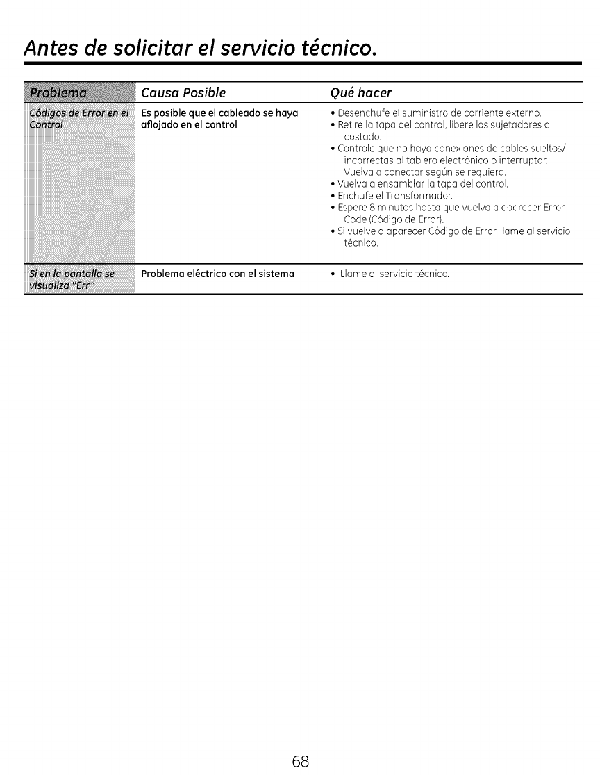
Antes de solicitar el servicio t cnico.
Causa Posible
Es posible que el cableodo se haya
aflojado en el control
Qu_ hacer
• Desenchufe el suministro de corriente externo,
• Retire lu topo del control, libere los sujetadores al
costado.
• Controle que no huya conexiones de cables sueltos/
incorrectus ul toblero electr6nico o interruptor.
Vuelvu a conectar segOn se requiera.
• Vuelva a ensamblar la tapa del control.
• Enchufe el Transformadon
• Espere 8 minutos hasta que vuelva a aparecer Error
Code (C6digo de Error).
• Si vuelve a aparecer C6digo de Error, Ilame at servicio
t_cnico.
Problemo el_ctrico con el sistema • Llame al servicio t_cnico.
uuuuuuuuuuuuuuuuuuuuuuuuuuuuuuuuuuuuuuuuuuuuuuuuuuuuuuu
68
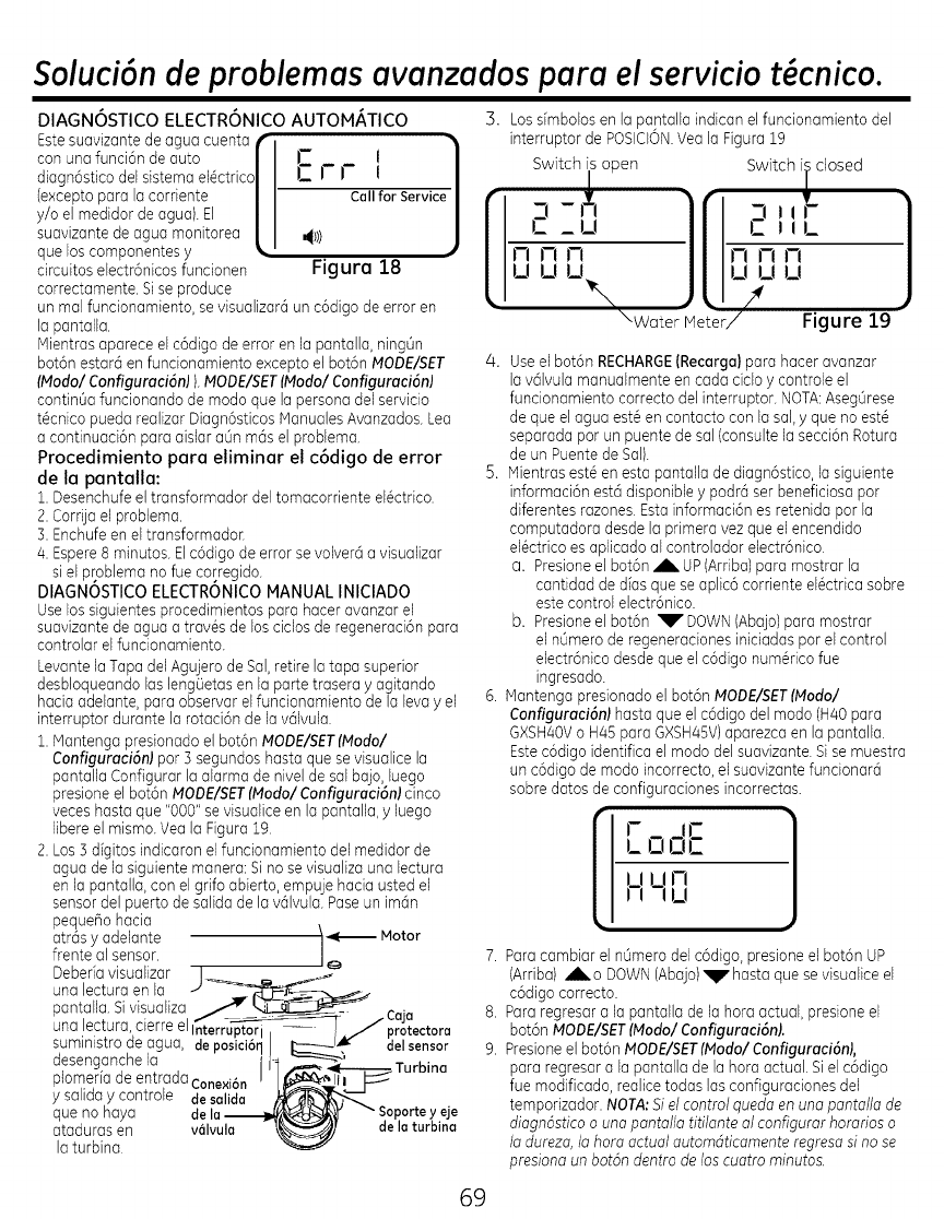
Soluci6n de problemasavanzados para el servicio t cnico.
DIAGNOSTICO ELECTRONICO AUTOM/_TICO
Estesuavizante de agua cuenta f
con una funciGnde auto |
diagnGsticodel sistemael_ctrico/
(exceptopara la corriente |
y/o el medidor de agua). El |
suavizantede agua monitorea |
que loscomponentes y_, "
circuitos electr6nicos funcionen
correctamente. Sise produce
Err l 1
Call for Service /
J
Figura 18
un mal funcionamiento, sevisualizar6 un c6digo de error en
la pantalla.
Mientras aparece el c6digo de error en la pantalla, ning0n
bot6n estar@en funcionamiento excepto el bot6n MODE/SET
IModo/ Configuraci6n) ) MODEISET(Modol Configuraci6nl
contin0a funcionando de modo que la persona del servicio
t@cnicopueda realizar Diagn6sticos ManualesAvanzados.Lea
a continuaciGn para aislar a0n rags el problema.
Procedimiento para eliminar el c6digo de error
de la pantalla:
1. Desenchufeel transformador del tomacorriente el@ctrico.
2. CorrUael problema.
3. Enchufeen eltransformador.
4. Espere8 minutos. ElcGdigode error se volver6 a visualizar
siel problema no fue corregido.
DIAGNOSTICO ELECTRONICO MANUAL INICIADO
Uselos siguientes procedimientos para hacer avanzar el
suavizantede agua a trav@sde los cidos de regeneraci6n para
controlar el funcionamiento.
Levante la Tapadel Agujerode Sal,retire la tapa superior
desbloqueando las leng0etas en la parte trasera yagitando
hacia adelante, para observar el funcionamiento de la leva yel
interruptor durante la rotaciGnde la v01vula.
1. Mantenga presionado el bot6n MODEISET(Modol
Configuraci6n) par 3 segundos hasta que se visualJcela
pantalla Configurar la alarma de nivel de sal bajo,luego
presione el bot6n MODE/SETIModol Configuraci6nl cinco
veceshasta que "000" se visualice en la pantalla,yluego
libereel mismo. Yea la Figura 19.
2. LosS digitos indicaron el funcionamiento del medidor de
agua de la siguiente manera:Si no se visualiza una lectura
en la pantalla, con el grifo abierto, empuje hacia usted el
sensordel puerto de salida de la v01vula.Paseun im0n
pequeflo hacia \
atr0s yadelante /_--- Motor
frente al sensor. /,o 7.
Debefiavisualizar I _._
una lectura en la J-_'_:_ _._.
pantalla Sivisualiza 7_ ^ •
"._ __-- _ - L.aja
una ,lec!ura,?erre elinterr_j protectora 8.
sumlnEs[roae agua, deposici6qI I:---"_J'_ delsensor
desenganchela -4 .__Turbina 9.
plomeriadeentrada_- .. I /_,,r, _"
ysalidaycontrole
que no haya de la_Y _" soportey eje
ataduras en vGIvula -\_] dela turbina
la turbina.
5. Losdmbolos en la pantalla indican el funcionamiento del
interruptor de POSICION.Yea la Figura 19
Switch is open
[
2 ,_,
J-J FI I-I
U U U_x •
\Water Meter/
Switch iLclosed
,_--'llr
i-I rl i-i
ul_lu
!Figure 19
4. Useel botGn RECHARGE(Recarga)para hacer avanzar
la v01vulamanualmente en cada cido ycontrole el
funcionamiento correcto del interruptor. NOTA:Aseg0rese
de que el agua est@en contacto con la sal, yque no est@
separada par un puente de sal (consulte la secciGnRotura
de un Puentede Sal).
5. Mientras est@en esta pantalia de diagnOstico,la siguiente
informaciOnest0 disponibleypodr0 ser beneficiosa par
diferentes razones. Estainformaci6n es retenida par la
computadora desde la primera vez que el encendido
el@ctricoes aplicado al controlador electrOnico.
a. Presioneel bot6n ,A.UP (Arriba)para mostrar la
cantidad de dias que seaplic6 corriente el@ctricasabre
estecontrol electrGnico.
b. Presioneel botOn V DOWN(Abajo)para mostrar
el n0mero de regeneracionesiniciadas par el control
electr6nico desde que el cGdigonum@ricofue
ingresado.
6. Mantenga presionado el bot6n MODE/SETIModol
Configuraci6n) hasta que el cGdigodel modo (H40para
GXSH40Vo H45 para GXSH45V)aparezca en la pantalla.
EstecGdigoidentifica el modo del suavizante.Sise muestra
un cGdigode modo incorreeto,el suavizantefuncionarO
sabre datosde configuraciones incorrectas.
ilrl
Hnu
Paracambiar el nLimerodel cGdigo,presione el botGn UP
(Arriba) Al_.o DOWN(Abajo)vhasta que sevisualice el
cGdigocorrecto.
Para regresara la pantalla de la hora actual, presione el
baton MODEISETIModol Configuraci6nl.
Presioneel bot6n MODE/SET(Modal ConfigurociGnL
para regresar a la pantalla de la hora actual. Siel c6digo
fue modificado, realice todas lasconfiguraciones del
temporizador. NOTA;Siel control quedoen uno pontollo de
diagnGsticoouna pantalla titilonte al configurar hororioso
la dureza,la hora actual outomdticomenteregreso si no se
presiono un botdn dentro de los cuotro minutos.
69
SoluciGndeproblemasavanzadospara elserviciot cnico.
Servicio: Control de Recarga Avanzado en forma Manual
NOTA: La pantallode controldebe mostrarelhoratiode
monero fUo(notitilondo).
1. Presione el bot6n RECHARGE (Recerge) y mont#ngolo
presionodo pot tres segundos. RECHARGEIRecerge)
comienzo o titilor o medido que el sistemo suovizonte
ingreso ol cido de Ilenodo de Io recorgo. Retire Io topo
del pozo de solmuero y, usondo una linterno, observe
el oguo ol ingresor ol tonque de solmuero. Si el oguo
no ingreso ol tonque, busque uno obstrucci6n en Io
boquillo, el venturi, el enchufe de flujo de Ilenodo o Io
tubeFo de Io solmuero. Consulte Io secci6n Cuidodo y
Limpiezo del Sistemo Suovizonte de Aguo.
2. Luego de observar el Ilenado, presione el bot6n
RECHARGEIRecerge) poro que el sistemo suovizonte
de oguo pose ol ogregodo de solmuero. Comenzor6
un flujo lento de oguo basra el drenoje. Verifique el
ingreso de solmuero desde el tonque de solmuero
iluminondo con uno lintemo el pozo de solmuero y
observondo un descenso notorio del nivel de Ifquido
duronte un peFodo de tiempo prolongodo (hosto 20
minutos).
NOTA: AsegOrese de que un puente de sol no est@
impidiendo que el oguo tengo contocto con Io sol.
Consulte Io secd6n Cuidodo y Limpiezo del Sistemo
Suovizonte de Aguo.
Si el sistema suovizonte de ogua no haee que ingrese
solmuero, eontrole:
, Sudedod o defectos en Io boquillo y/o el ventufi.
, Defecto en el sellodo de Io boquillo y el venturi.
, Lo boquillo y el venturi no estan correctamente
sellodos en Iojunto.
, Otro defecto de Io vGIvulo interno (sellodo del rotor,
rotor y disco, arandelo onduloda, etc.).
, Drenoje restringido (controle el occesorio y Io
monguero de drenoje).
NOTA:Siel sistemo de presiGndel agua esbajo, una
manguerade drenajeelevadopodr6 ocasionar presiGn
trasera,deteniendoel ingresodesalmuera.
3, Nuevomente, presione el bot6n RECHARGE{Recerge)
poro posor del sistemo suovizonte de oguo ol Iovodo
regresivo. Busque un flu]o rGpido de oguo desde Io
monguero de drenoje. Un flu]o lento indico que hay
un distribuidor superior, una tapa de flujo de Iovado
regresivo o uno monguero de drenoje otoscados.
4. Presione el bot6n RECHARGE(Recorgo) poro posor
el sistemo suovizonte de oguo ol enjuogue rGpido.
Nuevomente bosque un flujo de drenoje rGpido. Deje
que el sistemo suovizonte de oguo se enjuogue por
unos minutos poro descorgor cuolquier resto de
solmuero en el tanque de resino de Io evoluoci6n del
cido de ogregodo de solmuero.
S. Para hacer que el sistema suavizante de agua vuelvo
a funcionar, presione el bot6n RECHARGE {Recorgo).
70

Vista E×pandida.
ii
4
55
29
36m
m19
(_o
24m
23
{
}
25
71
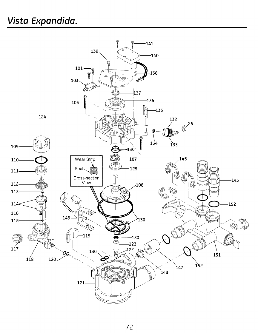
Vista E×pandida.
139
124
109--
I
1i0---------0
113
118
Cross-section
View
132
134 133
147
148
152
--152
72
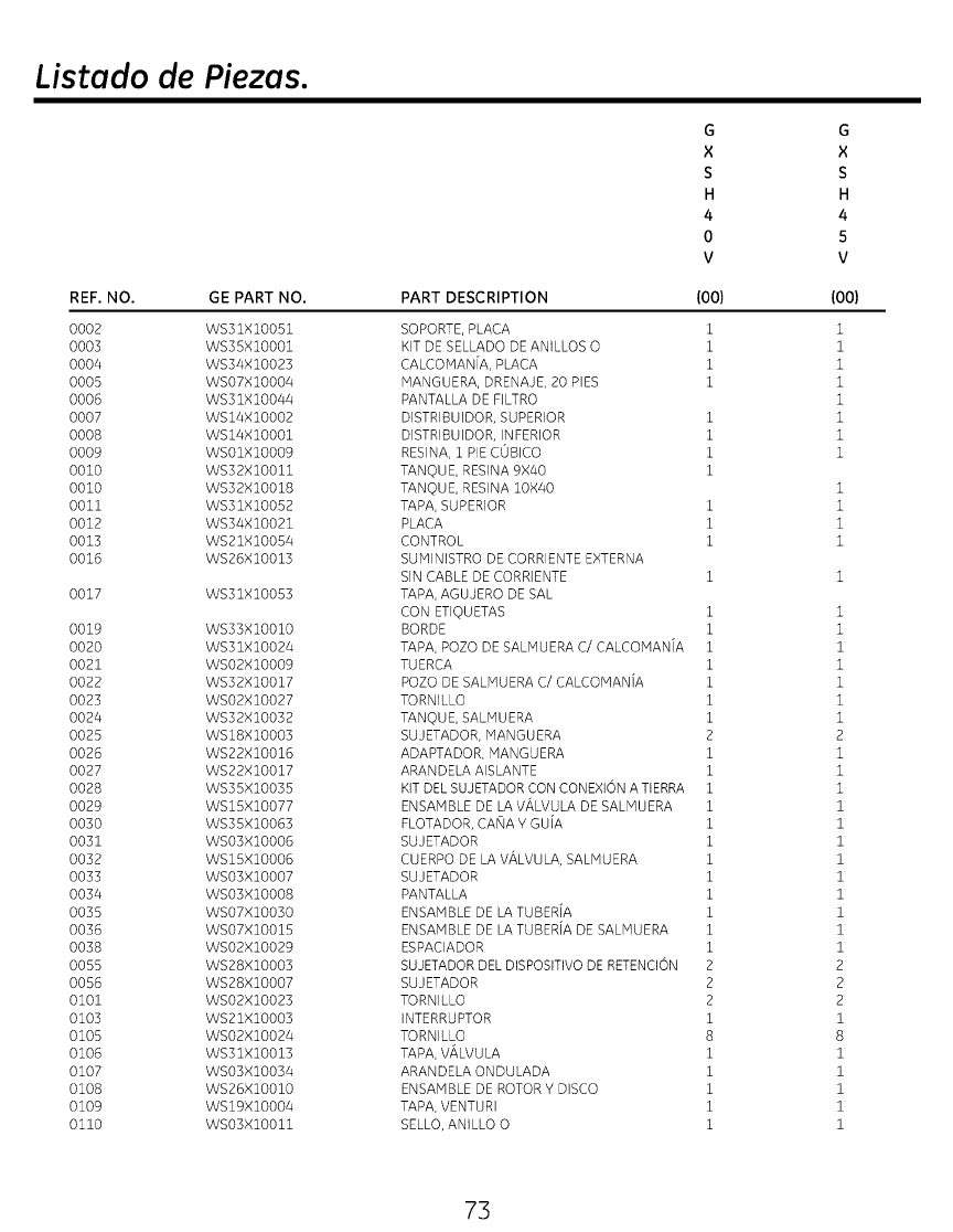
Listado de Piezas.
REF. NO. GE PART NO.
0002 WS31XIO051
0003 WS35XIO001
0004 WS34XIO023
0005 WSO7XIO004
0006 WS31XIO044
0007 WSI4XIO002
0008 WSI4XIO001
0009 WSO1XIO009
0010 WS32XlO011
0010 WS32XlO018
0011 WS31XlO052
0012 WS34XlO021
0013 WS21XlO054
0016 WS26XlO013
0017 WS31XlO053
0019 WS33XlO010
0020 WS31XlO024
0021 WSO2XIO009
0022 WS32XlO017
0023 WSO2XlO027
0024 WS32XlO032
0025 WS18XlO003
0026 WS22XlO016
0027 WS22XlO017
0028 WS35XIO035
0029 WSI5XlO077
0030 WS35X10063
0031 WS03X10006
0032 WS15XIO006
0033 WSO3XIO007
0034 WSO3XIO008
0035 WSO7XIO030
0036 WSO7XlO015
0038 WSO2XlO029
0055 WS28XlO003
0056 WS28XlO007
0101 WSO2XlO023
0103 WS21XIO003
0105 WSO2XlO024
0106 WS31XlO013
0107 WSO3XlO034
0108 WS26XlO010
0109 WS19XlO004
0110 WSO3XIO011
G
X
S
H
4
0
V
G
×
S
H
4
5
V
PART DESCRIPTION {O0) {O0)
SOPORTE, PLACA 1
KIT DE SELLADO DE ANILLOS O 1
CALCOMAN[A, PLACA 1
MANGUERA, DRENAJE, 20 PIES 1
PANTALLA DE FILTRO
DISTRIBUIDOR, SUPERIOR 1
DISTRIBUIDOR, INFERIOR 1
RESINA, 1 PIE COBICO 1
TANOUE, RESINA 9X40 1
TANOUE, RESINA 10X40
TAPA, SUPERIOR 1
PLACA 1
CONTROL 1
SUMINISTRO DE CORRIENTE EXTERNA
SIN CABLE DE CORRIENTE 1
TAPA, AGUJERO DE SAL
CON ETIQUETAS 1
BORDE 1
TAPA, POZO DE SALMUERA C/CALCOMAN[A 1
TUERCA 1
POZO DE SALHUERA C/CALCOMAN[A 1
TORNILLO 1
TANOUE, SALMUERA 1
SUJETADOR, MANGUERA 2
ADAPTADOR, MANGUERA i
ARANDELA AISLANTE i
KIT DEL SUJETADOR CON CONEXION A TIERRA i
ENSAMBLE DE LA V#LVULA DE SALMUERA i
FLOTADOR, CA_IA Y GUiA i
SUJETADOR i
CUERPO DE LA VALVULA, SALMUERA i
SUJETADOR i
PANTALLA i
ENSAMBLE DE LA TUBERiA i
ENSAMBLE DE LA TUBERiA DE SALMUERA i
ESPACIADOR i
SUJETADOR DEL DISPOSITIVO DE RETENCION 2
SUJETADOR 2
TORNILLO 2
INTERRUPTOR i
TORNILLO 8
TAPA, V#LVULA i
ARANDELA ONDULADA i
ENSAMBLE DE ROTOR Y DISCO i
TAPA, VENTURI i
SELLO, ANILLO O i
73
1
1
1
1
1
1
1
1
i
i
i
i
1
1
1
1
1
1
1
2
1
1
1
1
1
1
1
1
1
1
1
1
2
2
2
1
8
1
1
1
1
1
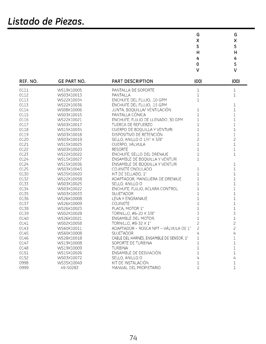
Listado de Piezas.
REF. NO. GE PART NO.
0111 WSI9XIO005
0112 WSOJXIO013
0113 WS22XIO034
0113 WS22XIO036
0114 WSO8XIO006
0115 WSOJXIO015
0116 WS22XIO021
0117 WSOJXIO017
0118 WSI5XIOO34
0119 WSOJXIO018
0120 WSOJXIO019
0121 WSI5XIO025
0122 WSOJXIO020
0123 WS22XIO022
0124 WSI5XIO027
0124 WSI5XIO036
0125 WS03X10043
0130 WS35XIO020
0132 WS22XIO058
0133 WSOJXIO025
0134 WSO3XIO022
0135 WSO3XIO033
0136 WS26XIO008
0137 WS26XIO009
0138 WS26XIO023
0139 WSOBXIO028
0140 WS26XIO021
0141 WSOBXIO058
0143 WS6OXIO011
0145 WS6OXIO008
0146 WS28XIO018
0147 WSI9XIO008
0148 WSI9XIO009
0151 WSI5XIO026
0152 WSO3XIO072
0998 WS35XIO049
0999 49-50283
G
X
S
H
4
0
V
PART DESCRIPTION (00)
PANTALLA DE SOPORTE 1
PANTALLA 1
ENCHUFE DEL FLUJO, .10 GPM 1
ENCHUFE DEL FLUJO, .15 GPM
JUNTA, BOOUILLA/VENTILACION i
PANTALLA CONICA i
ENCHUFE, FLUJO DE LLENADO .30 GPM i
TUERCA DE REFUERZO i
CUERPO DE BOq)UILLA Y VENTUR] 1
DISPOSITIVO DE RETENCION i
SELLO, ANILLO O 1/4" X 3/8" 2
CUERPO, VALVULA i
RESORTE i
ENCHUFE, SELLO DEL DRENAJE i
ENSAMBLE DE BOQ)UILLA Y VENTURI i
ENSAMBLE DE BOOUILLA Y VENTURI
COJINETE ONDULADO i
KIT DE SELLADO, 1" i
ADAPTADOR, MANGUERA DE DRENAJE i
SELLO, ANILLO 0 i
ENCHUFE, FLUJO, ACLARA CONTROL i
SUJETADOR i
LEVA Y ENGRANAJE i
COJINETE i
PLACA, MOTOR 1" 1
TORNILLO, #6-20 X 3/8" 3
ENSAMBLE DEL MOTOR. i
TORNILLO, #8-32 X 1" 2
ADAPTADOR - ROSCA NPT - VALVULA DE 1" 2
SUJETADOR 4
CABLE DEL HARNES, ENSAMBLE DE SENSOR, i" i
SOPORTE DE TURBINA i
TURBINA i
ENSAMBLE DE DESVIACION i
SELLO, AN]LLO O 4
KIT DE INSTALACION i
MANUAL DEL PROPIETARIO i
G
X
S
H
4
5
V
(00)
i
i
1
1
i
1
i
1
i
2
1
i
1
1
1
1
1
1
i
1
1
1
1
3
1
2
2
4
i
1
i
1
4
1
1
74
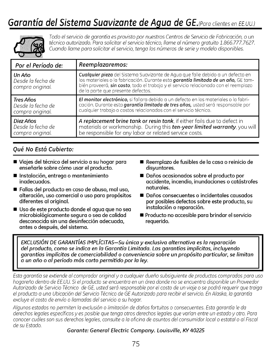
GaranUa del Sistema Suavizante de A lua de GE. po o
Todo elservicio de garanda esprovisto par nuestros Centrosde Serviciode Fobricaci6n,o un
tdcnico autorizado. Para solicitor el serviciotdcnico, llama al nOmero gratuito 1.866.777.7627.
Cuando llama para solicitor el servicio,tango losnOmeros de seriey modelo disponibles.
Par el Periodo de: Reemplazaremos:
UnASo Cualquierpiezadel SistemaSuavizantede Agua quefalle debidoa un defecto en
Desde/o fecho de losmatedaleso lafabricad6n. Duranteestagarantfa limitada de un afro,GEtam-
compro original, bi_nproveer&sin costa, todo eltrebejo y el serviciorelecionedocon elreemplezo
de Io perte qua presentedefectos.
Ires Arias Elmonitor electr6nico,sifoliate debidoa undefecto enlosmaterialeso lafabri-
Desde/a fecha de caci6n.DuranteestagaranUa limitadade tres afros,ustedset@responsablepar
compro original, cualquiertrabajo o costosrelacionadoscon elserviciot6cnico.
DiezAfios A replacement brine tank or resin tank, if either foils due to defect in
Desde lo fecho de materials or workmanship. During this ten-year limited warranty, you will
compro original, be responsible for any labor or related service costs.
Qu_ No Est6 Cubierto:
• Viajes del t_cnico del servicio a su hogar para
ensefiarle sabre cGmo usar el producto.
• InstalaciGn, entrega o mantenimiento
inadecuados.
• Fallas del producto en caso de abuso, mal usa0
alteraciGn, usa comercial o usa para propGsitos
diferentes al original.
• Usa de este producto donde el agua que no sea
microbiolGgicamente segura o sea de calidad
desconocida sin una desinfecciGn adecuada,
antes o despu_s, del sistema.
• Reemplazo de fusibles de la casa o reinicio de
disyuntores.
• Da_os ocasionados sabre el producto par
accidente0 incendio, inundaciones o catGstrofes
naturales.
• Dafios consecuentes o incidentales causados
par posibles defectos sabre este producto, su
instalaciGn o reparaciGn.
• Producto no accesible para brindar el servicio
requerido.
EXCLUSION DE GARANT[AS IMPL[CITAS--Su Bnica y exclusiva alternativa es la reparaci6n
del producto, como se indica en la Garantia Limitada. Las garanUas implicitas, incluyendo
garantias implicitas de comerciabilidad o conveniencia sobre un prop6sito particular, se limitan
a un afio oal periodo m6s corto permitido por la ley.
Estagaranda se extiendeal comprador originaly a cualquier due_osubsiguientedeproductos compradospara usa
hogare_o dentro de EE.UU.Siel producto se encuentra en un dreadonde no se encuentradisponibleun Proveedor
Autorizado de Servicio Tdcnicode GE,usted serdresponsablepar el costa de un viaje o sepodr4 requerir qua traiga
elproducto auna Ubicacidndel ServicioTdcnicode GEAutorizado paro recibir el servicio.EnAlaska,Io garantfa
excluyeel costa de envfo o Ilamadasdel servicioa su hogan
Algunosestadosno permiten la exclusidno limitacidn de dahos fortuitos o consecuentes.Estagaranda le do
derechoslegalesespedficosyesposible quatango otros derechoslegalesqua varfanentre un estadoy otto. Para
conocercudlesson sus derechoslegales,consulteala oficina de asuntos del consumidorlocal o estatal o al Fiscal
desu Estado. Garante: General Electric Company. Louisville, KV40225
7S
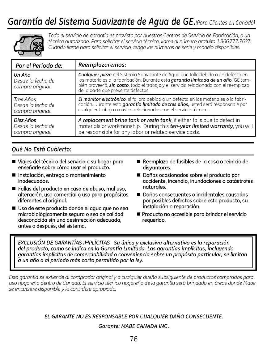
Garantia del Sistema Suavizante de Agua de EJparaClientesen Canadd)
Todo elservicio de garantfa esprovisto par nuestros Centrosde Serviciode Fobricaci6n,o un
tdcnico autorizado. Para solicitor el serviciotdcnico, llame al nOmero gratuito Z866. 777.7627.
Cuando llame para solicitor el servicio,tenga losnOmeros de seriey modelo disponibles.
Por el Periodo de: Reemplazaremos:
Un ASo Cualquierpieza del SistemaSuavizantede Agua quefalle debido a un defecto en
Desde lo fecho de losmaterialeso la fabricaci6n.Duranteestagorontio limitada deunafro,GEtam-
compro original, bi@nproveer&sin costa, todo el trabajo yelservicio relacionadocon elreemplazo
de ]aparte quepresentedefectos.
Ires Arias Elmonitor electr6nico,si fallara debidoa un defectoen losmaterialeso lafabri-
Desde/a fecha de caci6n. Duranteestagorontfa limitododetres arias,ustedsera responsablepar
compro original, cualquier trabajo o costosrelacionadoscon elserviciot6cnico.
DiezAfios A replacement brine tank or resin tank, if either fails due to defect in
Desde lo fecha de materials or workmanship. During this ten-year limited warranty, you will
compro original, be responsible for any labor or related service costs.
Qu_ No Est6 Cubierto:
•Viajes del t6cnico del servicio a su hogar para
ensefiarle sobre c6mo usar el producto.
•Instalaci6n, entrega o mantenimiento
inadecuados.
•Fallas del producto en caso de abuso, mal uso0
alteraci6n0 uso comercial o uso para prop6sitos
diferentes al original.
• Uso de este producto donde el agua que no sea
microbiol6gicamente segura o sea de calidad
desconocida sin una desinfecci6n adecuada,
antes o despu_s, del sistema.
• Reemplazo de fusibles de la casa o reinicio de
disyuntores.
• Dafios ocasionados sobre el producto por
accidente0 incendio, inundaciones o cat6strofes
naturales.
• Dafios consecuentes o incidentales causados
por posibles defectos sobre este producto, su
instalaci6n o reparaci6n.
• Producto no accesible para brindar el servicio
requerido.
EXCLUSION DE GARANTIAS IMPLICITAS--Su 6nica y exclusiva alternativa es la reparaci6n
del producto, como se indica en la Garan6a Limitada. Las garan6as implicitas, incluyendo
garan6as implicitas de comerciabilidad o conveniencia sobre un prop6sito particular, se limitan
a un afio oal periodo m6s corto permitido por la ley.
Estagaranda se extiende al comprador original y a cualquier dueho subsiguiente deproductos comprodos para
usa hogarefio dentro de Canadd. Elservicio tdcnico hogareho de la garanda serd brindado en dreasdonde Mabe
se encuentre disponibley 1oconsidere opropiado.
EL GARANTE NO ES RESPONSABLE POR CUALQUIER DAI¢IO CONSECUENTE.
Garante: MABE CANADA INC.
76
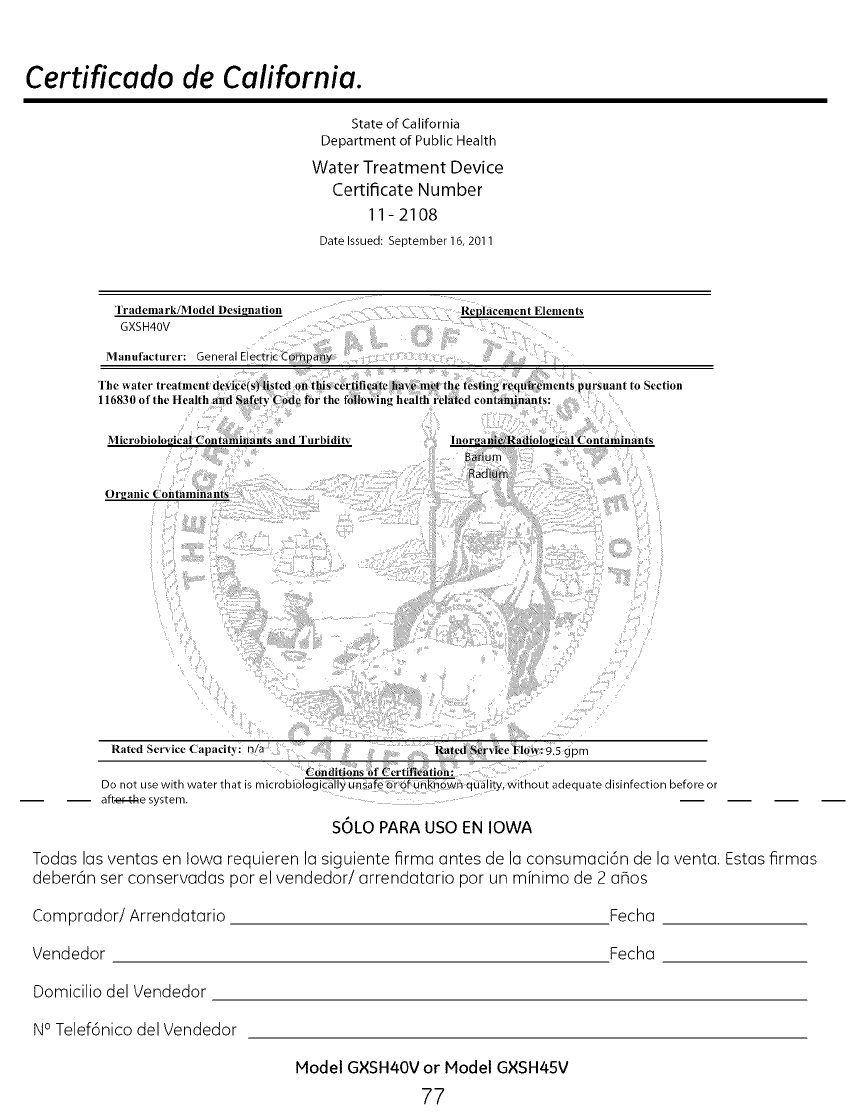
Certificado de California.
State of California
Department of Public Health
Water Treatment Device
Certificate Number
11-2108
Date Issued: September 16, 2011
Irademark/Model Desif_nalion
GXSH40V
Manufacturer: General Electric-Company
The _+aler lrearlnell
116830 of the Health and Safety
Microbiological Contaminants and "lurbidit_
Repldcement Elements
cction
Organic Contaminants
Rated Service ('apacity: n/a Rated _;ervlrc Flow: 9.5 gpm
Conditions of ('ertffieatlon:
Do not use with water that is microbiologieallyunsafeorof unknown quality, without adequate disinfection before or
aft._r-t-he system.
SOLO PARA USO EN IOWA
Todas las ventas en Iowa requieren la siguiente firma antes de la consumaci6n de la venta. Estas firmas
deberan ser conservadas por el vendedor/arrendatario por un mfnimo de 2 aBos
Comprador/Arrendatario Fecha
Vendedor Fecha
Domicilio del Vendedor
N° Telef6nico del Vendedor
Model GXSH40V or Model GXSH45V
77
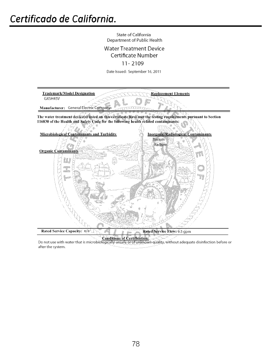
Certificado de California.
State of California
Department of Public Health
Water Treatment Device
Certificate Number
11 - 2109
Date Issued: September 16, 2011
l"rademark/Model Designation
GXSH45V
Manufacturer: 3eneral ElectricCompany
Rep|acelnent Elements
Microbiological Contaminan:_s and Turbidity
Organic Contanfinants
Rated Serv ce Capac ty n/a Ratcd:Serviee Flow: 9.5 gpm
Conditi0ns of Cerlifieation:
Do not use with water _na_ is microbiologically unsafe or of unknown ooa ty, without adequate disinfection before or
after the system.
78
Soporte al Consumidor.
Pdgina Web de GE Appliances GEAppliances.com
?Tienealguna pregunta sabre su electrodom6stico? iPruebe la pagina Web de GEAppliances 2/4horas
al dfa, cualquier dia del aBo! Para mayor convenienda y servido mds rapido, ya puede descargar los
Manuales de los Propietados o pedir piezas en linea.
Solicite una reparaci6n GEAppliances.com
Elservicio de expertos GEest6 atan s61oun paso de su puerta. Llame al 800.GE.CARES(800./432.2737)
durante horas normales de ofidna para solidtar su reparad6n.
RealLife Design Studio
(Estudiode diseho para la vida real) GEAppliances.com
GEapoya el concepto de Diseho Universal--productos, servicios yambientes que pueden usar genre de
todas lasedades, tama_os ycapacidades. Reconocemos ]a necesidad de disehar para una gran gama
de habilidades ydificultades £sicas ymentales. Para m6s detalles cobre 1asaplicaciones de GEDise_o
Universal, induyendo ideasde dise_o para la cocina para personas con discapacidades, mire nuestra
pagina Web hay mismo. Para personas con dificultades auditivas, favor de Ilamar al 800.TDD.GEAC
(800.833./4322).
Garantias amptiadas GEAppliances.com
Compre una garantTaampliada yobtenga detalles sabre descuentos especiales disponibles mientras su
garantia est@a0n activa. Puedecomprada en linea en cualquier momenta, o Ilamar al (800.626.222/41
durante horas normales de ofidna. GEConsumer Home Services estar6 a0n ahi cuando su garantia
termine.
Piezas y accesorios GEAppliances.com
Aquellos individuos con la calificaci6n necesaria para reparar sus propios electrodom6sticos pueden
pedir que se les manden las piezas o accesodos directamente a sus hogares (aceptamos las tarjetas
VISA,MasterCard yDiscover). Haga su pedido en linea hay, 2/4horas cada dia o Ilamar par tel6fono al
800.626.2002 durante horas normales de oficina.
Las instrucciones descritas en este manual cubren los procedimientos a seguir par cualquier usuario.
Cualquier otra reparad6n debeda, par regla general, referirse a personal calificado autorizado. Debe
ejercerse precaud6n ya que 1asreparadones incorrectas pueden causar condidones de fundonamiento
inseguras.
P6ngase en contacto con nosotros GEAppliances.com
Sino esta satisfecho con el servicio que recibe de GE,p6ngase en contacto con nosotros en nuestra
pagina Web indicando todos los detalles asf coma su n0mero de tel6fono o escrfbanos a:
General Manager, Customer Relations
GEAppliances,Appliance Park
Louisville, KY/40225
Registre su etectrodom_stico GEAppliances.com
iRegistre su nuevo electrodom6stico en Ifnea-cuando usted prefiera! Elregistrar su producto a tiempo
le proporcionar6, si surgiera la necesidad, una mejor comunicaci6n yun servicio m@sr6pido bajo los
t6rminos de su garantia. Tambi6n puede enviar su tarjeta de registro pre-impresa que se induye en el
material de embalaje.
79
ConsumerSupport.
GE Appliances Website GEAppliances.com
Have a question or need assistance with your appliance? Try the GEAppliances Website 2/4hours a day,
any day of the year! For greater convenience and faster service,you can now download Owner's
klanuals or order parts online.
Schedule Service GEAppliances.com
Expert GErepair service isonly one step away from your door. Schedule your service at your
convenience by calling 800.GE.CARES(800./432.2737)during normal business hours.
Real LifeDesign Studio GEAppliances.com
GEsupports the Universal Design concept-products, services and environments that can be used by
people of all ages, sizesand capabilities. We recognize the need to design for a wide range of physical and
mental abilities and impairments. For details of GE's Universal Design applications, including kitchen design
ideas for people with disabilities, check out our Website today. For the hearing impaired, please call 800.
TDD.GEAC(800.833./4322).
Extended Warranties GEAppliances.com
Purchase a GEextended warranty and learn about special discounts that are available while your
warranty is still in effect. You can purchase it on-line anytime, or call 800.626.222/4during normal business
hours. GEConsumer Home Serviceswill still be there after your warranty expires.
Parts and Accessories GEAppliances.com
Individuals qualified to service their own appliances can have parts or accessories sent directly to their
homes (VISA,klasterCard and Discover cards are accepted). Order on-line today, 2/4hours every day or
by phone at 800.626.2002 during normal business hours.
Instructions contained in this manual cover procedures to be performed by any user.Other servicing
generally should be referred to qualified service personnel. Caution must be exercised,since improper
servicing may cause unsafe operation.
Contact Us GEAppliances.com
If you are not satisfied with the service you receive from GE,contact us on our Website with all the details
including your phone number, or write to: General Manager, Customer Relations
GEAppliances, Appliance Park
Louisville,KY40225
Register Your Appliance GEAppliances.com
Registeryour new appliance on-line--at your convenience! Timely product registration will allow for
enhanced communication and prompt service under the terms of your warranty, should the need arise.
You may also mail in the pre-printed registration card included in the packing material, or detach and
use the form in this Owner's Manual.
80
