GE JV695SWW User Manual RANGE HOOD Manuals And Guides L0406350
GE Range Hood Manual L0406350 GE Range Hood Owner's Manual, GE Range Hood installation guides
User Manual: GE JV695SWW JV695SWW GE RANGE HOOD - Manuals and Guides View the owners manual for your GE RANGE HOOD #JV695SWW. Home:Kitchen Appliance Parts:GE Parts:GE RANGE HOOD Manual
Open the PDF directly: View PDF ![]() .
.
Page Count: 8
36" Vented Hood
_Safety Instructions...Front Cover, 2
_Operating Instructions .........2,3
Automatic Heat Sensor ...........................3
Controls .....................................................2
Cleaning ....................................................3
Filter............................................................3
Light Bulb Replacement ..........................3
Installation .....................................4-6
Damper/Duct Connector .........................5
Electrical Wiring .......................................6
Filter Panel .............................................3, 5
Mounting Brackets ...................................5
Consumer Services .....................7
Important Phone Numbers .....................7
Warranty ..................................Back Cover
IMPORTANTSAFETYINFORMATION.
READALLINSTRUCTIONSBEFOREUSING.
SAFETYPRECAUTIONS
WARNING- To REDUCETHERISKOFFIRE,
ELECTRICSHOCKORINJURY TOPERSONS,
OBSERVETHEFOLLOWING:
A. Use this unit only in tile manner intended
by the manufacturer, lfyou have questions.
contact the manufactm'e_
B. Before smwidng or cleaning umt. switch
WARNING- To REDUCETHERISKOFA
RANGETOPGREASEFIRE:
A. Never lem e surface units unattended at high
settings. Boilovers cause smoking and gTeasy
spillovers that may ignite. Heat oils slowly on
low or medium settings.
B. Ahva) s turn hood ON when cooking at high
power off at service panel and lock the service heat or when cooking flaming foods.
disconnecting means to prevent power fl'om
being switched on accidentally. When the
selwice disconnecting means cannot be locked.
securely fasten a prominent wm'ning device,
such as a tag, to the smMce panel.
C. Do not use this unit with an) solid-state speed
control device.
C. Clean ventilating fans fl'equenfly. Grease should
not be allowed to accmnulate on fian or filter.
D. Use proper pan size. Mways use cookware
appropriate for the size of the surface
element.
co_ztimted _zextpage
D. [ se with approved cord-connection kit only.
E. This unit must be grounded.
GEAppfiances
IModels: JV694 JV695 JV696 JV960
IMPORTANTSAFETYINFORMATION.
READALLINSTRUCTIONSBEFOREUSING.
SAFETYPRECAUTIONS
CAUTION-For_e,eralve,tilati,guseo,Iv.oo,or
use to exhaust hazardous or explosive materials and vapors.
WARNING-To REDUCETHERISKOFINJURY TO
PERSONSIN THEEVENTOFA RANGETOPGREASEFIRE,
OBSERVETHEFOLLOWING*:
A. SIVIOTHER FIAIVIES with a close-fitting lid,
cookie sheet, or metal tray, then turn off the burner.
BE CAREFUL TO PREVENT BURNS. If the flames
do not go out immediately, E\%CUATE AND CALL
THE FIRE DEPARTMENT.
B. NEX.%R PICK UP A FLAMING PAN _bu ma)
be burned.
C. DO NOT USE WATER. including wet dishcloths
or towels--a violent steam explosion will result.
D. Use an exunguisher ONLY if:
1. You know you have a Class ABC extinguisher
and you already know how to operate n.
2. The fire is small and contained in the area
where it started.
WARNING- TOREDUCETHERISKOFFIRE,
ELECTRICSHOCKORINJURY TOPERSONS,OBSERVETHE
FOLLOWING:
A. Installation work and electrical wiring must be done bx
qualified persom s) in accordance with all applicable
codes and standards, including fire-rated construction.
B. Sufficient air is needed {bl"proper combustion and
exhausting of gases through the flue (chimney) ot
fuel burning equipment to prevent back drafting.
Follow the heating equipment manufacturer's
guideline and safety standards such as those
published by the National Ffi'e Protection Assocmtion
(NFPAL and the American Societ_ for Heating,
Refligeration and Air Conditioning Engineers
(ASHRAEL and the local code authorities.
C. When cutting or drilling into wall or ceiling, do not
damage electrical wiring and other hidden utilities.
D. Ducted fans must always be vented to the outdoors.
WARNING- TOREDUCETHERISKOFFIRE,
3. The fire department is being ca
4. You can fight the fire with your back to an exit.
* Based on "Kitchen Firesafety Tips" published b} NFPA.
• Do not attempt to repair or replace an} part of) our
hood unless it is specificall} recommended in this
guide. All other servicing should be referred to a
qualified technician.
READANDFOLLOWTHISSAFETYINFORMATIONCAREFULLY.
READAND SAVETHESEINSTRUCTIONS
OPERATING INSTRUCTIONS
Always turn your hood on before you begin cooking to establish an air flow
in the kitchen. Let the hood run for a few minutes to clean the air after you
turn the range off. This will keep the whole kitchen cleaner.
Controls
The hood is "OFF" when the glass visor is pushed
completely in.
LIGHT-The light will turn "ON" when the glass
visor is pulled out approximately 1/2 inch.
BLOWER-The blower will turn "ON" when the
drawer is pulled out approximately 1½ inches.
The blower speed is set using the slide control,
located to the right of the drawer.
2
Automatic Heat Sensor
Your hood is equipped with an automatic thermostat.
This thermostat is a device that will turn on or speed
up the blower if it senses excessive heat above the
cooking surface.
If your blower is not on, or if it is running at low speed,
the thermostat will sense excessive cooking heat,
override the norn-lal blower control and turn the blower
on to high speed. _l_e blower will run until the
temperature drops to normN operating level. The blower
will then automatically return to its original setting.
CARE AND CLEANING
WARNING: ALWAYS DISCONNECT ELECTRIC POWER SUPPLY BEFORE SERVICING HOOD.
Use a mild detm_ent suitable for painted surfaces.
DO NOT USE ABRASIVE CLOTH, STEEL WOOL
PADS, OR SCOURING POWDERS. Vacuum the
blower to clean it. Do not immerse the blower in water.
The glass visor assembly and light lens are easily
removable for cleaning:
DO NOT clean in a dishwasher.
Remove the light lens by opening the filter panel and
turning the 2 metal clips holding the lens in place.
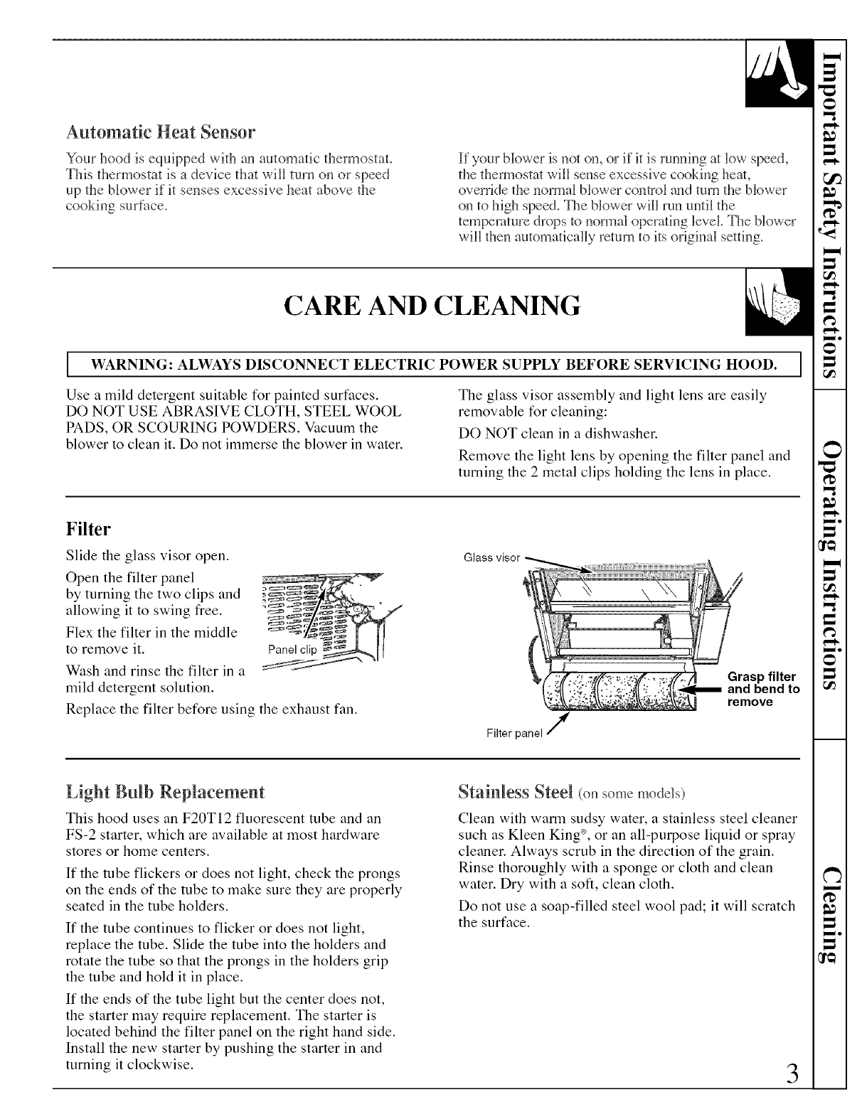
Filter
Slide the glass visor open.
Open the filter panel
by turning the two clips and
allowing it to swing fi'ee.
Flex the filter in the middle
to remove it. Panelclip
Wash and rinse the filter in a
mild detergent solution.
Replace the filter before using the exhaust fan.
Glass visor
Filter panel /
Grasp filter
remove
Light Bulb Replacement
This hood uses an F20TI2 fluorescent tube and an
FS-2 starter, which are available at most hardware
stores or home centers.
If the tube flickers or does not light, check the prongs
on the ends of the tube to make sure they are properly
seated in the tube holders.
If the tube continues to flicker or does not light,
replace the tube. Slide the tube into the holders and
rotate the tube so that the prongs in the holders grip
the tube and hold it in place.
If the ends of the tube light but the center does not,
the starter may require replacement. The starter is
located behind the filter panel on the right hand side.
Install the new starter by pushing the starter in and
turning it clockwise.
Stainless Steel (onsomemodds)
Clean with warm sudsy water, a stainless steel cleaner
such as Kleen King _, or an all-purpose liquid or spray
cleaner. Always scrub in the direction of the grain.
Rinse thoroughly with a sponge or cloth and clean
water. Dry with a soft, clean cloth.
Do not use a soap-filled steel wool pad; it will scratch
the surface.
3
TOOLSYOU WILL NEED
Flat blade and Phillips
screwdrivers
Duct tape
Pencil
Saw (saber or keyhole)
Electric Drill
Pliers
Metal Snips
(in some applications)
Tape measure
Wire stripper
Caulking
Flashlight
Level
PLANTHEINSTALLATION
Caution: Remove the house fuse or open the
circuit breaker before beginning the installation.
Your new hood will fit astandard 36" wide flush bottom
or recessed bottom, framed or frameless kitchen cabinet
which has aminimum depth of 11" from the face to
the inside of the back wall.
The unit is ducted vertically. To change to horizontal
ducting see the instructions.
For safe operation, the mounted hood must be
aminimum of 18" above the cooking surface.
For easiest installation, the range hood should be
installed in the cabinet before mounting the cabinet to
the wall.
NOTE: Remove the glass visor from the
unit before installing the hood in the cabinet
to protect the visor from damage.
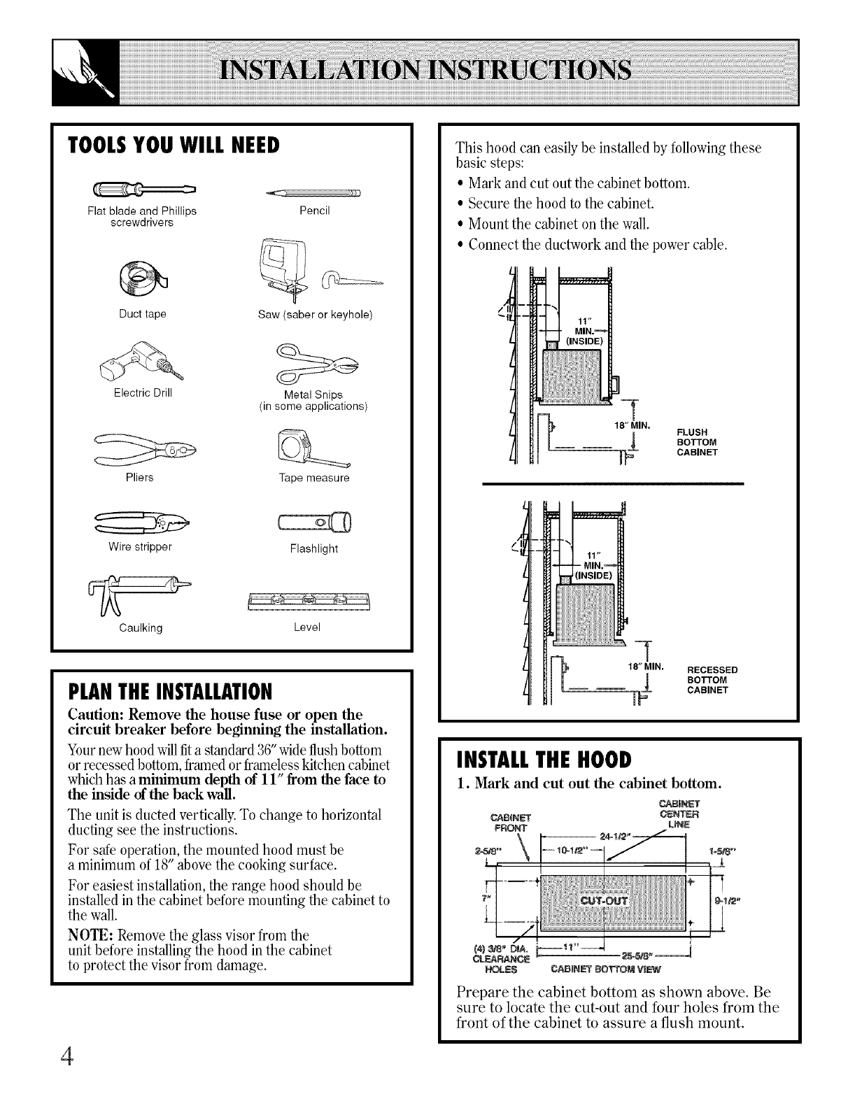
This hood can easily be installed by following these
basic steps:
• Mark and cut out the cabinet bottom.
• Secure the hood to the cabinet.
• Mount the cabinet on the wall.
• Connect the ductwork and the power cable.
/
18" MIN,
¢FLUSH
BOTTOM
CABINET
q-
_= 18" MIN. RECESSED
_=_ BOTTOM
CABINET
INSTALLTHEHOOD
1. Mark and cut out the cabinet bottom.
Prepare the cabinet bottom as shown above. Be
sure to locate the cut-out and four holes from the
front of the cabinet to assure a flush mount.
4
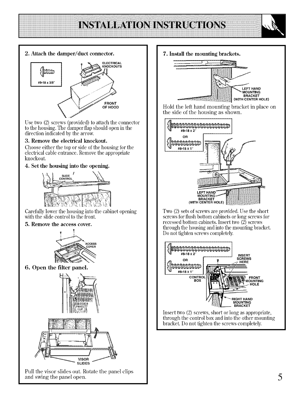
2. Attach the damper/duct connector.
ELECTRICAL
KNOCKOUTS
#8-18 x 3/8"
FRONT
OFHOOD
Use two (2) screws (provided) to attach the connector
to the housing. The damper flap should open in the
direction indicated by the arrow.
3. Remove the electrical knockout.
Choose either the top or side of the housing for the
electrical cable entrance. Remove the appropriate
knockout.
4. Set the housing into the opening.
t \
SLIDE
CONTROL
Carefully lower the housing into the cabinet opening
with the slide control to the front.
5. Remove the access cover.
I
ACCESS
COVER
6. Open the filter panel.
CLIP _
VISOR
SLIDES
Pull the visor slides out. Rotate the panel clips
and swing the panel open.
7. Install the mounting brackets.
Hold the left hand mounting bracket in place on
the side of the housing as shown.
#8-18 x 2"
OR
#8-18 x 1"
LEFT
BRACKET
(WITH CENTER HOLE)
Two (2) sets of screws are provided. Use the short
screws for flush bottom cabinets or long screws for
recessed bottom cabinets. Insert two (2)screws
through the housing and into the mounting bracket.
Do not tighten screws completely.
#8-18X2" INSERT
SCREWS
OR T ,HERE
#_18x1"
CONTROl
BOX FRONT
HOLE
MOUNTING
BRACKET
Insert two (2) screws, short or long as appropriate,
through the control box and into the other mounting
bracket. Do not tighten the screws completely.
5
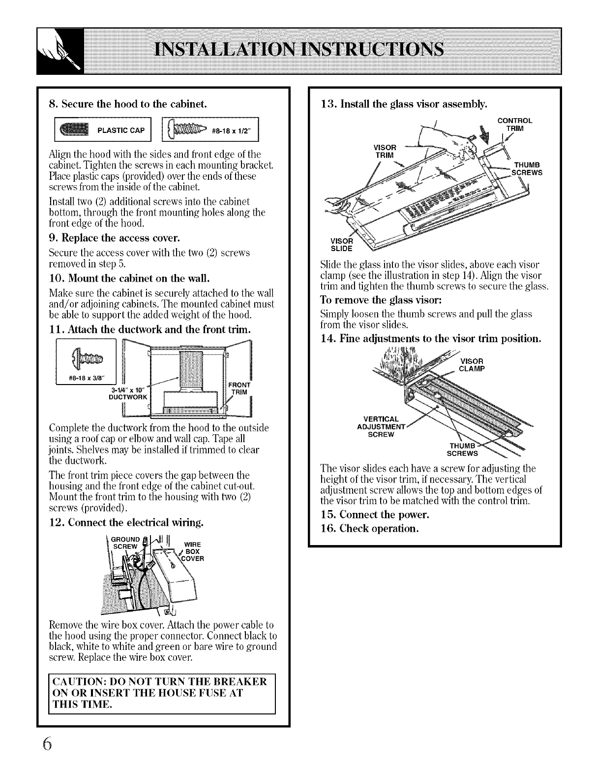
8. Secure the hood to the cabinet.
P.,sT,oc,P [
Align the hood with the sides and front edge of the
cabinet. Tighten the screws in each mounting bracket.
Place plastic caps (provided) over the ends of these
screws from the inside ofthe cabinet.
Install two (2) additional screws into the cabinet
bottom, through the front mounting holes along the
front edge of the hood.
9. Replace the access cover.
Secure the access cover with the two (2) screws
removed in step 5.
10. Mount the cabinet on the wall.
Make sure the cabinet is securely attached to the wall
and/or adjoining cabinets. The mounted cabinet must
be able to support the added weight of the hood.
11. Attach the ductwork and the front trim.
#8-18 x 3/8"
FRONT
3-1/4" x 10" _TRIM
DUCTWORK
Complete the ductwork from the hood to the outside
using a roof cap or elbow and wall cap. Tape all
joints. Shelves may be installed if trimmed to dear
the ductwork.
The front trim piece covers the gap between the
housing and the front edge of the cabinet cut-out.
Mount the front trim to the housing with two (2)
screws (provided).
12. Connect the electrical wiring.
1WIRE
BOX
Removethe wirebox cover.Attachthe powercable to
the hood using the proper connector.Connectblack to
black,whiteto whiteand green or bare wireto ground
screw.Replacethe wirebox cover.
CAUTION: DO NOT TURN THE BREAKER
ON OR INSERT THE HOUSE FUSE AT
THIS TIME.
13. Install the glass visor assembly.
VISOR
TRIM
CONTROL
TRIM
THUMB
SCREWS
VISOR
SLIDE
Slide the glass into the visor slides, above each visor
clamp (see the illustrationin step 14).Align the visor
trim and tighten the thumb screws to secure the glass.
To remove the glass visor:
Simply loosen the thumb screws and pull the glass
from the visor slides.
14. Fine adjustments to the visor trim position.
CLAMP
VERTICAL
SCREW
THUMI
SCREWS
The visor slides each have a screw for adjusting the
height of the visor trim, if necessary. The vertical
adjustment screw allows the top and bottom edges of
the visor trim to be matched with the control trim.
15. Connect the power.
16. Check operation.
6
We'll Be There
With the purchase of your new GE appliance, receive the assurance that if you ever need
infbrmation or assistance fiom GE, we'll be there. All you have to do is call--toll-fiee!
GEAnswer Center
800.626.2000
Whatever your question about any GE major appliance, GE Answer (;enter ®
intormation service is available to hell). Your call--and your question--will
be answered i_romptly and courteously. And you can call any tilne. GE Answer
(_enter ® selwice is open 24 hours a day, 7 (la_:s a week.
In-Home Repair Service
800-GE-CARES(800-432-2737)
AGE consumer service professional will provide expert repair service,
scheduled at a tilne that's coi_velfient for you. Many GE (_oi_stuner Service
COiltl)anv-opei'ated locations oiler volt service today or tOII/OITOW, OI" at your
COlWelfience (7:00 a.in. to 7:00 i).in, weekdays, 9:00 a.in. to 9:00 i).m. Saturdays).
Our tactorv-trained teclmicians know wmr ai)i)liance inside and out--so tnost
rei)airs can be handled in just one visit.
For CustomersWith Special Needs...
800.626.2000
Upon request, (;E will provide
Braille controls for a xarietv of
(;E ai_i_liances, and a brochure to
assist in l)lalming< abarrie>fi'ee
kitchen for persons with limited
mobilit). To obtain these items,
free of char*e call 800.626.2000.
Consumers with impaired hearing or speech who haxe
access to a TDD or a comentional teletyl)ewriter ma)
call 800-TDD-GEAC (800-833-4322) to request
infort/tation or serxice.
Service Contracts
800-626-2224
You can have the secure teeling that (;E Consumer Service will still be there
alter your warranty expires. Purchase a GE contract while wmr warranty is still
in etti_ct and you'll receive a substantial discount. With a multii)le-year contract,
win're assured of flmue service at today's prices.
Parts and Accessories
800-626-2002
Individuals qualified to service their own appliances
can have parts or accessories sent directly to their holne.
The GE parts systetn provides access to over 47,000
parts...and all GE Genuine Renewal Parts are fully
warranted. VISA, Master(_ard and Discover cards
are accepted.
User maintenance instructions contained in this guide
cover procedures intended to be performed by any user.
Other servicing generally should be referred to qualified
service personnel. Caution must be exercised, since
improper servicing may cause unsafe operation. 7
=r
W
W
=
=
_o
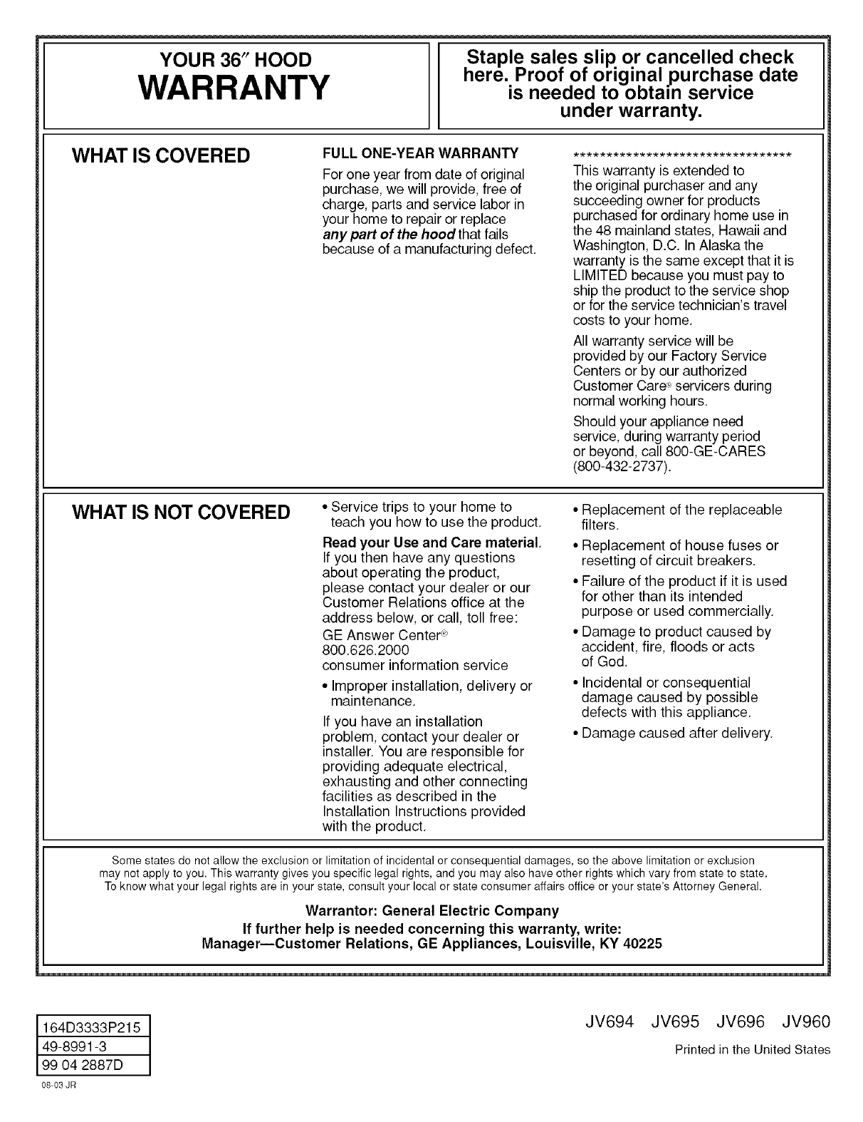
YOUR 36" HOOD
WARRANTY Staple sales slip or cancelled check
here. Proof of original purchase date
is needed to obtain service
under warranty.
WHAT IS COVERED FULL ONE-YEAR WARRANTY
For one year from date of original
purchase, we will provide, free of
charge, parts and service labor in
your home to repair or replace
any part of the hood that fails
because of a manufacturing defect,
This warranty is extended to
the original purchaser and any
succeeding owner for products
purchased for ordinary home use in
the 48 mainland states, Hawaii and
Washington, D.C, In Alaska the
warranty is the same except that it is
LIMITED because you must pay to
ship the product to the service shop
or for the service technician's travel
costs to your home,
All warranty service will be
provided by our Factory Service
Centers or by our authorized
Customer Care .>servicers during
normal working hours.
Should your appliance need
service, during warranty period
or beyond, call 800-GE-CARES
(800-432-2737).
WHAT IS NOT COVERED • Service trips to your home to
teach you how to use the product.
Read your Use and Care material,
If you then have any questions
about operating the product,
please contact your dealer or our
Customer Relations office at the
address below, or call, toll free:
GE Answer Center _
800,626,2000
consumer information service
• Improper installation, delivery or
maintenance,
If you have an installation
problem, contact your dealer or
installer, You are responsible for
providing adequate electrical,
exhausting and other connecting
facilities as described in the
Installation Instructions provided
with the product,
• Replacement of the replaceable
filters,
• Replacement of house fuses or
resetting of circuit breakers,
• Failure of the product if it is used
for other than its intended
purpose or used commercially,
• Damage to product caused by
accident, fire, floods or acts
of God.
• Incidental or consequential
damage caused by possible
defects with this appliance,
• Damage caused after delivery,
Some states do not allow the exclusion or limitation of incidental or consequential damages, so the above limitation or exclusion
may not apply to you. This warranty gives you specific legal rights, and you may also have other rights which vary from state to state.
To know what your legal rights are in your state, consult your local or state consumer affairs office or your state's Attorney General.
Warrantor: General Electric Company
If further help is needed concerning this warranty, write:
Manager--Customer Relations, GE Appliances, Louisville, KY 40225
164D3333P215
49-8991-3
99 04 2887D
08_03 JR
JV694 JV695 JV696 JV960
Printed in the United States
