GE JVM1790BK01 User Manual MICROWAVE Manuals And Guides L0523298
GE Microwave/Hood Combo Manual L0523298 GE Microwave/Hood Combo Owner's Manual, GE Microwave/Hood Combo installation guides
User Manual: GE JVM1790BK01 JVM1790BK01 GE MICROWAVE - Manuals and Guides View the owners manual for your GE MICROWAVE #JVM1790BK01. Home:Kitchen Appliance Parts:GE Parts:GE MICROWAVE Manual
Open the PDF directly: View PDF ![]() .
.
Page Count: 48
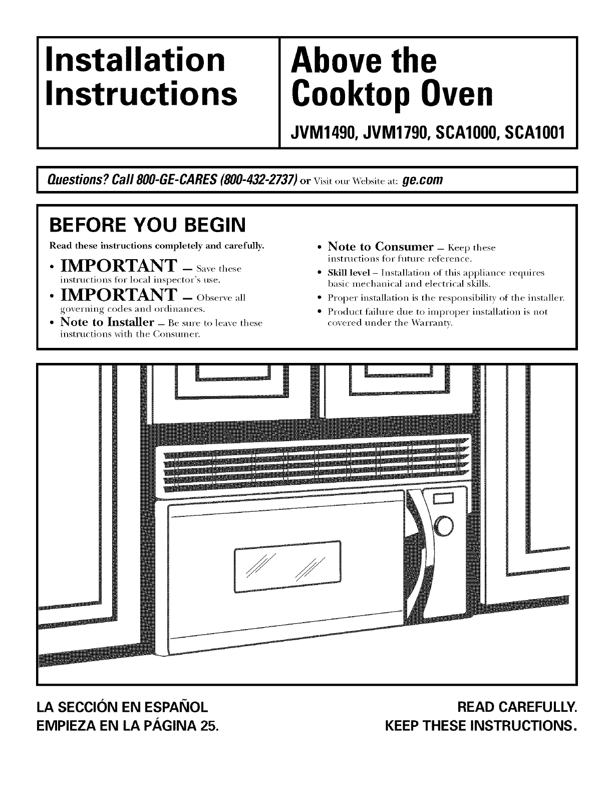
Installation
Instructions Abovethe
CooktopOven
JVM1490,JVM1790,SCAI000,SCAI001
Questions?Call 800-GE-CARES(800-432-2737)or visitour _ ebsite at: ge.com I
BEFORE YOU BEGIN
Read these instructions completely and carefully.
• IMPORTANT - S.,e_hese
instructions for local inspector's use.
•IMPORTANT -Obse,,e.ll
go_,ei'iliil o codes _lIl(1 oI'diIl_lIlCes.
• Note to Installer -Be sure to lea',e these
instructions with the (_onsumer.
o
o
o
o
Note to Consumer _ Keep these
instructions for future reterence.
Skill level -Installation of this appliance reqtfires
basic mechanical and electrical skills.
Proper installation is the responsibility of the installer.
Product thilure due to improper installation is not
coxered trader the _arrantx.
LA SECCION EN ESPAI_OL
EMPIEZA EN LA PAGINA 25.
READ CAREFULLY.
KEEP THESE INSTRUCTIONS.
Installation Instructions
CONTENTS
General information
hnportant Safety Instructions .................................. 3
Electrical Requirements .......................................... 3
Hood Exhaust ...................................................... 4, 5
Damage -Shipment/InstaJlation .............................. 6
Parts Included. ......................................................... 6
Tools You Will Need ................................................ 7
Mounting Space ...................................................... 7
Step-by-step installation guide
Placement of Mounting Plate ............................ 8-10
Removing tire Mounting Plate ...................... 8
Finding the _4all Studs ................................. 8
Determining _.lll Plate l.oration .................. 9
Aliguiug the _4hll Plate ............................... 10
Installation Types .................................. 11-22
[]Outside Top ............................
Exhaust 12-14
Attach Mounting Plate to W;dl ....... 12
Preparation of Top Cabinet .......... 13
Checking 1or Proper Damper
()peration ............................................ 13
Mount the Oveu .................... 13, 14
Ac!just the Exhaust Adaptor .......... 14
Connerting Durtwork .......................... 14
_ ()utside Back Exhaust 15-18
Preparing Rear _'V;dl for
Outside Bark Exhaust .......................... 15
Attach Mounting Plate U>_4"01 ...... 15, 16
Preparation of Top Cabinet .......... 16
Adapting Blower tot Outside
Back Exhaust.. .............................. 16, 17
Mount the Oveu .................................. 18
Redrculating ........................................ 19-22
Attach Mounting Plate to _4.fll ....... 19
Preparation of Top Cabinet .......... 19
Adapting Blower
for Redrrulation ......................... 20, 21
Mount the Oveu .................... 21, 22
Installing the Charcoal Filter ...... ........ 22
Before You Use Your Oven .................................. 23
Seccion en Espafiol ........................................ 25-47
2
Installation Instructions
mMPORTANT SAFETY mNSTRUCT ONS
CAWFION: For personal safety, the momlting surface
must be capable of supporting the cabinet load, in
addition to the added weight of this 62%85 pound
product, plus additional oven loads of up to 50 pounds
or a total weight of 117_135 pounds.
CAIYFION: For personal safety, this product c_ot
be installed in cabinet arrmlgements such as an island or
aperfinsuia. It must be mounted to BOTH atop cabinet
AND a wall.
NOTE: For easier insta]iation and personal safety, it is
recommended that two people install tt_s product.
IMPORTANT PLEASE R1LM) CARFFULL_: FOR
PERSONAL SAFETY; THIS APPLIANCE MUST BE
PROPERLY GROUNDED TO AVOID SEVERE OR
FNFAL SHOCK.
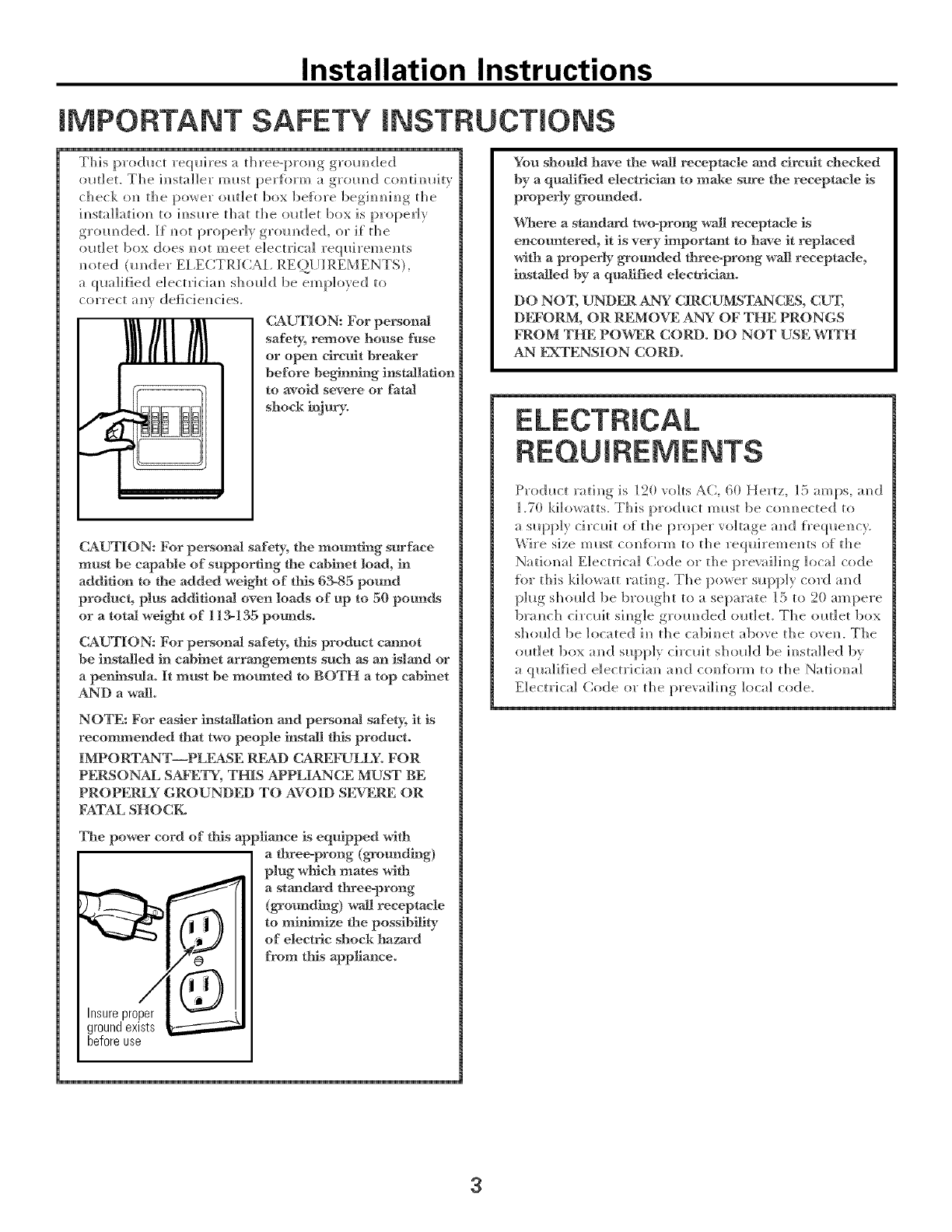
The power cur'd of this app]iance is equipped with
a three=prong (grounding)
plug which mates with
a standard three=prong
(gromlding) wail receptacle
to mininlize the possibility
of electric shock hazard
from tiffs app]iance.
Insureproper
groundexists
beforeuse
Yon should have the wail receptacle and circuit checked
by aqualified electrician to make sure the receptacle is
properly grounded.
Where a standard two-prong wall _eceptade is
encountered, it is very inlportant to have it replaced
with a properly grounded three=prong wail receptacle,
installed by aqualified electridan.
DO NO% UNDER ANY CIRCUMST_CES, CU_[;
DI_"ORM, OR REMOVE ANY OF THE PRONGS
FROM THE POWER CORD. DO NOT USE ¼rITH
AN FXTENSION CORD.
ELECTRICAL
REQUIREMENTS
Product rati]/g is 120 volts AC, 60 Hertz, [5 amps, am]
1.70 kilowatts. This product must be co]/m/ected to
a slq_p]} ci]mdt o{ the propervoItq<,e_ am] {reql_e]/c}.
\_ire si zem Ilst CO]/['()]q]/ It) the req Hi rein el/ts of the
Natiomd Electrical Code or tile [)revaiIim/g, local code
for this kilowatt mtim/g. The [)o]ver sIl[)pl_ co]'d amid
>lug sholdd be lu'm]<,ht to a separate 15 to 90= ampere
bra_]c]] circlfit si_]g]e groin]deal ola]et. The ]mt]et box
should be located i_i tile cabim/et above tile ore]/. Tile
outlet box am] suppI} circuit sho_ld be ira/stalled bv
a qlmIilied eIectricim/am[ coului'm to the Nati]mal
Electrical Code ur the prevaili_/g local code.
3
Installation Instructions
HOOD EXHAUST
NOTE: Read these next two pages tufty if you plml to vent your exhaust to the outside.
If you plml to recirculate the air back into the room, proceed to page 6.
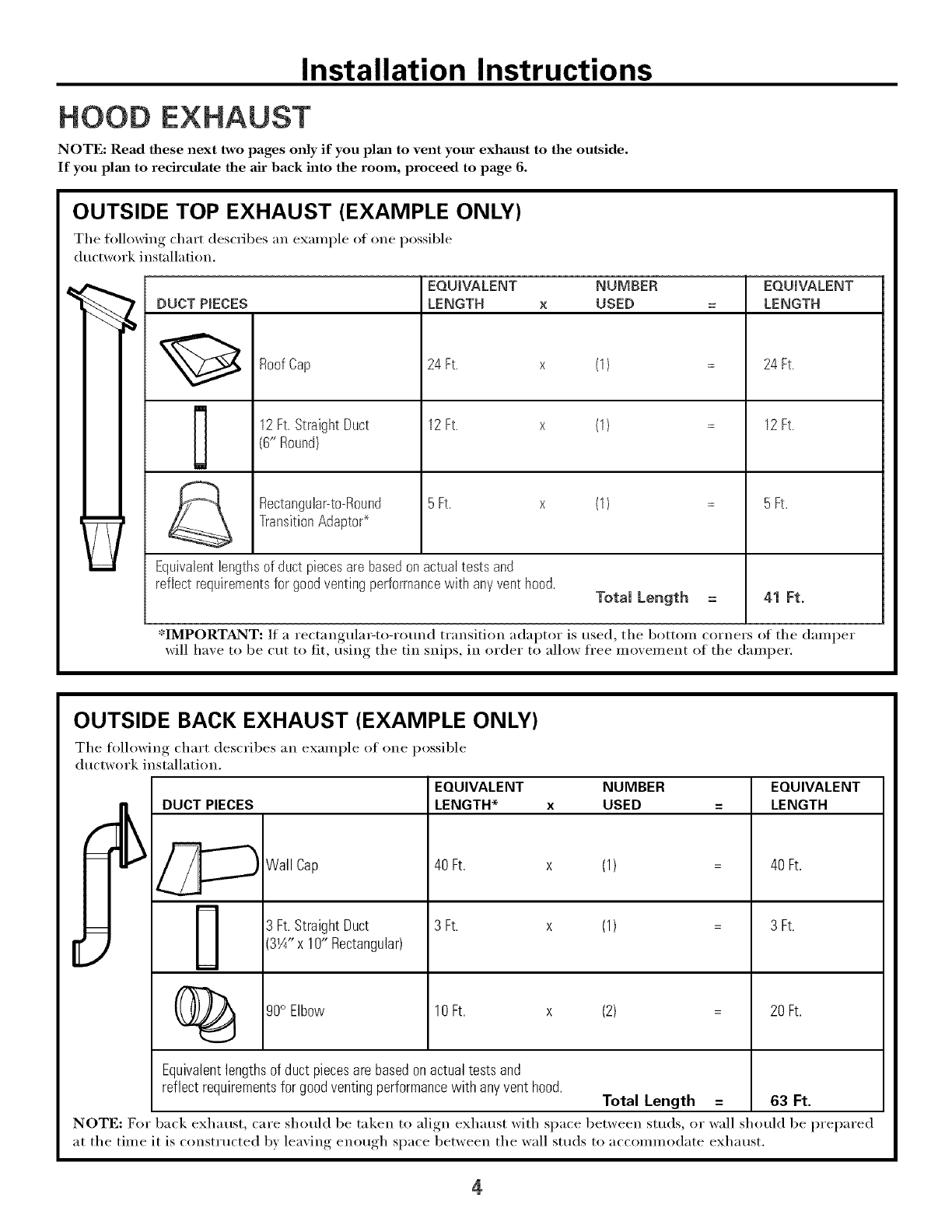
OUTSIDE TOP EXHAUST (EXAMPLE ONLY)
The following chart describes an example ot one possible
ductwork instnllation.
DUCT P_ECES
EQUIVALENT NUMBER
LENGTH x USED
RoofCap 24 Ft. x
12Ft.StraightDuct 12Ft. x
(6" Round)
RectanguhFto-Round 5Ft. x
TransitionAdaptor*
Equivalentlengthsof duct piecesare basedonactualtests and
reflect requirementsfor goodventingperformancewith anyventhood.
(1)
(1)
(1)
Total Length
EQUIVALENT
LENGTH
24 Ft.
12Ft.
5Ft.
41 Ft.
*IMPORTANT: If a rectangula_to-rotmd transition adaptor is used, the bottom corners of the damper
will ha_e to be cut to fit, usim,._ the tin snips, in order to allow free mo'.ement of the damper.
OUTSIDE BACK EXHAUST (EXAMPLE ONLY)
The following chart describes an example ot one possible
ductwork installation.
[DUC_ PIECES
_Wall Cap
(_ 90° Elbow
EQUIVALENT NUMBER EQUIVALENT
LENGTH* x USED = LENGTH
40 Ft. x (1) 40 Ft.
3 Ft. x (1)3 Ft.StraightDuct
3W' x 10" Rectangular)
10Ft. x (2)
3 Ft.
20Ft.
Equivalent lengths of duct pieces are based on actual tests and
reflect requirements for good venting performance with any vent hood. Total Length = 63 Ft.
NOTE: For back exhaust, care should be taken to align exhaust with space between studs, or wall should be prepared
at the time it is constructed by leaving enough space between the wall studs to accommodate exhaust.
4
Installation Instructions
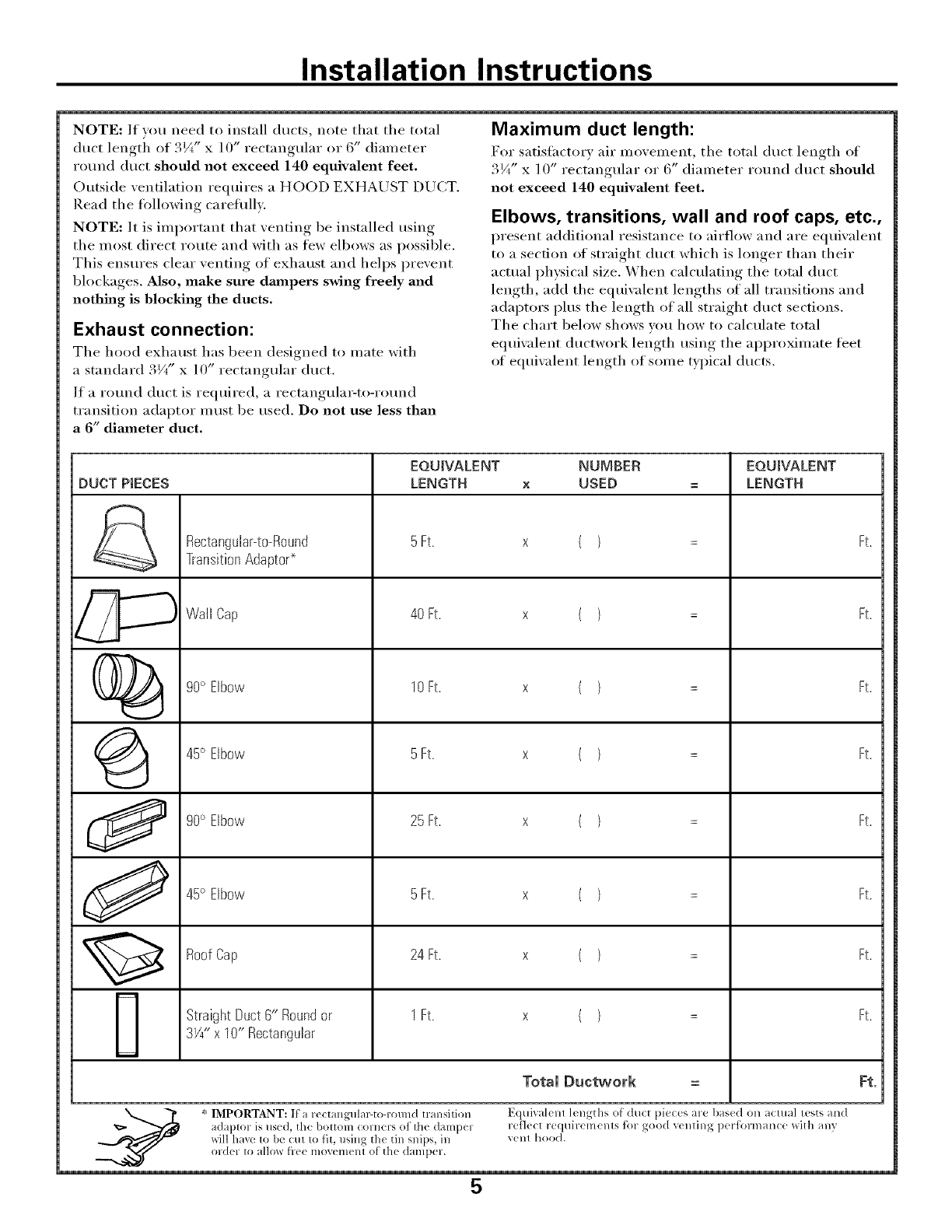
NOTE: If you need to install ducts, note that the total
duct lengti_ of 3¼" x ] O" rectangular or 6" (liameter
round duct should not exceed 140 equivalent feet.
Outside ventilation requires a HOOD EXHAUST DUCT.
Read the following careflfllv.
NOTE: It is important that venting be installed using
the most direct route and with as few elbows as possible.
This ensm'es clear venting of exhaust and helps prevent
blockages. Also, make sure dampers swing freely and
nothing is blocking the ducts.
Exhaust connection:
The hood exhaust has been designed to mate with
a standard 3Vt" x 10" rectangular duct.
If a round duct is required, a rectangula>to-rotmd
transition adaptor must be used. Do not use less than
a 6" diameter duct.
Maximum duct length:
For satisfiwtorv air movement, the total duct length of
3¼" x ] 0" rectangular or 6" diameter round duct should
not exceed 140 equivalent feet,
Elbows, transitions, wall and roof caps, etc.,
present additional resistance to airflow and are equivalent
to a section of straight duct which is hinter than their
actual physical size. When calculating the total duct
length, add the equiwdent lengths of all transitions and
adaptors plus the length of all straight duct sections.
The chart below shows w)u how to calculate total
equivalent ductwork length using the approximate teet
of equiwdent length of some typical ducts.
EQUIVALENT NUMBER EQUIVALENT
DUCT PIECES LENGTH x USED = LENGTH
Rectangular-to-Round 5 Ft. x ( ) =Ft.
Transition Adaptor
Wall Cap 40 Ft. x ( ) = Ft.
C)_ go° Elbow 10 Ft. x ( ) =Ft.
{_ 45° Elbow 5 Ft. x ( ) = Ft.
90° Elbow 25 Ft. x ( ) =Ft.
J 45° Elbow 5Ft. x ( ) =Ft.
Roof Cap 24 Ft. x ( ) = Ft.
Straight Duct 6" Round or 1 Ft. x ( ) = Ft.
3W' x 10" Rectangular
Total Ductwork = Ft.
* IMPORTANT: If' a re( tangulal_to-round transilion E(ltfival( nl 1_ ngths of" du(t pieces are bas(d on aclual tests and
adaplor is use(l, the boltonl colners of lhe (]0Jllp( i l-(:_]ect reqtfir( m( nls lk)r good v( nling performan(e with any
_dll have I0 b( {:tit I1) fit, llSillg the till snips, ill V(llt hood.
(}lXiel I(} allo_ flee lllOV(>l)lelll Of' the ([HlllpeF.
5
Installation Instructions
-SHIPMENT/
mNSTALLATmON
®]If the _it is damaged in shipmenL remr_] the
m_]t to the store im_which it w_s b<mght fi)r repair
ov rep] a ce]_ em_t_
® If the unit is damaged by the customer, repair or
rep];_ceme]_t is the respom_sibi]ity of the cl_stomer.
® ]_f the unit is damaged by the installer (if other
tbam_ the cllstomer), repair or rep]_ceme]_[ mils[
be m:tde by :trram?geme]?[ betweeN? cllstomer am?(]!
im_sta]]er.
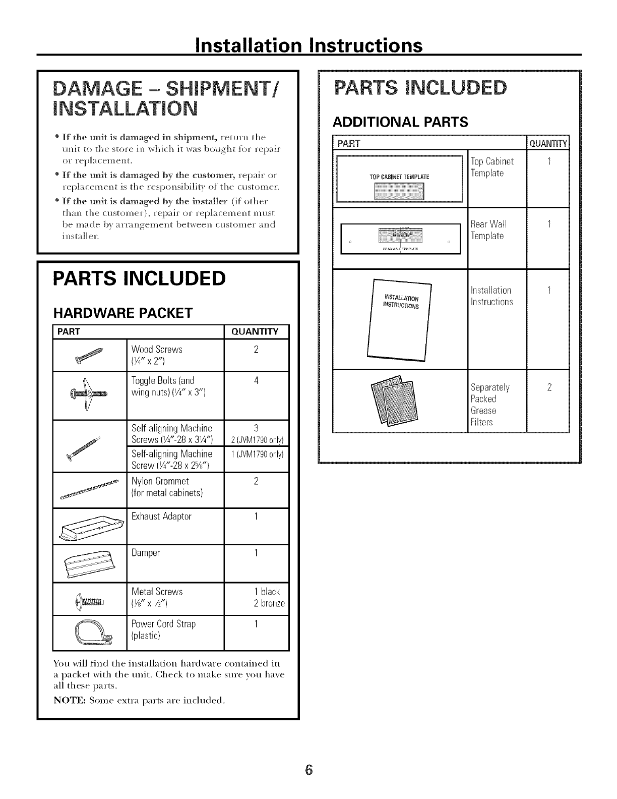
PARTS INCLUDED
HARDWARE PACKET
PART QUANTITY
WoodScrews 2
(¼" x2")
ToggleBolts(and 4
wing nuts)(¼" x 3")
Self-aligningMachine
Screws(¼"-28x 3¼")
Self-aligningMachine
Screw(¼"-28 x 2%")
NylonGrommet
(for metalcabinets)
3
2 (JVM1790only)
1 (JVM1790only)
2
ExhaustAdaptor 1
Damper 1
MetalScrews 1 black
{1_" X I_ 'v) 2 bronze
PowerCordStrap 1
(plastic)
You will find the installation hardware contained in
a packet with the trait. Check to make sure you have
all these parts.
NOTE: Some extra parts are included.
PARTS mNCLUDED
ADDITIONAL PARTS
TOPCABINET TENPLATE
NSTALLA?ION
iNSTRUCTIONS
TopCabinet
Template
RearWall
Template
Installation
Instructions
Separately
Packed
Grease
Filters
QUANTIFY
1
6
Installation Instructions
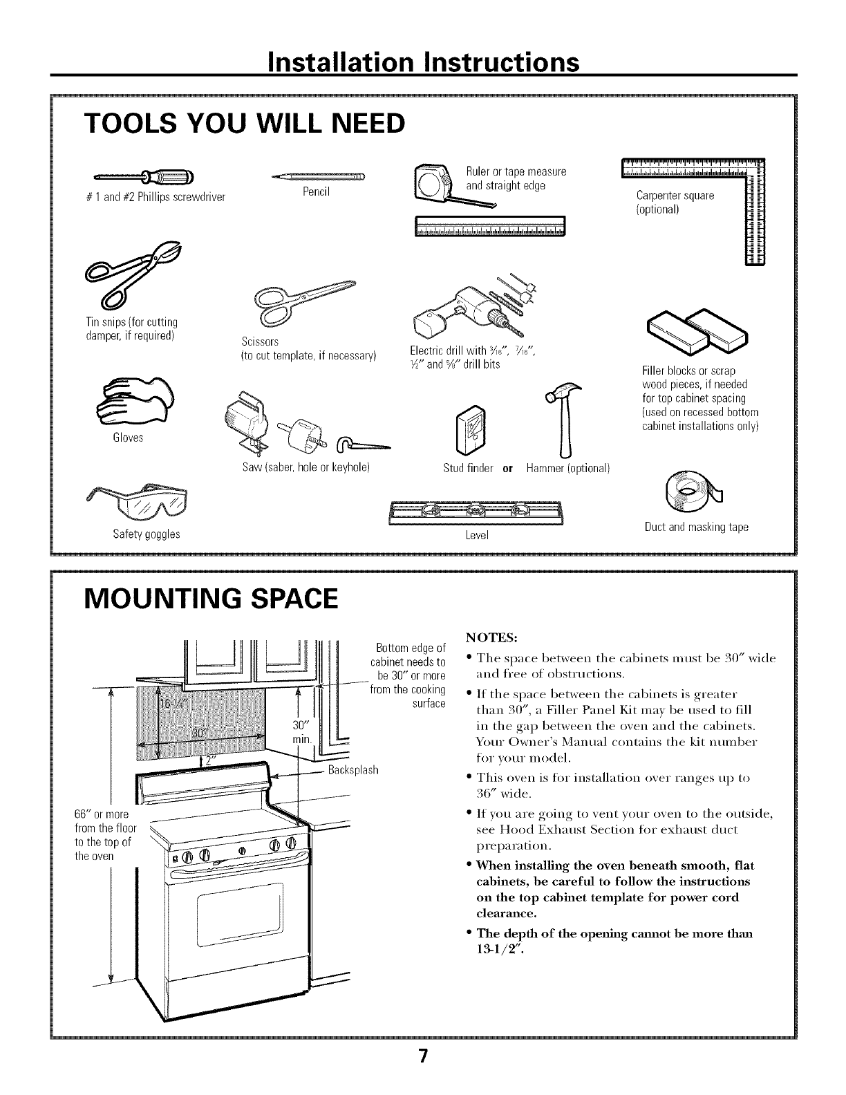
TOOLS YOU WILL NEED
# 1 and#2 Phillipsscrewdriver
Tinsnips(forcutting
damper,if required)
Pencil
Scissors
(to cut template,if necessary)
Rulerortape measure
aightedge
Electricdrill with 3/16",7716,"
1½-and%" drill bits
Gloves
Studfinder or Hammer(optional)
Carpentersquare
(optional)
Fillerblocksor scrap
woodpieces,if needed
for top cabinetspacing
(usedonrecessedbottom
cabinetinstallationsonly)
Saw(saber,holeor keyhole)
L J Ductandmaskingtape
Safetygoggles Level
MOUNTING SPACE
66" ormore
fromthe floor
to the top of
theoven
\
Bottomedgeof
cabinetneedsto
be30" or more
fromthe cooking
surface
Backsplash
NOTES:
• The space between the cabinets must be 30" wide
and fl'ee of obst_ uctions.
" If the space between the cabinets is greater
than 30", a Filler Panel Kit may be used to fill
in the gap between the oven and the cabinets.
Your Owner's Manual contains the kit nmnber
foI" VOtlI" model.
" This oven is fin" installation over ranges up to
36" wide.
" If vou are going to vent v(mr oven to the outside,
see Hood Exhaust Section tot exhaust duct
preparation.
" When installing the oven beneath smooth, flat
cabinets, be careful to follow the instructions
on the top cabinet template for power cord
clearance.
" The depth of the opening cmmot be more thml
13-1/2".
7
Installation Instructions
I-]PLACEMENT OF THE MOUNTING PLATE
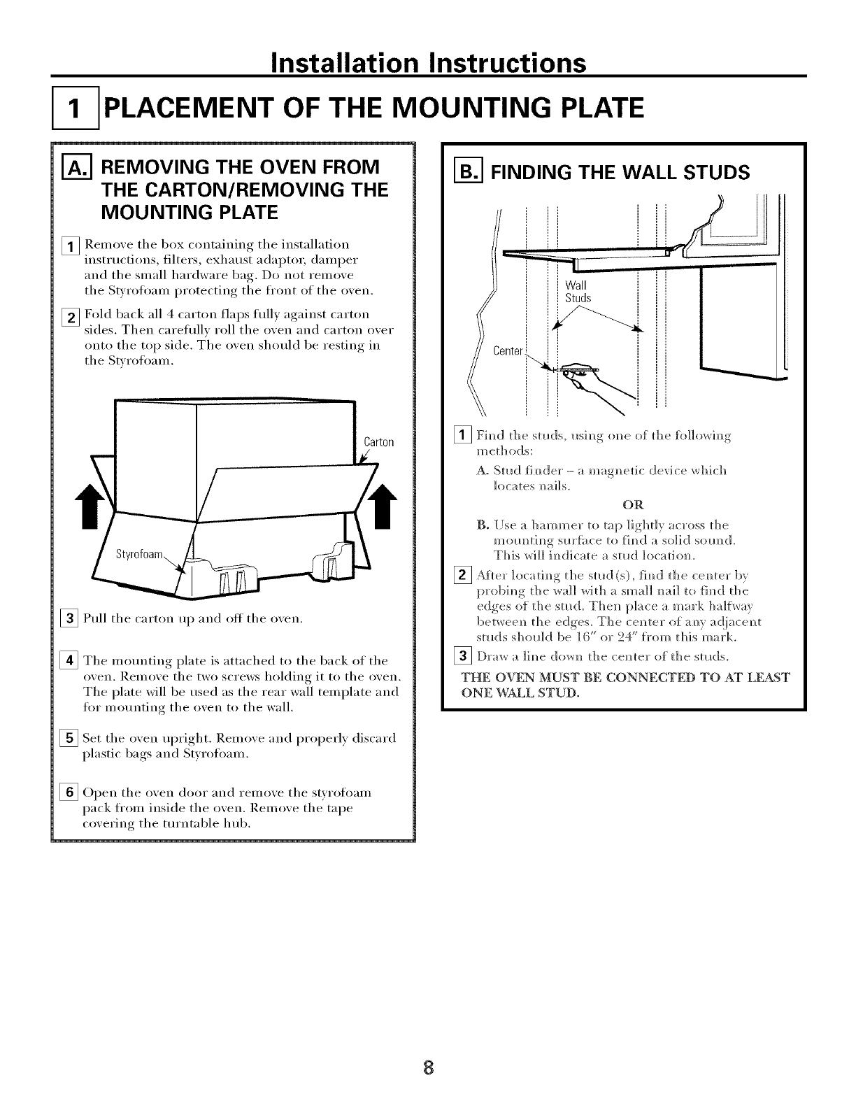
1"_ REMOVING THE OVEN FROM
THE CARTON/REMOVING THE
MOUNTING PLATE
_ Remoxe the box containing the installation
instructions, filters, exhaust adaptor, damper
and the small hardware bag,. Do not remoxe
the Styrofoam I_r°tecting, the front of the oxen.
[] Fold back all 4 carton flaps full) against carton
sides. Then careflfllx roll the oxen and carton oxer
onto the top side. T'he oxen should be restino, _in
the Styrofoam.
Carton
_Pull the carton up and off the oxen.
[]The motmting plate is attached to the back of the
oxen. Remoxe the two screws holding it to the oxen.
The plate will be used as the rear wall template and
for mounting the oxen to the wall.
[]Set the oven upri *lit Remoxe and properly discard
plastic bags and Styrofoam.
[Open the oxen door and remoxe the styrofoam
pack from inside the oxen. Remoxe the tape
coxering the turntable hub.
I-_ FINDING THE WALL STUDS
enter_
[] Fim_d t]_e studs, usim_g <me of t]_e fo]]OVTim?g
m e[]] (>ds:
A. Stud timider- a magnetic device which
locates m_ai]s.
OR
B. [Ise a hammer to tap ]ighdy across die
mom_tim_g sm'Ii_ce to fim_d a solid som_d.
This will im_dicate a stud ]ocatiom
_Afler the fi_id the bv
]ocatim_g stLld(s), cem_ter
probi_*g the wall with a small m_ailto }h_d the
edges o{ the stud. TheN_ place a mark ha]f\_au
betweeN_ the edges. The cel_ter of am_y a(]jaceN_t
studs sholdd be ]6" or 24" f}'om this mark,
_ Draw a ]im_e dow]_ the cem_ter of the st_ds.
THE OVEN MUST BE CONNECTED TO AT LEAST
ONE WALL STUD.
8
Installation Instructions
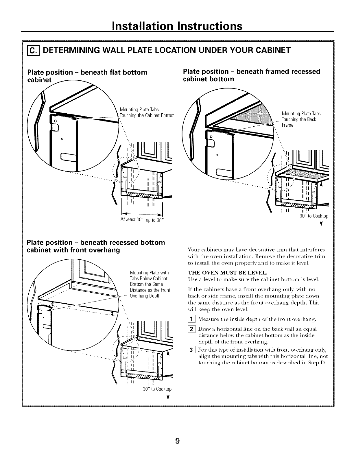
DETERMINING WALL PLATE LOCATION UNDER YOUR CABINET
Plate position - beneath flat bottom
cabinet Plate position - beneath framed recessed
cabinet bottom
Mounting Plate Tabs
_gthe Cabinet Bottom
At least 30", up to 3B"
Mounting Plate Tabs
Touching the Back
Frame
II
30"to Cooktop
Plate position - beneath recessed bottom
cabinet with front overhang
Mounting Plate with
Tabs Below Cabinet
Bottom the Same
Distance as the Front
g Depth
LL
Ill
30" to Cool<top
Your cabinets may have decorative trim that interferes
with the oven installation. Remove the decorative trim
to install the oven i)roperly and to make it level.
THE OVEN MUST BE LEVEL
ILlse a level to make sure the cabinet bottom is level.
If the cabinets have a fl'ont overhang only, with no
back or side fl'ame, install the mounting plate down
the same distance as the fl'ont overhang depth. This
will kee I) the oven level.
[]Measure the inside depth of the fl'ont overhang.
Draw a horizontal line on the back wall equal
distance below the cabinet bottom as the inside
depth of the fi'ont overhang.
[]For this t):pe of installation with fi'ont overhang only,
align the mounting tabs with this horizontal line, not
touching the cabinet bottom as described in Step D.
9
Installation Instructions
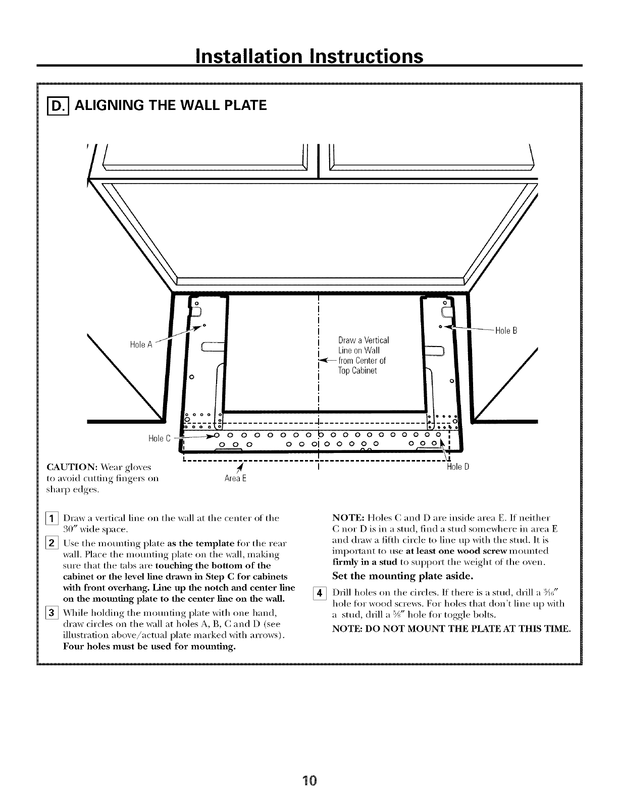
ALIGNING THE WALL PLATE
Drawa Vertical
LineonWall
-<--from Centerof
TopCabinet
HoleC
CAUTION: _,,Veargloves
to axoid cutting fingeI5 on
sharp edges.
o oo
0 0 0 0 0 0 0 0 0 0 0 0 0 0 0 0 0
o o o o o oio o o oo ooo
AreaE
H01eD
[]Draw a vertical line on tile wall at tile center of tile
30" wide space.
[]Use tile mounting plate as the template for tile rear
wall. Place the mo/mting plate on the wall, making
sure that the tabs are touching the bottom of the
cabinet or the level line drawn in Step C for cabinets
with front overhm_g. Line up the notch mid center line
on the mounting plate to the center line on the wall.
_ \._q/ile holding the mounting plate with one hand,
draw drcles on the wall at holes A, B, C and D (see
illustration above/actual plate marked with arrows).
Four holes must be used for mounting.
[]
NOTE: Holes C and D are inside area E. If neither
C nor D is in a stud, find a stud somewhere in area E
and draw a filil/ circle to line up with the stud. It is
important to use at least one wood screw mounted
firmly in a stud to support tile weight ot tile oven.
Set the mounting plate aside.
Drill holes on the drcles. If there is a stud, drill a '_A¢_"
hole tot wood screws. For holes that don't line up with
a stud, (hill a %" hole fin" toggle bolts.
NOTE: DO NOT MOUNT THE PLATE AT THIS TIME.
10
Installation Instructions
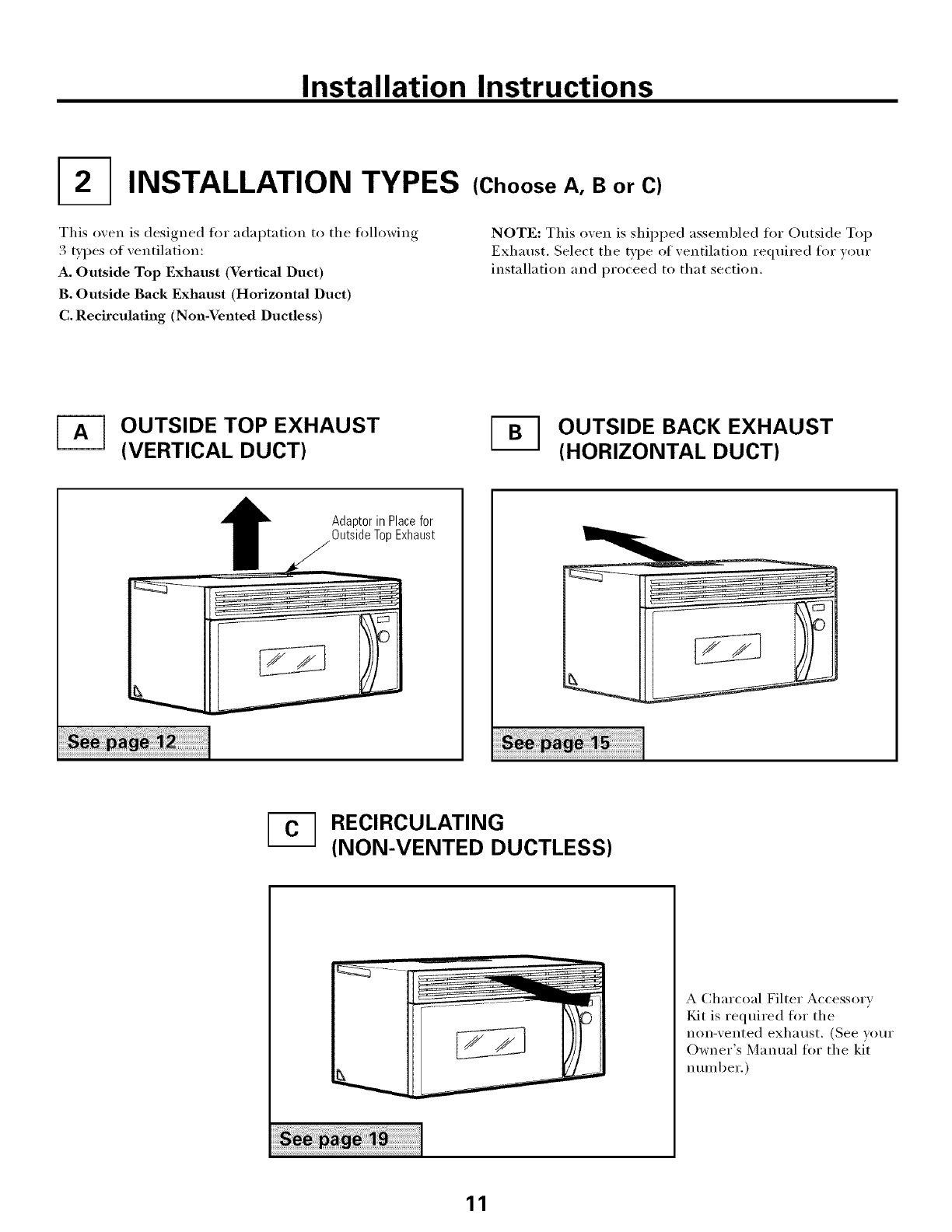
I2-] INSTALLATION TYPES
This oven is designed h>r adaptation to the fi>llowing
3 types of ventilation:
A. Outside Top Exhaust (Vertical Duct)
B. Outside Back Exhaust (Horizontal Duct)
C. Recirculating (Non-Vented Ductless)
(Choose A, B or C)
NOTE: This oven is shiI)ped assembled fin" Outside Top
Exhaust. Select the type of xentilation required for }our
installation and proceed to that section.
OUTSIDE TOP EXHAUST
(VERTICAL DUCT) OUTSIDE BACK EXHAUST
(HORIZONTAL DUCT)
1Adaptorin Placefor
OutsideTopExhaust
_-] RECIRCULATING
(NON-VENTED DUCTLESS)
A Charcoal Filter Accessory
Kit is required fin" the
non-vented exhaust. (See your
Owner's Manual fin" the kit
number.)
11
Installation Instructions
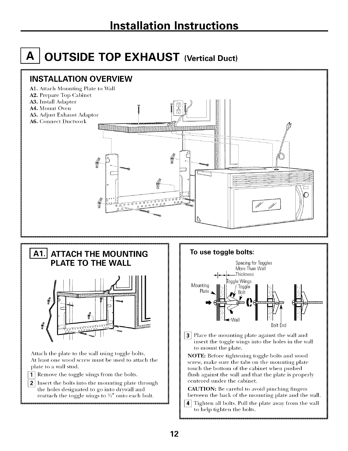
OUTSIDE TOP EXHAUST (Vertical Duct)
INSTALLATION OVERVIEW
A1. Attach Mounting Plate to Wall
A2. Prepare Top Cabinet
A3. Install Adapter
A4. Mount Oven
A5, A(!just Exhaust Adaptor
A6, Connect Ductwork
I-_ ATTACH THE MOUNTING
PLATE TO THE WALL
Attach the plate to the wall using toggle bolts.
At least one wood screw IlltlSt be used to attach the
plate to a wall stud.
[]Remove the toggle wings fl'om the bolts.
[]Insert the bolts into the mounting plate through
the holes designated to go into drDvall and
reattach the toggle wings to :Y," onto each bolt.
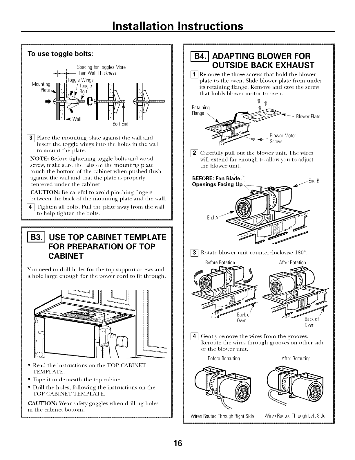
To use toggle bolts:
Spacingfor Toggles
MoreThanWall
-@H,_i*_Th ckness
Mounting
Plate,
BoltEnd
_ Place the mounting plate against the wall and
insert the toggle wings into the holes in the wall
to motmt the plate.
NOTE: Betore tightening toggle bolts and wood
scre_, make sm'e the tabs on the mounting plate
touch the bottom of the cabinet when ptlshed
flush against the wall and that the plate is properly
centered trader the cabinet,
CAUTION: Be careflfl to axoid I)inchin'*_ fingers
between the back of the motmting plate and the wall,
_ Tighten all bolts, Pull the plate awax from the wall
to help tighten the bolts,
12
Installation Instructions
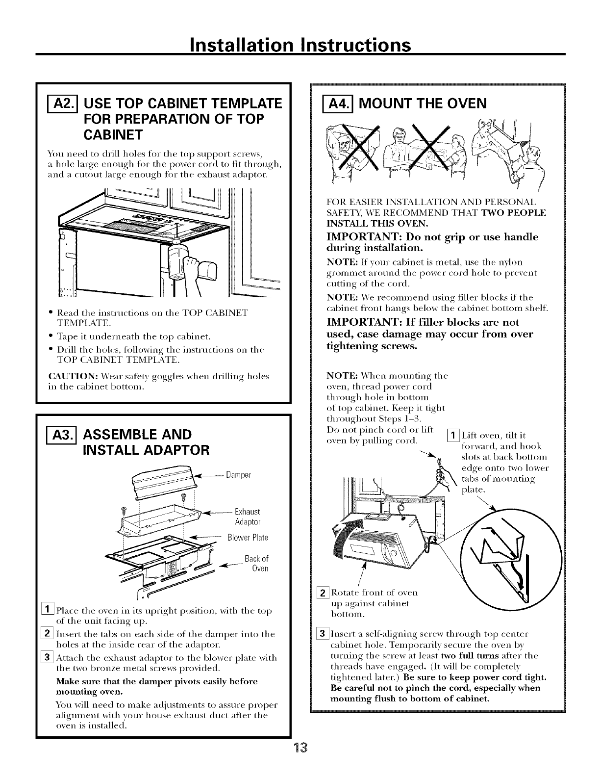
I-_ USE TOP CABINET TEMPLATE
FOR PREPARATION OF TOP
CABINET
You need to drill holes for the top support screws,
a hole large enough for the power cord to fit thr(m ,h
and a cutout large enough fi_r tile exhaust adaptor.
" Read tile instructions on tile TOP CABINET
TEMPLATE.
" Tape it tmderneath the top cabinet.
" Drill the holes, following the instructions on the
TOP CABINET TEMPLATE.
CAUTION: Wear safet} goggles when drilling holes
in tile cabinet bottom.
ASSEMBLE AND
INSTALL ADAPTOR
Damper
Exhaust
Adaptor
_,_.:__ BlowerPlate
Bac
[] Place tile oven in its ul)right position, with tile top
of tile unit tacing up.
_Insert the tabs on each side of the damper into the
holes at the inside rear of the adaptor.
_ Attach tile exhaust adaptor to the blower plate with
tile two bronze metal screws provided.
Make sure that the damper pivots easily before
mounting oven.
You will need to make a(!iustments to assure proper
alignment with wmr house exhaust duct atter tile
oven is installed'.
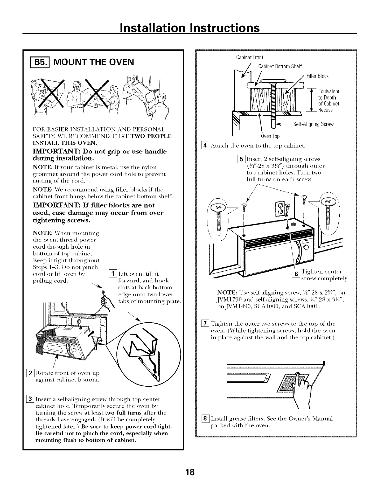
I-_ MOUNT THE OVEN
FOIl EASIER INSTAI,IATION AND PERSONAl,
SAFETY, WE RECOMMEND THAT TWO PEOPLE
INSTALL THIS OVEN.
IMPORTANT: Do not grip or use handle
during installation.
NOTE: If your cabinet is metal, use tile nylon
grolUll/et _lro/lnd tile [)()wet" cord hole to l)revent
cutting of tile cord.
NOTE: _4'e recommend using filler blocks if tile
cabinet fl'ont hangs below the cabinet bottom shell
IMPORTANT: If filler blocks are not
used, case damage may occur from over
tightening screws.
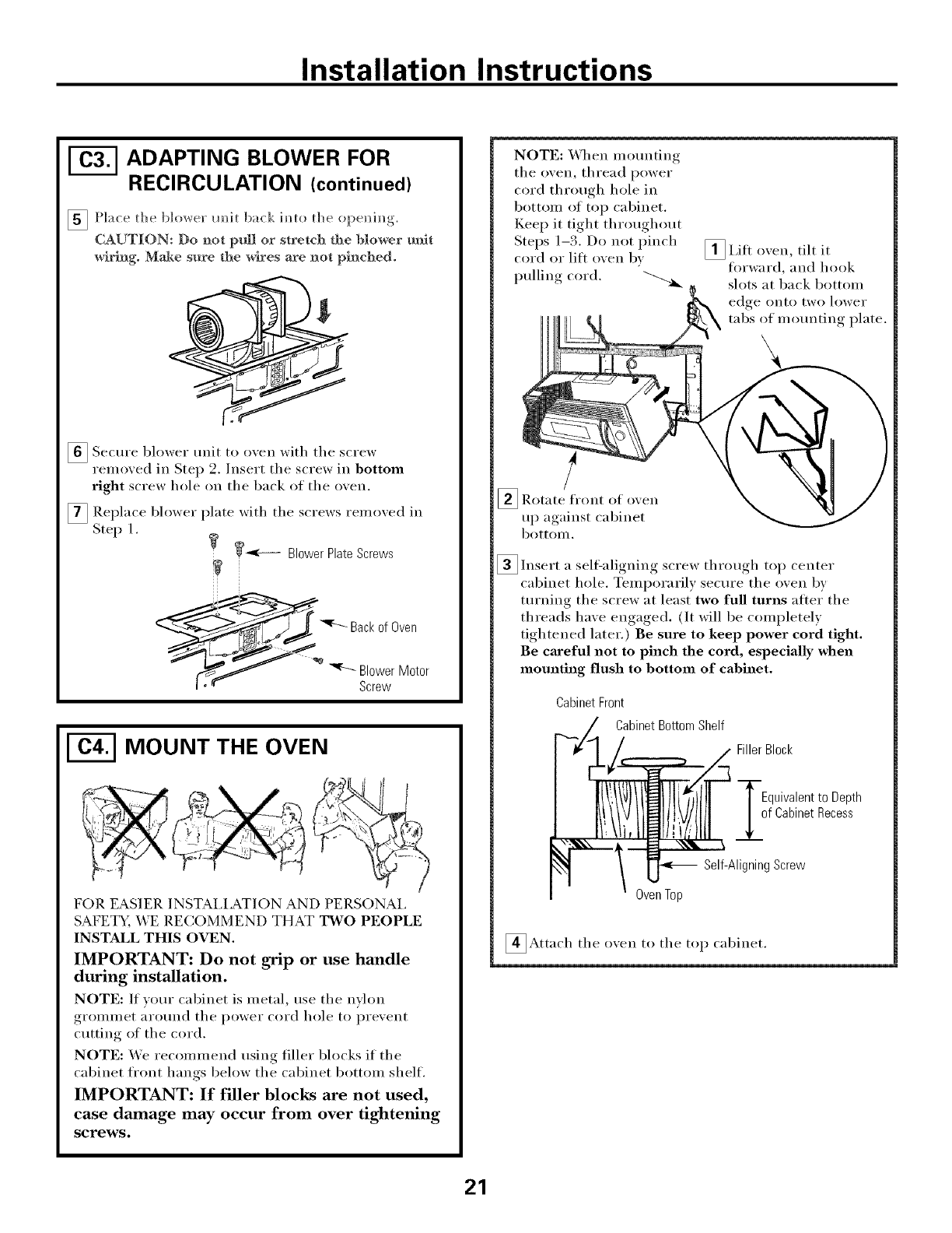
NOTE: When mo/mting tile
oven, thread power cord
through hole in bottom
of top cabinet. Kee I) it tight
throughout Steps 1-3.
Do not pinch cord or lift
oven by pulling cord. _I,ifl oven, tilt it
fl_rward, and hook
slots at back bottom
edge onto two lower
tabs of mounting
plate.
/
_Rotate front of o_en
up against cabinet
bottolll.
],_ throughInsert a self-aligniw* screw , top center
cabinet hole. Temporarily secure the oven b)
turning tile screw at least two full turns atter tile
threads haxe ew*aged._, (It will be completel)
tightened later.) Be sure to keep power cord tight.
Be careful not to pinch the cord, especially when
mom_th_g flush to bottom of cabinet.
13
Installation Instructions
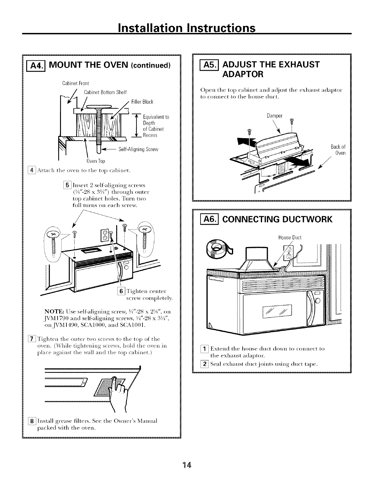
MOUNT THE OVEN (continued)
CabinetFront
CabinetBottomShelf
Filler Block
T quivalentto
Depth
of Cabinet
Recess
Self-AligningScrew
OvenTop
_]Attach tile oveml to tile top cabim/et.
[] Insert 2 sel6aligning screws
(¼"-28 x 3¼") through outer
top cabinet holes. Turn two
fifll turns on each screw.
[
[]Tighten center
screw completely.
NOTE: Use sel6aligning screw, ¼"-28 x 2:'A", on
_[g It
JVM 1790 and self:alignino, _ screws, W'-28 x. /_ ,
on JVM 1490, SCA 1f)00, and SCA 10f) 1.
[] Tightel/ the ol_te_" two sc_'ews to the top of the
ovem (\'_ hi]e tightem/im/g St Ye]ys, h(t](] the ovem/ ira/
I)]ace agai, mist. the wail amld the top cabim/et.)
S/
_]]nstall filte_3. See tile Owner Manualgi'ease
packed with tile oxen.
ADJUST THE EXHAUST
ADAPTOR
Open the top cabinet and a(!iust the exhaust adaptor
t() connect t() tile hotlse duct.
Damper
[-_ CONNECTING DUCTWORK
HouseDuct
_ Extend tile hotlse dtlct do%vn to connect to
tile exhaust adaptor.
] . ,duct tape.Seal exhaust duct ioints using
14
Installation Instructions
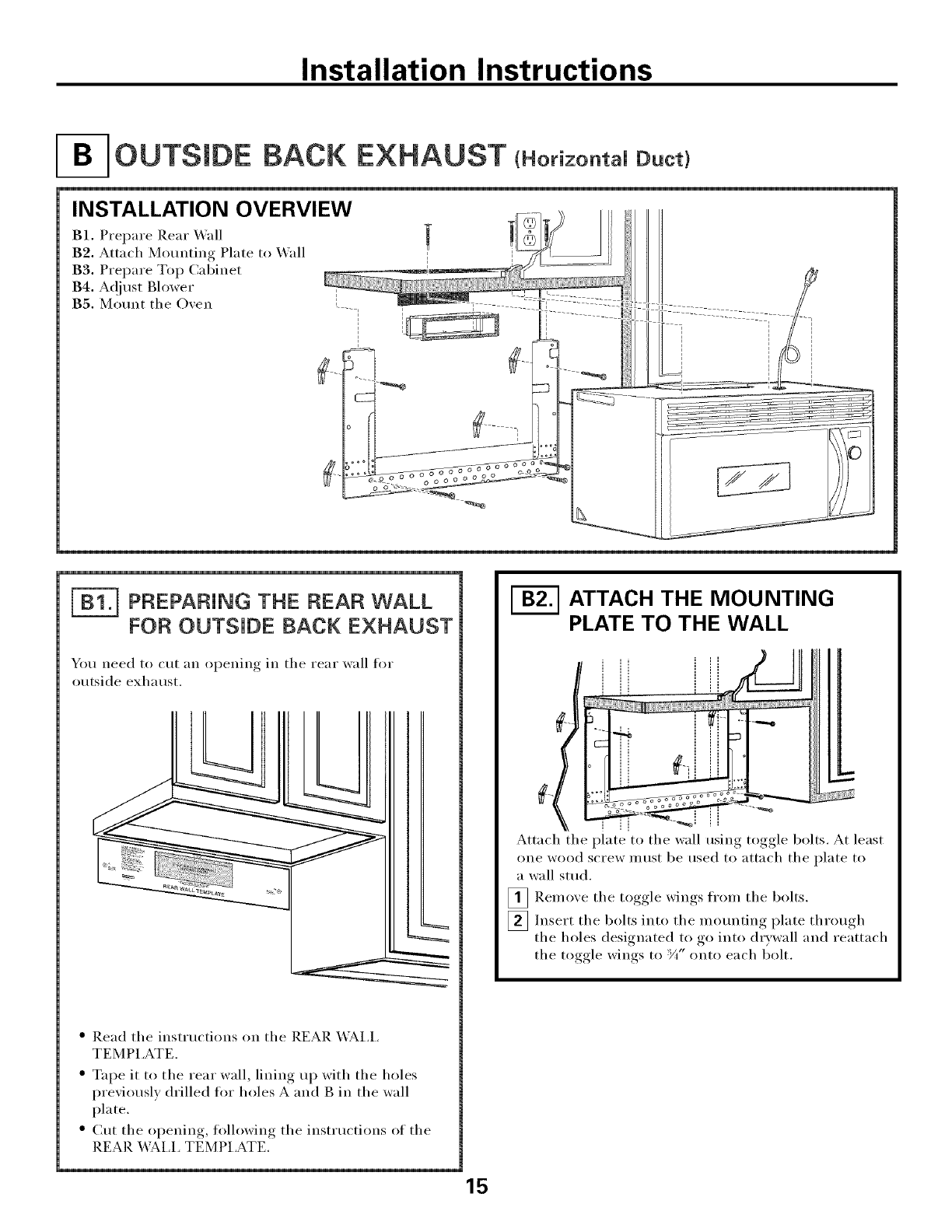
OUTSmDE BACK EXHAUST tHorkontaUD.ct}
INSTALLATION OVERVIEW
B1. Prepare P,ear _4"dl
B2. Attach Mounting Plate to X4'all
B3. Prepare Top Cabinet
B4. A_)just Blower
B5. Mom_t the Oven
F_ PREPARING THE REAR WALL
FOR OUTSIDE BACK EXHAUST
_Otl need to Ctlt [lIl l b
0 )enino in the rear wall for
outside exhaust.
" Read the instructions on the REAR X4A,I,I,
TEMPI ,ATE.
•Tape it to the rear wall, lining up with the holes
previously drilled tot holes A and g in the wall
plate.
$ ()it the opening, following the instructions of the
REAR X_;_I,I, TEMPI,ATE.
ATTACH THE MOUNTING
PLATE TO THE WALL
i
Attach the plate to the wall using toggle bolts. At least
one wood screw must be used to attach the plate to
a wall stud.
_ Remove the toggle wings ti'om the bolts.
_Insert the bolts into the motmting plate through
the holes designated to go into (hwwall and reattach
the toggle wings to '_A"onto each l_olt.
Installation Instructions
To use toggle bolts:
Mounting
Plate
Spacing for Toggles More
-,-I-----_i_ Than Wall Thickness
B
Toggle Wings
Bolt End
_ Place the mounting plate against the wall and
insert the toggle wings into the holes in the wall
to mount the plate.
NOTE: geflwe tightening toggle bolts and wood
scre_, make sure tile tabs on tile motmting plate
touch tile bottom of tile cabinet when pushed flush
against the wall and that the plate is properly
centered under tile cabinet.
CAUTION: Be careflfl to axoid pinching fingers
between the back of the molmting plate and the wall.
_ Tighten all bolts. Pull the plate awa) from the wall
to help tighten the bolts.
I-_ USE TOP CABINET TEMPLATE
FOR PREPARATION OF TOP
CABINET
You need to drill holes for tile top support screws and
a hole large enom,h for tile power cord to fit throuoh
" Read tile instructions on tile TOP CABINET
TEMPI,ATE.
" Tape it tmderneath tile top cabinet.
" Drill tile holes, following tile instructions on tile
TOP CABINET TEMPLATE.
CAUTION: _&ear safety goggles when drilling holes
in tile cabinet bottom.
ADAPTING BLOWER FOR
OUTSIDE BACK EXHAUST
_ Remoxe tile three screws that hold tile blower
plate to tile oxen. Slide blower plate from trader
its retaining, flange, . Remoxe and saxe tile screw
that holds blower motor to oxen.
Retaining _<<i_ -_
Flange _ 5_.__F..___ Blower Plate
.......... Motor
[] Carefull) pull out tile blower refit. Tile wires
will extend far enough to allow _ou to a_!just
the blower trait.
BEFORE: Fan Blade
Openings Facing Up
_ Rotate blower trait cotmterclockwise 180 °.
Before Rotation After Rotation
Oven
_ (;entlx tile wires from tile
i'ell/ove grooxes.
Reroute tile wires throu_*h grooxes on other side
of the blower trait.
Before Rerouting After Rerouting
Wires Routed Through Right Side Wires Routed Through Left Side
16
Installation Instructions
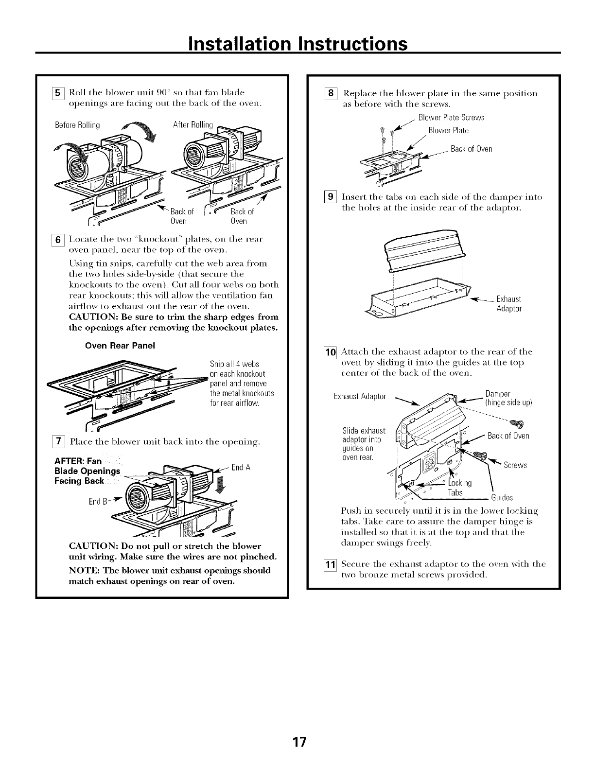
_Roll the blower unit 90 ° so that tan blade
oi_enings, are thciw,_ out the back of the o'.en.
BeforeRolling _ .
Backof l'_,_r_
Oven
Backof
Oven
[] I,ocate the two "knockout" plates, on the rear
oven panel, near the top of the oven.
Using tin snips, careflflly ctlt the web area fl'om
the two holes side-by-side (that secm'e the
knockouts to the oven). Cut all flmr webs on both
rear knockouts; this will allow the ventilation tan
airflow to exhaust out the rear of the oven.
CAUTION: Be sure to trim the sharp edges from
the openings after removing the knockout plates.
Oven Rear Panel
Snipall 4 webs
on eachknockout
panelandremove
the metal knockouts
for reara_rflow.
_ Place the blm_er trait back into the o )ening.I
AFTER: Fan
Blade Openings
Facing Back
EndA
CAUTION: Do not pull or stretch the blower
refit wiring. Make sure the wires are not pinched.
NOTE: The blower unit exhaust openhlgs should
match exhaust openhlgs on rear of oven.
] Replace the blower plate in the same position
as befi_re with the screws.
BlowerPlateScrews
1_ BlowerPlate
/
ii_i-- _1¢ Backof Oven
[] Insert the tabs each side of the intodailll) ei"
on
the holes at the inside rear of the adaptor.
Adaptor
_ Attach the exhaust adaptor to the rear of the
o'_en b) sliding it into the guides at the top
center of the back of the oxen.
Damper
ExhaustAdaptor _ _,_._,,.,..,, (hingeside up)
Slideexhaust _J/,/ _,,- Backof Oven
adaptorinto
Tabs Guides
o
Push in securely tmtil it is in the lower locking
tabs. Take care to assure the damper hinge is
installed so that it is at the top and that the
damper swings fi'eelv.
_ Secm'e the exhaust adaptor to the oven with the
two bronze metal screws proxided.
17
Installation Instructions
MOUNT THE OVEN
FOR EASIER INSTAI,I.A_TION AND PERSONAI.
SAFETY, WE RECOMMEND THAT TWO PEOPLE
INSTALL THIS OVEN.
IMPORTANT: Do not grip or use handle
during installation.
NOTE: If your (abinet is metal, use the nvlon
grommet around the power cord hole to prevent
cutting of the cord.
NOTE: We recommend using filler blocks if the
cabinet fl'ont hangs below the cabinet bottom shelf.
IMPORTANT: If filler blocks are not
used, case damage may occur from over
tightening screws.
NOTE: When m()tmting
the oven, thread power
cord through hole in
bottom of top cabinet.
Kee I) it tight throughout
Steps 1-3. Do not pinch
cord or lilt oven by
pulling cord.
[] I,itt oven, tilt it
fin'ward, and hook
slots at back bottom
edge onto two lower
tabs of m()tmting plate.
_ Rotate fi'ont (If oxen l1 I)
against (abinet bottom.
_Insert a sell=aligning screw through top center
cabinet hole. Tempora_ilv secm'e the oven by
turning the screw at least two full turns alter the
threads have engaged. (It will be completely
tightened later.) Be sure to keep power cord tight.
Be careful not to pinch the cord, especially when
mounting flush to bottom of cabinet.
CabinetFront
CabinetBottomShelf
FillerBlock
T quivalent
to Depth
of Cabinet
Recess
Self-AligningScrew
OvenTop
_Attach the oxen to the top cabinet.
_Insert 2 self-aligning screws
_I zt
(J/('-98 x. ¼ ) through outer
top cabinet holes. Turn two
till turns on each screw.
U
_ Tighten center
screw completely.
NOTE: Use self-ali.,*ning, screw, ¼"-28 x _2_:' ", on
JVM 1790 and sell=aligning screws, ¼"-28 x 3 V(',
on .[VM 1490, SCA 1f)00, and SCA 1f)f}1.
[] Tighten the outer two screws to the top of the
oxen. (X._bile tightenin(* screws, hold the oxen
in place against the wall and the top cabinet.)
_ Install grease filters. See the Owner's Manual
packed with the oxen.
18
Installation Instructions
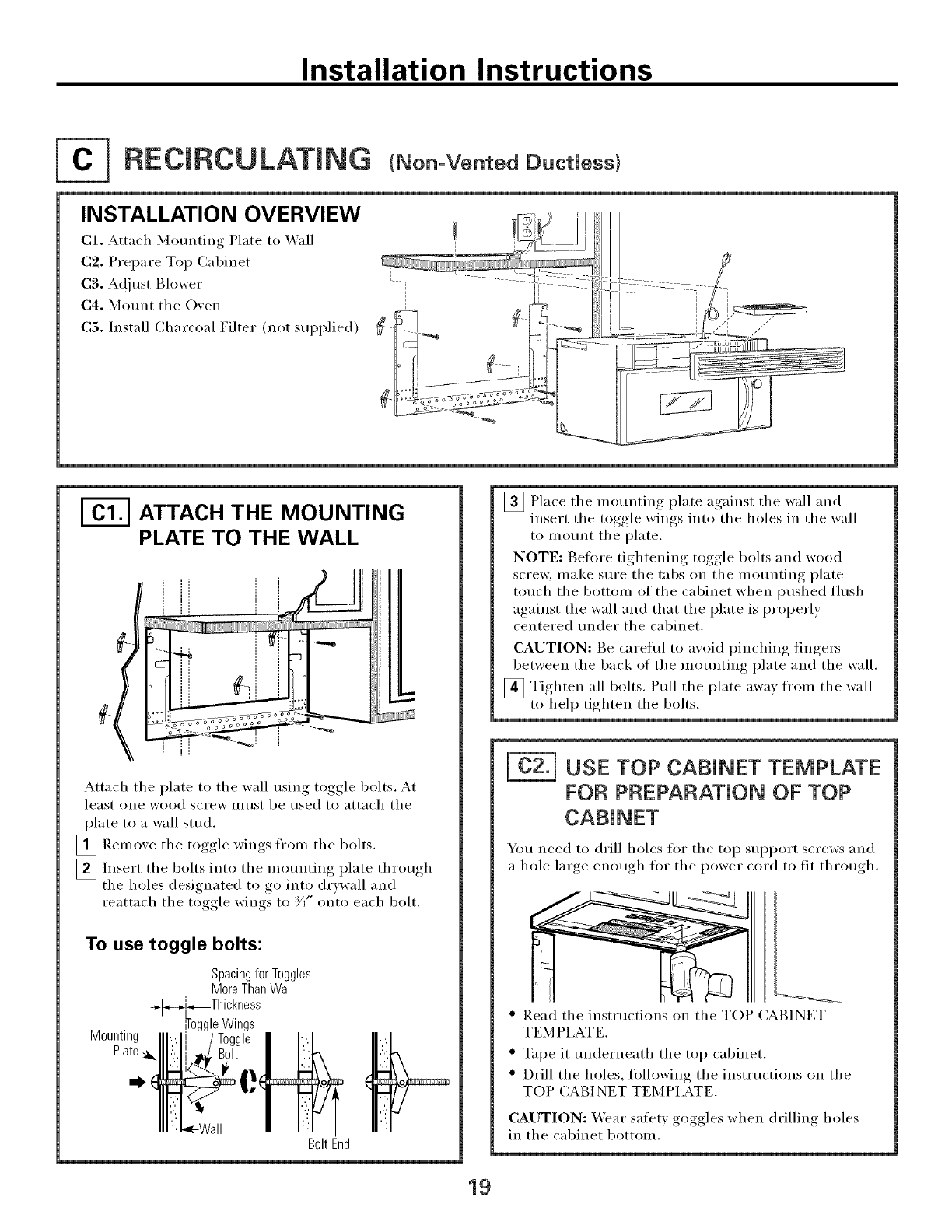
RECIRCULATmNG tNon-VentedDuctUess)
INSTALLATION OVERVIEW
C1, Attach M(mnting Plate to _'all
C2. Prepare Top Cabinet
C3. Adjust Blower
C4. Mount the Oven
C5. Install Charcoal Filter (not supplied)
I-_ ATTACH THE MOUNTING
PLATE TO THE WALL
Attach the plate to the wall using toggle bolts. At
least one wood screw Inust be used to attach the
plate to a wall sttld.
[]Remove the toggle wings fl'om the bolts.
_ Insert the bolts into the mounting plate through
the holes designated to go into drywall and
reattach the toggle wings to :Y{' onto each bolt.
To use toggle bolts:
Spacingfor Toggles
MoreThanWall
+[_-.[.--Th ckness
Wings
Mounting
Plate_
if,
BoltEnd
_ Place the mounting plate against the wall and
insert the toggle wings into the holes in the wall
to inount the plate.
NOTE: Befl)re tightening toggle bolts and wood
scre_, make sure the tabs on the mounting plate
touch the bottom of the cabinet when pushed flush
against the wall and that the plate is properly
centered trader the cabinet.
CAUTION: Be careflfl to axoid I)inchiw*_ fingers,
between the back of the motmting plate and the wall.
_ Tighten all bolts. Pull the plate awax from the wall
to help tighten the bolts.
USE TOP CAP4NET TEMPLATE
FOR PREPARATION OF TOP
You need to drill holes for the top support screws and
a hole large enouoh for the power cord to fit throuoh
" Read the instructions on the TOP CABINET
TEM PI,ATE.
" Tape it tmderneath the top cabinet.
" Drill the holes, tollowing the instructions on the
TOP CABINET TEMPLATE.
CAUTION: _ear satety goggles when drilling holes
in the cabinet bottom.
19
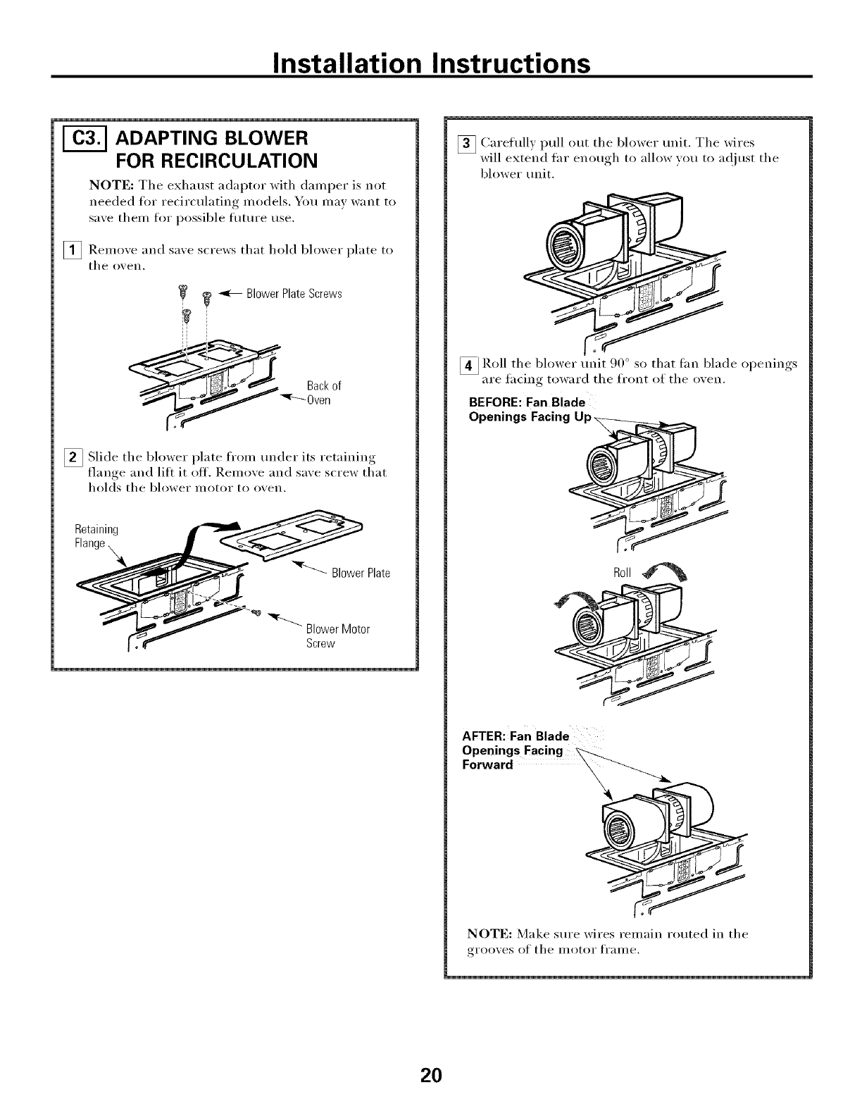
Installation Instructions
ADAPTING BLOWER
FOR RECIRCULATION
NOTE: The exhaust adaptor with damper is not
needed fin" recirculating models. You may want to
save them for possible flmu'e use.
[] Remoxe and saxe screws that hold blower plate to
tile O_ eIl,
_ _ Blower Plate Screws
[]Slide tile blower from trader itsplate i'etaining
flange, and lifi it off, Remoxe and saxe screw that
holds tile blower IllOtOI" to o'_en,
Retaining __
Flange _'__v__"__ BI )wer Plate
3_ Carefully pull out tile blower trait. Tile wires
will extend flu" enough to allow xou to adiust the
blower trait.
•( o - I &'
_4 Roll tile blower rant .)0 so that fan blade o )enim*s
-- are fhcing toward the front of the oxen.
BEFORE: Fan Blade
Openings Facing Up_
AFTER: Fan Blade
Openings Facing
NOTE: Make sure wires remain routed in tile
gi'oo_,es of the I/lOtof fI'aIlle,
2O
Installation Instructions
ADAPTING BLOWER FOR
RECIRCULATION (continued)
[] Place the blower m/it back ira/to the o )eni m/g.
CAUTION: Do not pull or stretch the hlower _t
wiring. Make sure tile wires are not pinched°
[] Sectu'e blower unit to o_en with the screw
removed in Step 2. Insert the screw in bottom
right screw hole on the back of the o_en.
_ Replace blower plate with the screws removed in
Step l.
_ Blower Plate Screws
Back of Oven
" _ Blower Motor
Screw
MOUNT THE OVEN
FOR EASIER ]NSTAI,IATION AND PERSONAl,
SAFETY, WE RECOMMEND THAT TWO PEOPLE
INSTALL THIS OVEN,
IMPORTANT: Do not grip or use handle
during installation.
NOTE: If your cabinet is metal, use the nvhm
grommet around the power cord hole to prevent
cutting of the cord.
NOTE: We recommend using filler blocks if the
cabinet fl'ont hangs below the cabinet bottom shelf.
IMPORTANT: If filler blocks are not used,
case damage may occur from over tightening
screws.
NOTE: When mounting
the oven, thread power
cord through hole in
bottom of top cabinet,
Keep it tight throughout
Steps F-3. D() not pinch
cord or lili o',en bx
mllino cord.
_ i,if't oven, tilt it
flwward, and hook
shits at back bottom
edge onto two lower
tabs of mounting plate.
_ Rotate front of oven
up against cabinet
bottoul,
_lnsert a sell=aligning screw through top center
cabinet hole, Temporarily secure the oven by
turning the screw at least two full turns atier the
threads have engaged, (It will be completely
tightened later,) Be sure to keep power cord tight,
Be careful not to pinch the cord, especially when
mounting flush to bottom of cabinet,
CabinetFront
CabinetBottomShelf
FillerBlock
Equivalentto Depth
f CabinetRecess
Self-AligningScrew
Oven Top
_Attach the oxen to the top cabinet.
21
Installation Instructions
MOUNT THE OVEN
(continued)
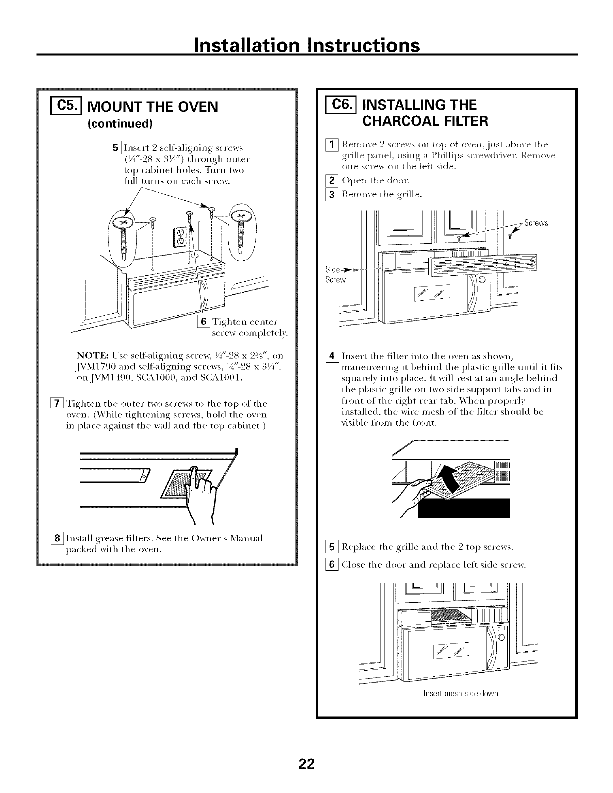
_ Insert 9 self-aligning screws
_l tt_
(V('-28 x. ¼ )through outer
top cabinet holes. Turn two
fllll turns on each screw.
_ Tighten center
screw completely.
NOTE: Use self-aligning screw, Vt"-28 x 2%", on
IVM 1790 and self=aligning screws, Vt"-28 x. w ,
on .[VM 1490, SCA 1000, and SCA 1001.
[] Tighten the outer two screws to the top of the
o;en. (_hile tightenino screws, hold the o;en
in place against the wall and the top cabinet.)
_ Install grease filters. See the Owner's Manual
packed with the oxen.
INSTALLING THE
CHARCOAL FILTER
_Remove 9 top of ove]i,just above the
_screws o]_
g]'i]] e pam_el, usi m__, ,_ [ ]] d ] ] d[_Lscrewdriver. Rein ove
o]_e sc]'ew om_[he ]ef[ side.
_ ()pe]_ the door.
_ Remove the g]i]]e.
Side--_
Screw
J
J
•Screws
_ Insert the filter into the oven as shown,
maneuvering it behind the plastic grille until it fits
squarely into place. It will rest at an angle behind
the plastic grille on two side SUl)port tabs and in
fl'ont of the right rear tab. When proi)erly
installed, the wire mesh of the filter should be
visible fl'om the fl'ont.
_ Replace the grille and the 2 top screws.
[] Close the door and replace left side screw.
Insert mesh-side down
22
Installation Instructions
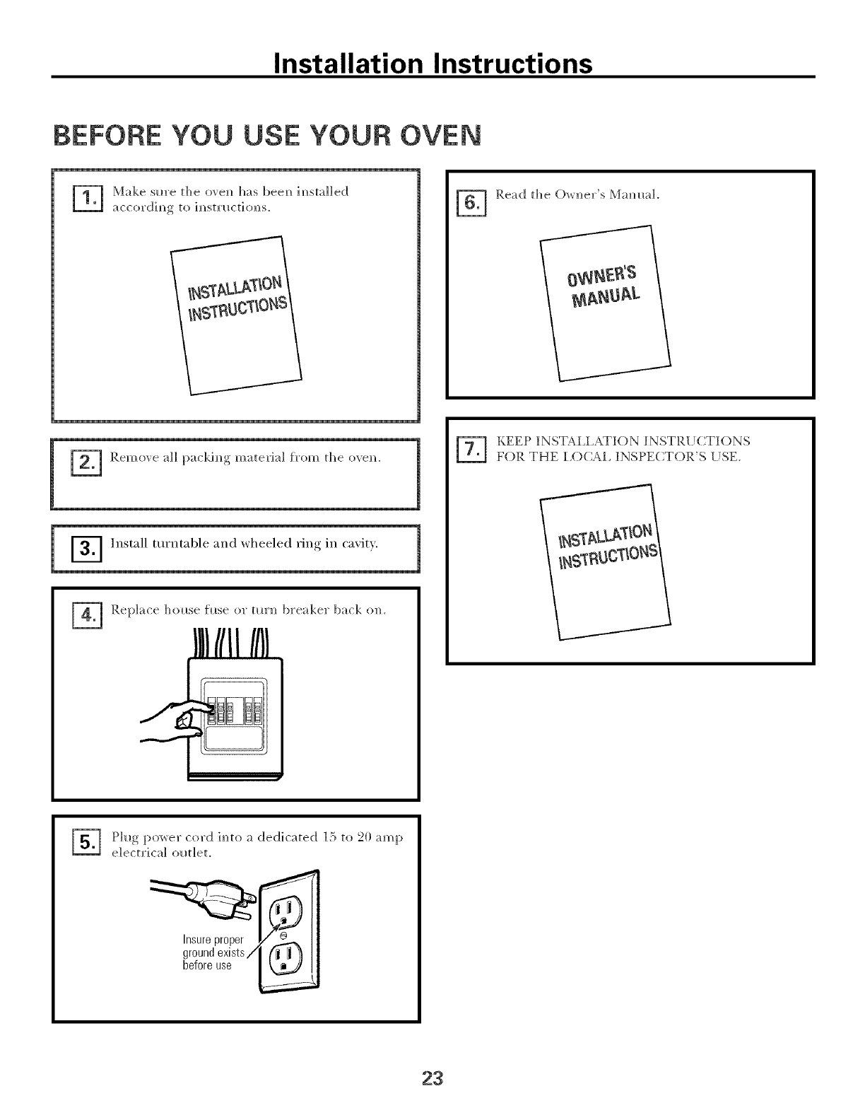
BEFORE YOU USE YOUR OVEN
_7_ Make sm'e the ovem_ has beeN_ im_stalled
acco]'dim_ to im_st]'l_ctio]_s.
/
/%
_ Remove all packim_g mate_'ial from tl_e m'e_.
7_ Replace house rinse o]" tm']_ bx'eake]" back o]_.
IllIIIIHII
Read the Ow]_e]"s Mammal.
KEEP INST¢[.[.ATION INSTR[!(}TIONS
FOR THE 1,(7)(_I, INSPECTOR'S [!SE.
r_ h_g powei" co]x] im_to a dedicated ]3 to 20 amp
electx'ical outlet.
Insure proper
ground exists/ _
before use
23

Printed in Korea
24
In r "
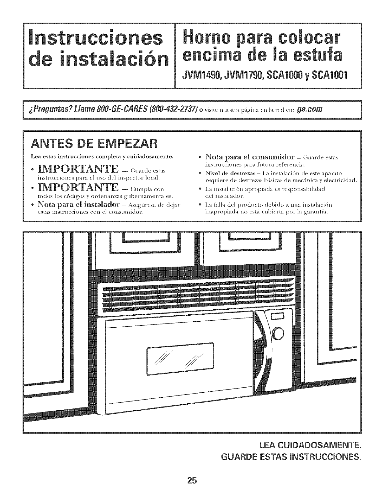
m m f
0car
JVM1490,JVM1790,SCA1000ySCA1001
ANTES DE EMPEZAR
Lea estas mstrucciones completa y cnidadosa_enteo
i_strL_cci(mes para e] I_so (]e] im_spector h)ca].
• IMPORTANTE -_:_.._pl..,_
to(los los c6(]i_os _ or(]emmzas g_l)er]_ameN_tales.
Nora para el inst_ador = _se_0rese de (]eiar
estas im_st_l_cdom_es com_ e] col_Slm_]dor.
* Nora para el consumidor _(;l_ar(]e estas
im_stmcckmes para flmm_ re{erel_cia.
o Nivel de destrezas - i,a im_sta]aci6m_ de este apax_to
reql_iere de destrezas b_sicas de mecSm_ica y e]ectricidad.
o I,a im_sta]aci61_ apropia(_!a es resp(msabi]i(]a(_!
(]e] i_sta]a(]or.
@I,a fhl]a de] pro(]_a:to (]ebido am_a i_sta]aci61_
LEA CU_DADOSAMENTE.
GUA_DE ESTAS _NST_UCC_ONES.
25
mnstrucciones
hformaci6n generM
Instruceiones de seguridad importantes ................ 27
Requisitos et6ctrieos .............................................. 27
Campana de escape .......................................... 28, 29
Da/!os - Env_o /Instalacidn .................................. 30
Partes h]cluidas ...................................................... 30
Herramientas que necesitar_ .................................. 31
Espacio de montaje ................................................ 31
Guia de instMaci6n paso pot paso
Cdmo colocar el plato de montaje .................... 32-34
(i;6mo remover el phm_ de momm_ie ............ 32
Cdmo emwmm'_r madera s6]ida
era/ ]a pared .................................................. 32
Cdmo determim_r h_ h)c_Iizacid]/
de ]as ph_c_s de h_ pared ............................ 33
()Smo alim/ear la ph_c_ de h_ pared .............. 34
Tipos de instalaeidn .......................................... 3546
_ Escape slq)erior .......................
exteYioY. 36-38
C6mo adherir la [:)h_c_ de
mom/t_je _ h_ pared .............................. 36
Preparacid]/ de] gabim/ete siq:)erior . ..... 37
C6mo im/specciom_r si h_ opemci6]/
del regldador de tim es apropiada ...... 37
C6m o mo]/ tar el h orm/o .................. 37, 38
Cdmo _jl_star el adaptador de esc;q:)e ..38
C6mo cm/ectar h_ red de co]/(h_ctos °°-38
_ Escape posterior extemo ...................... 39_-2
C6mo preparar la pared posterior
para el escape posterior exterior ........ 39
C6mo adherir e] plato de
mom/t_je _ ]a pared ........................ 39, 40
Cdmo preparar el _gabim/ete .sl_[)erior..... 40
C6mo adaptar e] caIeihctor [:)ar_
el escape exterh)r posterior . ........... 40, 41
(:(.7/o mol/ta r el h o].m/o........................ 42
de
Recirc_dacidl/ ........................................ 43-46
C6mo adherir e] plato de
mo_/t_je a ]_ pared .............................. 43
C6mo preparer e] g_bi_/ete s_q:)erior...,43
Cdmo adaptar e] ca]efhctor
para ]a recirc_d_cid]/ ...................... 44, 45
C6m o mo]/ tar e] h or_/o .................. 45, 46
()3too ]_/sta]m" e] fi]tro de carb(m]]Ia....45
A_]tes de eomenzar a usar su homo ...................... 47
26
mnstrucciones de
mNSTRUCCmONESDE SEGURIDAD mMPORTANTES
Este i)ro(]{_cto requiere m] tomacorrie]]te el_ctrico
de tres patas com_ecta(]o a tierra. E] il_sta]ador debe
]]evar a cabo m]a im_speccid]_ de co]_timd(]ad a tierra
eN_]a/a]a el_ctrica m_tes de comem_zar la im_sta]acidm_
[)ara asegurar, que ]a ca.]a tomacorrie]_te est;_.{ o]_ectada
a tierra de mam_era apropiada. Si m) lo est;i, o si el
tomacorrieme m_ cump]e coil los reqldsitos
e]_ctricos i_]dicados (ba.]o ]a seccid]_ REQ[JISITOS
EI]_CTR]COS), se deber;i recmTir a m_ t_c_ico
calificado para corregir cualquier deficie_]cia.
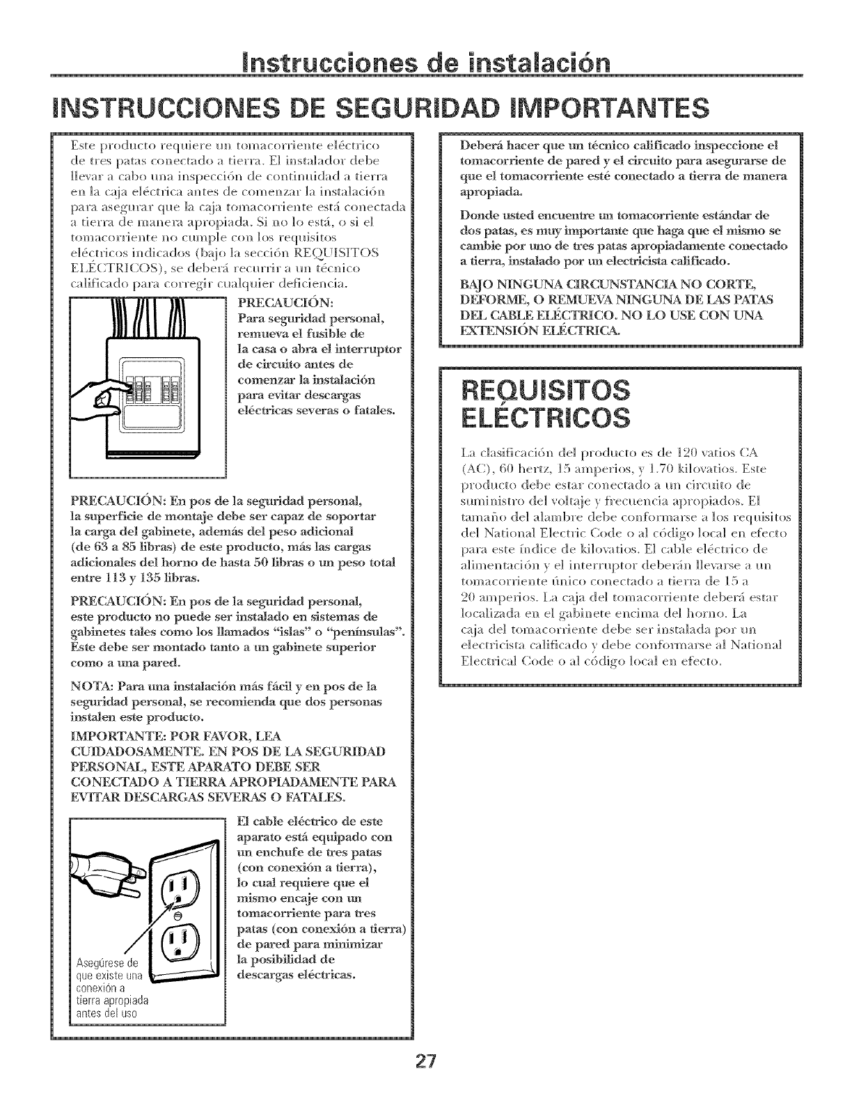
PRECAUCBSN:
Para seguridad personal,
remneva e! fusible de
la easa o abra el interruptor
de eireuito ames de
comenzar la instalad6n
para evitar descargas
e]detricas severas o fatales.
p
PRECAUCI(IN: En pos de ]a seguridad personal,
]a superfide de montaje debe ser eapaz de soportar
]a earga de] gab_nete, ademfis de] peso adieional
(de 63 a 85 libras) de este prodneto, mrs ]as eargas
adieionales de1 horno de basra 50 libras o tm peso total
entre 113 y 135 tibras.
PRECAUCI{SN: En pos de la seguridad personal,
este prodneto no puede ser iJ_stalado en sistemas de
gabinetes tales eomo los llaaa_ados "isla_s" o "penlnsulas'.
Este debe ser montado tanto a m! gal)inete superior
eomo a mla pared.
NOTA: Para mqa instalaei6n mrs ffiell yen pos de la
seguridad personal, se reeomienda qne dos personas
instalen este prodnem.
IMPOR_I_TE: POR FAVOR, LEA
CUIDADOSAMENTE. EN POS DE LA SEGURIDAD
PERSONAL, ESTE APARATO DEBE SER
CONECTADO A TIERRA APROPIADAMENTE PARA
EVITAR DESCARGAS SEVERAS O FATALES.
til I/I
•i/I
E1 cable el6etrico de este
apaarato estfi equipado con
m_ enehufe de tres paros
(con eonexidn a fierra),
1o enal requiere que el
mismo eneaje con m_
tomacorriente para tres
paras (con conexidn a tierra)
de pared pasta m_fizar
]a posibilidad de
descargas el&etricas.
AsegOresede
que existe una
conexiOn a
tierra apropiada
antes del uso
Deberfi haeer que mq t6ertieo califieado inspeceione el
tomaeorriente de pared y el ekeuJto para asegurarse de
qne el tomacorriente est6 eoneetado a tierra de manera
apropiada.
Donde nsted encnentre tm tomaeorriente estfindar de
dos paras, es m W importante que haga qne el mismo se
eambie por mqo de tres patas apropiadamente eoneetado
a fierra, i_stalado por tm eleeMeista ea_fieado.
BAJO NINGUNA CIRCUNSTANCIA NO CORTE,
DI_'ORME, O P&2MUEVA NINGUNA DE LNS PATAS
DI_3L(7ABLE EI_C_[NICO. NO LO USE CON UNA
_N_I_]NSI()N FI_;CTRI(_
I,a c]asificacidl_ del prod_,cto es de 120 ratios CA
(AC), 611 hertz, ]5 amperMs, y ].70 ki]ovatios. Este
producto debe estar co]_ectado a m_ circ_ito de
sm_i_fistro de] vo]taje y f_'ec_e_cia apropiados. E]
tamai_o de] a]ambre debe c(mformarse a los reqllisitos
del Natiomd Electric Code o al cddigo local e_ efbcto
para este f_dice de kilovafios. E1 cable e]_ctrico de
a]ime]_taci6]] v el ]_terr_q]tor (]ebe_:i_ ]]evarse a _m
[oi]/acorrie]/_e i_/Jco co_/ec[ado a[Jerra de ]5 a
21) ampeIlos, l,a ca.ia de] tomacorrie_te deber;i estar
]oca]iza(]a el/ e] gabi_]ete e]/cJma (]el hor]_o, l,a
c;_ja de] tomacorrJe]_te debe set i_]sta]ad;_ pot m]
e]ectricista ca]ificado vdebe co]_tbrmarse a] Nation,a]
E]ectrica] Code o a] c6digo ]oca] e_ efl_cto.
27
mnsttucciones de instaJacidn
CAMPANA DE ESCAPE
NOTA: Lea ]as siguientes dos pfiginas solm_lente si plar_ea venNar e] escape hacia el exterior.
Si por e] contrario p]m]ea rec_-cular el ake de vue]ta hacia e] saldn, continfie en ]a pfigina 30.
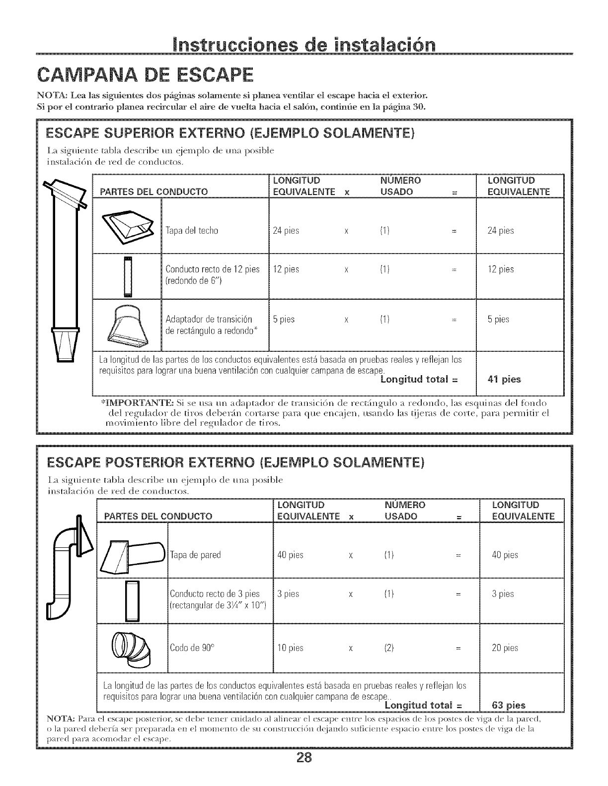
ESCAPE SUPERIOR E×TERNO (EJEMPLO SOLAMENTE}
I,a sig_ie_]te mbla describe m_ eiem p]o de m_a posible
im_stal_cidm_de red de co_ductos.
PARTESDEL CONDUCTO
Tapadeltecho
Conductorectode 12pies
(redondode 6H)
AdaptadordetransiciOn
de rect_nguloa redondo*
LONGITUD NOMERO
EQUWALENTE xUSADO
24 pies (1)
12pies (1)
5pies (1)
LaIongitudde las partesdelos conductosequivalentesest_basadaen pruebasrealesy reflejanlos
requisitospara!ograrunabuenaventilaci6nconcualquiercampanade escape.
Longitud total =
LONGITUD
EQUIVALENTE
24 pies
12pies
5pies
41 pies
*IMPORTANTE: Si se I_sa m_ adaptador de mmsicid_ de rect_im_gu]o a redom_do, ]as esqldm_s del [o_do
(]el reg_lador de tiros del)er_im_ cortarse para ql_.e e]_c_:ie]_, i_.sm_do ]as t!ieras de corte, [::_ara permitir e]
mo','imieN_to libre del reg_lador de tiros.
ESCAPE POSTERIOR EXTERNO (EJEMPLO SOLAMENTE)
La sig_dem_te tabla describe m] eiemplo de m_a posible
i_stalacid]_ de red de c(md_ctos.
[
LONGITUD NOMERO LONG[TUB
PARTESDEL CONDUCTO EQUIVALENTE x USADO = EQUIVALENTE
_ Tapade pared 40pies x (1) 40pies
Conductorectode3 pies 3 pies x (1) 3 pies
(rectangularde 3W' x 10")
(_ Codode 90° 10pies x (2) 20pies
La!ongitudde las parlesde losconductosequivalentesest_basadaenpruebasrealesy reflejan los
requisitosparaIograrunabuenaventilaci6nconcualquiercampanade escape..
Longitud total = 63 pies
NOTA: P_a uI escape posterior sc dcbc te_]cr (:/_id;_do _I _[ine_[" u] csc _pu untrc los usp _cios de los postes dc _ig_ dc h_ p_u:cd,
o 1/par(d deber_ _ set _)repa[" _da el/e/!]!o!]/e!]1o de s// co!/s[['ticcil)!/ d_,i _1/(]o S[ll'i(;iel/_e es}_ _(;io el_tle los }_ostes (]e _ig/ de ]a
}lAte(/ _)arA ACO]]_od _F (_] escAi}e.
28
mnstrucciones de instaJacidn
NOTA: Si rated m_ecesita h_stalar co_(h*ctos, te_g_
pem_(tiente que la lo_gimd tot;t] de1 com_(h_cto recm_g_lar
de 3K/' x ]i0" oel con(;h_cto re(]xmdo de 6" de di_h_etro
no debe sobrepasar 140 pies equivalentes.
l,a ventih_ci6_ extema re(p_iere m_ CONDI/CTO DE
(iAMPANA DE ES(iAPE. I,ea lo sig/*ie_te cl_idadosm_e_te.
NOTA: Es importame (p_e ]a ve_ti]acidm_ sea i_sta]ada
Ilsal/do ]a nmt m_s dh'ecta v col/k_ reel/or camidad de co(los
posible. Esto asegm:_ la vemilad6m_ del escape y :_y_d_ a
prevel/h" b]oq{lec, s. Tambi6n, eerd6mse de que el regulador
de tiro pende libremente y nada Moquea los eonduetoso
Conexiones de escape:
l,a cm_pm_a de escape h_ sido diseSada pare el_c_{iar c<m
m_ co_(h_cto rectm_gu]ar de 3¼" x ]0" est;h_dar.
Si im coi?(hlcto redo_?do es _?ecesalJo, se debe/lsar im
adaptador de mmsici&_ de rectang_h_r a redtmdo.
No use m'_ eonduem menor de 6" de di_imetroo
Longitud maxima de_ conducto:
Pars ]og_r m_ movimie_m_ s_tisfi_ctorio de] _ire, 1_
hmgimd total del co_(h_cto recta_gular de 3_//' x ](1"
o el co_(;h_cto redondo de 6" de di_h_etro no debe
sobrepasar 140 pies equivalenteso
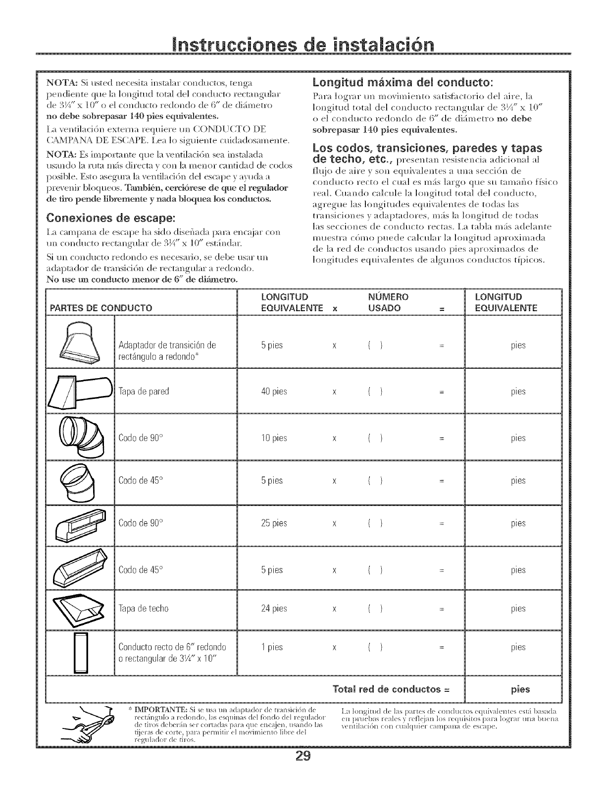
Los codos, transiciones, paredes y tapas
de techo, etc., presel_ta,_ resiste,_cia _dichmM al
fi_io de sire _ so_ e(p_ivale_tes a m_a secci6_ de
co_(h_cto recto e] c_] es m_.s ]argo q_e s_ tam_ff_o ffsico
real. (h_a_do c;dc_le h_ lol_gimd total del co_(h_cto,
agreg_e ]as ]o_gimdes eq_h'a]e_tes de todas ]as
mmsicio_es y _daptadores, m_is h_ hmgimd de todas
]as seccio_es de co_d_cto rectas, l,a tab]a re;is ade]a_te
m_estra c6mo puede calc_lar h_ lo_gimd aproximada
de ]a red de co_(;h_ctos _sa_do pies aproximados de
lol_gimdes eq_iva]e_tes de algmms col_(h_ctos tipicos.
LONGITUD NOMERO LONGITUD
PARTE$ DE CONDUCTO EOUIVALENTE x USADO = EOUIVALENTE
Adaptador de transici_n de 5 pies x ( } = pies
rect_ngulo a redondo_
Taps de pared 40 pies x ( ) = pies
(_)_ Codode 90° 10 pies x ( } = pies
Codode 45° 5 pies x ( ) = pies
Codode 90° 25 pies x ( } = pies
J Codode45 ° 5pies x ( } = pies
Taps detecho 24 pies x ( ) = pies
Conducto recto de 6" redondo 1 pies x ( ) = pies
o rectangular de 3V_"x 10"
Total red de conductos = pies
,_IMPOR_ANTE: Si s_usa m_adapmdor d_:mmsic%n d_:
29
Jnstrucciones de instalaci6n
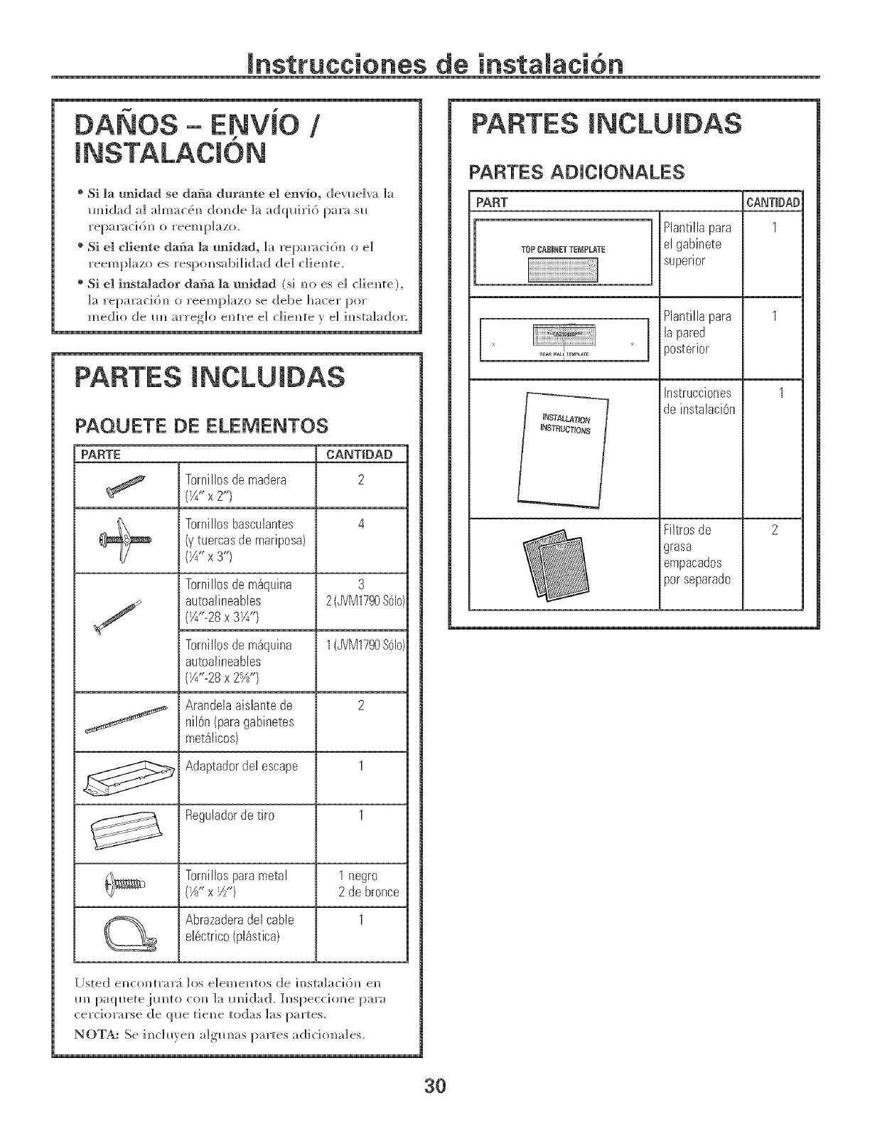
-ENViO I
® Si la u_dad se dafia durante el en%o, devueIv_ Ia
mfidad aI aIm_c_m_d(mde Ia adquiri6 parasu
reparac]d]] o reemp]azo.
® Si el cliente da_a la t_idad, ]_ repa_cidm o e]
reemplazo es respo_sabilidad dd diem_te.
®Si el instalador dafia la mlidad (si m_ es el clie_te),
la repar_ci6m_ oreemplazo se debe h_cer pot
medio de m_ '_rre_,Jo e_tre el clien_te _ el im_stalador.
PARTES INCLUJDAS
PAQUETE DE ELEMENTOS
PARTE CANTtDAD
Torrfillosdemadera 2
(Y4"x 2")
_\ Tornillosbasculantes 4
_/_ (ytuercasde mariposa)
(_A"x Y')
Tornillosdem_quina
autoatineables
(¼<28x 3Y4")
Tornillosdem_quina
autoatineables
(¼<28x 2%")
3
2(JVM1790S61o)
1(JVM1790SOlo)
Arandetaaislantede 2
nil6n(paragabinetes
met_licos)
Adaptadordel escape 1
Reguladordetiro 1
Tornillosparametal 1 negro
(Yd'x Y/') 2 debronce
Abrazaderadelcable I
el_ctrico(pl_stica)
[Jsted em_c(mtrar;_ los e]eme_tos de im_sta]aci(3_ e_
m_ pa(puetejm_to co_ la m_id;_ck h_speccio_e i)_ra
cerciorarse de que tie_e todas ]as partes.
NOTA: Se i_cluye_ algm_as p_rtes adicim_ales.
PARTES INCLUIDAS
PARTES ADICIONALES
PART
[TOPCABINET TEMPLATE
tN,S3"_LL_TIOI_
INSTFIUCTIONS
Plantillapara
el gabinete
superior
Plantillapara
lapared
_osterior
Instrucciones
de instalaci6n
Filtrosde
grasa
empacados
pot separado
CANTIDAD
3O
Jnstrucciones de
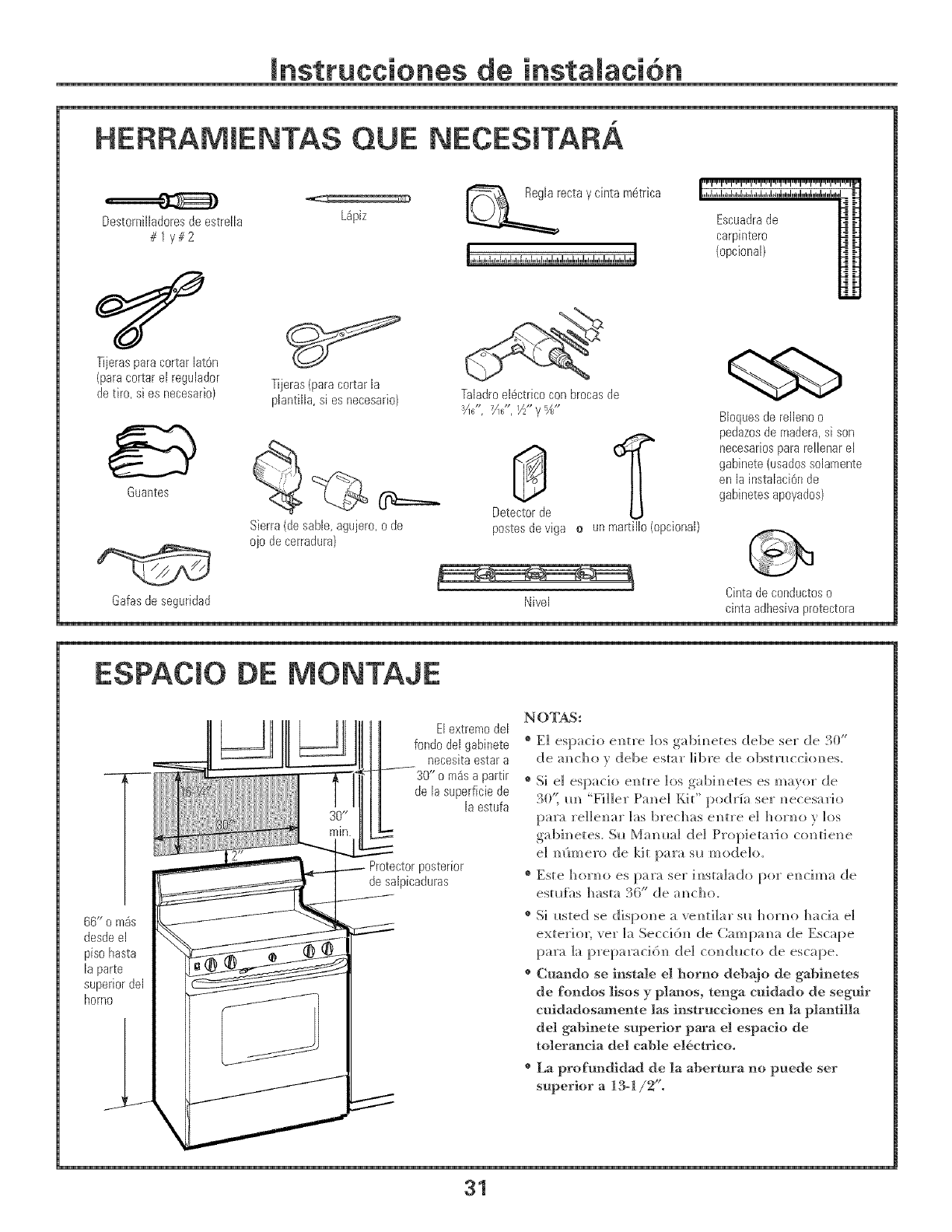
HERRAMJENTAS QUE NECESJTARA
Dest0rnilladoresde estrella
#1y#2
Tijeras para c0rtar latOn
(para c0rtar el reguiad0r
de tir0, si es necesari0)
Guantes
L@iz
Tijeras (para c0rtar Ja
piantiila, si es necesari0)
Sierra (de sane, agujer0, o de
oj0 de cerradura)
ecta y cinta m6trica
Taiadro el@ctricocon brocas de
3 ** 7 **
Gafasdeseguridad
Escuadra de
carpinter0
(0pci0nal)
BJ0quesde reJJeno0
pedazos de madera, si son
_ necesarios para rellenar eJ
gabinete (usados solamente
en la instalaci6rl de
gabinetes apoyados)
Detector de
postes de viga oun martillo (opcional)
k J Cinta de conductos 0
NiveJ cinta adhesiva protectora
ESPACJO DE MONTAJE
66" o m_s |1
desde el |
piso hasta |
Japarte |
Elextremodel
fondodel gabinete
necesitaestara
30" o m4sa partir
de Jasuperficiede
Jaestufa
Protectorposterior
desalpicaduras
NOTAS:
®E1 espario entre los g_]binetes de]be ser de 30"
de ancho y debe estar ]]bre de o]bstxl_cdones.
®Si e] espacio entre los gabinetes es mayor de
BO't m_ "Filler Panel Kit" I)odrfa ser necesario
para reHenar ]as bred]as entre el horno vlos
gabinetes. Six Mamma] de] Propietario cont]ene
el mimero de 1dr par;_ sl_ modelo.
®Este horno es para ser ]nsmlado por endma de
esm{hs hasm 36" de ancho.
®Si Ixsted se dis[)one a venti]ar six horno ]_acia e]
exteriox; vex" ]a Seccidn de Campana de Escape
para 1;/ preparaddn de] conducto de escape.
®Cuando se instale el homo debajo de gabinetes
de fo_ldos ]isos y plmms, tenga cuidado de seguir
cuidadosmnente Ias instrucciones en la plantilla
del gabinete superior para el espacio de
tolerancia del cable e16ctrico.
®La profmldidad de Ia abertura no puede ser
superior a 13-1/2".
31
mnstrucciones de
C(}MO COLOCAR EL PLATO DE MONTAJE
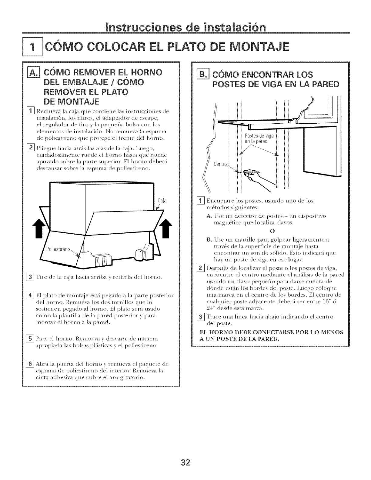
COMO REMOVER EL HORNO
DEL EMBALAJE 1COMO
REMOVER EL PLATO
DE MONTAJE
[] P,eml_eva la ca]a ql_e contiene ]as iasm_cciones de
im_stalaci6n, los filtros, el adaptador de escape,
el reg_lador de tiro y la pequeha bolsa con los
elemem_tos de instalaci6n. No reml_eva la espuma
de po]iestix'em_ ql_e px'otege e] fl'e_te de] hoxl_o.
[] P]iegue hacia at__s ]as alas de ]a c;}ja_ I,l_ego,
cl_idadosamente rl_ede e] homo ]]asta que ql_ede
apo_do sobre ]a parte superior. El homo deber5
descam]sar sot)re ]a espm]]a de po]iestireN]o.
[] Ti_'e de ]a c_{]a hacia arriba _ reH_'e]a de] homo.
Caja
_E] plato de mcmt_!je est:_ pegado a ]a pa_'te posted'ion"
de] homo. Reml_ew_ los dos torni]los (p_e ]o
sostienen pegado a] ]_orno. E] plato set5 i*sado
como ]a p]am_ti]]a de ]a pared posterior y para
montar el homo a la pared.
_ Pa]'e e] ]]o]m>. ]_{em_oeva _ desca]'te de ma_e]'a
a[)_'opiada ]as bo]sas I)h_sticas y e] po]iesti_'eno.
_ _kl)ra ]a p_erta de] hondo vrem_teva el paq_tete de
espm_ a de po]i esti re_ o de] i _ te_'i or. Rein _eva ]a
ci_ta adhesiva que cub_'e e] aro giratorio.
32
mnstrucciones de
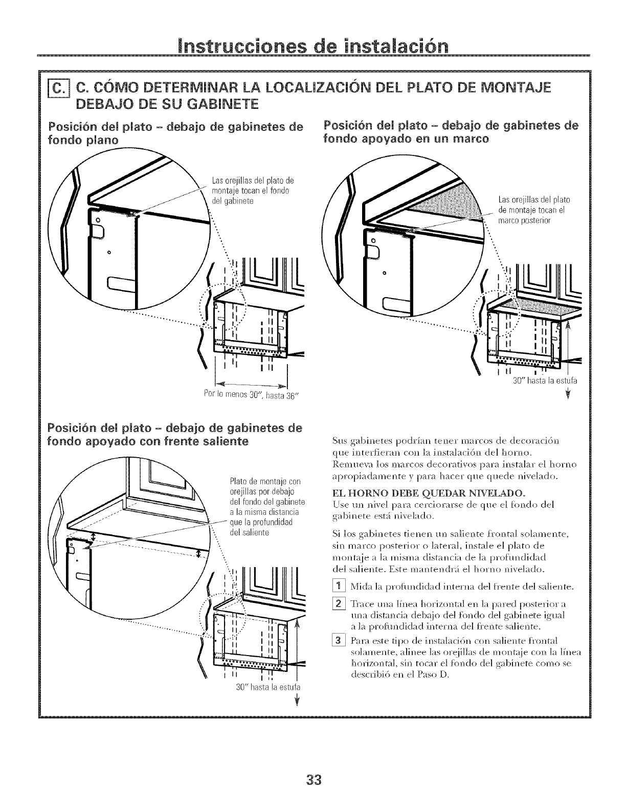
C. C6MO DETERMJNAR LA LOCAUZACR)N DEL PLATO DE MONTAJE
DEBAJO DE SU GABJNETE
Position del pUato - deba]o de gabinetes de
fondo pUano
Posicibn deU plato -deba]o de gabinetes de
fondo apoyado en un marco
Las orejillas del plato de
montaje tocan el fondo
deJgabinete Las orejiiias del plato
de montaje tocan el
marco posterior
L
I II a_,_
PerIo menos30", hasta36"
II
30" hasta la estufa
Posici6n deU plato - debajo de gabinetes de
fondo apoyado con frente saUiente
Platode montajecon
orejillas pordebajo
del rondodel gabinete
a la mismadistancia
profundidad
del salbote
II
30" hasta ia estufa
Sl*s gabim_etes podr£am_ teller marcos de decoraci6]_
que im_teHieram_ co_ la im_smla_i6m_ del horm_o.
P,em_leva los marcos decorativos para im_stalar el horm)
apropiadamem_ te y para hacer qI*e qI*ede m_ive]ado.
EL HORNO DEBE QUEDAR NIVELADO.
[°se m_ m_]ve]para cerc]orarse de ql*e e] fimdo de]
gabim_ete est', m_ivelado.
Si ]os gabim_etes tieN_em_m_ sa]ie]_te f_xmta] so]ame]_te,
s]m_marco posteric, r o lateral, im_sta]e e] plato de
m<mtaie a ]a m]sma distam_c]a de ]a prohmdidad
de] sa]]em_te. Este mam_te]_(h5 e] hor]_o _]ve]ado.
[]
[]
[]
Mida k_ pro[m_didad i_ter]_a (]el fre_te (]el sa]ie]_te.
Trace mm ]f_ea horizo]_ta] e]_ ]a pared posterior a
m]a distancia deb;!jo de] {hi, do de] g_]bh_ete igua]
a ]a prol_m_didad i_ter]_a de] _'e_te sa]ie_te.
Para este tipo de ]_sta]aci6]_ co]_ sa]ie]]te {_'o]_ta]
so]ame_ite, a]h_ee ]as or@Has de moi_ta{ie co]_ ]a ]f_ea
horizoi/ta], si_/ tocar e] {hi/do de] gabi_ete como se
describi6 e_ e] Paso D.
33
mnstrucciones de
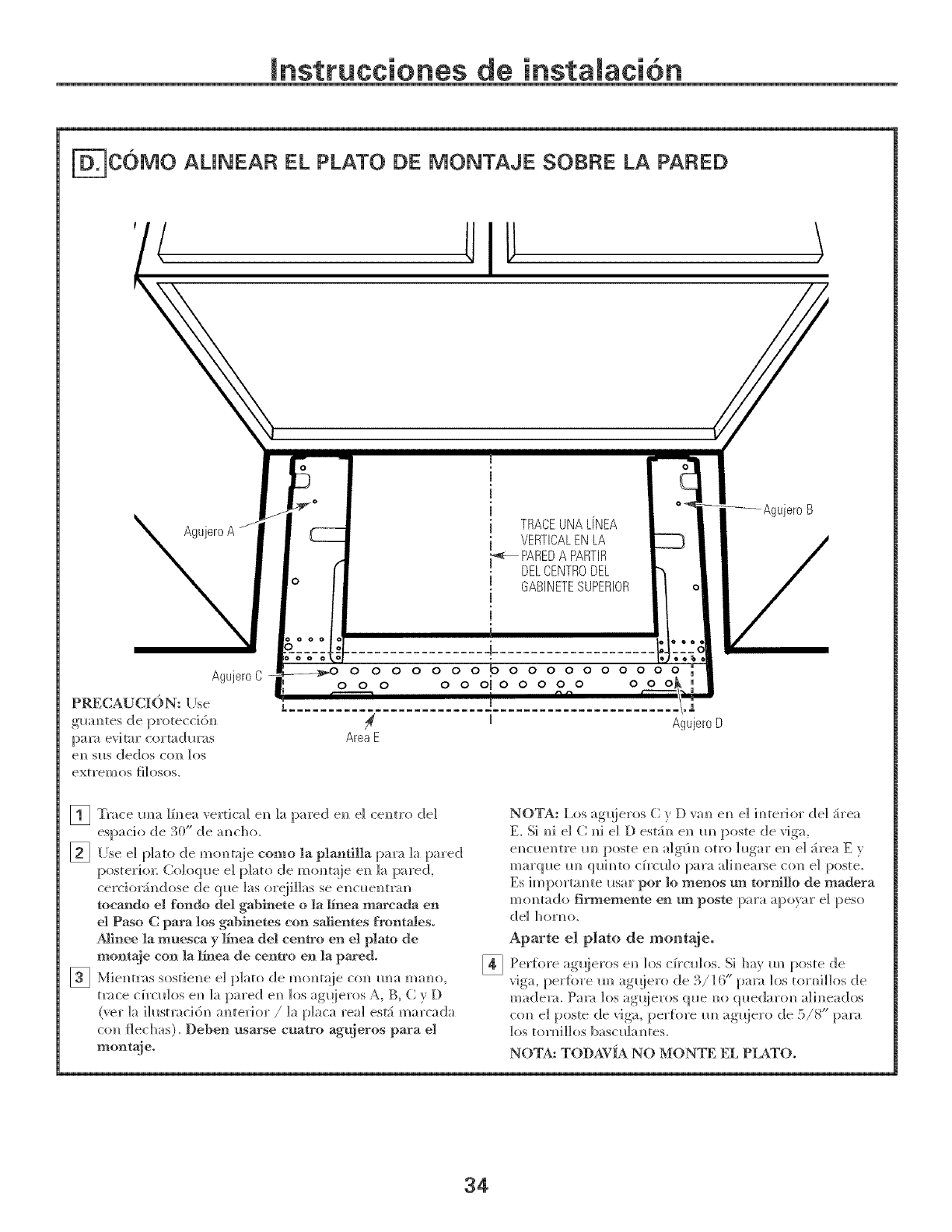
F C6MO AUNEAR EL PLATO DE MONTAJE SOBRE LA PARED
TRACEUNAL[NEA
VERTICALENLA
_PARED A PARTIR
DELCENTRODEL
GABINETESUPERIOR
_Agujer0 B
Agujer0C
glmm_tes de proteccidm_
[:>a_;_evitar cortadl_ras
em_S{IS dedos col_ los
extrem os _ilosos.
0000000000 0 0000 00
0 0 0 0 00iO 0 0 0 0 0 0
m
AreaE
|
Agujer0D
_ Trace m_a l[m_ea vertical e_ la pared e_ el cem_tro de1
[] llse el plato de mo_taje como la plantilla para Ia pared
posterior; Co]oql_e e] p]ato de mom_t_!ie e_ ]a pared,
cercio_indose de que ]as or@Has se el_cl_elm_m
toeando el rondo del gabmete o la _nea marcada en
el Paso C para los gabSaetes con sal_entes front,ties.
Al_nee la muesca y E'_ea det centro en el plato de
montaje con la 15-1eade centro en la pm°ed°
[] Miemm'as sostie_e el p]ato de m<mmje com_ mm mambo,
t_s_ce c_ro_los e_ la pared e_ los agqieros A, B, (} y D
(vet la ih_stmcidn a_terior /la placa real esti marcada
co_ flechas). Deben usarse cuatro ag_eros para el
nlont_.
[]
NOTA: l,os agqieros C v D va_ e_ el h_te_Jor de1 :irea
E. Si _i el C_1 el D est_i_ en m_ poste de riga,
e_c_e_tre m_ poste e_ a]gfi_ otto ]_gar el_ el _irea E v
marque m_ qui_to cfrcu]o para ali_earse con e] poste.
Es importm_ te usar por lo menos un tornJ]]o de madera
mo_tado firmemente entm poste para apo)_r el peso
(]el hondo.
Aparte el plato de montaje°
Per{i)re ag_!ieros e_ los c_ro_los. Si hay m_ poste de
riga, per{ore m_ ag_iero de 3/16" pare ]os U)H_i]]os de
madem. Pal_ los ag!!ieros que _?o qlledaro_/a]h?eados
co_ el poste de riga, per{i_re m_ ag_jero de 5/8" para
los tor_illos bascu]a_tes.
NOTA: TODA¥_A NO MONTE EL PLATO.
34
mnsttucciones de
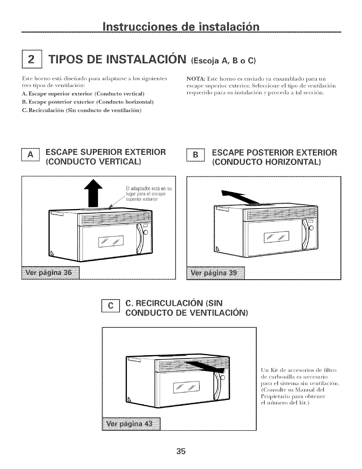
TmPOSDE mNSTALACi6N (EscojaA,Bo C}
Este hoH_o est:i disef_do para adaptarse a los sigl_]em_tes
tres tipos de vem_til_cidm_:
A° Escape superior exterior (Condueto vertica!)
B° Escape posterior exterior (Condueto horizontal)
C. Recireulacidn (Sin condueto de ventilacidn)
NOTA: Este hoH_o es em]','iado )a em_samblado p_ra m_
escape slq:_erior exterior. Selecci(me el tipo de ",'e]_til_cid]_
reql_erido para su im_stal_cid]_ } proceda a tal seccidm
ESCAPE SUPERIOR E×TERIOR
(CONDUCTO VERTICAL)
ESCAPE POSTERIOR E×TERIOR
(CONDUCTO HORIZONTAL}
t El adaptador est4 en su
.lugar para el escape
_/superior exterior
C. RECIRCULACION (SIN
CONDUCTO DE VENTILACION)
I[]_ Kit de accesorios de filtro
de carbo_illa es _ecesario
par_ el sistem_ si_ ve_tilacidm
(Co]_s_]te s_ Mamm] de]
el mimero de] kit.)
35
mnstrucciones de
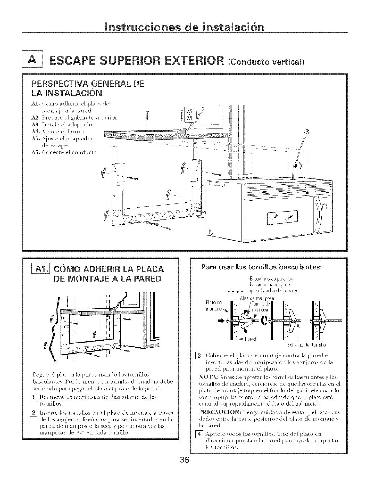
ESCAPE SUPERmOR EXTERmOR (conauctovmicai}
PERSPECTJVA GENERAL DE
LA INSTALACION
A1. Como adherir el plato de
mo_taie _ Ia pared
A2. Prepare el g_bh_ete sl_perior
A3. h_stale e] ad%_tador
A4° Mo_te el homo
ASo _iuste el adaptador
de esc_pe [.....
A6o Co_ecte el com_dl_cto
COMO ADHERJR LA PLACA
DE MONTAJE A LA PARED
Pegue e] plato a ]a pared usm_do los ton_iHos
b:_scl_hmtes. Pot ]o mem)s m_ tor]_iHo de madera debe
set i_sado [_a_:_ [,_egar e] [)]ato a] poste de ]a p_red.
[1 Reml_ex'_ ]_s mariposas de] bascl_]_mte de los
ton_iIIos.
[2 h_serte los toH_illos en el plato de mo_taie a tra_'_s
de los ag_!ieros diseSados p_m_ set im_sertados e_ la
[>ared de mare I)°ster[a....... seca v,t)egue, otra vez ]_s
_?)i_l'i[)os_s de ,_H el/ cada ton)ill(/.
Para usar 10s t0miil0s bascuiantes:
Espaciadores para los
basculantes mayores
_,-I.,-_j-,,_que el ancho de la pared
'_las de mariposa
Plato de
montaje
36
Pared
Extrem0del tornillo
[] Coloq_e el plato de mo_taie co_tra la pared e
]_serte l_s alas de mariposa e_ los ag_ieros de 1_
pared pa:':_ mop, tar el p]ato.
NOTA: A_tes de apretar los tor_illos b_sc_lm_tes y los
tor_illos de madera, cercidrese de (p_e l_s or@llas e_ el
plato de m(mt_ie toq_e_] el {i_do de1 gabi_ete c_a_do
so_ emp_iadas co_tra la pared y de q_e el plato este_
ce_t_.do apropi_dame_te deb_!io de1 gab]_ete.
PRECAUCION: Tel_ga c_ddado de evitar peHizcar sl*s
dedos e_tre la [x_rte postexJor (]el plato de mo_t:_ie y
_ Apriete todos los toH_illos. Tire de1 pl_m_ el?
direccid_ opuesta a ]a pared para ayudar a apretar
los toH_illos.
Jnstrucciones de
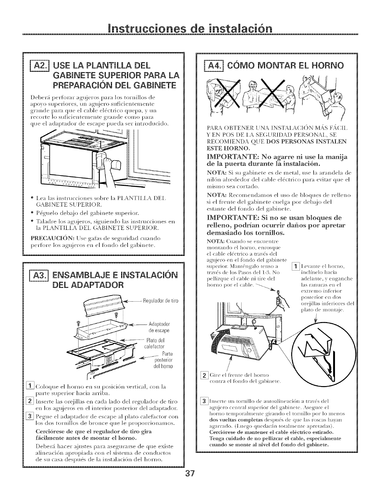
USE LA PLANTJLLA OEL
GABJNETE SUPERJOFI PARA LA
PREPARACK}N DEL GANNETE
Deber_i perfomr ag_ieros para h_s torniHos de
a poyo sl_[)eri ores, i_m__g/!iero sll[i ci e_ tern e_ te
gr_mde par_ ql_e el c_ble e]eSctlJco ql_epa, y m_
recorte 1o sllfidel/temel/te gral?de como pare
ql_e el ad!aptad!or de escape p/_ed!a set im_trodh_cido.
® I,ea las im_stmccio_es sobre la PIANTII,I,A DEI,
GABINETE Si IPERIOR.
® P_gl_e]o deb_jo de] gabim_ete slq_erior.
® T_dadre los ag!_jeros, sig_ieN_do h_s instmcciones e_
la P1ANTILLA DE1, GABINETE SilPERIOR.
PRECAUCI()N: Use ga{i_s de segmJdad time, do
perfore los ag_jeros e_ e] flmdo de] gabi_ete.
| ENSAB/IBLAJE E INSTALACION
DEL ADAPTADOF{
ReguJadorde tire
Adaptad0r
deescape
[] Co]oq_e e] hor_m e_ s!* posid6_ vertical, co_ ]a
parte s_.perior h_ci_ arribm
[] h_serte ]as or@Has e_ cada ]ado de] reg_]ador de tiro
e_ los ag_jeros e_ e] i_terior posterior de] adaptador.
[] Pegue e] adaptador de escape a] plato c_de{i_ctor con
los dos toH_i]]os de bro_ce (p_e ]e
Cercidrese de que el regulador de firo gira
fficilmente antes de montar el horno°
Deber:i hacer _]ustes par_ _segtm_rse d!e que existe
aIi_ead61_ aproph_d_ co_ el s]stema de co_(_hlctos
de s_ c_sa des[:mets de ]a i_stah_ci6_ de] hormz
| COMO IONTAR EL HORNO
PARA OBTENER UNA INSTAIACI(')N M._S F._CII,
YEN POS DE I,A SE(_UPdlIAD PERSONAI., SE
RECOM:IENDA Qi_E DOS PERSONAS INSTALEN
ESTE HORNO.
IMPORTANTE: No agarre ni use la manija
de la puerta durante la instalacidm
NOTA: S] s_ gabi_ete es de metal, _se ]a _mmde]a de
_]]6n _drededor de] c_b]e e]e}ctrico par_ evitar q_e e]
mismo sea cortado.
NOTA: e] _*so de b]oq_*es d!e re]]elm
si e] f_'e_te d!e] gabh_ete c_e]ga pot deb_ijo de]
esta_]te de] flmdo de] gabi_ete.
IMPORTANTE: Si no se usan bloques de
reUeno, podr_an ocurrir dafios por apretar
demasiado los tornillos.
_[ns_r/_ m! tomillo d_ amo di_cacidn a/raxds deI
ag_]cro <:_mr d s_q)erior deI gabincI_. ,\s_ gm'e el
holl_l} /c]/!})l}£ ih!/elH(} _it'_l/do el [ol!}i[Io })l)]" II) III(}//OS
dos vuell.as completas d( sp_ds de q_e las ros<: _s harm
ag_t'_do. (1,u<go ql*ed u'in mmlmem_ apreladas).
Cereldrese de mantener el cable el6d.rlco esfirado°
Ter_ga euldado de r_o pelllzcar el cable, especlalmer_te
cuar_do se mor_te al Nvel del for_do del gabmeteo
37
Instrucciones de
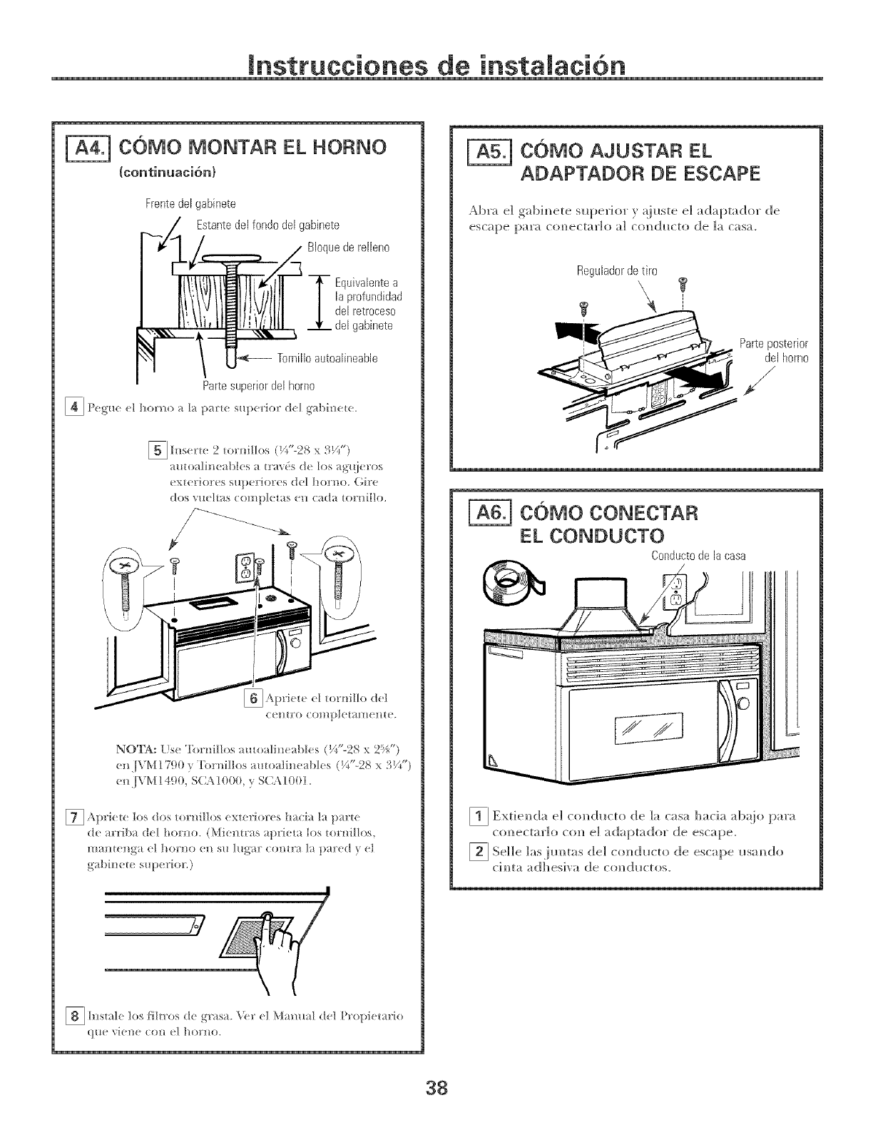
COMO MONTAR EL HORNO
{continuaci6n}
Frentedel gabinete
Estantedel fondodel gabinete
Bloquederelleno
2quivalentea
la profundidad
del retroceso
del gabinete
Tornillo autoalineable
Parte superior del homo
5h>erw.... 2 _ornftIos (_ -28 x _ V_ )
al_toaline;_bl_ s a tt'£,('s d( los ag"._i( ros
_ XteI'iol'es S/l})el"iol'es del hol'_to. (}il'e
dos v/_(Itas cI)l/IpIel;{s (// (:;_(];{ _o1!/iI!o.
C_. !/[ t'O CO!/!} )1( [}lI'_/( ll_ ( ,
NOTA: Lse 'I)>t'nillos amoalin( abk s (V_ -2,_ x 2Y_ )
_.]\M/790 y '['ornillos amoati_ d_k s (Y/'-2S x 31A")
_ JVM ! 490, S(]X 1000, } S(]\ 1001.
7_ Aprk t( los dos tornillos exteriores [l _cia I_ ]p _rte
de arriba deI homo. (Miemr _s ap_ieta los {ornillos,
l//aBteH_t el 1/OI"1!O eB SH l_l_a£ ColHla la pared el
gabinete superior;)
[] [_smle los t]lwos d< \'{r el Mam*al d<lgrasa.
(/[t( '_(fl/(f (Oll _.l ho!'llO.
COMO AJUSTAR EL
ADAPTADOR DE ESCAPE
Abra el gabi_ete superior } a i_ste el adaptador de
escape para co_/ec[arlo a] c(mduc[o de ]a casa.
Reguiador de tiro
COMO CONECTAR
EL CONDUCTO
Conducto de la casa
[1 Extie_da e] co_ducto de ]a casa hacia para
co_ectar]o co_ e] adaptador de escape.
Selle lasjlmtas del c(mdl_cto de escape itsa_/do
c]_?ta ad]?esi'G_ de col?dHctos.
38
mnsttucciones de
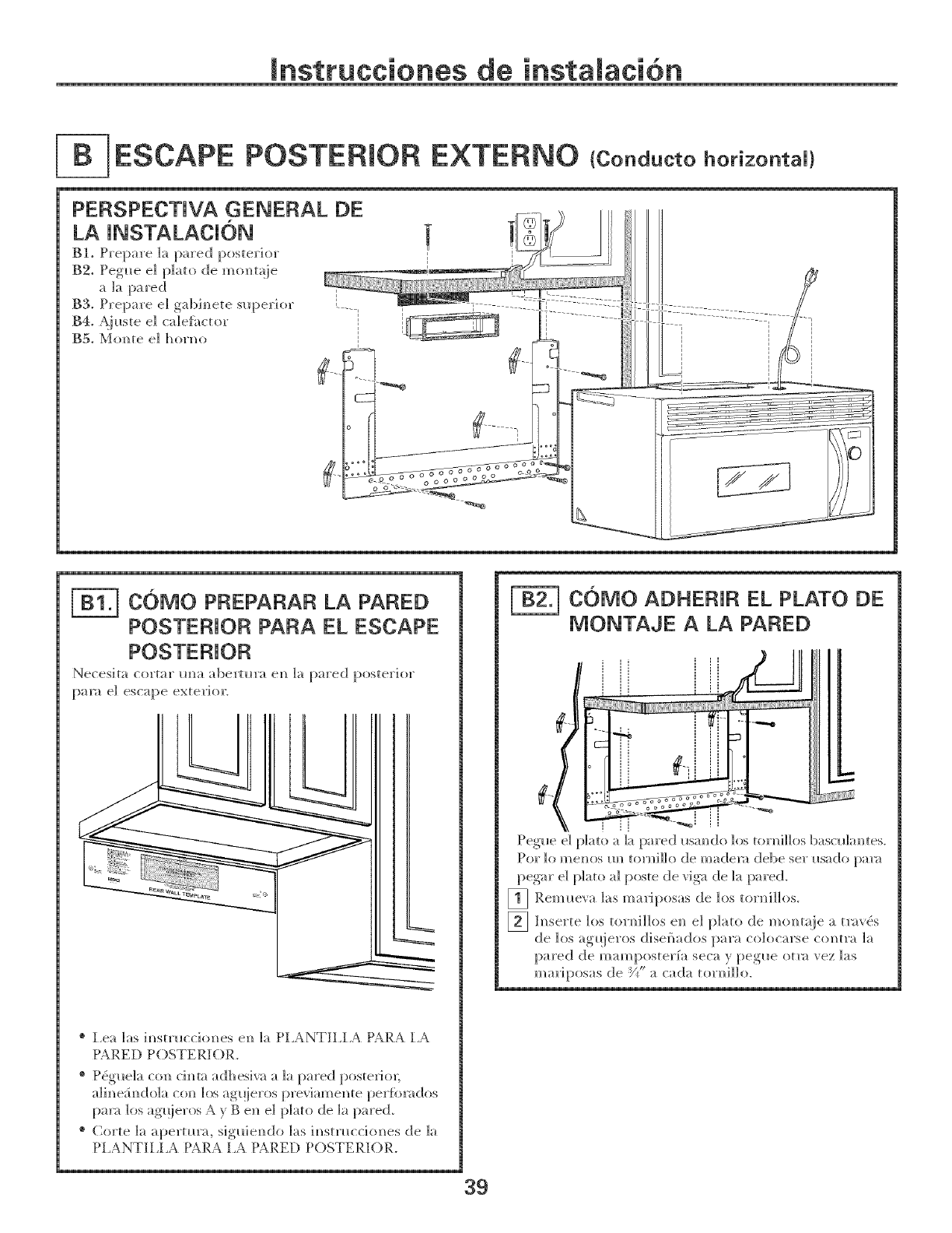
[- ESCAPE POSTERmOR EXTERNO tCond.ctohorkontaU!
PERSPECTJVA GENERAL DE
LA JNSTALACJ6N
Blo Prep_re la pred posterior
B2. Pegl_e e] p]_to de mo_m_je
a la pared
B3o Prepare e] gabinete slq)erior
B4, Aj!_ste e] calee_ctor
BSo Mom_te e] horl_o
COMO PFIEPAFIAF{ LA PARED
POSTERIOR PARA EL ESCAPE
Necesita col'tar ima abermra e]_ ]a pared posterior
pare e] escape exterior.
® Lea ]as imlstrL_cci(mes ell la PL_NTH,L¢ PARA I,A
P¢RED POSTERIOR.
® Pe}g_e]a co]_ ch_ta adhesiw_ a ]a pared posterior;
a]im_e;_m_do]aco_] los ag!!ieros previm_el_te per%mdos
[xm_ los ag_!ieros A v B e]_ e] plato de ]a pared.
® Corte ]_ apermra, sig_iem_(]!o ]as im_stmccitmes de ]a
PI,ANTH,[,A PARA I,A PARED POSTERIOR.
COMO ADHERJFI EL PLATO DE
MONTAJE A LA PARED
39
mnsttucciones de
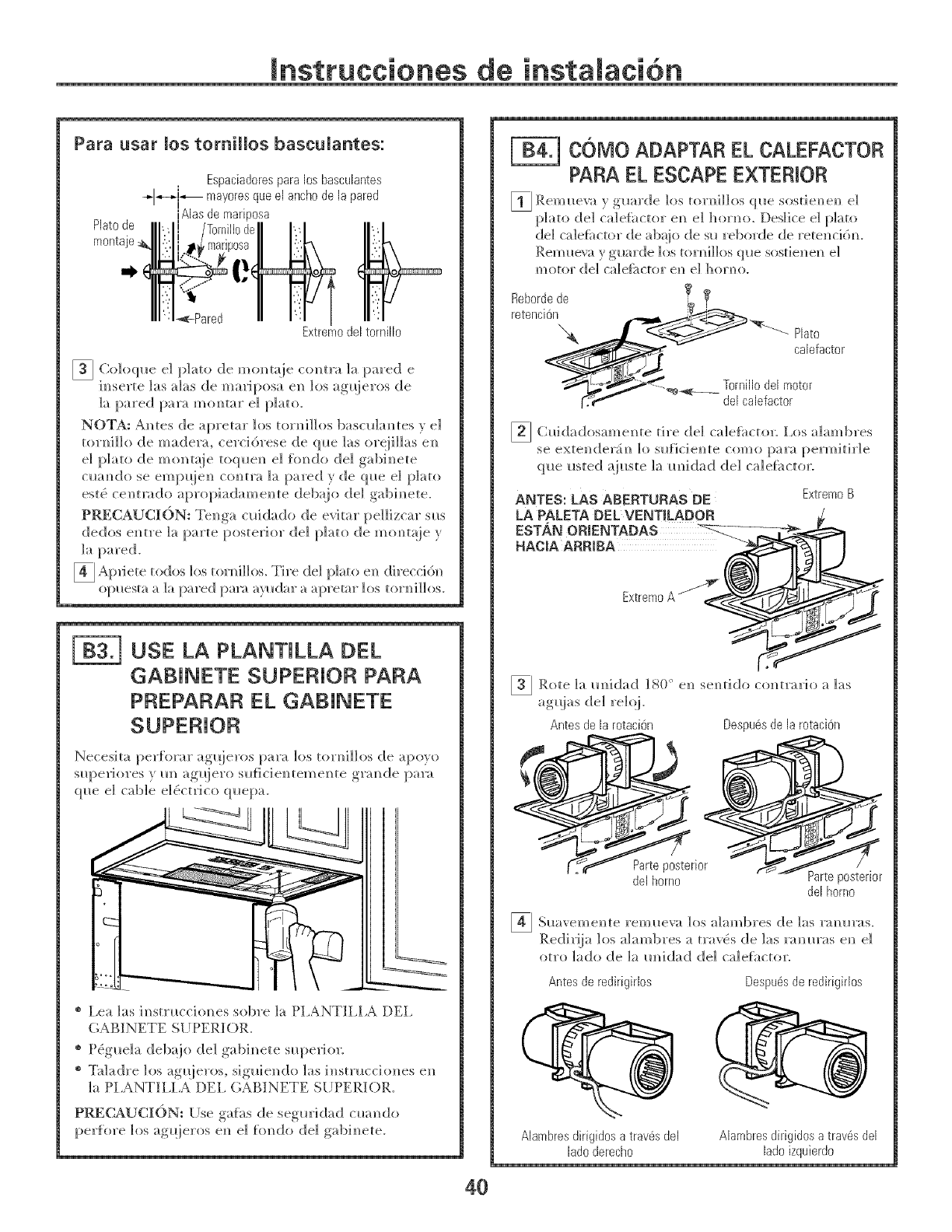
Para usar los tomillos bascuUantes:
Plato de
monta
Espaciadores para los bascuhntes
-.-I--d--- mayores que eJ ancho de Japared
IAlas de mariposa
Extremo del tornillo
[] Co]oql_e el p]ato de momm_je co_m'a ]a pared e
h_serte ]as _das de mariposa e]_ ]os agqieros de
]a pared par:/mommtr e] plato.
NOTA: AN_tes de apretar los tor]_i]]os ]bascl_]am_tes v d
torm_i]]o de mader_/, cerddrese de ql_e ]as or@Has eN_
e] plato de montaie to(p_em_ e] fimdo de] gabim_ete
cl_am_do se empqieN_ com_tra ]a pared y de (p_e e] jp]ato
este} ce]_tmdo apropi_/dame]_te deb_{io de] gabim_ete.
PRECAUCI6N: Tel_ga cuidado de evitar pellizcar sl_s
dedos em_tre ]_/parte posterior de] p]_/to de mom_t_!ie y
]_/ pared.
4_ Ap_iete tod!os los tortoni]los. Tire d!el plato em] d!ireccid]]
o[:mesta a ]a pared [:>m_t ayl_dar a apretar los tor_]]]os.
[-_ USE LA PLANTILLA [3EL
GABINETE SUPERIOR PARA
PREPARAR EL GABINETE
Necesita per[orar agqieros ]:>:rot los tor,_iHos d!e apo}!_,
superiores _. m_ ag/!iero sldicie_teme_te ,grm_de I>a]'a
q ue el cable el 6ctri co q uepa.
® I,ea ]as i,_smlccio,_es sobre ]_/ PI/kNTH,I,A [)El,
(;_B_NETE S[ JPERIOR.
®Pe}gue]_/delx_io de] gabi,_ete superior.
® T_d_/(l!re los agqieros, sig/liendo ]as insmlcciones e,_
]a PI./_NTH,I,_ DEI. (;_BINETE S[JPERIOR.
PRECAUCI(')N: [Jse gaf_/s de seg/_rklad cual/do
perfore ]os agqieros e,_ e] fm_do de] g;_bi,_ete.
['_ COMO ADAPTAR EL CALEFACTOR
PARA EL ESCAPE EXTERIOR
_ Rem_eva y g_/rde ]os tor_i]los q_e sostie_e_ e]
p]_m_ del c_defi/ctor e,_ e] horror. Des]ice e] p]_/to
de] c_deihctor de ab@) de s_ reborde de rete]/ddm
Rem_e_t y g/_arde los tor,_i]]os (p_e sostie]_e]_ e]
motor de] ca]efi/ctor el/ e] ]/o11/o.
Reborde de _ IF
delcalefactor
[] Clddadosame]lte tire de] ca]e[i/ctor, lx_s a]ambres
se exte_/der_i_ 1o su[icie,_te como [:/ara permitir]e
que usted _{iuste _a m]Jdad de] c_de{;_ctor.
ANTES: LAS ABERTURAS DE ExtremoB
LA PALETA DEL VENTiLADOR
ESTAN OR_ENTADAS _:-_-
HAOIA ARRIBA
Extreme A _ _.
[]Rote 1;t m_idad 1SO° se,_tidocmm'ario ]_/s
el)
agu'as,,! de1 re]@
Antes de la rotaciOn Despubs de la rotaciOn
_rior
del horno Parte posterior
del homo
] S!_aveme]_te los ;dm_l)res de ]as
rem_eva 1"_/_) 10]KtS.
Redir!ia los a]ambres a trav(_s de ]as r_mur_/s e_ e]
otto ]ado de ]a m_idad de] c_defactor.
Antes de redirigirlos Despu6s de redirigirlos
40
Alambres dirigidos a trav@ del Alambres dirigidos a trav@ del
Jadoderecho lado izquierdo
Jnstrucciones de
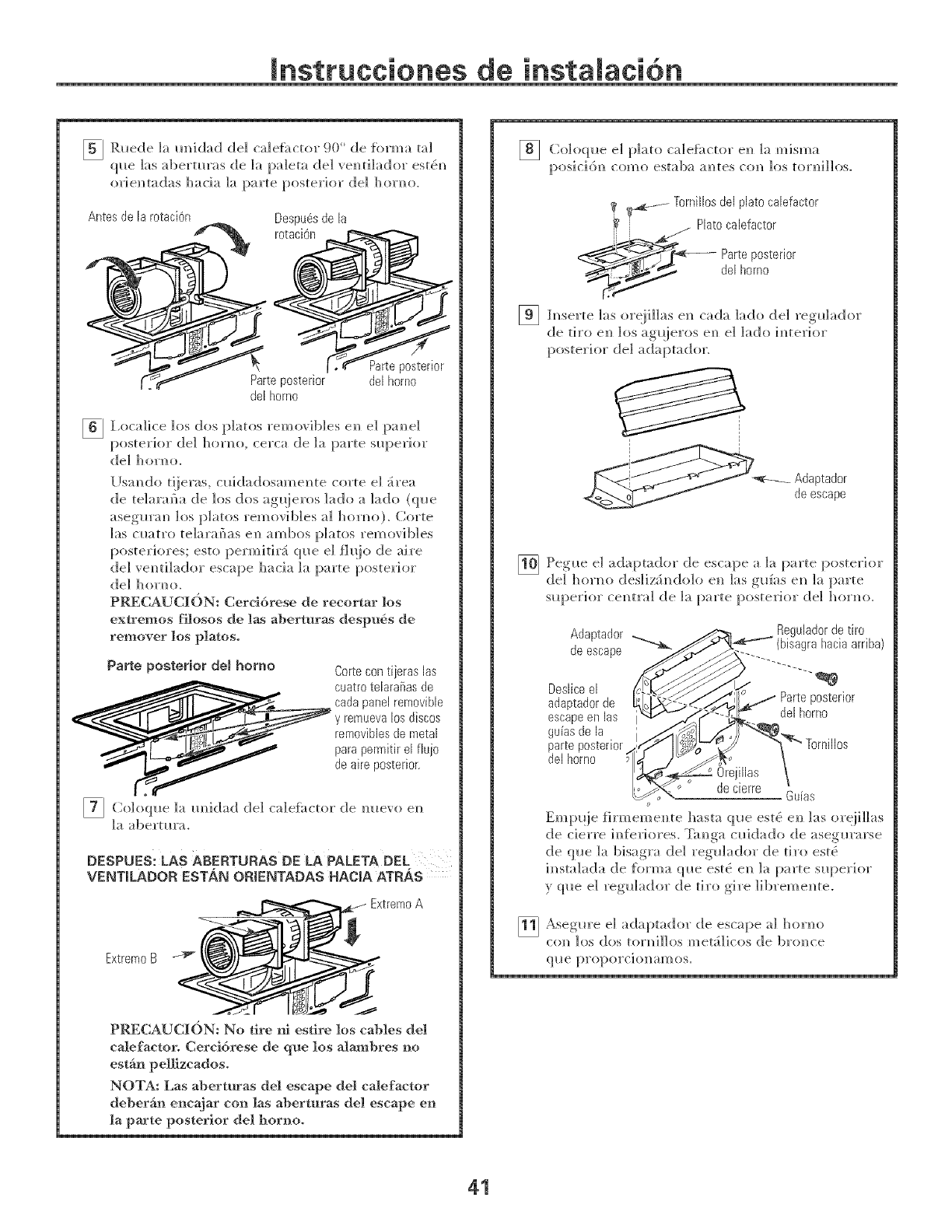
5_ Ruede ]a m_idad de] ca]e[_ctor 90 ° de [orma tal
que ]as abertm'as de ]a pa]eta de] vem_ti]ador este£m_
orie]_tadas hacia ]a parte posterior (]el hor]_o.
Antes de la r0taciOn Despub.sde la
Pate posterior
del homo
Parte posterior
del homo
[] l,oca]ice los dos jp]atos remo;ib]es eN_ el pam_e]
posterior de] hor]_o, cerca de ]a parte superior
del hondo.
l Ismldo t!ieras, cllidadosame_]te corte el _rea
de telarafla de los dos ag_ieros ]ado a ]ado (ql_e
asegmw] los platos removib]es a] horm_o). Corte
]as cl_atro te]arai_as el_ ambos p]atos removib]es
poster]ores; esto permitir_ (p_e el fil!io de aire
de] vem]ti]ador escape hacia ]a parte posterior
de] ]]orm]o.
PRECAUC][t)N: Cerddrese de recortar los
extremos filosos de las aberturas despu6s de
remover los platoso
Parte posterior deB homo Cortecontijeras las
_ uatro teJarafias de
cada paneJ rem0vibb
y remueva J0sdiscos
rem0vibbs de metal
para permitir el fiuj0
de aire posterior
[] Coloql_e la m]idad de1 caleii_ctor de m_evo en
la alaert ta'a.
DESPUES: LAS ABERTURAS DE LA PALETA DEL
VENTILADOR ESTAN ORIENTADAS HACIA ATRAS
Extrem0A
Extreme B _i
PRECAUC]ION: No tire m estire los cables del
calefactoro Cercidrese de que los alambres no
estgn pel]izcadoso
NOTA: Las aberturas del escape del calefactor
deber_in encajar co_] las abertnras de! escape en
la parte posterior det bornoo
] Co]oqlle e] p]ato ca]e[i_ctor ell ]a misma
[:)osic]6]_ como estaba a_tes co]_ los tor]_]]]os.
_ .... Tornillos deJplato cabfact0r
_¢ _ Plato calefact0r
_22_-_t _-_-- Parte posterior
__ del h0rn0
[] h_serte 1as ore]i]]as e_ cada ]ado de] reg_lador
de tiro e]_ ]os ag_!]eros e_ e] ]ado i_terior
posterior (]el adaptador.
ptador
deescape
[_}] Ipeglle el aria :_tador de esca :_ea ]a }arte >osterior
, I .... _ I I ,
de1 hondo desliz_,_dolo ell 1as g_[as e,_ la parte
s_q::_erior ce]_tra] de ]a parte posterior de] hor]_o.
Adaptad0r
de escape
Deslice el
adaptad0r de
escape en las
guias de la
parte posterior
del homo
Regulador de tiro
gra hacia arriba)
posterior
del homo
_rnillos
6uias
0
Eml:mie firmeme_]te hasta que estt) en_ ]as oreiillas
de cierre i_{_riores. Ta_ga c_idado de asegm'arse
de (p_e ]a bisagra de] reg_lador de tiro est5
i_sta]ada de {i_rma q_e est& e]_ ]a parte s_[:>er]or
y q_e e] reg_]ador de tiro g]re ]ibreme_te.
[] Asegm'e el adaptador de escape al hor]_o
co_ los dos tor]_]]]os met;i]icos de brtmce
41
[nstrucciones de
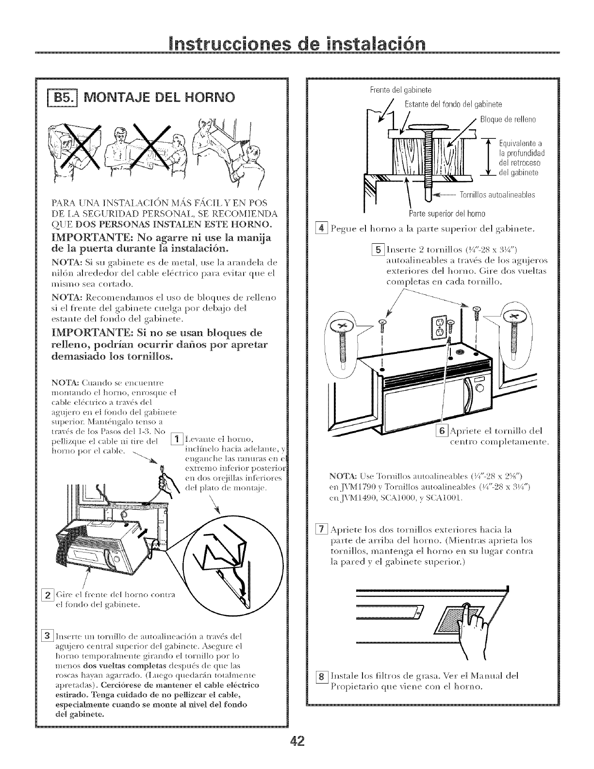
MONTAJE DEL HORNO
PARA UNA INSTALACI()N M,{S F,{CH, YEN POS
DE I,A SEGURIDAD PERSONA1,, SE RECOMIENDA
Q{IE DOS PERSONAS ]{NSTALEN ESTE HORNO.
IMPORTANTE: No agarre ni use la manija
de la puerta durante la instalacidn.
NOTA: Si sl_ gabh_ete es de metal i_se ]a arm_dek_ d!e
m_ildm_ah'ededor de] cable ekSctrico para evitar ql_e el
H?iSH?O se_ col't_do.
NOTA: Recom em_dam os e] I,so de b] oq I*es de rdl en o
si d freN_te de] gabim_ete clm]ga pot deb_io del
estam]te de] _imdo de] gabinete.
IMPORTANTE: Si no se usan bloques de
relleno, podr_an oeurrir dafios por apretar
demasiado los tornillos.
NOTA: Cua_*do se e]_cuem]x
montando el horm), e]_rosq/m el
cable eldctri(o a t_'_ds de1
ag_{jero e_] el [bndo det gd_it_ete
E_ h_s( r_( m_ mrnil[o d( amoalineaci6n a u'_'_ds d(I
ag_j_ ro cemrat sup_ riot d(l g_bin( t_. Asegme e1
hoH_o t(mpo_almeme gi_ redo el tornillo po_ lo
me_os dos vueltas eompletas despuds de que las
roscas havan agarrado. (I_uego queda%n tota[mente
_pretadas). Cereidrese de mantener el cable el6ctrleo
estlradoo Tenga culdado de rm pellizcar el cable,
espeeiaImente e_ar_do se mor_te M ravel del for_do
del gablr_ eteo
Frente del gabinete
Estante de[ fond0 de[ gabinete
BI0que de rellen0
T quivaiente a
[a profundidad
de[ retroceso
del gabinete
Tomi[[0saut0a[ineables
Parte superior de[ homo
4_J Peg_e el homo a]a parte superior de] gabi_ete.
E_ [_]serte 2 torni]]os (Y_'-28 x3Y_")
autoa]i_eab]es a travets de los ag_!ieros
exteriores (]el horror. (;,ire dos vueltas
comp]etas e_ cada tor_[Ho.
Apriete e] torni]]o d!el
NOTAs Us( 'Ii>millos mloalineabk_s (_1"-28 x 2%')
e_.JXM1790 } 'Ii_rniJlos m_oalineab/es (gt'-28 x 3Yt")
(_.[VM_490, SC\_000, } SC\100_.
[] Apriete los dos tornillos exteriores hacia la
parte de arriba de] ]]or_o. (Mie_tras aprieta ]os
torl/i]los, ma_?te_?ga el hor]?o e_] sil ]llgar c(mtra
la pared y el gabi_ete s_q)erior0
_ h]sta]e los fi]tros de gmsm vet e] Mamma] d!e]
Propietario que "_'ie_e c(m e] ]_oH_o.
mnstrucciones de
RECIRCULACi6N !sinconductode ,entiUaci6.l
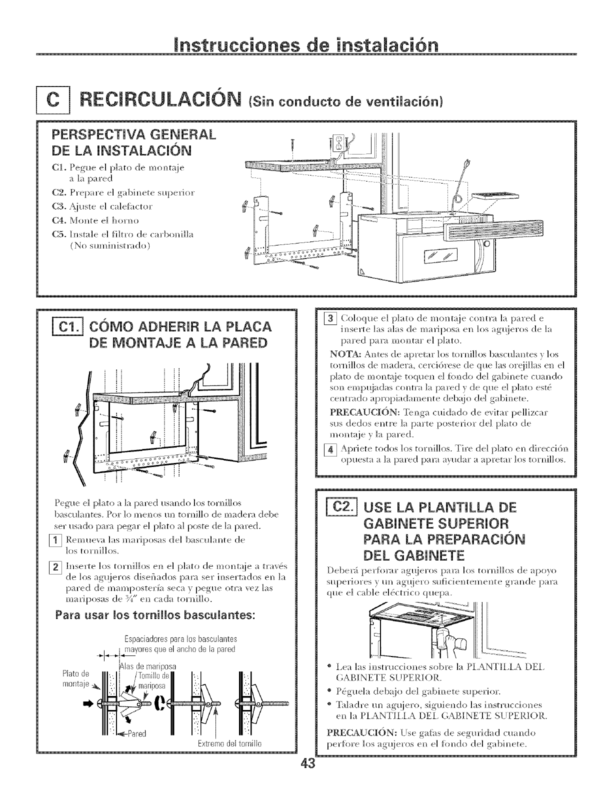
PERSPECTJVA GENERAL
DE LA INSTALAClON
C1. Peg_e e] plato de mom_t_ie
a ]a pared
C2o Prepare e] gabim_ete sl_perior
C3o A._uste e] ca]e{;_ctor
C4. Mo_te el hor_o
C5. Insta]e el }i]tro de carbom_i]]a
(No sm_dmdsm_do)
COMO ADHERJR LA PLACA
DE MONTAJE A LA PARED
Peg_*e e] plato a ]a pared usm_do los tortoni]los
bascldm_tes, Pot ]o mem_os m_ torm_]]]o de madem debe
set I*sado prow pegar e] plato a] poste de ]a pared.
[1 Reml_eva ]as mariposas de] basodam_te de
los tortoni]los.
_ h_serte los torni]]os en e] plato de mont;!ie a tray,s
de los. ag_ieros_. .......disefiados [)ara .........setim_sertados em_ ]a
[)ared de mare [)ostei'[a seca _,t)eg_le_ otra vez ]as
mariposas de _" en_ cada torni]]o.
Para usar los tomiHos bascuUantes:
Espaciad0res para los basculantes
+L,_i]r_ayores que el ancho de la pared
I '_
i
_las de marlposa
Plato de
montaje
Extrem0 del tornill0
[] Coloque el plato de mo_m_ie co_m_ la pared e
i_serte ]as alas de mariposa en los ag_ieros de ]a
pared para mop, tar e] plato.
NOTA: Antes de apremr los torid]]os bascldm_tes v los
tor_i]]os de madera, cercidrese de q_e ]as or@Has en e]
plato de monmie toque_l el fimdo de] gabh_ete c_;mdo
son emp_]adas co_tra ]a pared y de q_e e] plato este_
center,do apropiadame_te deb_!jo de] gabh_ete.
PRECAUCI(_)N: Te_ga c_ddado de evitar pe]]izcar
s_s dedos entre la parte posterior de] plato de
m o_ mie y la pared.
_ Apriete todos los torni]]os. Tire de] plato e_ direcci6n
o[:mesta a ]a pared para ay_dar a apretar ]os torni]]os.
USE LA PLANTILLA DE
GABINETE SUPERIOR
PARA LA PREPARACK)N
DEL GABINETE
Deber_ per_b_r ag_!ieros pa_ los torni]]os de apoyo
s_periores y m_ agqiero s_{icienteme_te grm_de para
q_e e] cable e]e}ctrico quepa.
® I,ea las i_sm_ccio_es sobre la PI,ANTII,IA [)El,
GABI NETE S[ IPERIOR.
® P_g_e]a deb@_ de] ,gabi_ ere ,su I_eri°r-
® T:dadre mi ag_@ro,, ,sig_del_do las i_/str_./ccio_ies
e_ ]a PI,ANTII,I,A [)El, (;¢BINETE SIJPERIOR.
PRECAUCION: [Jse galti_s de seg_ridad c_a_do
perfore los agueros_.! e_ e] f(mdo de] ,gabi_ete-
43
mnstrucciones de
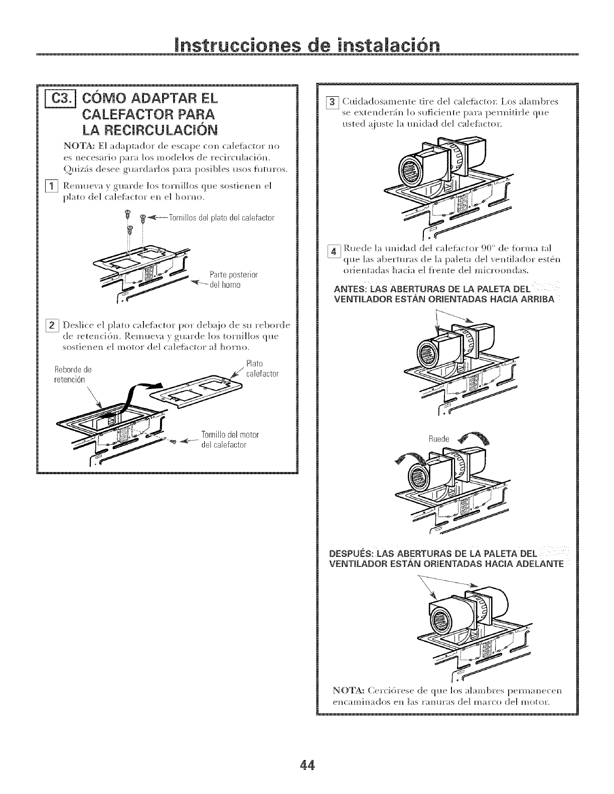
[-_ C6MO ADAPTAR EL
CALEFACTOR PARA
LA RECJRCULACJ6N
NOTA: El _daptador de escape con cale{i_ctor no
es necesario para los modelos de recircl_l_cidn.
()J_iz_s desee g_rdar]os para posib]es i_sos flmaos.
1_ Reml_eva y g_rde los torni]]os ql_e sostienen e]
plato de] ca]e{i_ctor en e] homo.
_._----Tornillos del plato del calefactor
II
Des]ice e] plato ca]e{i_ctor pot deb_io de su reborde
de retenci6n. P,emueva } guarde los torni]]os que
sostienen e] motor de] _a]eii_ctor a] homo.
Plato
Reborde de _calefactor
retencidn
Tornillo del motor++_deJcaJefactor
[] Cuid;_dosamente tire de] c;de{i_(to_: l,os ahm_bres
se extender_n 1o su{iciente para permitir]e que
usted _iuste ]a m_idad de] ca]eti_ctor.
orientadas hacia el frente del microondas.
ANTES: LAS ABERTURAS DE LA PALETA DEL
VENTILADOR EST._N ORJENTADAS HACIA ARRIBA
Rue@
DESPUES: LAS ABERTURAS DE LA PALETA DEL
VENTILADOR ESTAN ORIENTADAS HAC_A ADELANTE
NOTA: Cerd6rese de que h>s ahm_bres permanecen
44
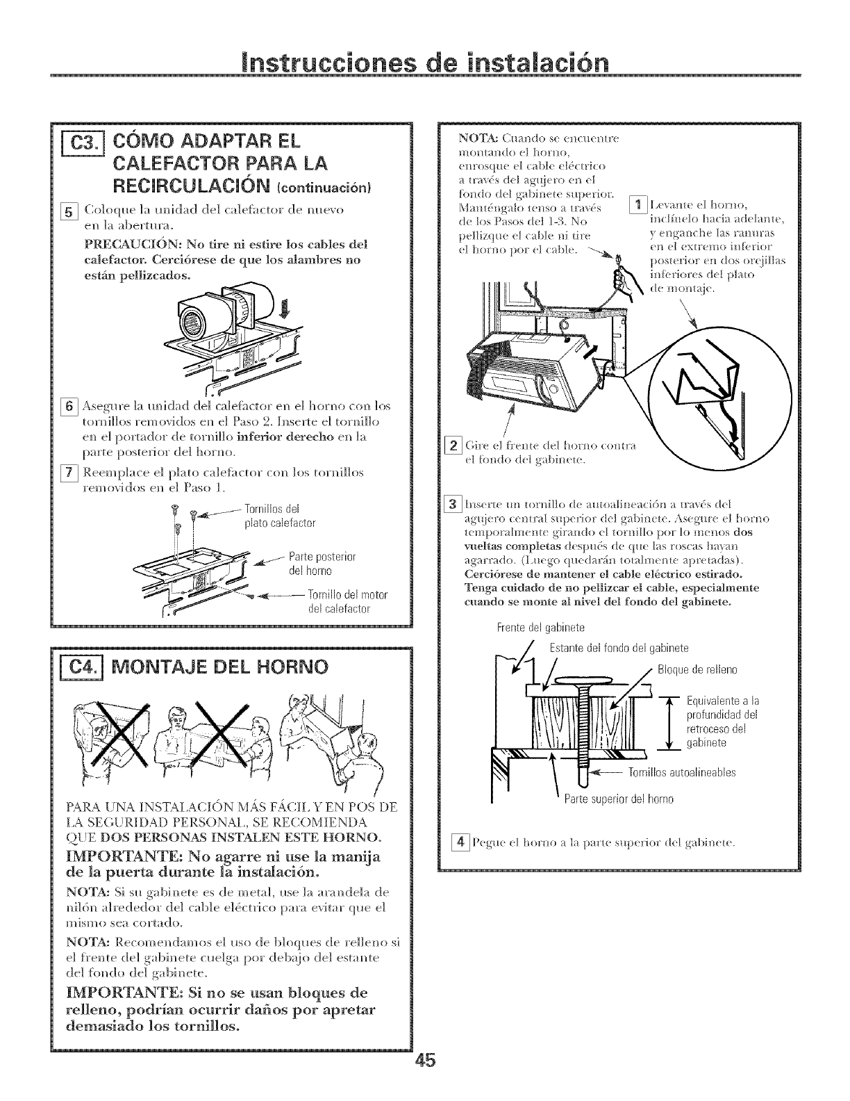
Jnstrucciones de
C()MO ADAPTAR EL
CALEFACTOR PARA LA
RECJRCU LACJ6N Icontinuaci6n/
[] Co]oql_e la m/idad de] cale{i_ctor de m_evo
el/ ]a abertm'a_
PR_]CAUCION: No tire m esdre los cables del
calefactor. Cerci6rese de que los alambres no
estgm pdlizcados.
[_ Aseg_lre ]a m/id!ad! d!e] ca]e{k_ctor el/e] hor]/o col/ los
torm/i]]os removidos era/e] Paso 2_ Inserte e] torm/i]]o
era/ el portador de toH/i]]o hqferior derecho era/]a
parte poste_i or de] horm/o.
7_ Reemplace e] ca]eli_ctor ]os torl/i]]os
p]ato COl/
reH/ovidos el/ e] Paso ].
1_ g_. ....... Tornillosde[
i platocalefactor
--f arteposterior
de[homo
__Z-_ _----- Tornii,odel motor
rT_,.f,,,,_ de[caiefactor
MONTAJE DEL HORNO
PARA [/NA INSTAIACION M,4S F,;ff;Ii, YEN POS DE
I,A SEGURIDAD PERSONAl,, SE RE('.OMIENDA
Q[IE DOS PERSONAS INSTALEN ESTE HORNO.
IMPORTANTE; No agarre ni use la manija
de la puerta durante la instalacidn.
NOTA: Si sll gabim/ete es de metal, Ilse ]a aram/deIa de
m/i](5]/aIrededor de] cable e]_ctr]co para evitar qlle el
mismo sea cortado.
NOTA: Recomel/damos e] Ilso de b]oql_es de re]]eno s]
e] _}'el/te de] gabim/ete clm]ga pot deb:{}o de] estaN/te
de] {imdo de] gabim/ete_
IMPORTANTE: Si no se usan bloques de
relleno, podr_an oeurrir dafios por apretar
demasiado los tornillos.
45
_ h]sel'{e /[]] tOl'ni][o de t_ltoalb/eaci6]! _l tl" t'_('s de[
agl{iero cemral superior d(t gabine_e. Asegur( el horm>
tempor_dmente gira]_do eI tornillo pot to m_]]os dos
wmltas completas despuds de <]_*elas rosc _s haxm
agar* _do. (L_*ego (pmda*fi_] tomlmem( _pr(md _s).
Cerei6rese de mantener el cable el6ctrlco estlradoo
Tenga e_ddado de rm pelllzcar el cable, especlalmeme
cuar_do se mome al r_ivel del for_do del gablrmteo
Frente de[ gabinete
Estante del fondo de[ gabinete
Bloque de relleno
T quivaientea la
profundidadde[
retrocesode[
gabinete
Torniiiosautoalineables
Partesuperiorde[homo
)(g'II( (] ho!'!_o _t I}l ]{)}TH'{( S/IN( l']{Of d(] _{bi]/ele.
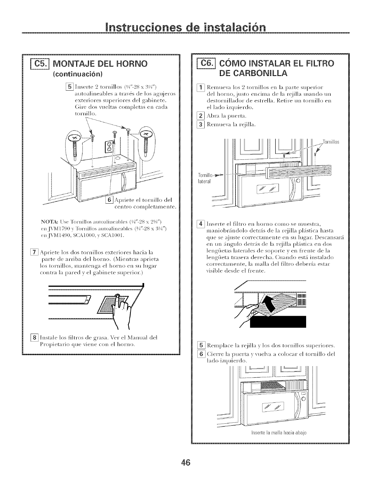
Jnstrucciones de
MONTAJE DEL HOF{NO
{continuaci6n}
E_ h]serte 2 tor]li]]os (I//L28 x 3_/_")
alaoa]im_eab]es a travds de los _g_ieros
exteriores sl_periores de] gabim_ete.
(;ire dos vl_eltas comp]etas eN_c_(;[a
torm_illo.
_priete e] tor]_i]]o del
cem?tro comp]etamen?te.
NOTA: [Js_ "['ornilIos amo dil/eabl_ s (_/'-23 x 2_J _)
n,l V[\:1! 790 } "['_H]illos a_o _ti] _( _t_]cs (V*"-28 x 3J/_")
(n ,]VM ! 490, S(;X ! 000, y S(_\ 10(}!.
[] Apriete los dos tor]_i]]os exter]ores hacia la
parte de arriba de] ]]orm_o. (Miem_tr_s aprieta
los tor_i]los, maN_tem_ga e] hor_o em_ sl_ h_gar
co_tra ]a pared y el gab]here s_perior 0
_ l_sta]e los []]tros d!e gr:_sa, vet e] Mamm] de]
Prop]etarh_ (]lie v]e]_e c(m e] hon]o.
COMO INSTALA EL RLTF{O
DE CARBONILLA
_ Rem_eva los 2 toH_i]]os e]_ ]a parte superior
dd ]]or_o,justo el_cima de la reiiIIa usa_do m_
deston_i]]ador de estre]]m Retire m_ toH_i]]o e_
e] ]_do izquierdo.
_ _kbra ]a [merta.
[] Rem_eva ]a reii]]a.
_ h_serte e] filtro e_ horm} como se m_lestra,
mm_iobrS_do]o detrSs de ]a reii]]a pL_stica h_sm
q_e se _i_ste correctame]/te e_/ s_l ]_lg_/r. Descm_sar_
e_ m_ _i_g_]o detr_is de ]a reii]]a p]_istica e_ (los
]e]_g{?etas ]atera]es de soporte y e_ f_'e]_te de ]a
lel_g£_eta trasem derecha. C4m_do est_i i_stalado
correctame_te, la ma]la de] filtro deberfa estar
visible desde e] f}'e_te.
/
lilHliJ
[] Remp]_ce ]_ reii]]_ } los dos ton_i]]os s_q:_eriores.
E_ Cierre ]a puerta } ",'ue]','a a co]ocar e] tor]_i]]o de]
Inserte la malla hacia abajo
46
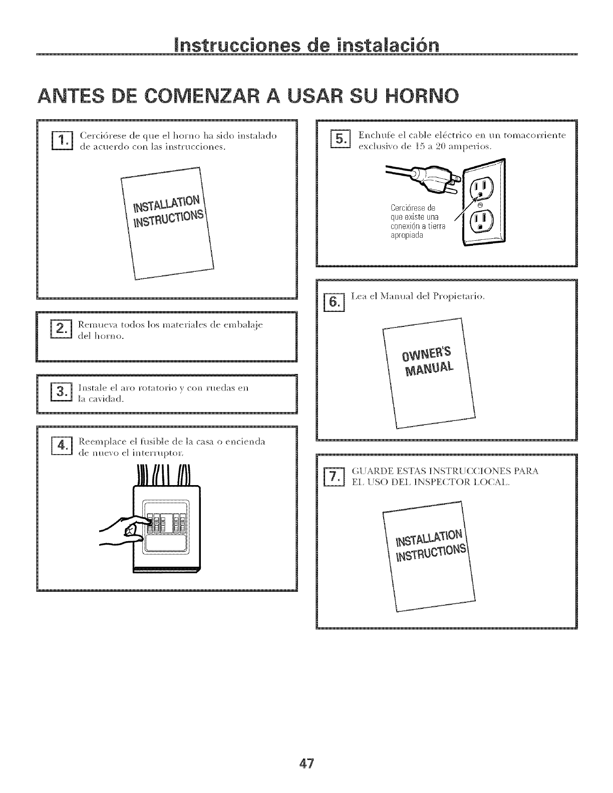
mnsttucciones de
ANTES DE COMENZAR A USAR SU HORNO
-] Ce_ci_,_ese de _-_l_e el ho_l_o h_ siclo im_st:_L_clo
c[e _;_cHel_(_[o COm_ l_s im_st_H(ciol_es.
_ eml_e_';_ to(los los m_te_i_les de emb_l_ie
c[el hoH_o.
1
--_ Reempl_]ce el f_sil)le de 1_ c_s_] o e]_cie]_da
de m_e'_'o el im_te]Tlol){o] _.
IllIIIIIBI
'_ Em_chl_'e el c;_I)le el_ctl"ico e_ im tom_co_T]e_te
(;_!_RDE EST¢S INSTR{!CCIONES P_R_
EL _SO DEL _NSPECTOR LOCAL.
47

4%40453 I (06-05JR)
P]'i m_ted i m_Ko]'e;_
