GE Range Hood Manual L0406352
User Manual: GE GE Range Hood Manual GE Range Hood Owner's Manual, GE Range Hood installation guides
Open the PDF directly: View PDF ![]() .
.
Page Count: 20
www.GEAppliances.cem
Safety Information ........ 2, 3
Operating/Care and
Cleaning Instructions
Charcoal Filters .............. 5
Grease Filters ................ 4
Hood Lights ................ 5
Hood Surfaces ............... 5
Stainless Steel Surfaces ........ 5
Vent Controls ............... 4
Installation Instructions ...6-15
Troubleshooting Tips ....... 16
Consumer Support
Consumer Support ........... 90
X4'arranty .................. 19
JVS)5
JV536
JV565
JV566
JV635
JV636
jq!665
3q7666
Write the model and serial
numbers here:
Model #
Serial #
Find these nmnl_ers on a label
on the back wall of the hood.
iii!
164D4290P353 49-80200-3 02-04 JR
IMPORTANTSAFETYINFORMATION.
READALLINSTRUCTIONSBEFOREUSING.
SAFETYPRECAUTIONS
WARNING-TOREOUCETHERISKOFFIRE,
ELECTRICSHOCKORINJURY TOPERSONS,OBSERVE
THEFOLLOWING:
A. Use this unit onl} in the rammer intended b) tile
manutimtm'ec If you hmv questions, contact the
irlan tltilct tire/;
B. Befi)re seIMcing or cleaning unit, switch po_vwr
off at serxice panel and lock the service
disconnecting means to prevent power fl'om
being switched on accidentally. When the set\ice
discomlecting means camlot be locked, securel}
thsten a prominent warning dexice, such as a tag,
to the seIMce panel.
C. Do not use this unit with an) solid-state speed
control device.
D. This unit must be grounded.
CAUTION-FORCENERALVE,VT/_T,VC
USEONLY.DONOTUSETOEXHAUSTHAZARDOUS
OREXPLOSIVEMATERIALSAND VAPORS.
WARNING- TOREBUCETHERISKOF
INJURY TOPERSONSIN THEEVENT OFA RANGETOP
GREASEFIRE,OBSERVETHEFOLLOWING*:
A. SM OTHER FI AMES with a close-fitting lkt, cookie
sheet or metal tray, then turn off the bm'ne_:
BE CAREFUI, TO PREVENT BURNS. If the
flames do not gx) out immediate]y, EX,ACUATE
AND CA[ i, THE FIRE DEPARTMENT.
B. NEVER PICK UP A FIAMING PAN--3ftu ma)
be burned.
C. DO NOT USE \\_4TER, inchlding _vt dishcloths
or to_vls--a violent smam explosktn will result.
D. Use an extinguisher ONIXitl
1. Ytu know you hmv a (;lass ABC extinguisher;
and you alread} know how to operate it.
2. The fire is small and contained in the area
where it started.
3. The fire department is being called.
4. You can fight the fire with your back to an exit.
* Based on "_tchen Firesatbt} Tips" published
b) NFPA.
WARNING-TOREOUCETHERISKOFA
RANGETOPGREASEFIRE:
A. Ne_vr leme surfiwe units unattended at high
settings, goilo_vI_ cause smoking and gTeas)
spillovet_ that ma) ig_lim. Heat oils slowl) on
low or medimn settings.
B. Always turn hood ON when cooking at high heat
or when cooking flaming foods.
C. Clean ventilating tiros fl'equentb'. Grease shouM
not be allo_vd to accumulam on tim or filmr,
D. Use proper pan size. N_l),s use cookwm'e
appropriate titr the size of the surtilce element.
WARNING-TOREOUCETHERISKOFFIRE,
ELECTRICSHOCKORINJURY TOPERSONS,OBSERVE
THEFOLLOWING:
A. Installation _)I'k and electrical wiring must be
done b) qualified pelion(s) in accordance with
all applicable codes and standards, including
fire-rated construction.
B. Sufficient air is needed tin" proper combustion
and exhausting of gases through the title
(chimne}) of filel burning equipment to pre_ent
back dratiing. Follow the heating equipment
manufhcturer's guideline and safet) smndm'ds
such as those published b) the National Nre
Promctktn Association (NFPA), the Amei'ican
Societ) titr Heating, Refl'igeradon and Air
Conditktning Engineers (ASHRAE) and the
local code authorities.
C. When cutting or drilling into wall or ceiling, do
not damage electrical wiring and other hidden
utilities.
D. Ducted thns must alwa)_ be vented to tile
o tltdooi's,
WARNING-TOREOUCETHERISKOFFIRE,
USE ONLYMETALDUCTWORK.
Do not attempt to repair or replace an) part of
)'our hood unless it is specificall} recolnlnended iI1
this gukte. 'All other selMcing should be referred
to a qualified technician.
READANDFOLLOWTHISSAFETYINFORMATIONCAREFULLY.
READAND SAVETHESEINSTRUCTIONS
2
INSTRUCTIONSDESECURffEIMPORTANTE$.
USEZ TOUTE$tES/NSTRUCT/ONSAVANTffUT/USER _CEA_li_.oo=om
PRCcCAUTIONSENMATIecREDESCcCUR/TCc
t
........,_ AVERTISSEMENT-mRRtOUIRELEAVERTISSEMENT-RtOUISEnE
RISQUED'INCENDIE,DESECOUSSEELECTRIQUEOUDE RISQUED'UNFEUDEGRAISSEStIRLASURFACEDE
BLESSURECORPORELLE,OBSERVEZLESPR£'CAUTIONS
SUIVANTES:
A. N'ufi]iscz cot apparel] qtte dc ]a mani,St'c prdvue pro le
lidMcant. Si ','(ms a'a.'z des qtl¢'StJOl/S, appelez k' Jitbricant.
B, ,\We[It de rdl)_ll:er Otl de lletto}t'r \'otre appareil,
ddbrai/chez le cot[/';lllt au nivcatt du panneau de service
et vcrrouillez les mdcanismes de d('brmlchemem de
S('I:\JC(! pO(ll: @iter [(Hit bl'_lllchel/l(!l/t accidente] att
co/lral/t. Ni \_)/IS lie po/l_'z pas \_TFO/lilleF les
mdcanismes de ddbnmcheumnt de service, attachez
soignettselnent/ill avcrtisse]l/ellt bien visible, col_/i/le
ttile dtiquette, all ])ai/l/eatl de service.
C. N'utilisezjamNs cet appareil avcc un mdcanisme de
rdgl;ig-e de la \itesse h semi-coiMucteurs.
D. Cet appareil dolt ,Stre bien mis 5 la terre.
ATTENTION- UNIOUEMENrAUSACEOE
VENTILATIONGE-NE-RALE.N'UTILISEZJAMAISPOUR
L'E-CHAPPEMENTDEMATIE-RESETDEVAPEURS
EXPLOSIVES.
AVERTISSEMENT-POURR_OUIREtE
RISQUEDEBLESSURECORPORELLESI DELAGRAISSE
PRENDFEUStIRLASURFACEDECUISSONDUFOUR,
SUIVEZLESINSTRUCTIONSSUIVANTES*:
A. I(TOUIq;EZ I.ES I:I,AMMES a_e( tm (ott'v(!r(h: q/li
(O]/Vi(!ll[, till(! t61e _ l)is( uJts Oil L11/ ])latealt (!l/nl('tal,
puis ('migm_z le brfllem: I:AITES glEN ,_ITENTION
I)E NE BkS \OU S BRI_JI,ER. Si les tlammes lie
s'dteignem pas immddiatement, SORTEZ ET APPEI.EZ
I.ES POMPIERS.
B. NE DI{PI.ACEZJ_\M\IS UNE CASSEROI,I E ()UI
FI .\M gE - \Oils po mez xr()ttS br tt](}12
C. N'UTII.ISEZJAM\IS I)'EkU, ell patti( ulier de serdette
ou d(! ( hiitbn mouilld - il se produira un(! explosion
vJolellt(} de vapcur l)rttlal/te.
D. N'UTII.ISEZ UN EXTINCI'ELIR que si :
lo _0/lS _/_,(?Z ILl/ eXtill( te/Ir (]e ( ]aSSe Age (}t votts sa*,ez
( omment l'ufiliser;
2. I.e t{_u est r('duit et (onfind _ll'endroit off il a
(()filial(fill (';
3. V0us avez d(jh appel(' les pompiers;
4. _O/lS (()I/lbat[(!Z leS f[_tI/ll/lI.!S (!l/ tO/ll'lla]/t 112 (10S _'1
( LI/IZ sortie.
* gasd snr l'ou'vrage infimld <<Kitthen Fire Sati:ty Tips>>
publi(' par la NI:E\.
CUISSONDUFOUR:
A. Ne laissezjamais _ms surwillancc los uniE('sde cuisson de
sur/iuc it une tcmpi, rature (,hw(*x_.Is' bouillonm'mcnt
o( CkkfliOlllledes d('bOl'(l(!l//el/tS tilll/alllb et gTaisseux (]/li
pemvnt prendrc Ji'u. Chau//bz _/li:tt doux les substances
huil,.:uses, m'cc un rdgl_/ge bas ou moycn.
B. Mettez tot!jotnTs la hotte el/m_u'che quand mus cuisinez
it haum tempgTature ou qland vous cuisinez des
aliments qui om des flmnmes.
C. Netlo\cz les mdcanismes de _vndlation ti'6queumlent.
I1 ne [imt pas permettre une accumulation de graisse
sur le ventilateur ou sur le fihre.
D. Utilisez line casserole de bonne taille. I-Itilisez toujoltrs
ttn ustensil(! de cuisine qui COlIVielllle all diam6tre de
l'/'ldment de cuisson.
AVERTISSEMENT-pOURRtOUIREtE
RISQUED'INCENDIE,DESECOUSSEE.LECTRIQUEOUDE
BLESSURECORPORELLE,OBSERVEZLESPRE.CAUTIONS
SUIVANTES:
A. Vous/t('x('z Jidr(' ('x/'(ut('r t/ms l('s tra\attx d'insufllatMn
et de (2d)l_/g(' dlectrique par une personlle qualifide,
C()lll[)lTl/l('ll/ellt _/ tOllS l(:s codes et les l/()Fl//eS eII
dgltem; ell particulier ce/tx de construction relatig
aux incendies.
Bo rOllS d('\_.'z assez d'air pour ktVOil" /lIle bOl/l/(!
col/lbusdoll et permetlre l'd\ilcttath)ll des g;iz par le
collduit de cheminde du n'_at('l:iel de con'_b/lstioil (ill
C_/l'b/IFk/l/t, 3Jill d'6viter loll[ retO/ll? (l'kliK S/li\_.'Z 1(!S
directives du ]hbricant de mat('riel de combustion et
les normes de s6curitd comme celles publi('es par la
National Nre Protection Association (NFI{\),
l',\merican Society ]br Iteafing, Re/i'igerafion mM
Nr Conditioning Engineers (ANIRAE), aJnsi que les
modalitds des codes locaux.
Co _i VO/IS thites (lIl [F()/l O/l Itne O/lV('lTtllre d_IIs till Ill/IF
ou un plaJbnd, n'endolmnagez pas les tils dlectriques
et les mitres installations cach('es de service public.
D. Vous dc_vz t/)/{jours alimemer les v('nfilateurs darts les
conduits en air el/pr/)v(.nallce de Fextdriem:
AVERTISSEMENT-pOURR_OUIRE
LERISQUED'INCENDIE,N'UTILISEZQUEDESCONDUITS
ENM_'TAL
N'ess_Ewzjamais dc _emplkwer ()It (h' rdparcr un i'll'merit
(l(' \/)tl'(' h()tt(' si l(' t)l'('S('llt llKIll/l(!l Xl(' l(' 1X'C()I]lll/_lll(]('
pas exl)ressdment. "Ibut autr,.: entreden doit £'tre eJti:ctu6
par un technicien qttalili&
LISEZETSUIVEZATTENTIVEMENTCESINSTRUCTIONS.
LISEZETCONSERVEZCESINSTRUCTIONS 3
Usingthe hoodcontrols.
Throughout this manual, features and appearance may vary from your model
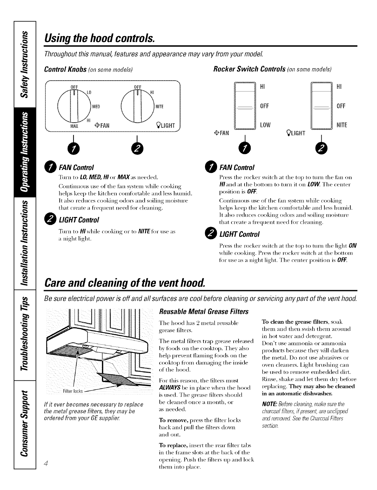
Control Knobs (on some models) Rocker Switch Controls (on some models)
OFAN Control
Turn to LO,MED, HIor MAX asneeded.
(_onfinuous use of the tim system while cooking
helps kee I) the kitchen comflwtable and less hmnid.
It also reduces cooking o(lo_ and soiling moisture
that create a fl'equent need for cleaning.
OLIGHTControl
Tm'n to HI while cooking or to NITE t0r use as
a night light.
Hi
OFF
LOW
€#FAN _LIGHT
O ,
Hm
OFF
NTE
OFAN Control
Press the rocker switch at the top to turn the tim on
HI and at the bottom to turn it on LOVV.The center
position is OFF.
Continuous use of the tim system while cooking
helps kee I) the kitchen comt0rtable and less humid.
It also reduces cooking o(lo_ and soiling moisture
that create a fl'equent need fi)r cleaning.
OLIGHTControl
Press the rocker switch at the top to turn the light ON
while cooking. Press the rocker switch at the bottom
fi)r use as a night light. The center position is OFF,
Careand cleaning of the venthood.
Be sure electrical power is off and all surfaces are cool before cleaning or servicing any part of the vent hood.
If it ever becomes necessary to replace
the metal grease filters, they may be
ordered from your GEsupplier
ReusableMetal Grease Filters
The hood has 2 metal reusable
grease filte_.
The metal filte_ tral ),grease released
1)_fl)ods on the cooktop. The) also
help prexent flaming toods on the
cookto ) fl'om damaging the inside
of the hood.
For this reason, the filtet_ inust
ALWAYS be in place when the hood
is used. The grease filte_ should
be cleaned once a month, or
as needed.
To remove, press the filter locks
back and pull the filte_s down
[1110 Otlt,
To clean the grease f'flters, soak
them and then sMsh them around
in hot water and detergent.
Don't use [llllll/oni[l oi" [lllli/loni[l
products because they will darken
the metal. Do not use abrasives or
oven cleane_5. I,ight brushing can
be used to remove embedded dirt.
Rinse, shake and let them dry befi)re
replacing. They may also be demled
in an automatic dishwasher,
NOTE."Before c/eanlbg make sure the
charcoalfilters, if present, am unclipped
and removed Seethe CharcoalFilters
seCtl'On.
4
To replace, insert the rear filter tabs
in the fl'ame slots at the back of the
opening. Push the filte_ up and lock
them into place.
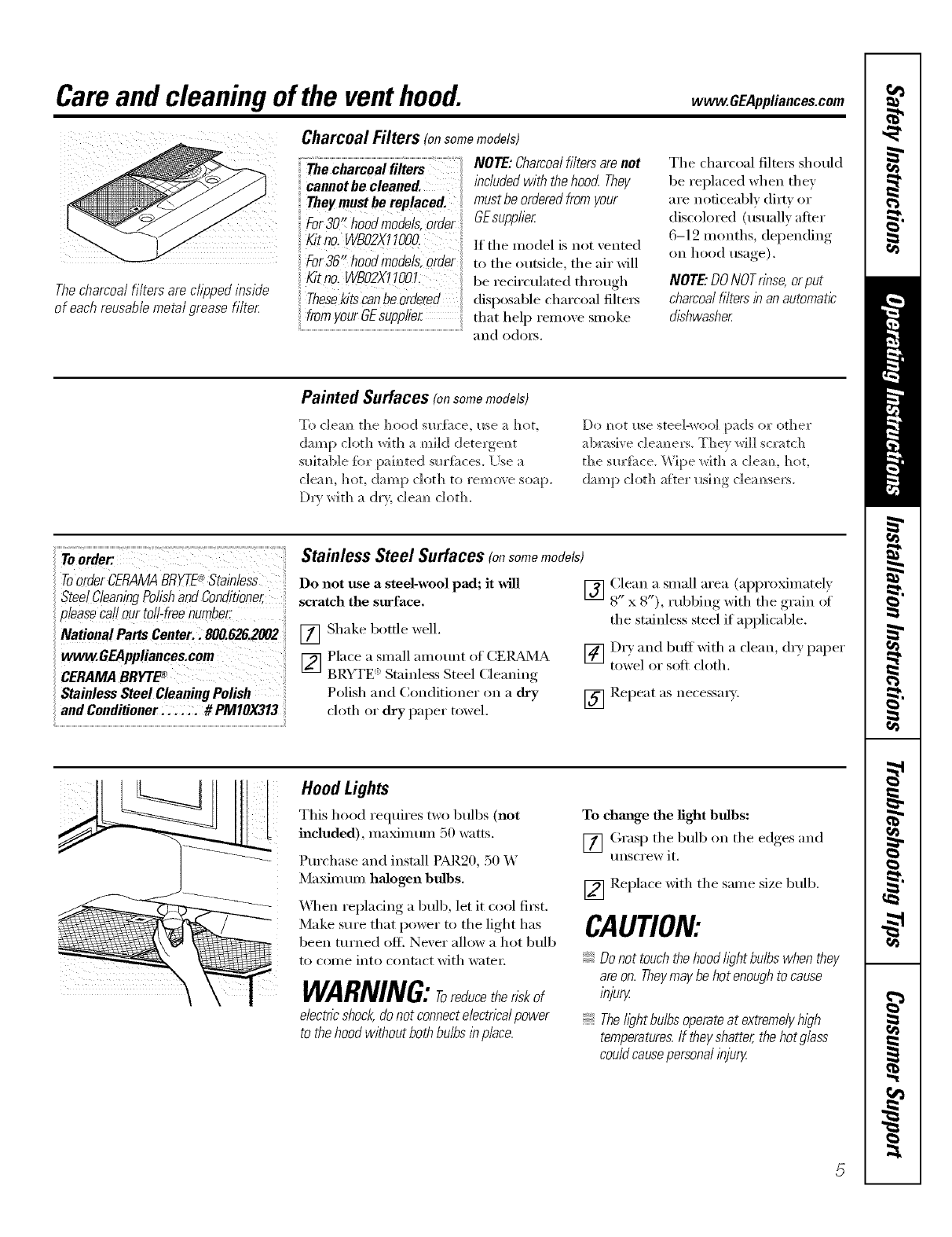
Careand cleaning of the venthood. www.GEAppliances.com
Thecharcoal filters are cfiooed nslde
of each reusable metal grease filter
Charcoal Filters (onsomemodels)
The charcoai filters :: : : NOTE: Charcoal filters are not
cannot be cleaned, included with the hood They
They must be replaced, must be ordered from your
For30 hood models,Order GEsupplier
K,tno lgoo .them. lelis,,,,t.e,,te l
For36 hOM models, Order to the ,,utside, the air,,'ill
Kitno. WBO2X1100L be recirculated through
TheSekits canbe ordered disposable charcoal filte,_
from your GEsupplier that help remove smoke
.....................................................................................................................................................................................and odoi_.
The charcoal filters should
be replaced when they
are noticeably dirty or
discolored (usually after
6-12 months, depending
on hood usage).
NOTE'.DO NOTrinse, or put
charcoal filters in an automatic
dishwasher
Painted Surfaces fonsomemodels)
To c]em_ the hood sm'fi_ce, I_se a hot,
(]a_))p do[h P,ri[h a m))i](] (]ete_ge_t
sinkable fbl" paim_te(]sm'fi_ces. [Ise a
c]eam hoL damp cloth to rem_>_e soap.
[)r_ with a dr}, c]em_ cloth.
Do m_ot I_se steel-wool pads o1" other
ab_asive c]em_ers. The_ will sQv_tch
the sm'{i_ce. W_pe _ith a c]emL hot,
damp cloth after I_sim_g clean,seas.
ToOrderCERAMABRYTE®Stainless _:
SteelCleaningPolishandConditioner,
please Ca!loUr tO!!-freenumbec
National Parts Center.: 800.626.2002
Stainless Steel Cleaning Polish
and Conditioner: ..._. # PM10X313 I
Stainless Steel Surfaces (onsomemodels)
Do not use a steel-wool pad; it _dll [] Clean a Slnall area (apl)roxhnatel)
8" x 8"), rubbing wKh the glam of
scratch the surface.
[] Shake bottle well.
[] Place a small aillO/lnt of (]E[)v_/L_
BRYTE _' Stainless Steel Clealfing
Polish and (_ondititmer on a dry
cloth or dry paper towel.
tile stainless steel if applicable.
[] Dr)and buff'with a clean, dry paper
towel or soft cloth.
[] Repeat as necessala.
Hood Lights
This hood requires two bulbs (not
included), maximum 50 watts.
Purchase and install PAR20, 50 W
Matin tun halogen bulbs.
\Aq/en repladng a bulb, let it cool fi_st.
Make sure that power m the light has
been turned of L Never allow a hot bulb
to come into contact with wateI _.
WARNING:Toreducether,s of
electric shock,donot connectelectrical power
to thehood without both bulbs/b place.
To chm_ge the fight bulbs:
[] (;rasp tile bulb on tile edges and
tmscrew it.
[] Replace with tile same size bull).
CAUTION:
Do not touch thehood light bulbs when they
are on. Theymay be hot enough to cause
bjury
{TheI/ghtbu/bsoperateat extremelyh/_?h
temperatures,ff theyshatter,thehotg/ass
couldcausepersonalinju_
5
Installation
Instructions RangeHood
Questions?Call 800.GE.CARES(800.432.2737)or Visit our Website at: www.GEAppliances.com ]
BEFORE YOU BEGIN
Read these ]nstructim]s completely and carefully:
. IMPORTANT - hese
im_s[]l_( [lolls ['o]" local im_spec[o]"s I_se.
"IMPORTANT - Obse,,'e_,11
_ove]']_im_ codes amid o]'dim_am_ces.
o Note to Installer -Be sm'e to leave these
imlstm(ti{ms with the (2resumer.
oNote to Consumer - Keep these imlstrlaXiomls
for t_ma'e refere]_ce.
o Skill level - h]sta]]ati(m {7["this app]im_ce reqldres
basic mec]lamca] aml electrical skills.
o Completion time - 1-3 horn's
o Proper im_sta]]atiom_ is the respom_sibi]ity of the
im_stall er.
• Product fai]m'e due to improper im_sta]]atiom_ is m)t
covered m_der the \_rraN_t'_.
o[Jse {_])r _IH t]_ appr{}ved cord kit,JXHt'A.
FOR YOUR SAFETY:
WARNING -Before beginulng tile
installation, switch power off at service panel and lock
the service discom]ecting means to prevent power
fi'om being switched on accidentally. When tile service
discom]ecting means cam]ot be locked, securely
tasteu a prominent warning device, such as a rag,
to the service panel.
DUCTWORK REQUIREMENTS
NOTE: Read the ductwork sections only if you do not
have existing ductwork. If you have existing ductwork,
skip to the "Damage" section m_d proceed.
Tile venting system must exhaust to tile outside.
This hood can be vented vertically through upper
cabinets or horizontally through an outside wall.
Ductwork is not inclmled.
Exhaust connection:
Tile hood exhaust has been designed t{>mate with
standard 3¼" x 10" rectangular ducting or 7" diameter
rom]d ducting.
If a 6" round duct is required, a rectai]gulai_to-roui]d
transition adaptor must be used*. Do not use less thma
a 6" diameter duct.
Maximum duct length:
For satisii_{'tory air movement, tile total duct length
of a 3¼" x 10" rectangulm; 6" or 7" diamemr rom]d
duct should not exceed 65 equivalent feet.
NOTE: It's impommt that ducfing be installed using
tile u]ost direct route and with as ti_w elbows as possible.
This ensm'es clear venting {>fexhaust and helps prevent
blockages. Also, make sure dampers swing freely mad
nothing is blocking the ducts.
Elbows, transitions, wall and roofcaps, etc.,
present additional resistance to airflow and are
equivalent to a section of straight duct longer than their
actual physical size. When calculating tile total duct
length, add tile equiwdent lengths of all mmsitions and
adaptm_ plus tile length of all straight duct sections. Tile
charts on tile tollowiug pages show you how to calculate
total equi\zdent ductw{>rk length using tile approximate
feet of equiwdent length of sou]e typical ducts.
* IMPORTANT: If a rectangula>to-
rom]d transition adaptor is used, tile
bottom corne_ of tile damper will
have to be cut to fit, using tile tin
snips, in order to allow flee
u/oveu/eut of tile dai/iper.
Equiwdent lengths of duct pieces
are based on actual tests and reflect
requirements for good venting
perti>rmance with any hood.
6
Installation Instructions
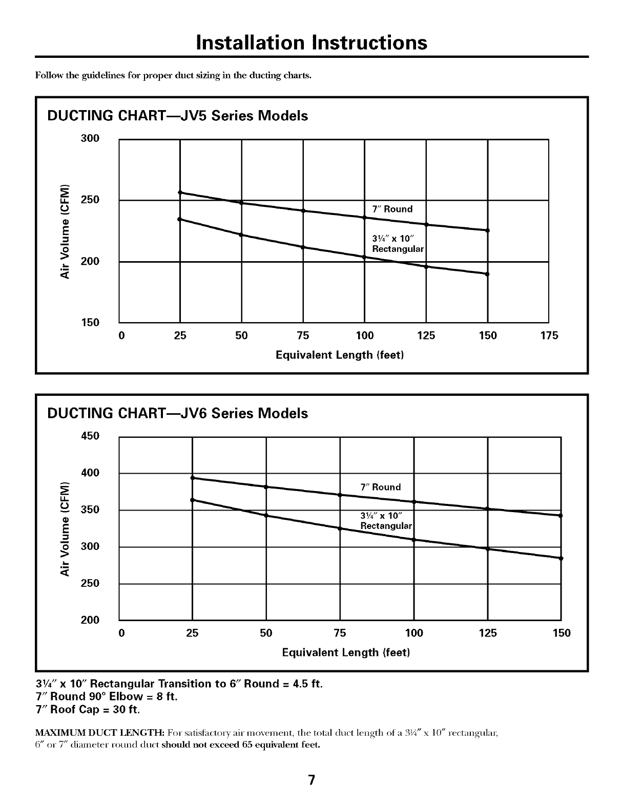
Follow the guidelines for proper duct sizing in the ducth_g charts.
DUCTING CHART_JV5 Series Models
3OO
u. 250
u
200
,m
<_
7" Round
31/4"x 10"
Rectangular
--.-...._.
150
25 50 75 100 125
Equivalent Length (feet)
150 175
DUCTING CHART_JV6 Series Models
45O
g.
0_
400
350
300
,m
<_ 250
200
0 25
7" Round
31/4" x 10"
50 75 100
Equivalent Length (feet)
125 150
31/4"x 10" Rectangular Transition to 6" Round = 4.5 ft.
7" Round 90 ° Elbow = 8 ft.
7" Roof Cap = 30 ft.
MAXIMUM DUCT LENGTH: For satisfactorx air movement the total duct length of a 3¼" x 10" rectangular;
6" or 7" diameter round duct should not exceed 65 equivalent feet.
7
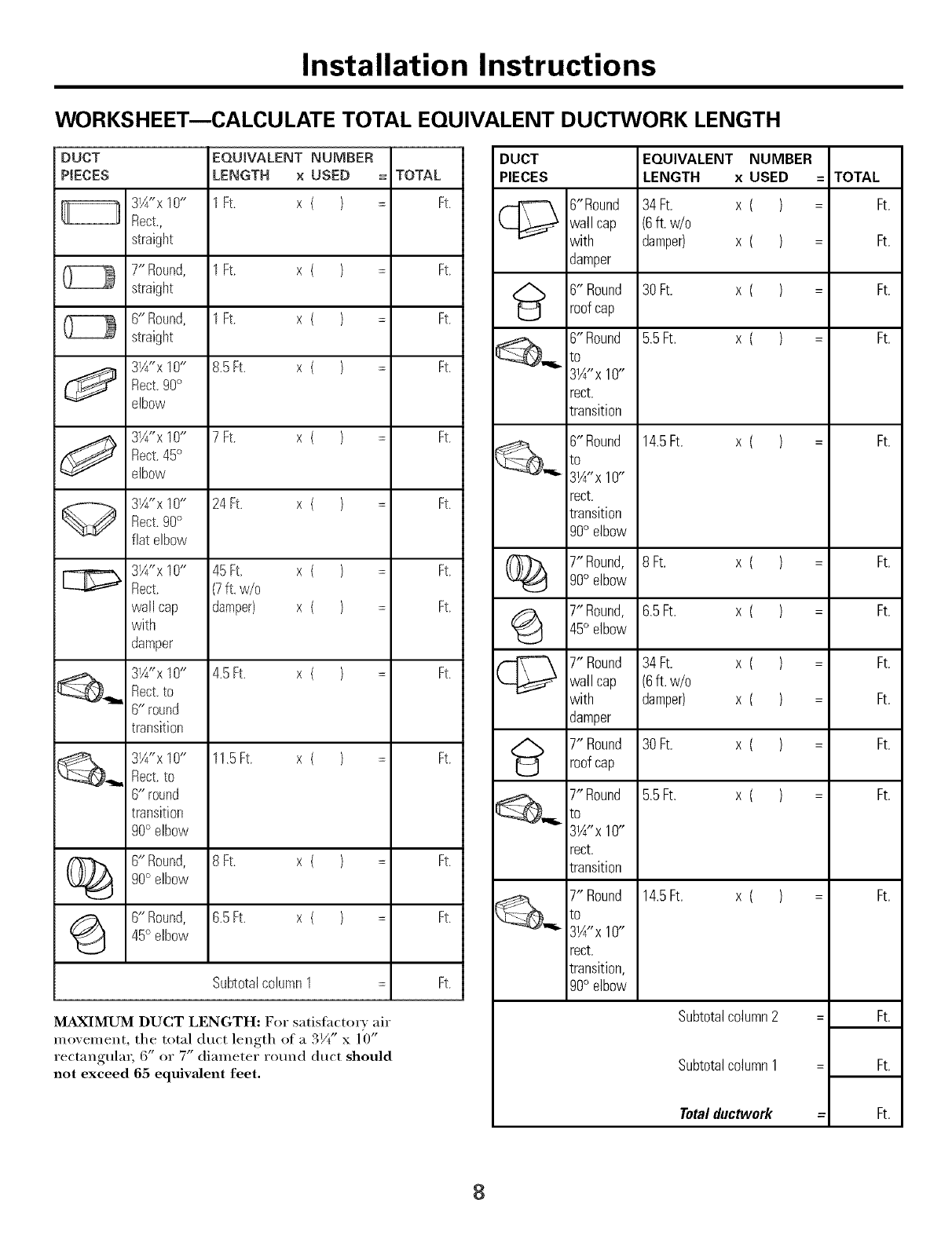
Installation Instructions
WORKSHEET--CALCULATE TOTAL EQUIVALENT DUCTWORK LENGTH
DUCT
PgECES
O
J
3W'x 10"
Rect.,
straight
7" Round,
straight
6" Round,
straight
3W'x 10"
Reck90°
elbow
3W'x 10"
Rect.45°
elbow
3W'x 10"
Rect.90°
flat elbow
3W'x 10"
Rect.
wall cap
with
damper
3W'x 10"
Rect.to
6" round
transition
3¼"x 10"
Rect.to
6" round
transition
90° elbow
EQUIVALENT NUMBER
LENGTH ×USED
lFt. x ( )
1Ft. x ( )
1Ft. x ( )
8.5Ft. x ( )
7Ft. x ( )
24Ft. x ( )
45Ft. x ( )
(7ft. w/o
damper) x ( )
4.5Ft. x ( )
11.5Ft. x ( )
(_ 6" Round, 8Ft. x ( )
90° elbow
(_ 6" Round, 6.5Ft. x ( )
45° elbow
SubtotalcolumnI =
= TOTAL
= Ft.
= Ft.
= Ft.
= Ft.
= Ft.
= Ft.
= Ft.
= Ft.
= Ft.
= Ft.
= Ft.
= Ft.
Ft.
MAXIMUM DUCT LENGTH: For satislhctor_ air
i]lo_,eillent, the total dt/ct length ot a 31/t" x 10"
rectangulm; 6" or 7" diameter round duct should
not exceed 65 equivalent feet.
DUCT
PIECES
6"Round
wall cap
with
damper
6" Round
roofcap
6" Round
to
3W'x 10"
rect.
transition
6" Round
to
3W'x 10"
rect.
transition
90° elbow
EQUIVALENT NUMBER
LENGTH x USED
34 Ft. x ( )
(6ft. w/o
damper) x ( )
30 Ft. x ( )
5.5Ft. x ( )
14.5Ft. x ( )
7"Round, 8Ft. x ( )90° elbow
7"Round, 6.5Ft. x ( )
45° elbow
7" Round 34 Ft. x ( )wall cap (6ft. w/o
with damper) x ( )
damper
7" Round 30 Ft. x ( )
roofcap
7" Round 5.5Ft. x ( )
3W'x 10"
rect.
transition
14.5R. x ( )
7" Round
to
3W'x 10"
rect.
transition,
90° elbow
Subtotalcolumn2
Subtotalcolumn1
Totalductwork
=TOTAL
Ft.
Ft.
Ft.
Ft.
Ft.
Ft.
Ft.
Ft.
Ft.
Ft.
Ft.
Ft.
= Ft.
= Ft.
=Ft.
8
Installation Instructions
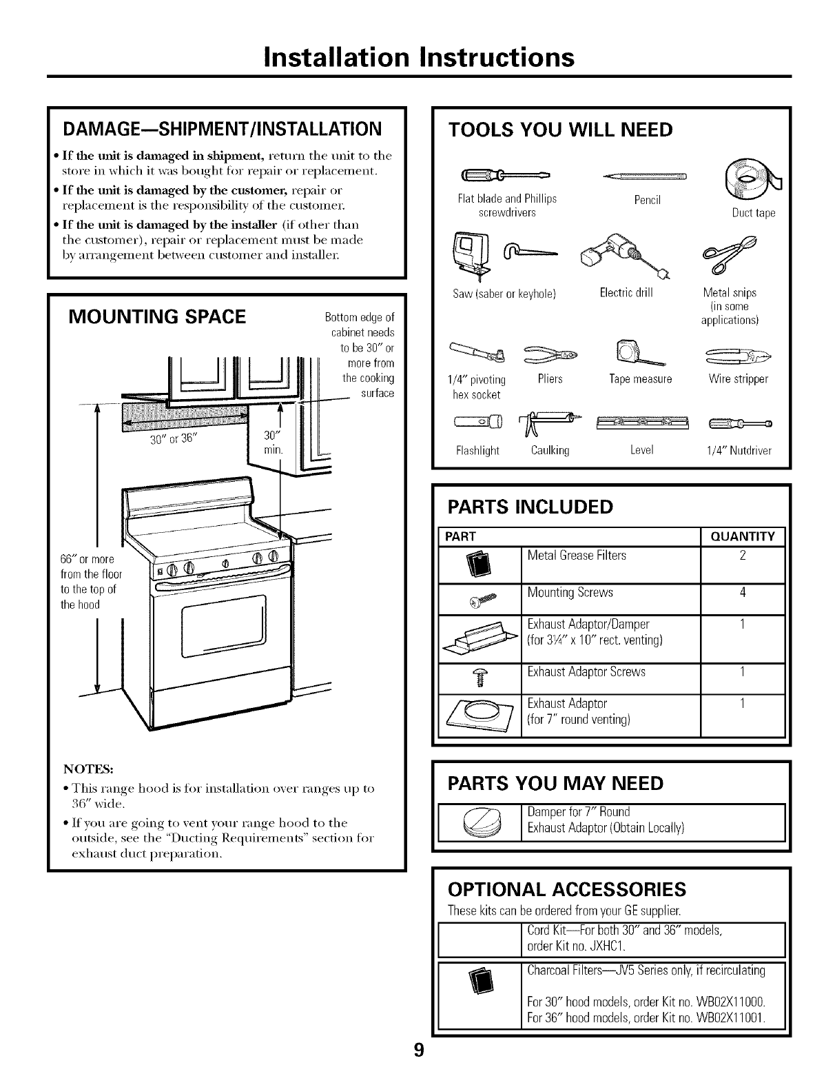
DAMAGE--SHIPMENT/INSTALLATION
•If the unit is da_naged in shipment, return the unit to the
store in which it was bought for repair or replacement.
• If the refit is dmnaged by the customer, repair or
replacement is the responsibility of the customer;
• If the unit is damaged by the installer (if other than
the customer), repair or replacement must be made
by arrangement between customer and instnlle_:
MOUNTING SPACE
.....;i.....
Bottomedgeof
cabinetneeds
to be 30" or
__j __J morefrom
the cooking
surface
the hood
NOTES:
• This range, hood is fin" installation oxer ram,es_, up to
•DWl(le.
• If YOU are going to vent your range hood to the
outside, see the "Ducting Requirements" section for
exhaust duct preparation.
TOOLS YOU WILL NEED
Flat blade and Phillips Pencil
screwdrivers Duct tape
Saw (saber or keyhole) Electric drill Metal snips
(in some
applications)
1/4" pivoting Pliers Tapemeasure Wire stripper
hex socket
Flashlight Caulking Level 1/4" Nutdriver
PARTS INCLUDED
PART QUANTITY
MetalGreaseFilters 2
MountingScrews 4
ExhaustAdaptor/Damper 1
(for3%" x 10" rect.venting)
ExhaustAdaptorScrews 1
ExhaustAdaptor 1
(for7" roundventing)
Damperfor 7" Round
ExhaustAdaptor(ObtainLocally) ,I
OPTIONAL ACCESSORIES
ThesekitscanbeorderedfromyourGEsupplier.
ICordKit--For both30" and36" models,
orderKit no.JXHC1.
CharcoalFilters--JV5Seriesonly,if recirculating
For30" hoodmodels,orderKit no.WB02X11000.
For36" hoodmodels,orderKit no.WB02X11001.
9
Installation Instructions
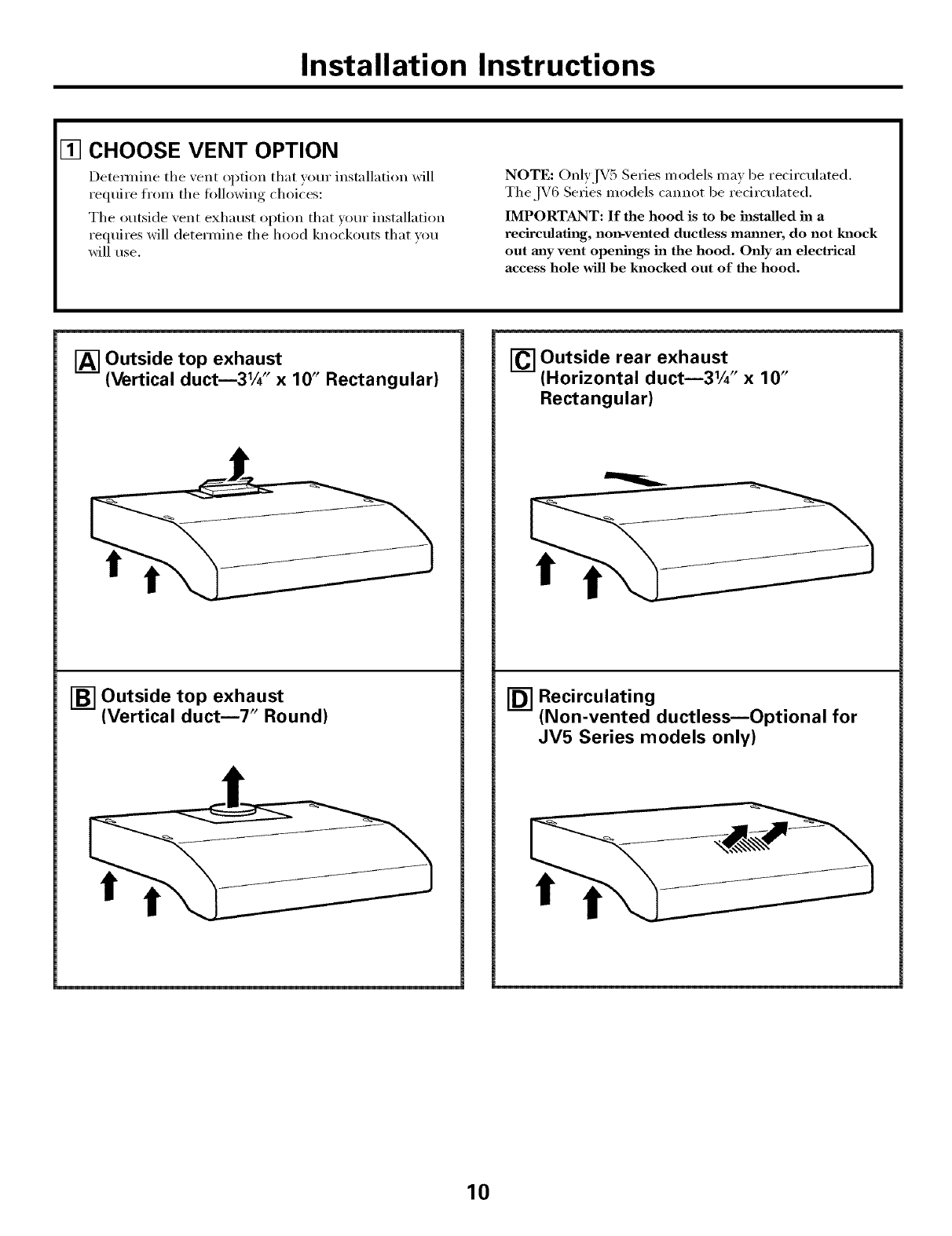
[] CHOOSE VENT OPTION
Detemfine the vent option that your installation will
require fl'om the t011owing choices:
The outside vent exhaust option that vour installation
requires will determine the hood knockouts that wm
will use.
NOTE: Only,IV5 Se_ies m odels may be recirculated.
The,IV6 Series models cannot be recirculated.
IMPORTANT: If the hood is to be installed in a
recirculating, non-vented ductless rammer, do not knock
out rely vent openings in the hood. Only an electrical
access hole will be knocked out of the hood.
[] Outside top exhaust 10"
(Vertical duct_3Vg' x Rectangular)
[_ Outside top exhaust
(Vertical duct_7" Round)
Outside rear exhaust 10"
(Horizontal duct_31A" x
Rectangular)
I-_ Recirculating
(Non-vented ductless_Optional for
JV5 Series models only)
10
Installation Instructions
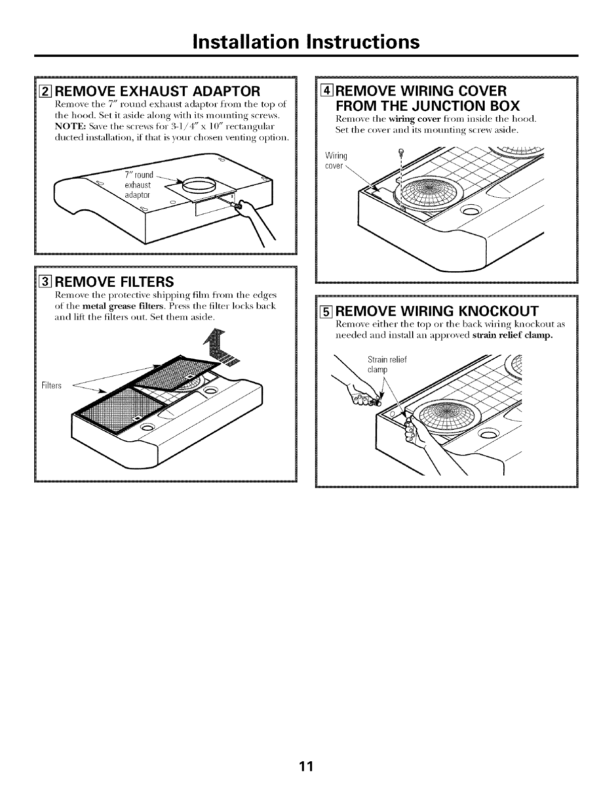
[] REMOVE EXHAUST ADAPTOR
Remove tile 7" round exhaust adaptor f'ron_ tile top ot
the hood. Set it aside ahmg with its mounting scre_vs.
NOTE: Save tile screws for 3-1/4" x 10" rectangular
ducted installation, if that is vom" chosen venting option.
[] REMOVE FILTERS
Remo_ e the protecti_ e .shiii__iw,_ fihn from the edges
of the metal grease filters. Press the filter locks back
and lift the filte_ ()/It. Set them aside.
Filters
I_REMOVE WIRING COVER
FROM THE JUNCTION BOX
Remo_e tile wiring cover fl'om inside tile hood.
Set tile cover and its mounting screw aside.
Wiring
cover
[] REMOVE WIRING KNOCKOUT
Remoxe either tile top or tile back wiring knockout as
needed and install an approxed strain refief clmnp.
Strainrelief
clamp
11
Installation Instructions
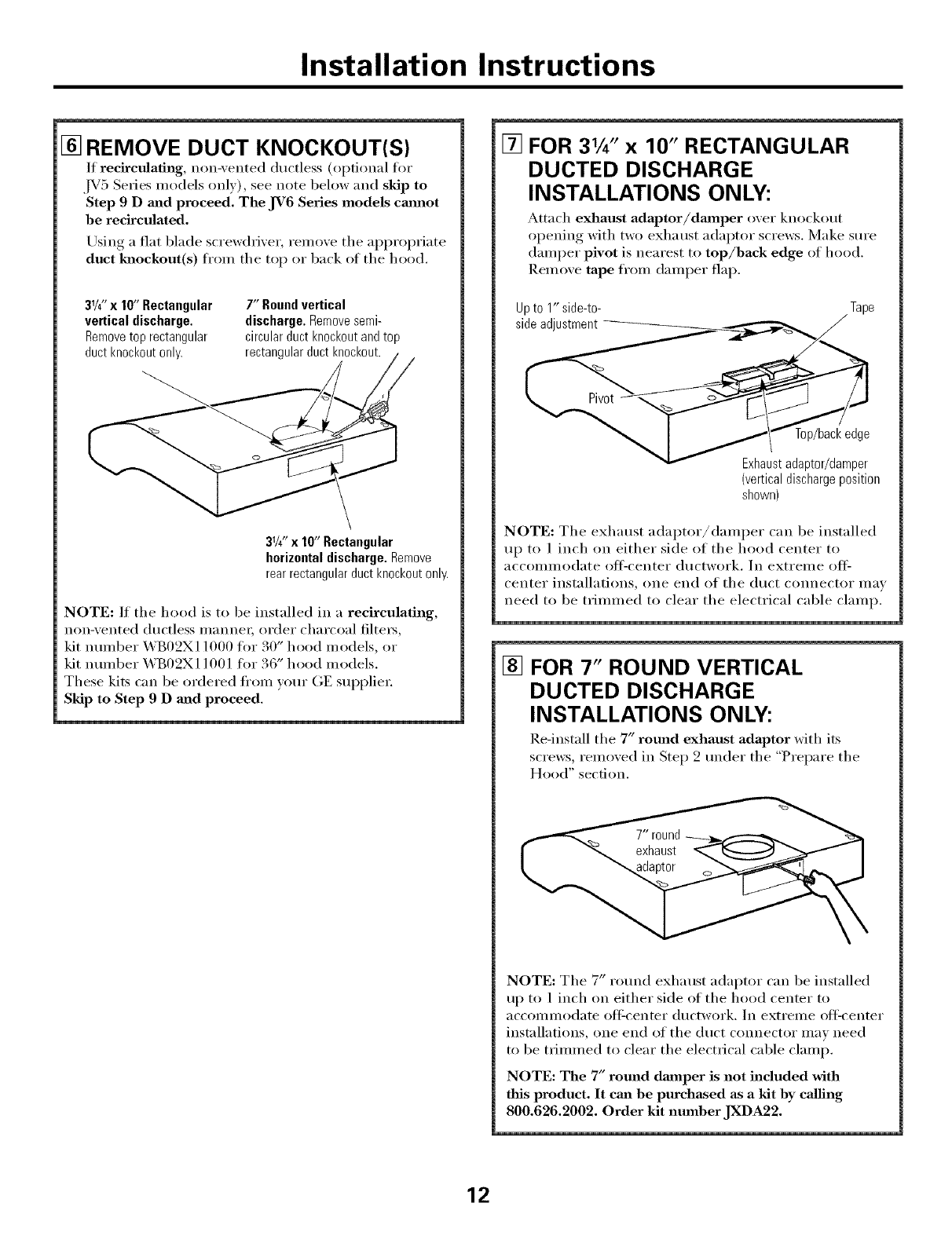
[] REMOVE DUCT KNOCKOUT(S)
If recirculating, non-\ented ductless (optional for
,IV5 Series models oulx), see uote below and skip to
Step 9 Dand proceed. The JV6 Series models cmmot
be recirculated.
Using a fiat blade screwdrixer, remove the appropriate
duct Mmckout(s) from the top or back of the hood.
31/4"x 10" Rectangular 7" Round vertical
vertical discharge• discharge. Remove semi-
Remove top rectangular circular duct knockout and top
duct knockout only. rectangular duct knockout. ,
31/4''x 10" Rectangular
horizontal discharge. Remove
rear rectangular duct knockout only.
NOTE: If the hood is to be installed in a recirculating,
non-xented ductless manne_; order charcoal filte_,
• _ 0 _ • 3"
kit nmnber _._B 2X11000 for. 0 hood models, or
kit nmnber _ B()2X ] ] O0 ] for.3""o hood models.
These kits can be ordered from yore" (;E supplie_:
Skip to Step 9 D and proceed.
[] FOR 31/4''x 10" RECTANGULAR
DUCTED DISCHARGE
INSTALLATIONS ONLY:
Attach exhaust adaptor/dmnper over knockout
opening with two exha tlSt adaptor screws. Make sure
damper pivot is nearest to top/back edge of hood.
Remove tape fl'om damper flap.
Upto 1" side-to-
sideadjustment
Top/back edge
Exhaustadaptor/damper
(verticaldischargeposition
shown)
NOTE: The exhaust adaptor/damper can be installed
up to ] inch on either side of the hood center to
acc()Ullllodate off:center ductwork. ]U extreine off _
center installations, one end of the duct connector may
need to be trimmed to clear the electrical cable clamp.
[] FOR 7" ROUND VERTICAL
DUCTED DISCHARGE
INSTALLATIONS ONLY:
Re-install the 7" round exhaust adaptor with its
screws, remoxed in Step 2 trader the "Prepare the
Hood" section.
NOTE: The 7" rotmd exhaust adaptor can be installed
up to 1 inch on either side of the hood center to
accommodate off:center ductwork. In extreme off:center
installations, one end of the duct c(mnector may need
to be trimmed to clear the electrical cable clamp.
NOTE: The 7" round damper is not included with
this product, It can be purchased as a kit by calling
800.626.2002. Order kit number JXDA22.
12
Installation Instructions
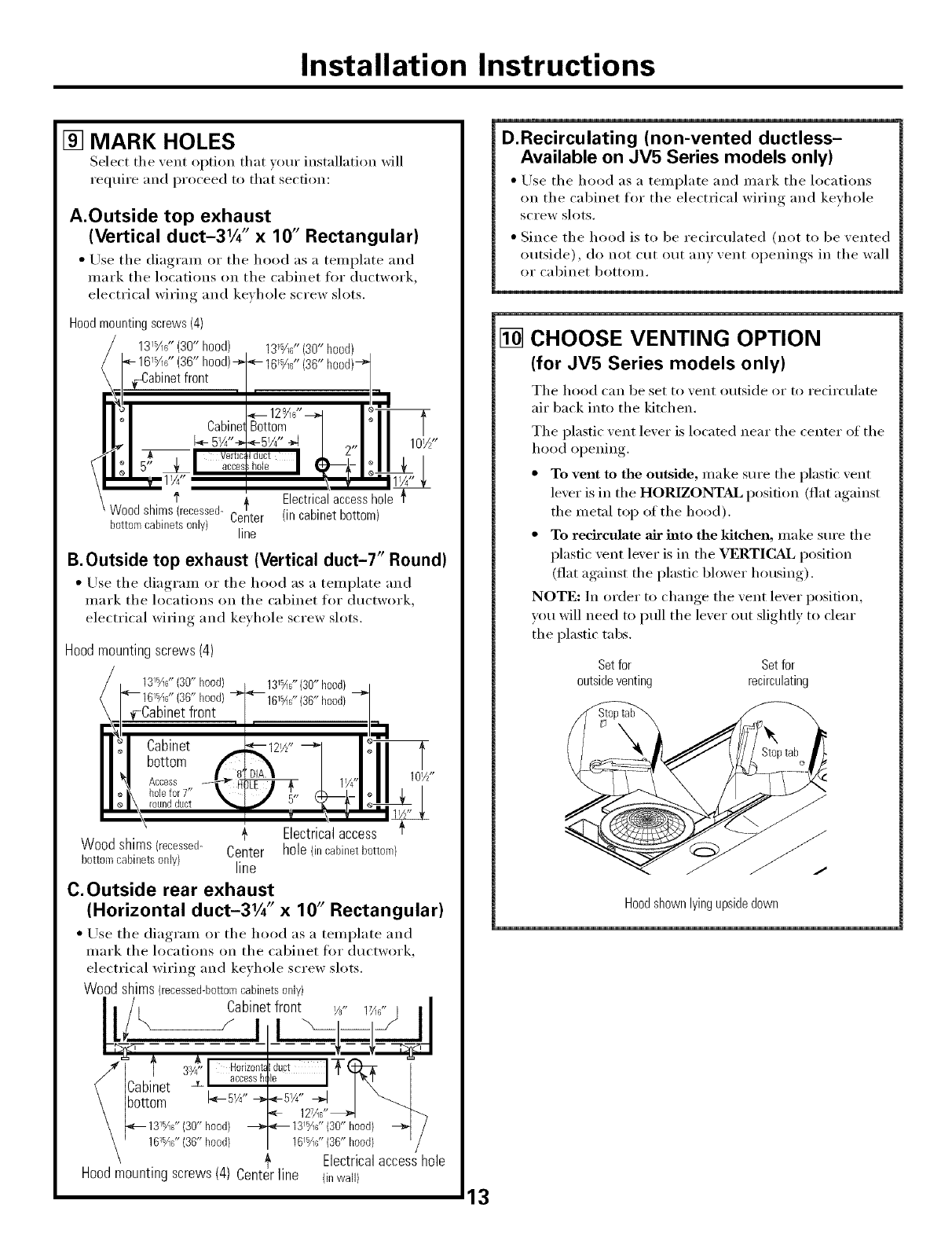
[] MARK HOLES
Select the _ent option that _our installation will
require and proceed to that section:
A.Outside top exhaust
(Vertical duct-31/4" x 10" Rectangular)
• Use the (liagram or the hood as a template and
mark the locations (m the cabinet fin" ductwork,
electrical wiring and keyhole screw slots.
Hood mounting screws (4)
131_6" (30" hood)
(36" 13_s/U'(30" hood)
f Electricalaccesshole
Woodshims(recessed- '}
Center (incabinetbottom)
bottomcabinetsonly) line
B.Outside top exhaust (Vertical duct-T' Round)
• Use the diagram or the hood as a template and
mark the locations on the cabinet for ductwork,
electrical wiring and keyhole screw slots.
Hoodmountingscrews(4)
131_6" (30" hood) 131_6" (30" hood)
hood)
101//'
_- Electrical access
Wood shims (recessed- Center hole (in cabinetbottom}
bortom cabinets only) line
C.Outside rear exhaust
(Horizontal duct-31/4" x 10" Rectangular)
• Use the diagram or the hood as a template and
mark the locations on the cabinet for ductwork,
electrical wiring and keyhole screw slots.
Wood shims (recessed-bottomcabinetsonly)
f 3V43_- Horizonb Iduct T
loccossh,o I
(Eabinet , I \ I
\ [bottom 1_-5W' _"&_-51/4,, --a_ I _l
\i _ 127A6"_ _''7
15 _ _ 15
\ p_--13_A6"(30"hood) 13'A6"(30"hood) _-_ /
\ -- 161_fi6"(36"hood} 161_16"(36"hood) ' r
Electrical access hole
Hood mounting screws (4) (inwall)
D.Recirculating (non-vented ductless-
Available on JV5 Series models only)
• Use the hood as a template and mark the locations
on the cabinet for the electrical wiring and keyhole
screw slots.
• Since the hood is to be recirculated (not to be vented
outside), do not cut out am xent oi)enings, in the wall
or cabinet bottom.
[] CHOOSE VENTING OPTION
(for JV5 Series models only)
The hood can be set to _ent outside or to recirculate
air back into the kitchen.
The plastic xent lexer is located near the center of the
hood opening.
• To vent to the outside, make sm'e the plastic xent
lexer is in the HORIZONTAL position (flat against
the metal top of the hood).
• To redrculate air into the kitchen, make sure the
plastic xent lever is in the VERTICAL position
(fiat against the plastic blower housing).
NOTE: In order to change the xent lexer position,
you will need to pull the lever out slightly to clear
the plastic tabs.
Setfor Setfor
outsideventing recirculating
Hoodshownlyingupsidedown
mnstaJiation mnstructions
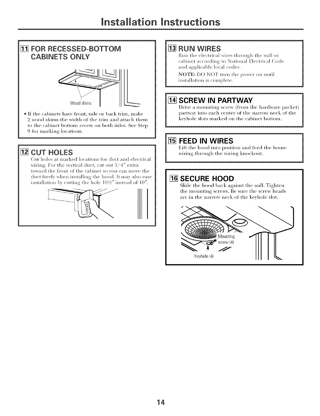
[] FOR RECESSED-BOTTOM
CABINETS ONLY
• If the cabinets haxe front, side or back trim, make
2 wood shims the width of the trim and attach them
to the cabinet bottom recess on both sides. See Step
9 for marking locations.
[] CUT HOLES
(;ut holes at marked locatio]_s for (]u_ amid electrical
wiriwg, For the vertical duct. cut out :/4 extra
toward the {foist of the cab]]_et so _olt Gm move the
duct freely w]]em_ im_sta]liN_g t]_e hood. It ma', also ease
imlsta]]atio]) b} cuttimlg tile hole 105" imlstead of 10".
[] RUN WIRES
Rm_ die electrical wires d_rough d_e wall or
c"abim_et "accordim_g to Nation,a] E]ectrica] Code
amid applicable local codes.
NOTE: DO NOT mrl_ d_e power (m m_ti]
im_sta]]ati(m is _ omp]ete.
[] SCREW IN PARTWAY
Drixe a mom]ting screw (from the hardware packet)
partwa) into each center of the narrow neck of the
keyhole slots marked on the cabinet bottom.
[] FEED IN WIRES
i,ift the hood into position and feed the house
wiring throw,h_ the wiriw,_ knockout.
[] SECURE HOOD
Slide the hood back against the wall, Tighten
the mounting screws. Be sure the screw heads
are in the narrow neck of the keyhole slot.
Mounting
Keyhole (4)
14
Installation Instructions
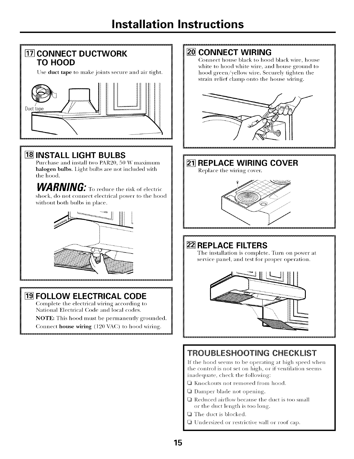
[] CONNECT DUCTWORK
TO HOOD
Use duct tape to make joints secure and air tight.
[] INSTALL LIGHT BULBS
Purchase and install two PAR20, 50 _ nmxinmm
halogen bulbs. I,ight bulbs are not included with
the hood.
WARNING:T.,ed.cethe, isk.,e,e,t, i,'
shock, do not connect electrical power to the hood
without both bulbs in place.
[] FOLLOW ELECTRICAL CODE
Complete the electrical wiring according to
National Electrical Code and local codes.
NOTE: This hood must be pemmnently grmmded.
Connect house wiring ( 120 VAC) to hood wiring.
[] CONNECT WIRING
Connect house black to hood black wire, house
white to hood white wire, and house grotmd to
hood green/)e,low wire. Securely tighten the
strain relief clamp onto the house wiring
[] REPLACE WIRING COVER
Replace the wiring co_er.
[] REPLACE FILTERS
The installation is complete. Turn on power at
service pane,, and test for proper operation.
TROUBLESHOOTING CHECKLIST
I_ the hood seems to be operatim_g at high speed whem_
the com_tro] is m_ot set on high, or if yen ti]a ti om_ seem s
im_adeql_ate, check the foIIowim_g:
U_ Knockouts m_ot removed from hood.
Damper blade m_t opem_im_g.
Red,Iced air{low because the duct is too sinai]
or the dh_ct length is too long.
U_ The dutt is blocked.
[ Im_dersized or restrictive _r_]] ()_" _'()of C:_[).
15
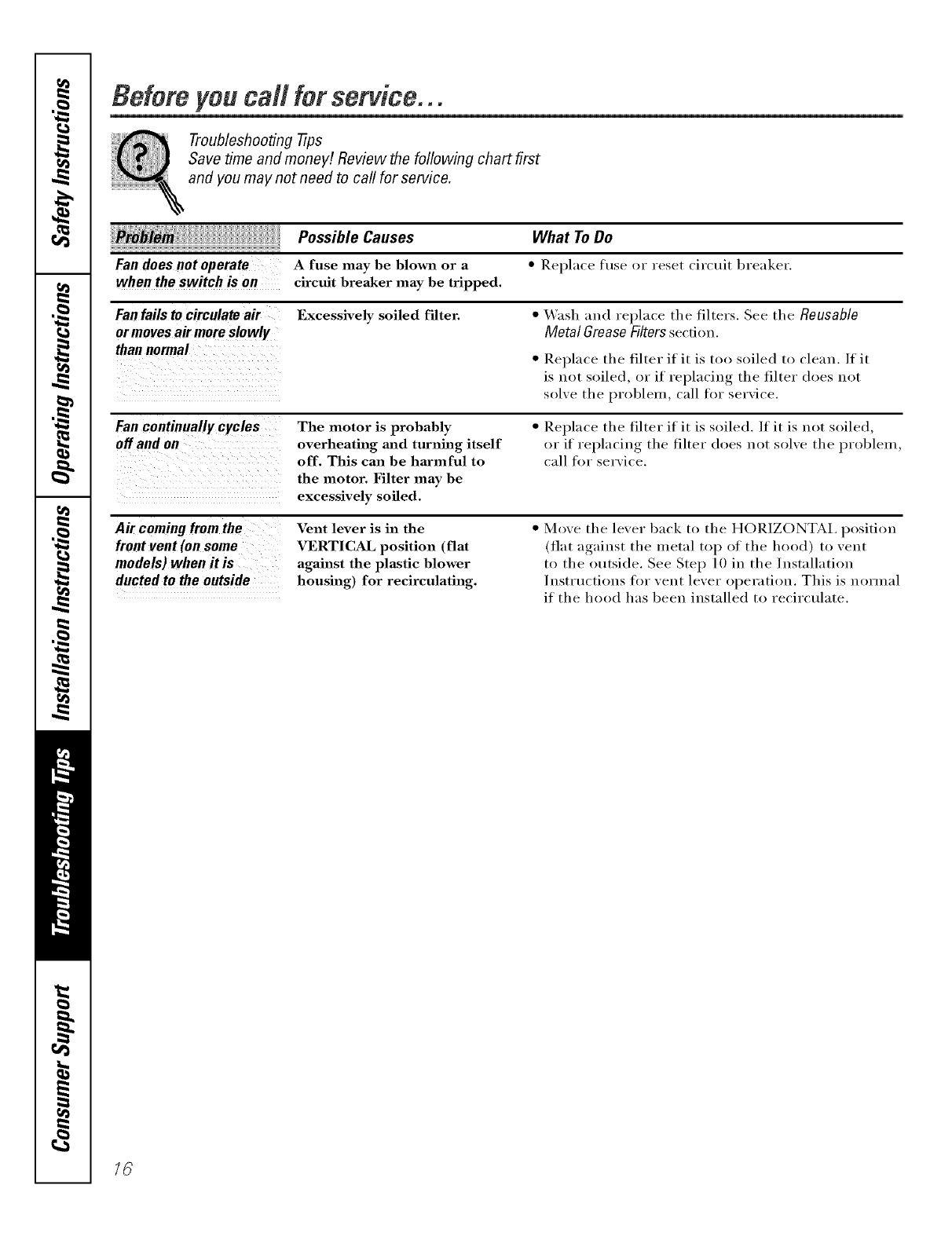
Befem you call for service...
Troubleshooting -tips
Save time and money! Review the following chart first
and you may not need to call for service.
Possible Causes What ToDo
Fan does not operate Afuse may be blown or a • Replace tuse or reset circuit breaker.
when the switch is on circuit breaker may be tripped.
Fanfailsto circulateair
ormovesair moreslowly
thannormal
Excessively soiled filter. "_,_ashand replace the filters. See the Reusable
Metal GreaseFilterssection.
Replace the filter if it is too soiled to clean. If it
is not soiled, or if replacing the filter does not
solxe the problem, call for service.
Fancontinuallycycles
off and on The motor is probably
overheating mid turning itself
off. This can be harmful to
the motor. Filter may be
excessively soiled.
• Replace the filter if it is soiled. If it is not soiled,
or if replacing the filter does not solxe the problem,
call for serxice.
A# comingfromthe
front vent(onsome
models)when it is
ductedto the outside
Vent lever is in the
VERTICAL position (flat
against the plastic blower
housing) for recirculating.
• Move the lever back to the HORIZONTAI, position
(fiat against the metal top of the hood) to vent
to the outside. See Step 10 in the Installation
Instructions fi_r vent lever operation. This is normal
if the hood has been installed to recirculate.
16
Notes,
_t
_#_
_L
I
w
m
17
Q}
m
__
m
I
Netes.
18
GERangeHood Warranty.
All warranty service provided by our Factory Service Centers,
or an authorized Customer Care®technician. Toschedule service,
on-line, 24 hours a day, visit us at GEAppliances.com, or call
800.GE.CARES(800.432.2737).
Staple your receipt here.
Proof of the original purchase
date is needed to obtain service
under the warrant_
One Year
Fromthe date of the
origina!purchase
GEWill Replace:
Anypattof the range hood which fifils due to a defect in materials or _xn'kmanship,
During this full one-year warranty, GE will also provide, free of charge, all labor and
in-home service to replace the defective part,
Service trips to your home to teach you how to use
the product.
Improper installation, delivery or maintenance.
Failure of the product if it is abused, misused, or
used for other thm_ the intended purpose or used
commercially.
Replacement of house fuses or resetting of circuit
breakers.
Dmnage to the product caused by accident, fire, floods
or acts of God.
h_cidentaJ or consequential dmuage caused by possible
defects with this applimlce.
Dmuage caused after delivery.
This warranty is extended to the original purchaser and any succeeding owner for products purchased for home
use within the USA. In Alaska, the warranty excludes the cost of shipping or service calls to your home.
Some states do not allow the exclusion or limitation of incidental or consequential damages. This warranty gives
you specific legal rights, and you may also have other rights which vary from state to state. To know what your
legal rights are, consult your local or state consumer affairs office or your state's Attorney General
Warrantor. General Electric Company.Louisville,KY 40225
19

ConsumerSupport.
GEAppliancesWebsite www.GEAppliances.com
Have a question or need assist;race with your appliance? Try the (;E Al)pliances Website 24 hom_ a (la);
any day of the year'. For greater convenience and faster se_Mce, you can now download Owner's Manuals,
order parts, catalogs, or even schedule service on4ine. You can also "_&skOur Team of Experts .....
your questions, and so much more...
ScheduleService www.GEAppliances.com
Expert (;E repair service is onlx one step away from xour (loo_; Get on-line and schedule your service at
,_our conxenience 24 hou_ any (lm of the year! Or call 800.(;E.(:ARES (800.432.2737) during n{mnal
business hou_.
RealLifeDesignStudio www.GEAppliances.com
GE SUl_ports the Universal Design concel_t--products, services and environments that can be used by
people ot all ages, sizes and capabilities. We recognize the need to design fin" a wide range of physical and
mental abilities and impaimmnts. For details of GE's Universal Design applications, including kitchen
design ideas for people with disabilities, check out otlr Websim today. For the hearing impaired, please call
800.TDD.GEAC (800.833.4322).
Extended Warranties www.GEAppliances.com
Purchase a (;E extended warrant_ and learn about special discounts that are axailable while _our warrant_
is still in effect. You can purchase it on-line anytiine, or call 800.626.2224 during nomml business l_otu_.
(;E Consumer Home Serxices will still be there after }our warranty expires.
PartsandAccessories www.GEAppliances.com
Individuals qualified to service their own appliances can have parts or accessories sent directly to their
homes (VISA, MasterCard and Discover cards are accepted). Order on-line toda 5 24 hou_ every day or
by phone at 800.626.2002 during nomml business hou_.
Instructions contained in this manual cover procedures to be performed by any user. Other servicing generally
should be referred to qualified service personnel Caution must be exercised, since improper servicing may cause
unsafe operation.
ContactUs www.GEAppliances.com
If you are not satisfied with the service you receive ti'om GE, contact us on our _.Vebsite with all the details
including your phone ntlI/lbeI; or write to: General Manage_; Customer Relations
GE Appliances, Appliance Park
I,ouisville, KY 40225
RegisterYourAppliance www.GEAppliances.com
Register your new applim_ce on-lhle---at your convenience! Timely product registration will allow fin.
enhanced communication and prompt service under the terms ofxour warranty should the need arise.
You may also mail in the pre-printed registration card included in the I)ackin°_ material.
20 Printed in Italy
