GE Dishwasher Manual L0504084
GSD2200G05WW GSD2200G05WW GE DISHWASHER - Manuals and Guides L0504084 View the owners manual for your GE DISHWASHER #GSD2200G05WW. Home:Kitchen Appliance Parts:GE Parts:GE DISHWASHER Manual
User Manual: GE GE Dishwasher Manual GE Dishwasher Owner's Manual, GE Dishwasher installation guides
Open the PDF directly: View PDF ![]() .
.
Page Count: 8
If you have a question concerning the installation of this
product, call the GEAnswer Center _'Consumer Information
Service at 800.626.2000,24 hours a day, 7days a week.
If you received a damaged dishwasher,
you should immediately contact your
dealer or builder.
Installation of this dishwasher requires basic mechanical and
electrical skills. Properinstallation is the responsibilityof the
installer.Productfailure dueto improperinstallation is not
coveredunderthe GEApplianceWarranty. See the back cover
of the Owners Manual for warranty information.
The dishwasher MUST be installed to allow for future removal
from the enclosure if service is required.
[] Two Phillips head countertop mounting screws taped to dishwasher
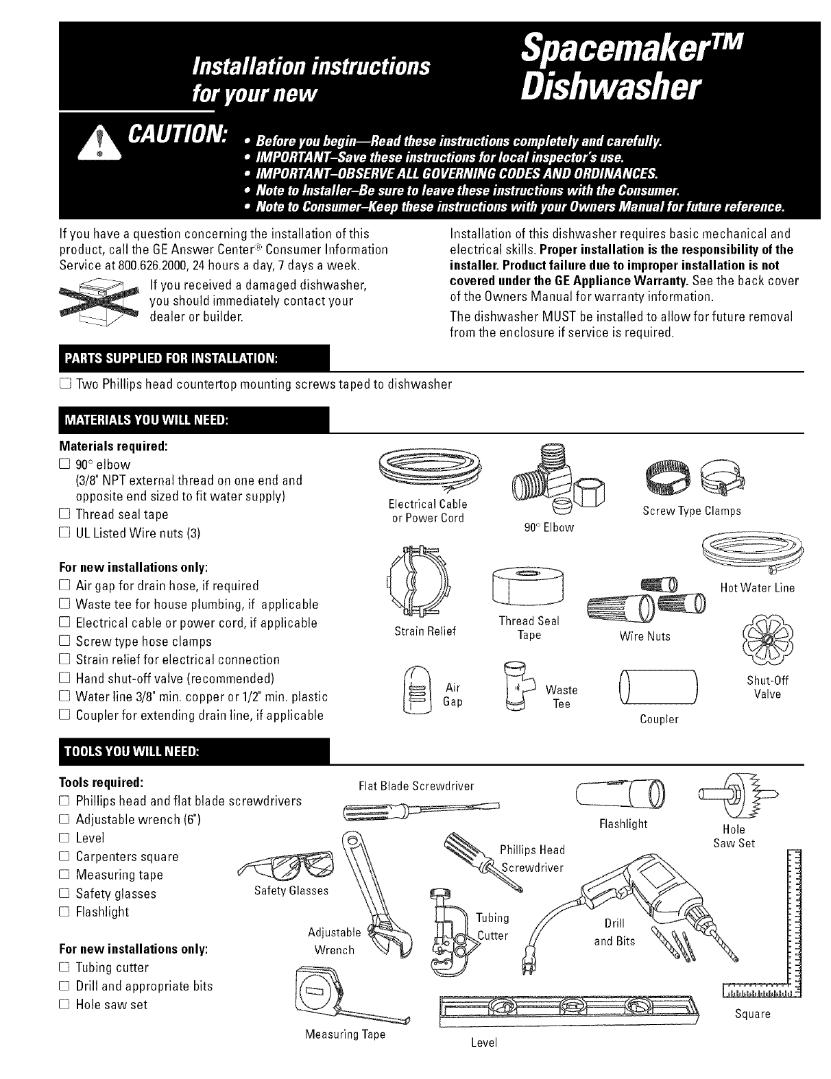
Materials required:
[] 90° elbow
(3/8"NPTexternal thread on one end and
opposite end sizedto fit water supply)
[] Thread seal tape
[] UL Listed Wire nuts (3)
Fornew installationsonly:
[] Air gap for drain hose, if required
[] Waste tee for house plumbing, if applicable
[] Electrical cable or power cord, if applicable
[] Screwtype hose clamps
[] Strain relief for electrical connection
[] Hand shut-off valve (recommended)
[] Water line 3/8" rain. copper or 1/2"rain. plastic
[] Coupler for extending drain line, if applicable
Electrical Cable
or Power Cord 90° Elbow
Screw Type Clamps
ThreadSeal
StrainRelief Tape Wire Nuts
[L_ Air6up _Waste 0Tee
Coupler
HotWater Line
Shut-Off
Valve
Tools required:
[] Phillips head and flat blade screwdrivers
[] Adjustable wrench (6")
[] Level
[] Carpenters square
[] Measuring tape
[] Safety glasses
[] Flashlight
Fornew installations only:
[] Tubing cutter
[] Drill and appropriate bits
[] Hole saw set
Safety Blasses
Adjustable _-_
Wrench \N
Measuring Tape
FlatBladeScrewdriver (E_I _CC>
Flashlight Hole
_. PhillipsHead
SawSet
wdri_
_Tubing // Drill __
_Cutter _ andBits _-'_
Level
Square
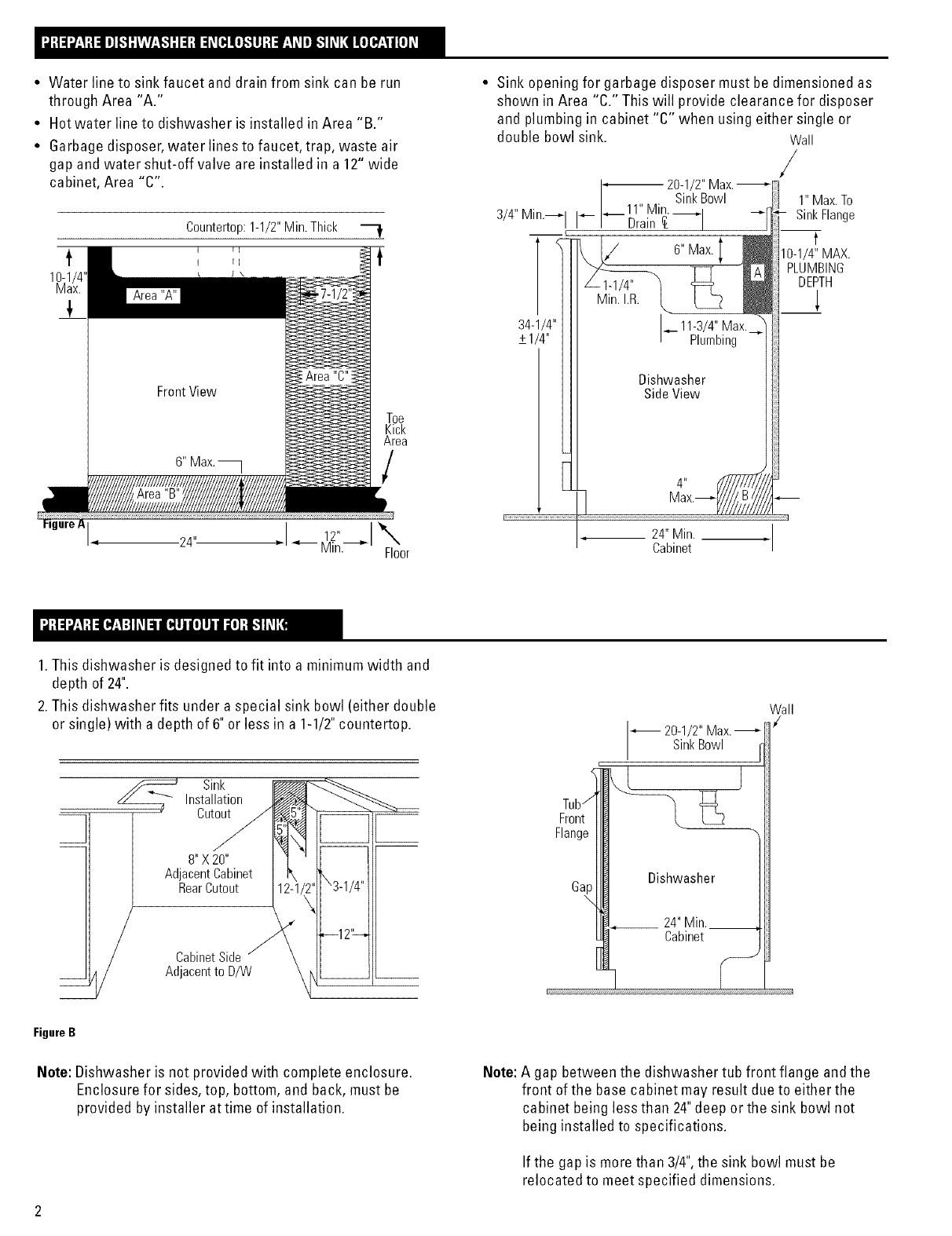
•Water line to sink faucet and drain from sink can be run
through Area "A."
• Hot water line to dishwasher is installed in Area "B."
• Garbage disposer, water lines to faucet, trap, waste air
gap and water shut-off valve are installed in a 12" wide
cabinet, Area "C".
t
10-1/4"
Max.
Countertop:1-1/2"Min.Thick
Toe
Kick
Area
/
I. 24" X
Floor
• Sink opening for garbage disposer must be dimensioned as
shown in Area "C." This will provide clearance for disposer
and plumbing in cabinet "C" when using either single or
double bowl sink. Wall
20-1
SinkBowl
3/4"Min._ I _ ._11" Min.
Brain
_2. I/ 6"Max.
34-1/4"
+1/4"
J
A
L11-3/4" Max.
Plumbing
Dishwasher
SideView
............................................................................ l
24"Min. ÷
Cabinet
/
1"Max.To
SinkFlange
fMAX.
PLUMBING
DEPTH
1. This dishwasher is designed to fit into a minimum width and
depth of 24".
2. This dishwasher fits under a special sink bowl (either double
or single) with a depth of 6" or less in a 1-1/2"countertop.
Sink
Installation
Cutout
a/
H/Cabinet Side "
_h/ Adjacent to D/W
Wall
/
20-1/2" Max. -_--
, I SinkBowl q
E.... _
FigureB
Note: Dishwasher is not provided with complete enclosure.
Enclosure for sides, top, bottom, and back, must be
provided by installer at time of installation.
Note: A gap between the dishwasher tub front flange andthe
front of the base cabinet may result due to either the
cabinet being less than 24"deep orthe sink bowl not
being installed to specifications.
If the gap is more than 3/4",the sink bowl must be
relocated to meet specified dimensions.
DRAIN REQUIREMENTS
•Follow local codes and ordinances.
•Dishwasher drain hose must not exceed 10feet in length for
proper drainage.
• Dishwasher must be connected to waste line with an air gap
(not supplied) or 32"minimum, high drain loop depending on
local codes and ordinances to prevent back flow into the
dishwasher.
• Air gap must be used if waste tee or disposer connection is
less than 18inches above floor to prevent siphoning.
DRAIN PREPARATION
The type of drain installation depends on answers to the
following questions:
[] Dolocal codes or ordinances require an air gap?
[]Will waste tee or disposer connection be less than 18"above
floor?
[]Will installation have a drain loop less than 32"above floor?
If the answer to ANY of the 3 questions above is YES,Method 1
MUST he used. Otherwise either Method 1 or Method 2 may be
used. Figure Cor Figure D.
AnairgapMUSTBEUSEDif thedrainhoseis connectedto wastetee or
disposerlowerthan 18"abovethefloor level.Failureto providetheproper
drainconnectionheightwith airgapor32"minimum,highdrainloopwill
resultin improperdrainingof thedishwasherwhichmaycausedamage.
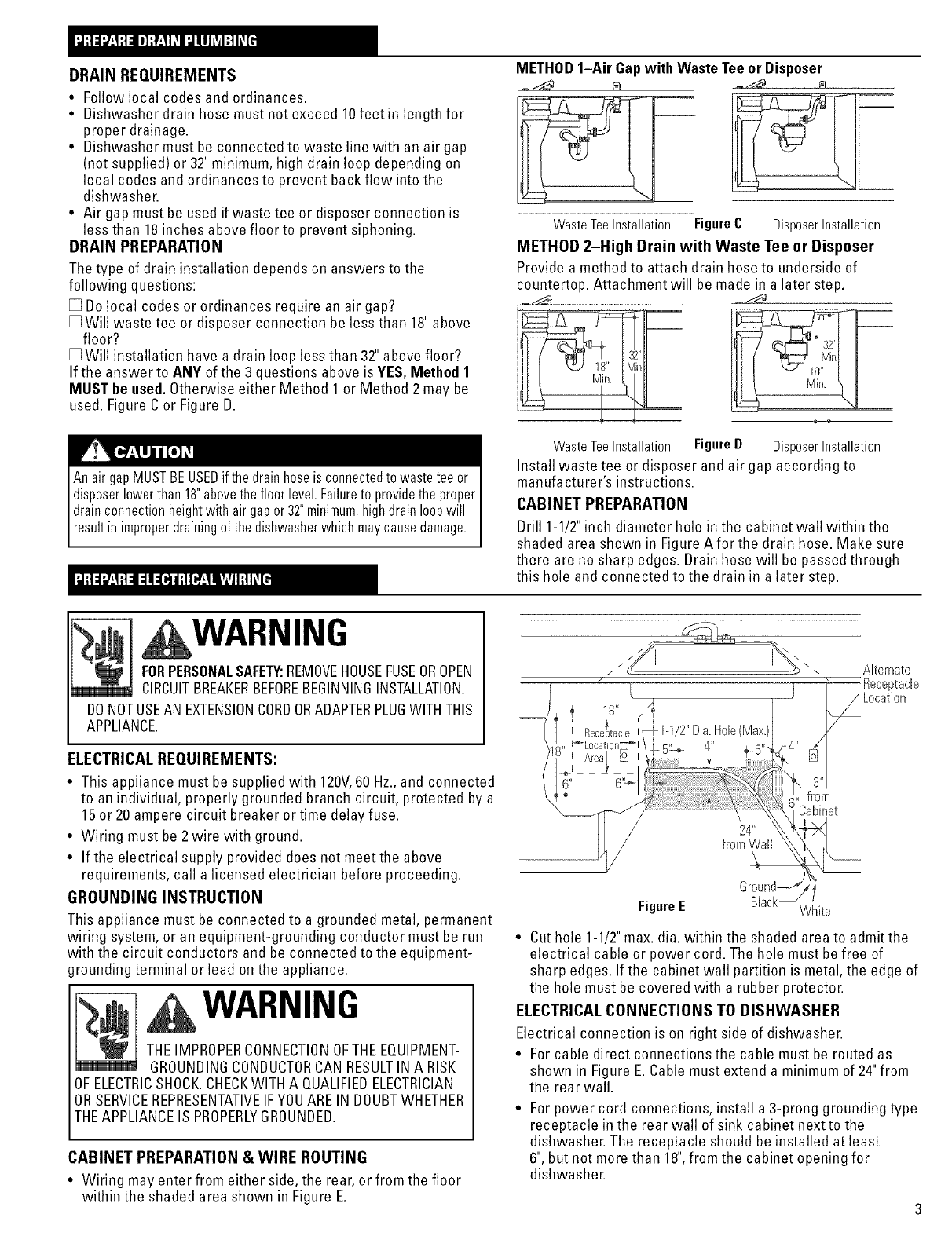
METHOD1-Air Gap with Waste Tee or Disposer
Waste Tee Installation Figure C Disposer Installation
METHOD 2-High Drain with Waste Tee or Disposer
Provide a method to attach drain hose to underside of
countertop. Attachment will be made in a later step.
I8"
!-
WasteTeeInstallation FigureD DisposerInstallation
Install waste tee or disposer and air gap according to
manufacturer's instructions.
CABINET PREPARATION
Drill 1-1/2"inch diameter hole in the cabinet wall within the
shaded area shown in FigureAfor the drain hose. Make sure
there are no sharp edges. Drain hose will be passedthrough
this hole and connected to the drain in a later step.
WARNING
FORPERSONALSAFETY:REMOVEHOUSEFUSEOROPEN
CIRCUITBREAKERBEFOREBEGINNINGINSTALLATION.
DONOTUSEAN EXTENSIONCORDORADAPTERPLUGWITHTHIS
APPLIANCE.
ELECTRICALREQUIREMENTS:
• This appliance must be supplied with 120V,60 Hz.,and connected
to an individual, properly grounded branch circuit, protected by a
15or 20ampere circuit breaker or time delay fuse.
• Wiring must be 2 wire with ground.
• If the electrical supply provided does not meet the above
requirements, call a licensed electrician before proceeding.
GROUNDING INSTRUCTION
This appliance must be connected to a grounded metal, permanent
wiring system, or an equipment-grounding conductor must be run
with the circuit conductors and be connected to the equipment-
grounding terminal or lead on the appliance.
WARNING
THEIMPROPERCONNECTIONOFTHEEQUIPMENT-
GROUNDINGCONDUCTORCANRESULTIN A RISK
OFELECTRICSHOCK.CHEOKWITHA QUALIFIEDELECTRICIAN
ORSERVICEREPRESENTATIVEIFYOUAREIN DOUBTWHETHER
THEAPPLIANCEIS PROPERLYGROUNDED.
CABINET PREPARATION & WIRE ROUTING
• Wiring may enter from either side, the rear, or from the floor
within the shaded area shown in Figure E.
/ / "f_ ...... .\ \
Receptacle
l/L°cati°n
-- ___ .... 1/
_,, I_-Location_L__ 4" _Lq",.LF4" ,_£ I
I Area|
-f
Cabinet
FigureE White
• Cut hole 1-1/2"max. dia. within the shaded area to admit the
electrical cable or power cord. The hole must be free of
sharp edges. If the cabinet wall partition is metal, the edge of
the hole must be covered with a rubber protector.
ELECTRICALCONNECTIONS TO DISHWASHER
Electrical connection is on right side of dishwashen
• For cable direct connections the cable must be routed as
shown in Figure E.Cable must extend a minimum of 24"from
the rear wall.
• For power cord connections, install a 3-prong grounding type
receptacle in the rear wall of sink cabinet next to the
dishwasher. The receptacle should be installed at least
6",but not more than 18",from the cabinet opening for
dishwasher.
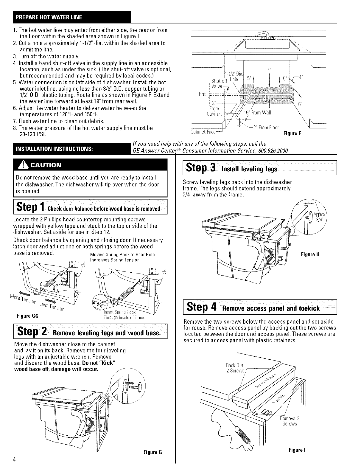
1.Thehotwaterlinemayenterfromeitherside,therearorfrom
thefloorwithintheshadedareashowninFigureE
2.Cutaholeapproximately1-1/2"dia.withintheshadedareato
admittheline.
3.Turnoffthewatersupply.
4.Installahandshut-offvalveinthesupplylineinanaccessible
location,suchasunderthesink.(Theshut-offvalveisoptional,
butrecommendedandmayberequiredbylocalcodes.)
5.Waterconnectionisonleftsideofdishwasher.Installthehot
waterinletline,usingnolessthan3/8"O.B.coppertubingor
1/2"O.B.plastictubing.RoutelineasshowninFigureEExtend
thewaterlineforwardatleast19"fromrearwall.
6.Adjustthewaterheatertodeliverwaterbetweenthe
temperaturesof120°Fand150°E
7.Flushwaterlinetocleanoutdebris.
8.Thewaterpressureofthehotwatersupplylinemustbe
20-120PSI.
If you need help with
GEAnswer Center<_'
Do not removethe wood base until you are readyto install
the dishwasher. The dishwasher will tip over when the door
is opened.
Step1 Checkdo0rbalancebeforewo0dbaseis removed
Locatethe 2 Phillips head countertop mounting screws
wrapped with yellow tape and stuck to the top or side of the
dishwasher. Set aside for use in Step 12.
Check door balance by opening and closing door. If necessary
latch door and adjust one or both springs before the wood
base is removed. Moving Spring Hookto Rear Hole
Increases Spring Tension.
_er/qol q
ior/ nsert Spring
Figure GG ThroughInsideof Frame
Step2 Remove leVeling legs andwood
Move the dishwasher close to the cabinet
and lay it on its back. Removethe four leveling
legs with an adjustable wrench. Remove
and discard the wood base. Do not "Kick"
wood base off,damagewill occur.
Cabinet Face-_
19" FromWail
2" FromFloor
FigureF
any of the following steps, call the
Consumer Information Service, 800.626.2000
Step 3Install leveling legs
Screw leveling legs back into the dishwasher
frame. The legs should extend approximately
3/4"away from the frame.
[Step4 Remove access panel and toekick
Removethe two screws below the access panel and set aside
for reuse. Remove access panel by backing out the two screws
located between the door and access panel. These screws are
secured to access panel with plastic retainers.
BackOut
2 Screws
Remove2
Screws
Figure I
FigureG
4
continued
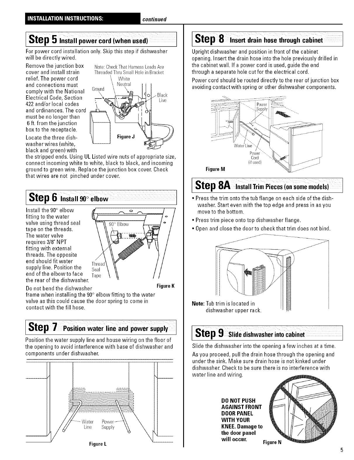
Step5 InStall power cord (when used)
For power cord installation only. Skip this step if dishwasher
will be directly wired.
Removethe junction box
cover and install strain
relief. The power cord
and connections must Ground
comply with the National 7_\
Electrical Code,Section
422and/or local codes
and ordinances. The cord
must be no longer than
6ft. from the junction
box to the receptacle.
Locate the three dish-
washer wires (white,
black and green) with
Note: Check That Harness LeadsAre
Threaded Thru Small Hole in Bracket
White
Neutral
/Black
Live
FigureJ
the stripped ends. Using UL Listed wire nuts of appropriate size,
connect incoming white to white, black to black, and incoming
ground to green wire. Replacethe junction box cover. Check
that wires are not pinched under cover.
[Step6,nstall90o elbow
Install the 90° elbow
fitting to the water
valve using thread seal
tape on the threads.
The water valve
requires 3/8"NPT
fitting with external
threads. The opposite /
end should fit water Thread
supply line. Position the Seal
end ofthe elbowto face Tape
the rear of the dishwasher.
Do not bend the dishwasher
frame when installing the 90° elbow fitting to the water
valve as this could cause the door spring to come in
contact with the fill hose.
Figure K
Step 7 Positionwater line and power supply
Position the water supply line and house wiring onthe floor of
the opening to avoid interference with base of dishwasher and
components under dishwasher.
Line Supply
Figure L
Istep 8Insert drain hose through cabinet ]
Upright dishwasher and position in front of the cabinet
opening. Insert the drain hose into the hole previously drilled in
the cabinet wall. If a power cord is used, guidethe end
through a separate hole cut for the electrical cord.
Power cord should berouted directly to the rear of junction box
avoiding contactwith spring or other dishwasher components.
Watel
Power "'.,
Cord "'-
(if used)
Figure M
[Step8A ,sta,TrimPieces(onsomemodels)J
•Pressthe trim onto the tub flange on each side of the dish-
washer. Start even with the top edge and press in as you
moveto the bottom.
• Presstrim piece onto top dishwasher flange.
• Openand close the door to check that trim does not bind.
j..j"f
Note:Tubtrim is located in
dishwasher upper rack.
[Step9 Slide dishwasherintocabinet
Slide the dishwasher into the opening a few inches at a time.
As you proceed, pull the drain hose through the opening and
under the sink. Make sure drain hose is not kinked under
dishwasher. Checkto be sure there is no interference with
water line and wiring.
DONOT PUSH
AGAINSTFRONT
DOORPANEL
WITH YOUR
KNEE.Damageto
the doorpanel
will occur. FigureN
continued
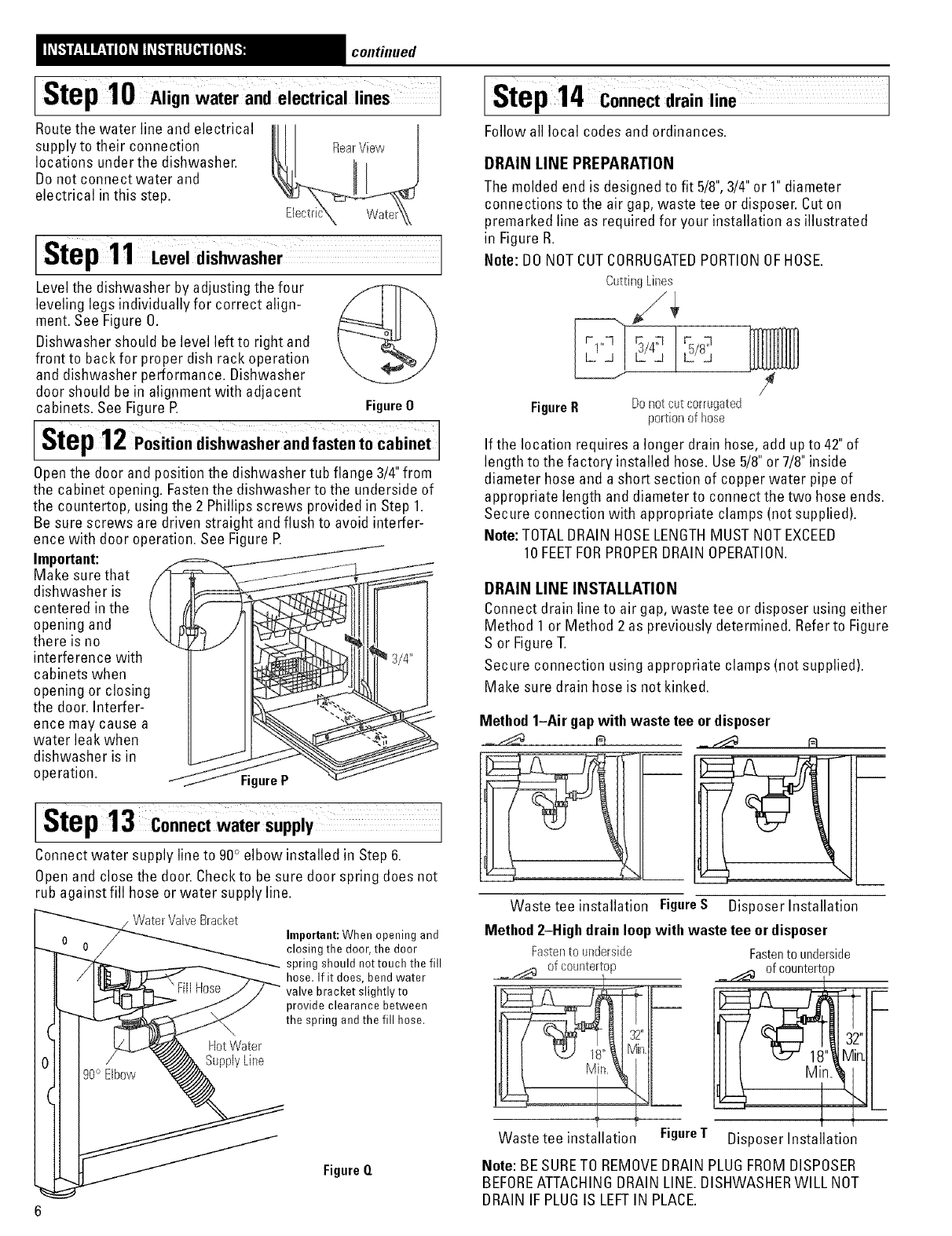
lStep 10 Align water andelectrical lines J
Routethe water line and electrical ill
supply to their connection Ill RearView
locations under the dishwasher. IE_F_c_&_,
Do not connect water and
electrical in this step.
Step11 Leveldishwasher
Level the dishwasher by adjusting the four
leveling legs individually for correct align-
ment. See Figure O.
Dishwasher should belevel left to right and
front to back for proper dish rack operation
and dishwasher performance. Dishwasher
door should be in alignment with adjacent
cabinets. See Figure R Figure0
[Step12Position dishwasher and fasten to cabinet
Openthe door and position the dishwasher tub flange 3/4"from
the cabinet opening. Fasten the dishwasher to the underside of
the countertop, using the 2 Phillips screws provided in Step 1.
Be sure screws are driven straight and flush to avoid interfer-
ence with door operation. See Figure R
Important:
Make sure that
dishwasher is
centered in the
opening and
there is no
interference with
cabinets when
opening or closing
the door. Interfer-
ence may cause a
water leak when
dishwasher is in
operation. Figure P
Step13
Connect water supply line to 90° elbow installed in Step 6.
Open and close the door. Check to be sure door spring does not
rub against fill hose or water supply line.
Bracket
Hot Water
Supply Line
Important:When opening and
closing the door, the door
spring should nottouch the fill
hose. If it does, bend water
valve bracket slightly to
provide clearance between
the spring and the fill hose.
Figure Q
Step 14 Connect drain line 1
Follow all local codes and ordinances.
DRAIN LINE PREPARATION
The molded end is designed to fit 5/8",3/4"or 1"diameter
connections to the air gap, waste tee or disposer. Cut on
premarked line as required for your installation as illustrated
in Figure R.
Note: 130NOTCUTCORRUGATEDPORTIONOFHOSE.
Cutting Lines
FigureR Donot cut corrugated
portionof hose
/
If the location requires a longer drain hose, add up to 42"of
length to the factory installed hose. Use 5/8"or 7/8"inside
diameter hose and a short section of copper water pipe of
appropriate length and diameter to connect the two hose ends.
Secure connection with appropriate clamps (not supplied).
Note: TOTALDRAIN HOSELENGTHMUST NOTEXCEED
10 FEETFORPROPERDRAIN OPERATION.
DRAIN LINE INSTALLATION
Connect drain line to air gap, waste tee or disposer using either
Method 1 or Method 2 as previously determined. Referto Figure
S or Figure T.
Secure connection using appropriate clamps (not supplied).
Make sure drain hose is not kinked.
Method 1-Air gapwith waste tee ordisposer
Waste tee installation FigureS Disposer Installation
Method 2-High drain loop with waste tee or disposer
Fasten to underside
__ of countertop
J
Waste tee installation FigureT
Fasten to underside
_ _ ofcountertop
32"
Disposer Installation
Note: BESURETO REMOVEBRAIN PLUGFROMDISPOSER
BEFOREATTACHINGBRAIN LINE. DISHWASHERWILL NOT
BRAIN IFPLUGIS LEFTIN PLACE.
continued
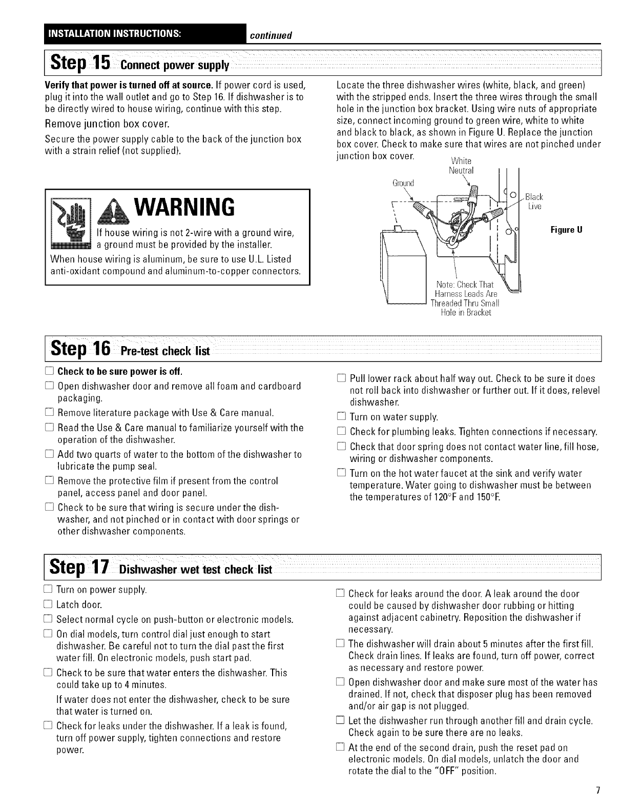
Step15 Connect power supply J
Verifythat power is turnedoff at source. If power cord is used,
plug it into the wall outlet and go to Step 16.If dishwasher is to
be directly wired to house wiring, continue with this step.
Remove junction box cover.
Secure the power supply cable to the back of the junction box
with a strain relief (not supplied).
WARNING
If house wiring is not 2-wire with a ground wire,
a ground must be provided bythe installer.
When house wiring is aluminum, be sure to use U.L.Listed
anti-oxidant compound and aluminum-to-copper connectors.
Locate the three dishwasher wires (white, black, and green)
with the stripped ends. Insert the three wires through the small
hole in the junction box bracket. Using wire nuts of appropriate
size, connect incoming ground to green wire, white to white
and black to black, as shown in Figure U.Replace the junction
box cover. Check to make sure that wires are not pinched under
junction box cover. White
Neutral
.... .Black
Live
FigureU
I
HobinBracket
Step16 Pre4est checklist
[] Checkto be sure power is off. [] Pull lower rack about half way out. Checkto be sure it does
[] Open dishwasher door and remove all foam and cardboard not roll back into dishwasher or further out. If it does, relevel
packaging.
[] Remove literature package with Use & Care manual.
[] Readthe Use& Care manual to familiarize yourself with the
operation of the dishwasher.
[] Add two quarts of water to the bottom of the dishwasher to
lubricate the pump seal.
[] Removethe protective film if present from the control
panel, access panel and door panel.
[] Check to be sure that wiring is secure under the dish-
washer, and not pinched or in contact with door springs or
other dishwasher components.
dishwasher.
[] Turn on water supply.
[] Check for plumbing leaks. Tighten connections if necessary.
[] Check that door spring does not contact water line, fill hose,
wiring or dishwasher components.
[] Turn on the hot water faucet at the sink and verify water
temperature. Water going to dishwasher must be between
the temperatures of 120°Fand 150°E
lStep 17 Dishwasher wet test CheCk list
[] Turn on power supply. [] Check for leaks around the door. A leak around the door
[] Latch door.
[] Select normal cycle on push-button or electronic models.
[] Ondial models, turn control dial just enough to start
dishwasher. Be careful notto turn the dial pastthe first
water fill. Onelectronic models, push start pad.
[] Check to be sure that water enters the dishwasher. This
could take up to 4 minutes.
If water does not enter the dishwasher, check to be sure
that water is turned on.
[] Check for leaks under the dishwasher. If a leak is found,
turn off power supply, tighten connections and restore
power.
could be caused by dishwasher door rubbing or hitting
against adjacent cabinetry. Reposition the dishwasher if
necessary.
[] The dishwasher will drain about 5 minutes after the first fill.
Check drain lines. If leaks are found, turn off power, correct
as necessary and restore powe£
[] Opendishwasher door and make sure most of the water has
drained. If not, check that disposer plug has been removed
and/or air gap is not plugged.
[] Let the dishwasher run through another fill and drain cycle.
Check again to be sure there are no leaks.
[] Atthe end of the second drain, push the reset pad on
electronic models. Ondial models, unlatch the door and
rotate the dial to the "OFF" position.
continued
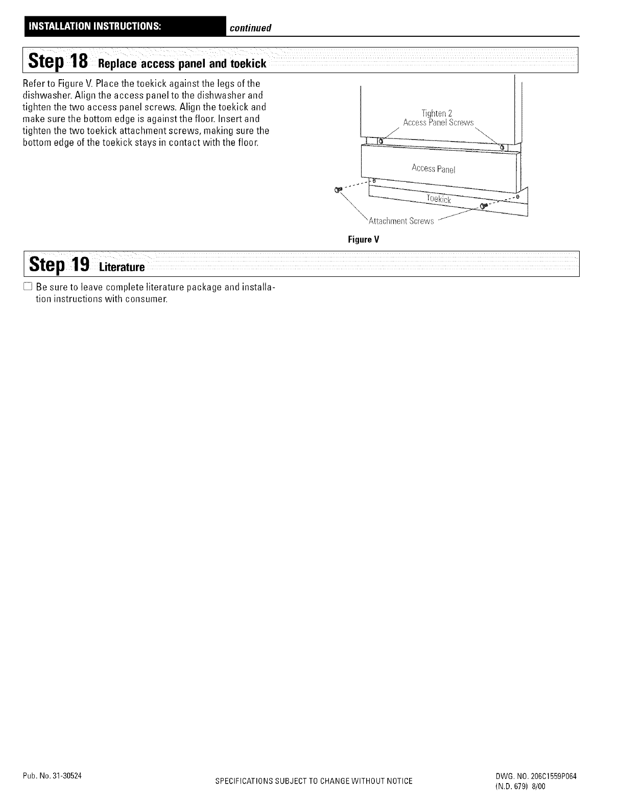
lStep 18 Replaceaccess panel and toekick
Refer to Figure V. Place the toekick against the legs of the
dishwasher. Align the access panel to the dishwasher and
tighten the two access panel screws. Align the toekick and
make sure the bottom edge is againstthe floor. Insert and
tighten the two toekick attachment screws, making sure the
bottom edge of the toekick stays in contact with the floor.
Tighten2
AccessPanelScrews
/--...
Access Panel
FigureV
Step19 Literature
[] Be sure to leave complete literature package and installa-
tion instructions with consumer.
Pub, No.31-30524 DWG. NO.206C1559P064
SPECIFICATIONSSUBJECT TO CHANGEWITHOUT NOTICE (N.B. 679) 8/00
