GE Upright Freezer Manual L0523276
User Manual: GE GE Upright Freezer Manual GE Upright Freezer Owner's Manual, GE Upright Freezer installation guides
Open the PDF directly: View PDF ![]() .
.
Page Count: 20

GE Monogram ®
Installation
Instructions
Stainless Steel
36" Built-In
Refrigerators
and Freezers
Modds
ZIRS36N LH- All Refiqgemtor
ZIRS 36N RH- All Refiqgemtor
ZIFS36N LH- All b)'wezer
ZIFS 36N RH- A ll F_vezer
Before you begin - Readthese instructions completely and carefully.
IMPORTANT- Save these instructions for local inspector's use.
IMPORTANT- OBSERVEALL GOVERNINGCODESAND ORDINANCES.
Note to Installer- Be sure to leave these instructions with the Consumer.
Note to Consumer- Keep these instructions with your Owner's Manual for future reference.
Inrlv/'.4 This appliance must be properlygrounded.See "Grounding the Refrigerator,"page 7.
[.pl___i_BIII _] i,_i II Ill i,_| Cetappareil dolt _tre correctement mis a la terre.Consulter(<Mise aterre durefrigerateur _, page 7.
If you received a damaged product, you should
immediately contact your dealer or builder. Proper
installation is the responsibility of the installer. Product
failure due to improper installation is not covered under
the GEAppliance Warranty. See the Owner's Manual
for wa rra nty information.
ForMonogramlocal service ill yourarea,
1.800.444.1845.
ForMonogramService in Canada,
1.888.880.3030.
ForMonogramParts and Accessories,call
1.800.626.2002.
Due to the weight and size of this refrigerator, and
to reduce the risk of personal injury or damage to
the product -THREE PEOPLEARE REQUIREDFOR
PROPERINSTALLATION.
_, cause du poids et de la taille de ce refrigerator et
pour r_duire le risque de blessure et de dommages,
IL FAUTTROISPERSONNESPOURFAIRE
L'INSTALLATIONCORRECTEMENT.
•Usethis appliance only for its intended purpose.
• Immediately repair or replace electric service
cords that have become frayed or damaged.
• Unplug the refrigerator before cleaning or making
repairs.
• Repairs should be made by a qualified service
technician.
• II ne faut utiliser cet appareil que pour I'usage
pour lequel il a 6te construit.
• II faut rGparer ou remplacer immediatement tout
cordon d'alimentation 61ectrique effiloch6 ou
endommag&
• D_brancher le rGfrig_rateur avant le nettoyage ou
toute intervention.
• Les rGparations doivent _tre faites par un
technicien qualifi&
Contents DesignInformation
Flushor Semi-Flush Enclosure Installations ........3
Enclosure Cutout and Product Dimensions .....3, 4
Accessory Grille Panel Kits.....................................4
Installation Examples ...........................................4, 5
Product Dimensions .................................................5
Installation Preparation
Clearances .................................................................6
Electrical and Water Connection Location ..........6
Groundingthe Refrigerator .....................................7
Tools Required ...........................................................8
Materials Required ...................................................8
Hardware Supplied ...................................................8
Hardware Recommendations .................................8
Flooring .......................................................................8
Step 1: RemovePackaging ......................................8
Installation Instructions
Step 2: Install Water Line.........................................9
Step 3: Install Side Panels .....................................10
Step 4: Install Anti-Tip Brackets ...........................10
Step 5: Level Refrigerator ......................................11
Step 6: Optional Anti-Tip Precaution ...................11
Step 7: ConnectWater Supply ..............................12
Step 8: Connect Power ..........................................12
Step 9: Mount Top Grille Panel .............................12
Step 10:Adjust Door Alignment ..........................13
Step 11: Install Toekick...........................................13
Step 12: Set Temperature Controls ......................13
Step 13:Start Icemaker .........................................13
Problem Solving ......................................................13
ZUGSSUnified Grille Panel Kit..............................14
Advance Planning
Design Infi)rmation
36" Stai*_le,s,_ Steel R_fi'ig'erator,s, t;reezer,s
Flush or
Semi-Flush
Enclosure
Installations
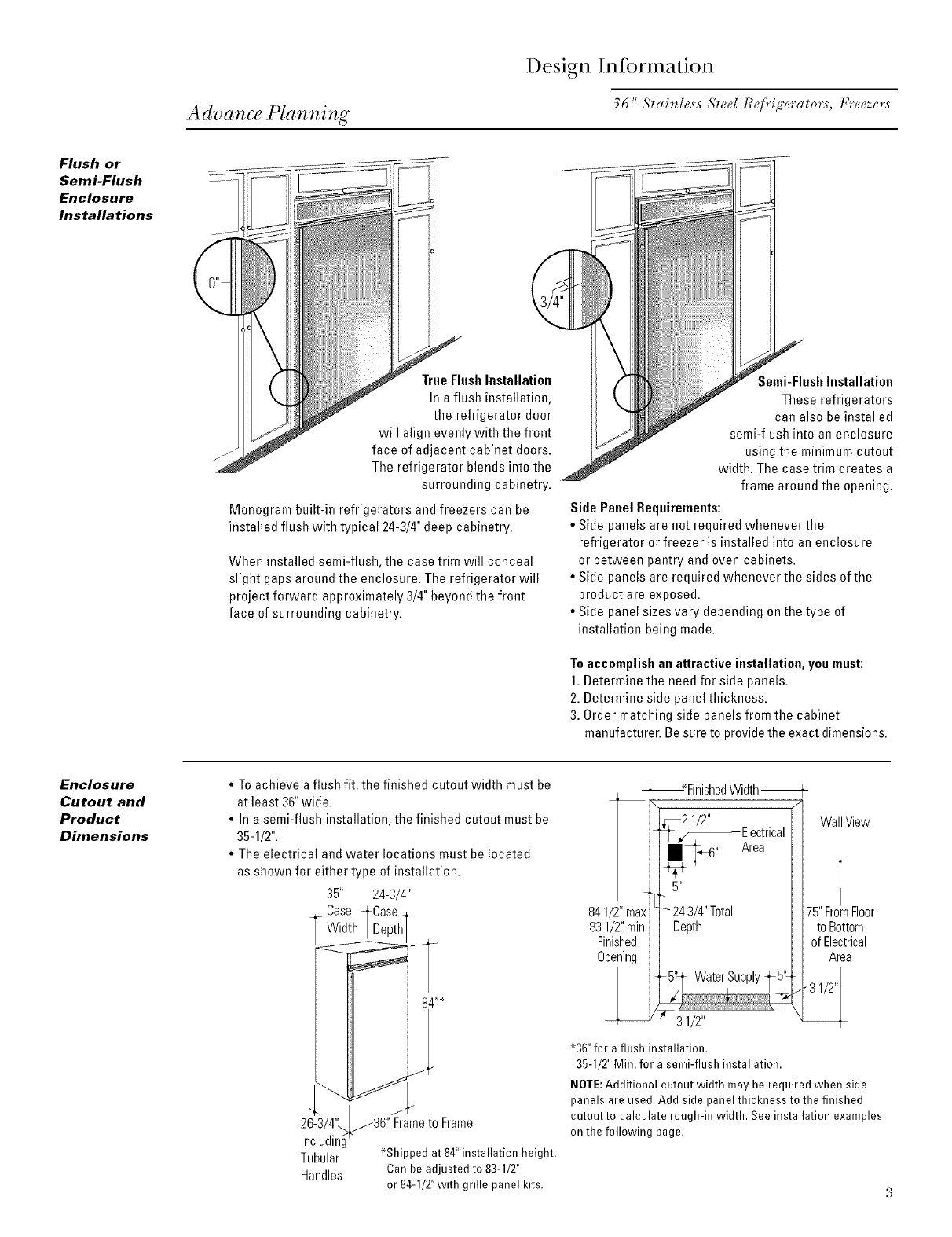
True FlushInstallation
In a flush installation,
the refrigerator door
will align evenly with the front
face of adjacent cabinet doors.
The refrigerator blends into the
surrounding cabinetry.
Monogram built-in refrigerators and freezers can be
installed flush with typical 24-3/4"deep cabinetry.
When installed semi-flush, the case trim will conceal
slight gaps around the enclosure. The refrigerator will
project forward approximately 3/4" beyond the front
face of surrounding cabinetry.
Semi-Flush Installation
These refrigerators
can also be installed
semi-flush into an enclosure
using the minimum cutout
width. The case trim creates a
frame around the opening.
Side Panel Requirements:
•Side panels are not required whenever the
refrigerator or freezer is installed into an enclosure
or between pantry and oven cabinets.
• Side panels are required whenever the sides of the
product are exposed.
• Side panel sizes vary depending on the type of
installation being made.
To accomplish an attractive installation, you must:
1. Determine the need for side panels.
2. Determine side panel thickness.
3. Order matching side panels from the cabinet
manufacturer. Be sure to provide the exact dimensions.
Enclosure
Cutout and
Product
Dimensions
• To achieve a flush fit, the finished cutout width must be
at least 36" wide.
• In a semi-flush installation, the finished cutout must be
35-1/2".
• The electrical and water locations must be located
as shown for either type of installation.
35" 24-3/4"
Case _Case
_ Width|Depth
2G3/4"_36" Frame to
Including
Tubular
Handles
84 .+_
Frame
_Shipped at 84" installation height.
Can be adjusted to 83-1/2"
or 84-1/2" with grille panel kits.
_r _Finish_ Width
'I_ _/_ Electrical
_5,,_6,, Area
841/2" max - 24 3/4" Total
83 1/2" rain Depth
Finished
Opening
31/2"
WallView
75" FromFloor
to Bottom
of Electrical
Area
'36" for a flush installation.
35-1/2" Min. for a semi-flush installation.
NOTE:Additional cutout width may be required when side
panels are used. Add side panel thickness to the finished
cutout to calculate rough-in width. See installation examples
on the following page.
Design Infi)rmation
36" Slair_le,v_ Sl_,d R@'ig'_,ralor,s, Fre_,z_,r,s
Side By Side
Installation
Of Freezer
And Refrigerator
841/2"max
831/2"min
Finished
Opening
31/2"
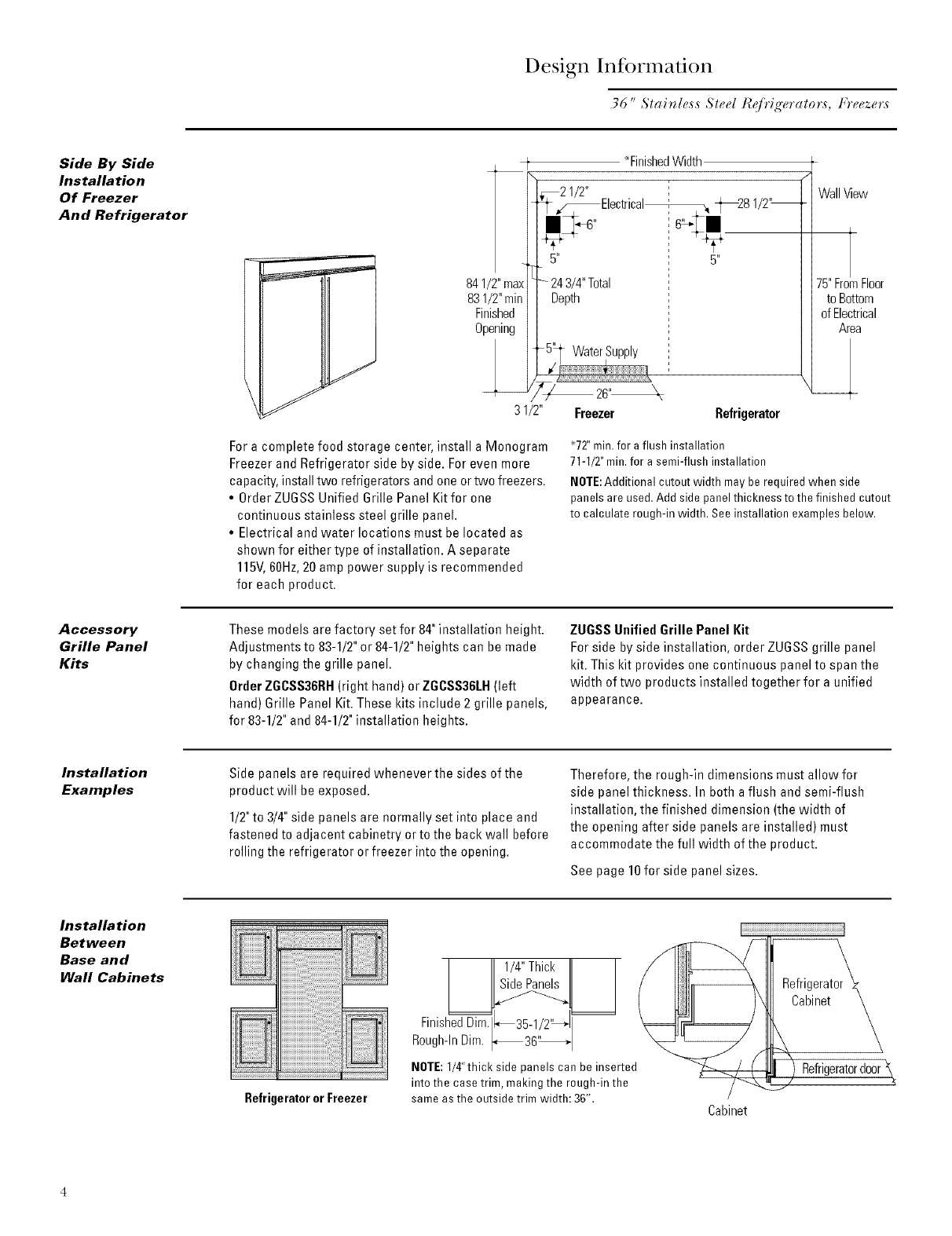
Fora complete food storage center, install a Monogram
Freezer and Refrigerator side by side. For even more
capacity, install two refrigerators and one ortwo freezers.
• Order ZU6SS Unified 6rille Panel Kit for one
continuous stainless steel grille panel.
• Electrical and water locations must be located as
shown for either type of installation. A separate
115V,6OHz,20 amp power supply is recommended
for each product.
*FinishedWidth
_21/2"
"JF_Electrical_ _281/2"_
• _-4" 6q. •
5" 5"
243/4"Total
Depth
Freezer Refrigerator
WallView
75"FromFloor
to Bottom
of Electrical
Area
'72" min. far a flush installation
71-1/2" min.for a semi-flush installation
NOTE:Additional cutout width may be required when side
panels are used. Add side panel thickness to the finished cutout
to calculate rough-in width. See installation examples below.
Accessory
Grille Panel
Kits
These models are factory set for 84" installation height.
Adjustments to 83-1/2"or 84-1/2"heights can be made
by changing the grille panel.
Order ZGCSS36RH(right hand) or ZGCSS36LH(left
hand) 6rille Panel Kit. These kits include 2 grille panels,
for 83-1/2"and 84-1/2"installation heights.
ZUGSS Unified Grille Panel Kit
Forside by side installation, order ZUGSSgrille panel
kit. This kit provides one continuous panel to span the
width of two products installed together for a unified
appearance.
Installation
Examples
Side panels are required whenever the sides of the
product will be exposed.
1/2"to 3/4"side panels are normally set into place and
fastened to adjacent cabinetry or to the back wall before
rolling the refrigerator or freezer into the opening.
Therefore, the rough-in dimensions must allow for
side panel thickness. In both a flush and semi-flush
installation, the finished dimension (the width of
the opening after side panels are installed) must
accommodate the full width of the product.
See page 10 for side panel sizes.
Installation
Between
Base and
Wall Cabinets
Refrigerator or Freezer
1/4"ThickII I
SidePanels ! I
FinishedDb .
Rough-InDim. _36" I
NOTE:1/4"thickside panelscan beinserted
intothe ease trim, making the rough-in the
sameasthe outsidetrim width:36",
Refrigerator_
Refrigeratordoor\
Cabinet
Design Infi rmation
36 "Stair_l_,ss Ste_,l I?_fi'ig'_,rators, Freezers
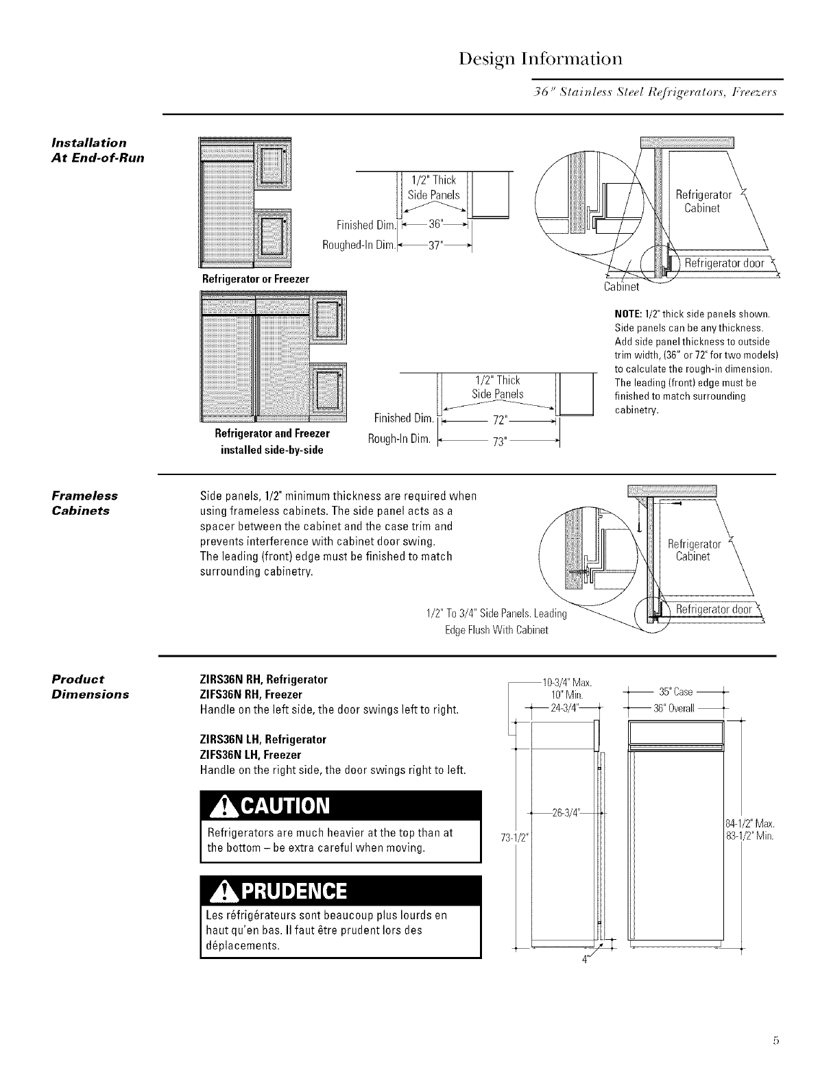
Installation
At End-of-Run
RefrigeratororFreezer
RefrigeratorandFreezer
installedside-by-side
I 1/2"Thick[I I
FioishedOim
Roughed-InDim._3T'_
II 1/2"Thick [I I
II I
FinishedDim _L[_]
Rough-InDim. i 73"_
Cak
Refrigerator_
Cabinet
Refrigeratordoor
NOTE:1/2"thick side panels shown.
Side panels can be anythickness.
Add side panel thickness to outside
trim width, (36" or 72"for two models)
to calculate the rough-in dimension,
The leading (front) edge must be
finished to match surrounding
cabinetry.
Frameless
Cabinets
Side panels, 1/2" minimum thickness are required when
using frameless cabinets. The side panel acts as a
spacer between the cabinet and the case trim and
prevents interference with cabinet door swing.
The leading (front) edge must befinished to match
surrounding cabinetry.
1/2"To3/4" SidePanels.L
EdgeFlushWithCabinet
_ Cabinet_,
_) Refrigeratordoor\
Product
Dimensions
ZIRS36NRH,Refrigerator
ZIFS36NRH, Freezer
Handle on the left side, the door swings left to right.
ZIRS36NLH,Refrigerator
ZIFS36NLH, Freezer
Handle on the right side, the door swings right to left.
Refrigerators are much heavier at the top than at
the bottom - be extra careful when moving.
Les r6frig6rateurs sent beaucoup plus Iourds en
haut qu'en bas. II faut _tre prudentlors des
d6placements.
10-3/4"Max.
10"Miu.
_ 24-3/4"--
2
-- 35"Casef
-- 36"Overall
84-1/2"Max.
83q/2" Min.
Installation Preparation
36 "Slai_le,_,s Steel I?_fi'ig'e*'alo*',s, tcfeezer,s
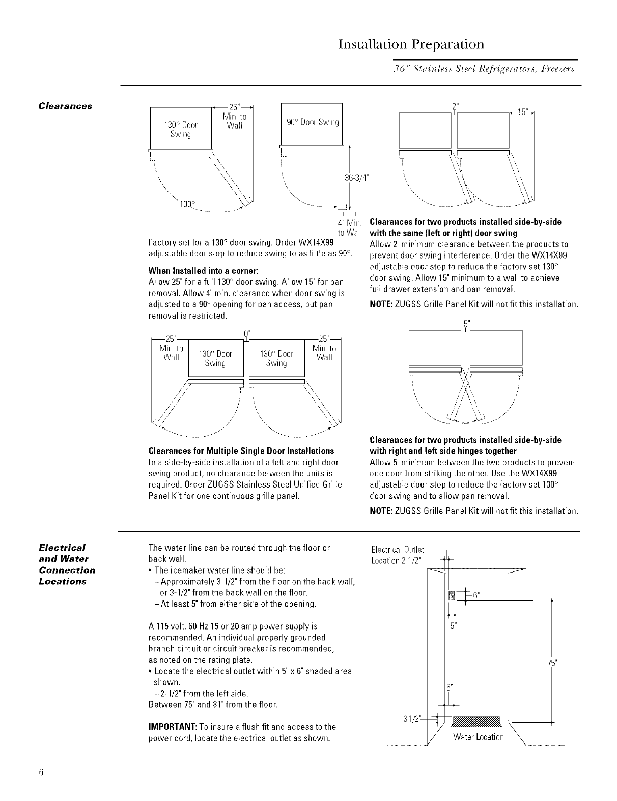
Clearances
Min.to
130° Door Wall
Swing
I
130° ,,y
90° DoorSwing
___ il
,, i
',, Jj36-3/4"
4"_Min.
to Wall
Factory set for a 130° door swing. Order WX14X99
adjustable door stop to reduce swing to as little as 90°.
When Installed into a corner:
Allow 25" for a full 130° door swing. Allow 15"for pan
removal. Allow 4" min. clearance when door swing is
adjusted to a 90° opening for pan access, but pan
removal is restricted.
0 _
--25"--
Min. to
Wall 130° Door 130° Door
Swing Swing
,,1 I I
// //
//"_x
"--- ......... J/
Min.to
Wall
[,,
,,,,,:,
"'-_ ......... JJ
Clearances for Multiple Single Door Installations
In a side-by-side installation of a left and right door
swing product, no clearance between the units is
required. Order ZUGSS Stainless Steel Unified Grille
Panel Kit for one continuous grille panel.
_15%
J"_ ')',
'\ \,
",\',_),, ',\,
........ ;\_>-".............
Clearances for two productsinstalled side-by-side
with the same (left or right) doorswing
Allow 2"minimum clearance between the products to
prevent door swing interference. Order the WX14X99
adjustable door stop to reduce the factory set 130°
door swing. Allow 15"minimum to a wall to achieve
full drawer extension and pan removal.
NOTE:ZUGSS Grille Panel Kit will net fit this installation.
5"
I',,/I [
',""7" I
I" ,,f\ \,, /
,, I\ ,,
/ I \ ,, //
",, ,,,',,' \,'\, /
Clearances for two productsinstalled side-by-side
with rightand left side hinges together
Allow 5"minimum between the two products to prevent
one door from striking the other. Use the WX14X99
adjustable door stop to reduce the factory set 130°
door swing and to allow pan removal.
NOTE:ZUGSS Grille Panel Kit will net fit this installation.
Electrical
and Water
Connection
Locations
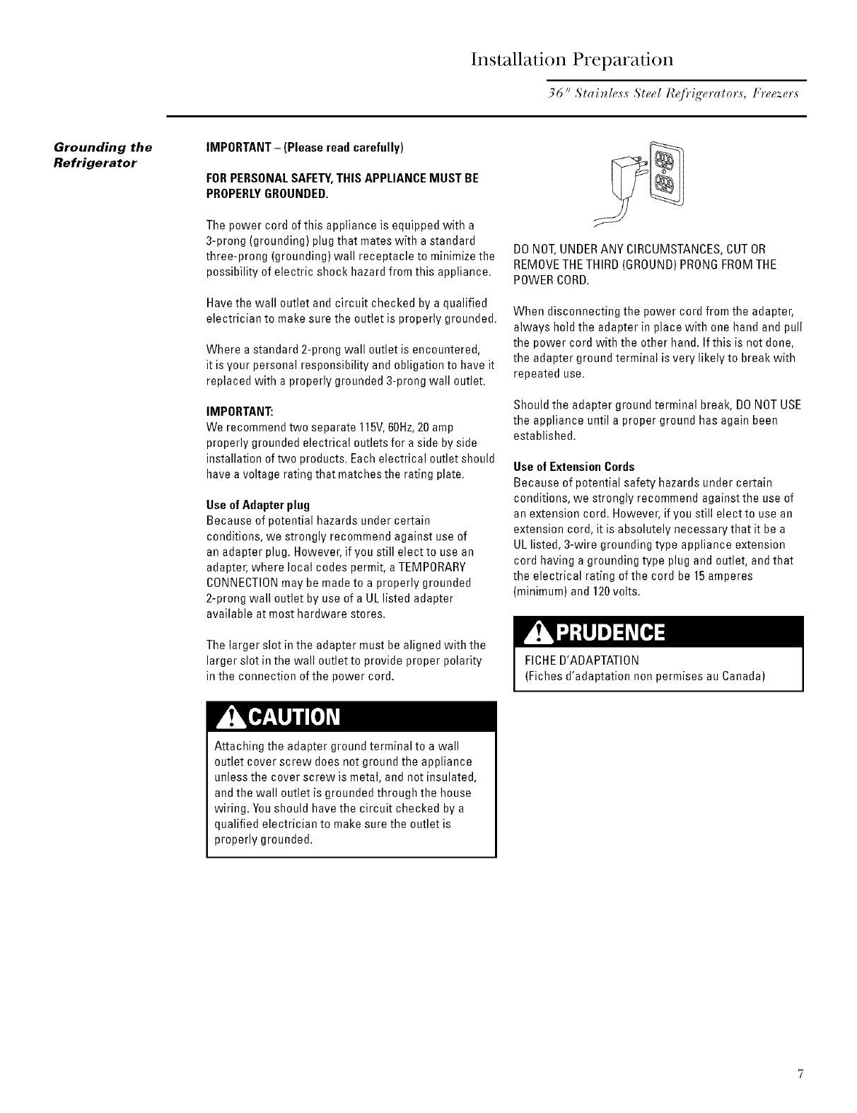
The water line can be routed through the floor or
back wall.
• The icemaker water line should be:
-Approximately 3-1/2" from the floor on the back wall,
or 3-1/2"from the back wall onthe floor.
-At least 5"from either side of the opening.
A 115volt, 60 Hz 15or 20 amp power supply is
recommended. An individual properly grounded
branch circuit or circuit breaker is recommended,
as noted on the rating plate.
• Locate the electrical outlet within 5"x 6" shaded area
shown.
-2-1/2" from the left side.
Between 75"and 81"from the floor.
IMPORTANT:To insure a flush fit and access to the
power cord, locate the electrical outlet as shown.
ElectricalOutlet
Location2 1/2"
31/2,u /
6 '_
/
//////////////////////_
Water Location X
75"
Installation Preparation
36 " ,Stai_le,s,s ,Ste_,l I_fi'ig'_,*'ato*',s, t;*'eeze*',s
Grounding the
Refrigerator
IMPORTANT- (Please read carefully)
FORPERSONALSAFETY,THIS APPLIANCEMUST BE
PROPERLYGROUNDED.
The power cord of this appliance is equipped with a
3-prong (grounding) plug that mates with a standard
three-prong (grounding) wall receptacle to minimize the
possibility of electric shock hazard from this appliance.
Have the wall outlet and circuit checked by a qualified
electrician to make sure the outlet is properly grounded.
Where a standard 2-prong wall outlet is encountered,
it is your personal responsibility and obligation to have it
replaced with a properly grounded 3-prong wall outlet.
IMPORTANT:
We recommend two separate 115V, 60Hz, 20 amp
properly grounded electrical outlets for a side by side
blstallation of two products. Each electrical outlet should
have a voltage rating that matches the rating plate.
Use of Adapter plug
Because of potential hazards under certain
conditions, we strongly recommend against use of
an adapter plug. However, if you still elect to use an
adapter, where local codes permit, a TEMPORARY
CONNECTIONmay be made to a properly grounded
2-prong wall outlet by use of a UL listed adapter
available at most hardware stores.
The larger slot in the adapter must be aligned with the
larger slot in the wall outlet to provide proper polarity
in the connection of the power cord.
DONOT,UNDERANY CIRCUMSTANCES,CUT OR
REMOVETHETHIRD (GROUND)PRONGFROMTHE
POWERCORD.
When disconnecting the power cord from the adapter,
always hold the adapter in place with one hand and pull
the power cord with the other hand. If this is not done,
the adapter ground terminal is very likely to break with
repeated use.
Should the adapter ground terminal break, DONOTUSE
the appliance until a proper ground has again been
established.
Use of Extension Cords
Because of potential safety hazards under certain
conditions, we strongly recommend against the use of
an extension cord. However, if you still elect to use an
extension cord, it is absolutely necessary that it be a
UL listed, 3-wire grounding type appliance extension
cord having a grounding type plug and outlet, and that
the electrical rathlg of the cord be 15 amperes
(minimum) and 120 volts.
FICHED'ADAPTATION
(Fiches d'adaptation non permises au Canada)
Attaching the adapter ground terminal to a wall
outlet cover screw does not ground the appliance
unless the cover screw is metal, and not insulated,
and the wall outlet is grounded through the house
wiring. Youshould have the circuit checked by a
qualified electrician to make sure the outlet is
properly grounded.
Installation Preparation
36" Slai _less St eel R_/?ig'era lots, Ffeezer,s
Tools
Required
• ]qnsnips to cut banding
• Stepladder
• Bucket
• Level
• 1-1/4"open-end wrench
• Appliance hand truck
• Tubing cutter
• 7/16" open-end wrench
•#2 Phillips screwdriver
• Stubby Phillips screwdriver
• Drill and appropriate bits
• 7/16"socket with 3" extension for
ratchet
• Safety glasses
Materials
Required
• 2x4, 35" long, for Anti-]qp support, see page 10
• Stick-on hook and loop fastener strips for 1/4"side panels
• 1/4"copper water line tubing or 6E SmartOonnectTM TubingKit
• Water shut-off valve
• Screws to secure refrigerator to cabinetry
Hardware
Supplied
•1/4-1/4union with nuts
•Anti-tip mounting brackets
Hardware -Water shut-off valve
Recommendations •Water filter WR97X0214
Flooring For proper installation, the refrigerator and freezer must
be placed on a level surface of hard material that is at
the same height as the rest of the flooring. The floor
must be strong enough to support a fully loadedproduct,
or approximately 1,200Ibs.
NOTE:Protect the finish of the flooring. Cut a large
section of the cardboard carton and place under the
product where you are working.
Step 1
Rem o tie
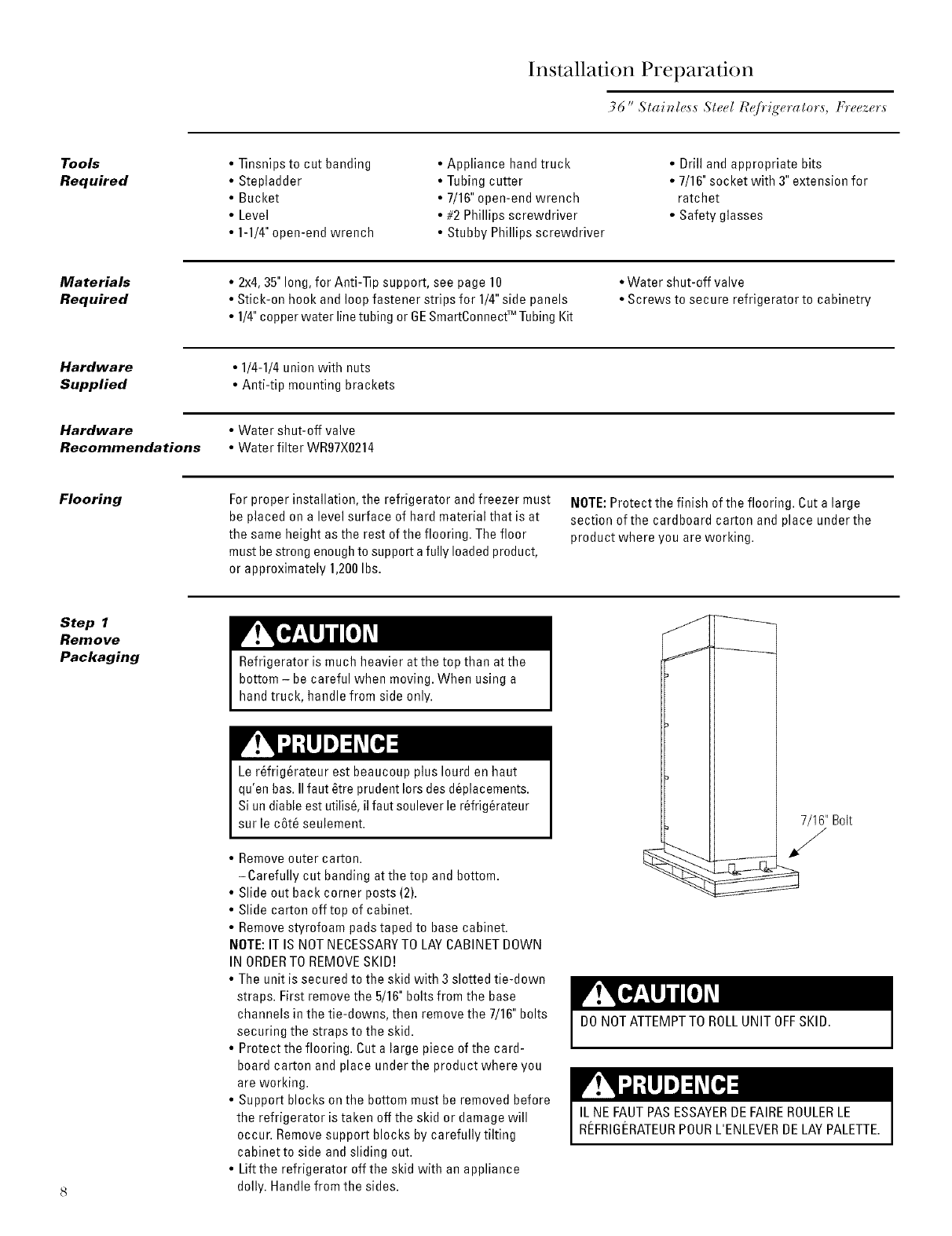
Packaging Refrigerator is much heavier at the top than at the
bottom - be careful when moving. When using a
hand truck, handle from side only.
Ler_frig@ateur est beaucoup plus Iourd en haut
qu'en bas. IIfaut _tre prudent lots des deplacements.
Siun diane est utilis6, il faut soulever le r_frig_rateur
sur le c6t_ seulement.
• Remove outer carton.
-Carefully cut banding at the top and bottom.
• Slide out back corner posts (2).
• Slide carton off top of cabinet.
• Remove styrofoam padstaped to base cabinet.
NOTE:IT IS NOTNECESSARYTO LAYCABINET DOWN
IN ORDERTOREMOVESKID!
• The unit is secured to the skid with 3 slotted tie-down
straps. First remove the 5/16"bolts from the base
channels in the tie-downs, then remove the 7/16" bolts
securing the straps to the skid.
• Protect the flooring. Cut a large piece of the card-
board carton and place under the product where you
are working.
• Support blocks on the bottom must be removed before
the refrigerator is taken off the skid or damage will
occur. Removesupport blocks by carefully tilting
cabinet to side and sliding out.
• Lift the refrigerator off the skid with an appliance
dolly. Handle from the sides.
' Bolt
DONOT ATTEMPTTO ROLLUNIT OFFSKID.
IL NE FAUTPAS ESSAYERDEFAIREROULERLE
REFRIGERATEURPOURL'ENLEVERDELAYPALETTE.
Installation
Step 2
Install
Freezer
Water Line
•A cold water supply is required for automatic
icemaker operation. The water pressure must be
between 20 and 120p.s.i.
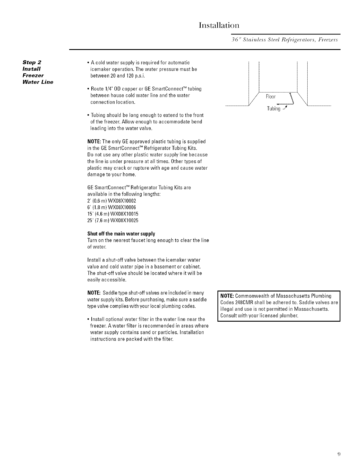
• Route 1/4" ODcopper or 6E SmartConnect:Mtubing
between house cold water line and the water
connection location.
• Tubing should be long enough to extend to the front
of the freezer. Allow enough to accommodate bend
leading into the water valve.
NOTE:The only BEapproved plastic tubing is supplied
in the BE SmartConnectTM Refrigerator Tubing Kits.
Do not use any other plastic water supply line because
the line is under pressure at all times. Other types of
plastic may crack or rupture with age and cause water
damage to your home.
BE SmartConnectTM Refrigerator Tubing Kits are
available in the following lengths:
2' (0.6 m) WX08Xl0OO2
6' (1.8 m) WX08Xl0OO6
15' (4.6m) WX08X10015
25' (7.6m) WX08X10025
Shutoff the main water supply
Turn on the nearest faucet long enough to clear the line
of water.
Install a shut-off valve between the icemaker water
valve and cold water pipe in a basement or cabinet.
The shut-off valve should be located where it will be
easily accessible.
NOTE:Saddletype shut-off valves are included in many
water supply kits. Before purchasing, make sure asaddle
type valve complies with your local plumbing codes.
•Install optional water filter in the water line near the
freezer. A water filter is recommended in areas where
water supply contains sand or particles. Installation
instructions are packed with the filter.
Floor
Tubing J
NOTE:Commonwealth of Massachusetts Plumbing
Codes2480MR shall be adhered to. Saddle valves are
illegal and use is not permitted in Massachusetts.
Consult with your licensed plumber.
Installation
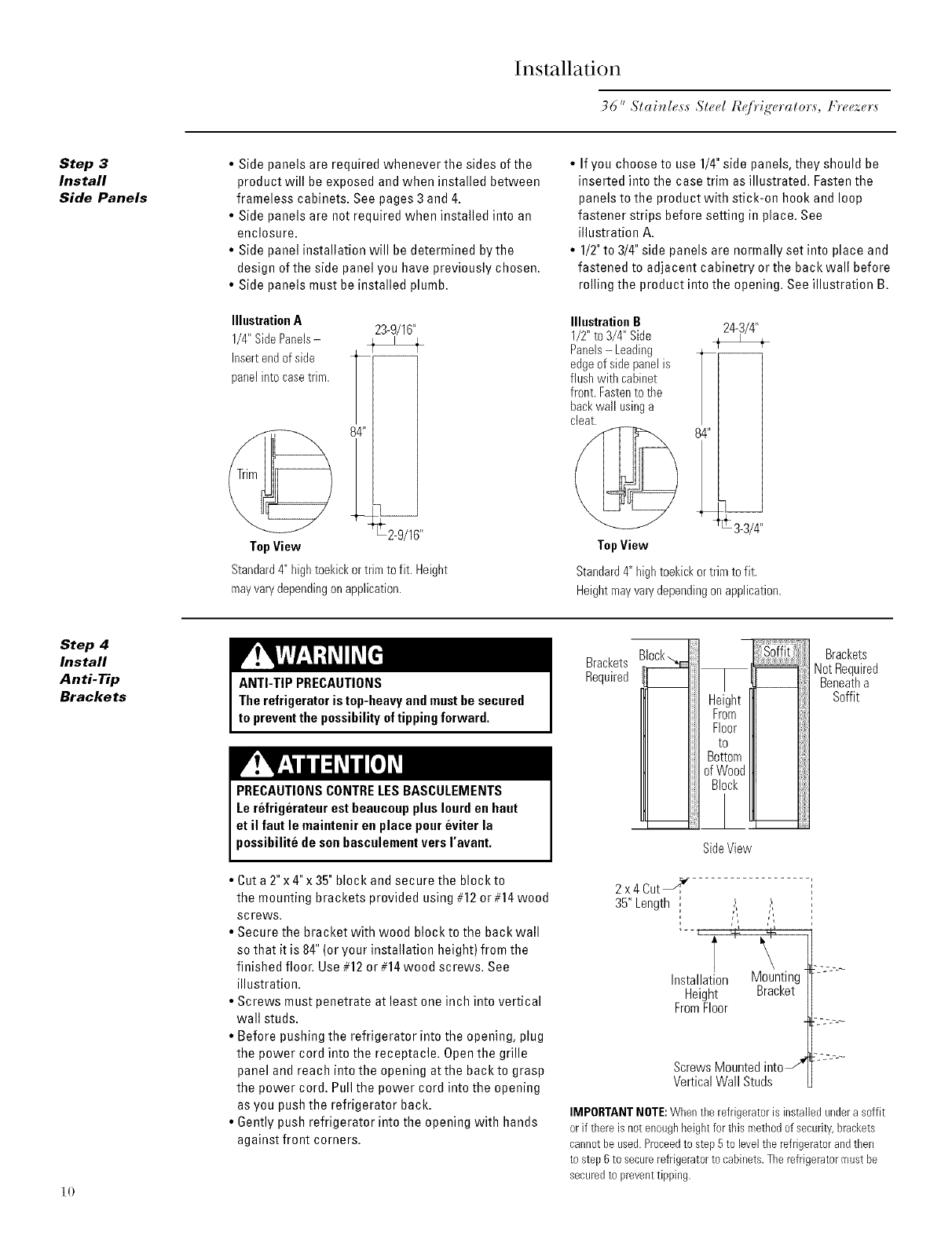
Step 3
Install
Side Panels
•Side panels are required whenever the sides of the
product will be exposed and when installed between
frameless cabinets. See pages 3 and 4.
•Side panels are not required when installed into an
enclosure.
• Side panel installation will be determined bythe
design of the side panel you have previously chosen.
• Side panels must be installed plumb.
Illustration A
1/4" SidePanels-
Insert end of side
panel into casetrim.
23-9/16"
84" _F2-9/16"
TopView
Standard4"hightoekickortrimto fit. Height
mayvarydependingonapplication.
• If you choose to use 1/4"side panels, they should be
inserted into the case trim as illustrated. Fasten the
panels to the product with stick-on hook and loop
fastener strips before setting in place. See
illustration A.
• 1/2"to 3/4"side mnels are normally set into place and
fastened to adjacent cabinetry or the back wall before
rolling the product into the opening. See illustration B.
IllustrationB
1/2"to 3/4" Side
Panels-Leading
edgeofsidepanelis
flushwithcabinet
front.Fastento the
backwall usinga
cleat.
TopView
24-3/4"
T 3_3/4"
Standard 4" high toekick or trim to fit.
Height may vary depending on application.
Step 4
Install
Anti-Tip
Brackets
] 0
ANTI-TIP PRECAUTIONS
Therefrigeratoris top-heavy andmustbe secured
to preventthe possibilityoftipping forward.
PRECAUTIONSCONTRELESBASCULEMENTS
Le refrigcrateur est beaucoupplus Iourd en haut
et il faut le maintenir en place poureviter la
possibilite de sonbasculementvers ravant.
• Cut a 2" x 4"x 35"block and secure the block to
the mounting brackets provided using #12 or #14 wood
screws.
• Secure the bracket with wood block to the back wall
so that it is 84" (or your installation height) from the
finished floor. Use #12 or #14wood screws. See
illustration.
• Screws must penetrate atleast one inch into vertical
wall studs.
• Before pushing the refrigerator into the opening, plug
the power cord into the receptacle. Open the grille
panel and reach into the opening at the back to grasp
the power cord. Pull the power cord into the opening
as you push the refrigerator back.
• 6ently push refrigerator into the opening with hands
against front corners.
Brackets
Required
Height
From
Floor
to
Bottom
ofWood
Block
SideView
Brackets
NotRequired
Beneatha
Soffit
2 x4 CutJ
35"Length
Installation Mounting
Height Bracket
FromFloor
ScrewsMountedintoJ
VerticalWall Studs
IMPORTANTNOTE:Whenthe refrigeratoris installed undera soffit
or if there is not enoughheightfor this methodof security,brackets
cannot be used.Proceedto step5 to levelthe refrigeratorand then
to step6 to securerefrigeratorto cabinets.Therefrigeratormustbe
securedto preventtipping.
Installation
36" Slai_le,s,s S/er./I_/?it_'eralr.',s, Frrwzer,s
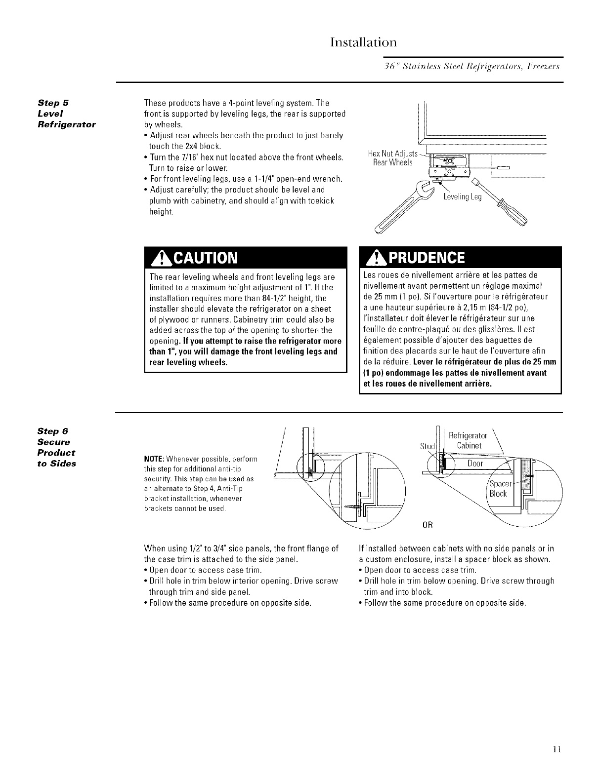
Step 5
Level
Refrigerator
These products have a 4-point leveling system. The
front is supported by leveling legs, the rear is supported
by wheels.
•Adjust rear wheels beneath the product to just barely
touch the 2x4 block.
• Turn the 7/16"hex out located above the front wheels.
Turn to raise or lower.
• Forfront leveling legs, use a 1-1/4"open-end wrench.
• Adjust carefully; the product should be level and
plumb with cabinetry, and should align with toekick
height.
1[
HexNutAdjusts_==_=_==_11 I
RearWheels )[_]1 I
o ZOo o
The rear leveling wheels and front leveling legs are
limited to a maximum height adjustment of 1".If the
installation requires more than 84-1/2" height, the
installer should elevate the refrigerator on a sheet
of plywood or runners. Cabinetry trim could also be
added across the top of the opening to shorten the
opening. If youattempt to raise the refrigerator more
than 1", you will damagethe frontleveling legsand
rear leveling wheels.
Les roues de nivellement arriere et les pattes de
nivellement avant permettent un r6glage maximal
de 25 mm (1 po).Si I'ouverture pour le r_frig_rateur
a une hauteur sup_rieure _ 2,15 m (84-1/2po),
I'installateur dolt _lever le r_frig_rateur sur une
feuille de contre-plaqu6 ou des glissi_res. II est
_galement possible d'ajouter des baguettes de
finition des placards sur le haut de I'ouverture afin
de la r_duire. Leverle refrigerateur de plus de 25mm
(1 po) endommageles pattes de nivellemeet avant
et les rouesde nivellement arriere.
Step 6
Secure
Product
to Sides NOTE:Whenever possible, perform
this step for additional anti-tip
security. This step can be used as
an alternate to Step 4, Anti-Tip
bracket installation, whenever
brackets cannot be used.
_] Refrigerator
Stud__ Cabinet \
ooo-V
When using 1/2"to 3/4" side panels, the front flange of
the case trim is attached to the side panel.
• Open door to access case trim.
• Brill hole in trim below interior opening. Brive screw
through trim and side panel.
• Follow the same procedure on opposite side.
If installed between cabinets with no side panels or in
a custom enclosure, install a spacer block as shown.
• Open door to access case trim.
• Brill hole in trim below opening. Brive screw through
trim and into block.
• Follow the same procedure on opposite side.
]]
Installation
36 "Slai_lr_ss Steel I_e[)'i£'eralr_rs, Ffr_ezers
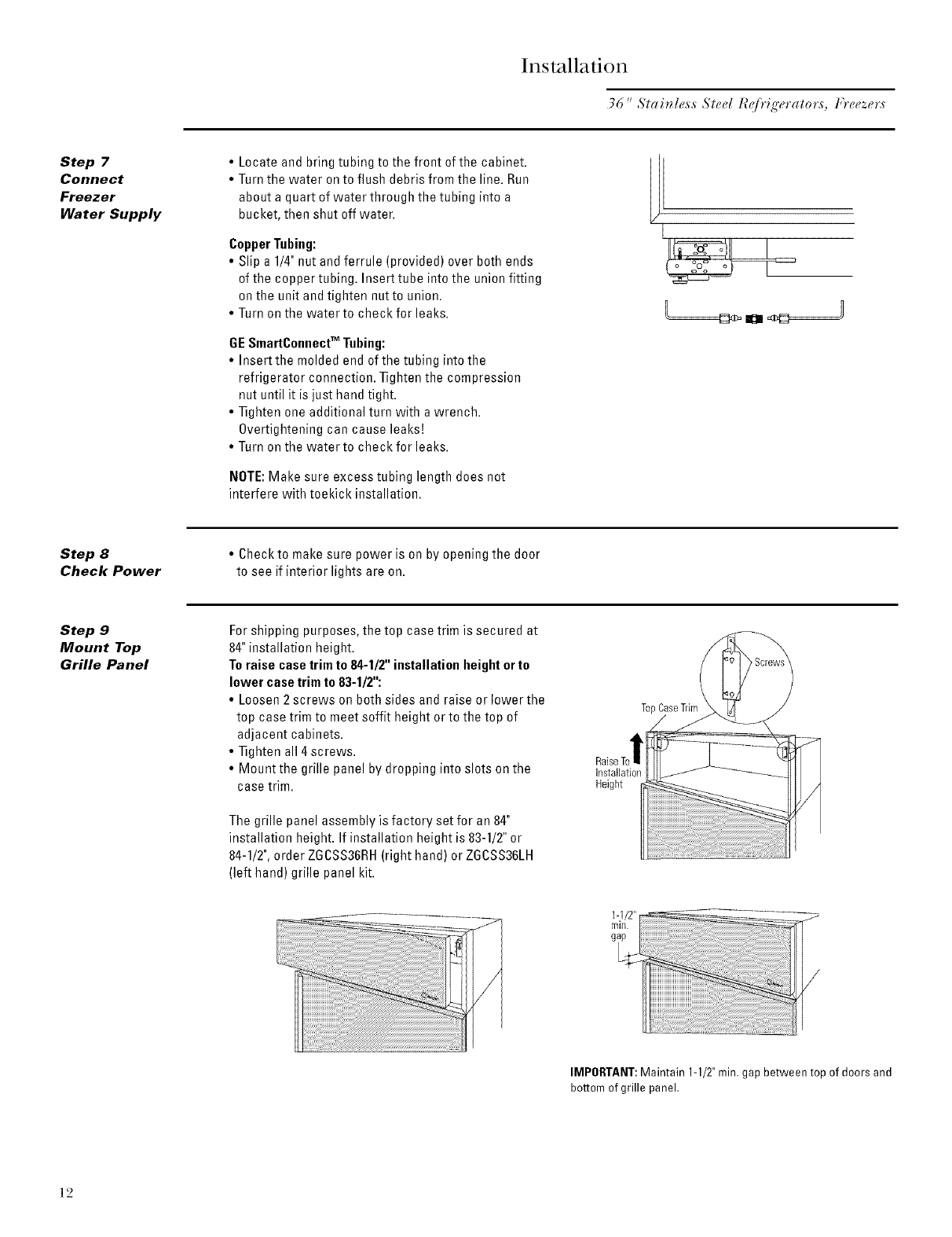
Step 7
Connect
Freezer
Water Supply
•Locate and bring tubing to the front of the cabinet.
• Turn the water on to flush debris from the line. Run
about a quart of water through the tubing into a
bucket, then shut off water.
CopperTubing:
• Slip a 1/4"nut and ferrule (provided) over both ends
of the copper tubing. Insert tube into the union fitting
on the unit and tighten nutto union.
• Turn on the water to check for leaks.
GESmartConnect" Tubing:
• Insertthe molded end of the tubing [ntothe
refrigerator connection. Tighten the compression
nut until it is just hand tight.
• Tighten one additional turn with a wrench.
Overtightening can cause leaksE
• Turn on the water to check for leaks.
NOTE:Make sure excess tubing length does not
interfere with toekick installation.
L[
U
Step 8
Check Power
• Check to make sure power is on by opening the door
to see if interior lights are on.
Step 9
Mount Top
Grille Panel
Forshipping purposes, the top case trim is secured at
84"installation height.
Toraise casetrim to 84-1/2"installation height orto
lower case trim to 83-1/2":
•Loosen2 screws oo both sides and raise or lower the
top case trim to meet soffit height or to the top of
adjacent cabinets.
• Tighten all 4 screws.
• Mount the grille panel by dropping into slots on the
case trim.
The grille panel assembly is factory set for an 84"
installation height. If installation height is 83-1/2"or
84-1/2",order ZGCSS36RH(right hand) or ZGCSS36LH
(left hand) grille panel kit.
TopCaseTrim
Installation
Height
IMPORTANT:Maintain 1-1/2"min. gap between top of doors and
bottom of grille panel.
]2
Installation
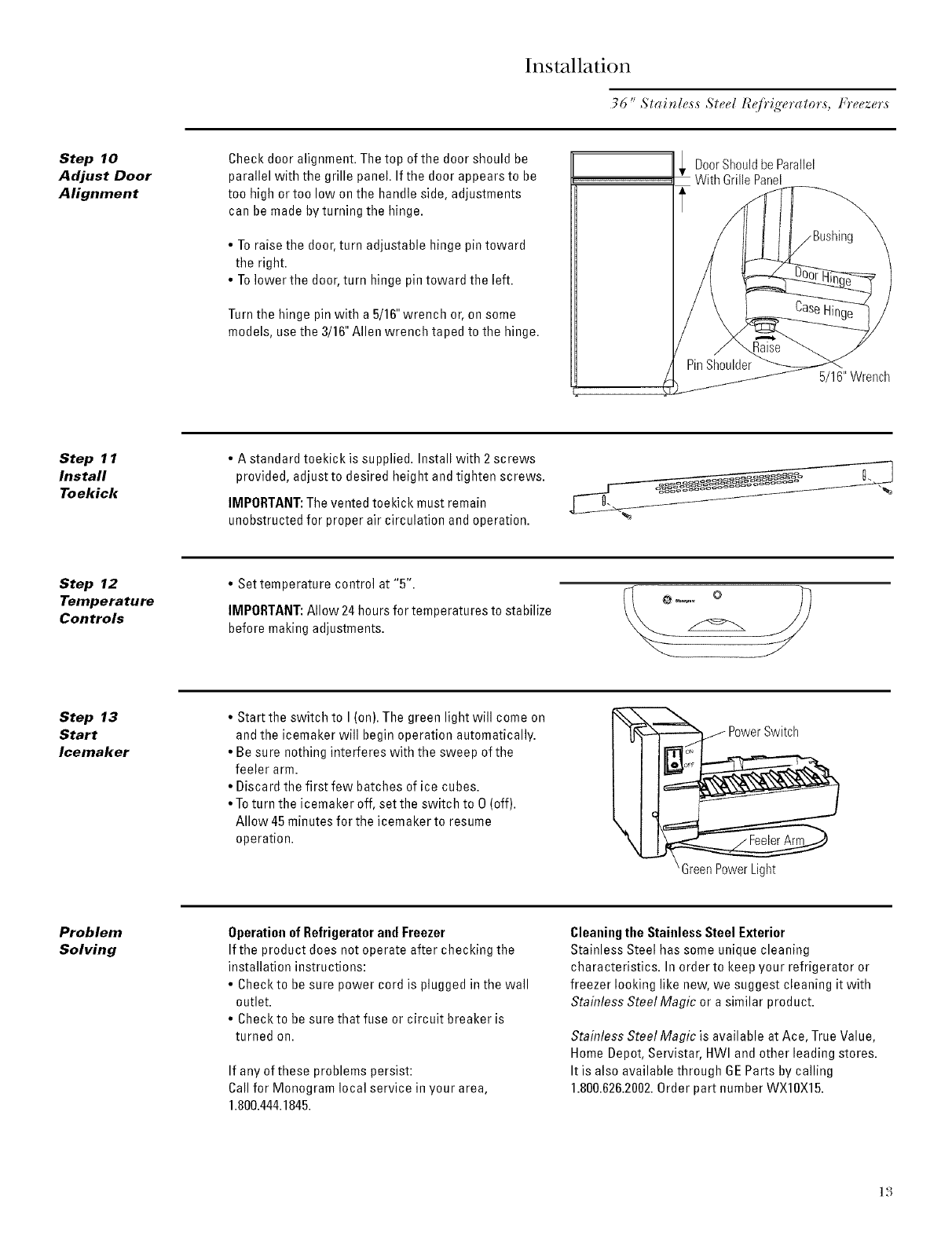
Step 10
Adjust Door
Alignment
Check door alignment. Thetop of the door should be
parallel with the grille panel. If the door appears to be
too high ortoo low on the handle side, adjustments
can be made by turning the hinge.
•To raise the door,turn adjustable hinge pin toward
the right.
• Tolower the door, turn hinge pin toward the left.
Turn the hinge pin with a 5/16"wrench or, on some
models, usethe 3/16" Allen wrench taped to the hinge.
!_ DoorShouldbeParallel
With Grille Panel
5/16" Wrench
Step 11
Install
Toekick
• A standard toekick is supplied. Install with 2 screws
provided, adjust to desired height and tighten screws.
IMPORTANT:The vented toekick must remain
unobstructed for proper air circulation and operation.
Step 12
Temperature
Controls
• Set temperature control at "5".
IMPORTANT:Allow 24 hoursfor temperatures to stabilize
before making adjustments.
Step 13
Start
Icemaker
• Start the switch to I (on). The green light will come on
and the icemaker will begin operation automatically.
• Be sure nothing interferes with the sweep of the
feeler arm.
• Discard the first few batches of ice cubes.
• Toturn the icemaker off, set the switch to O(off).
Allow 45 minutes for the icemaker to resume
operation.
'Green PowerLight
Problem
Solving
Operation of Refrigeratorand Freezer
If the product does not operate after checking the
installation instructions:
• Checkto be sure power cord is plugged in the wall
outlet.
• Check to be sure that fuse or circuit breaker is
turned on.
If any of these problems persist:
Callfor Monogram local service in your area,
1.800.444.1845.
Cleaning the Stainless Steel Exterior
Stainless Steel has some unique cleaning
characteristics. In order to keep your refrigerator or
freezer looking like new, we suggest cleaning it with
Stainless Steel Magic or a similar product.
Stainless Steel Magic is available at Ace, True Value,
Home Depot, Servistar, HWI and other leading stores.
It is also available through 6E Parts by calling
1.800.626.2002.Order part number WX10X15.
]3
Z _ _
U(,SS Trim Kit
Un!/_ed Stainless Steel Custom Grille P_nel
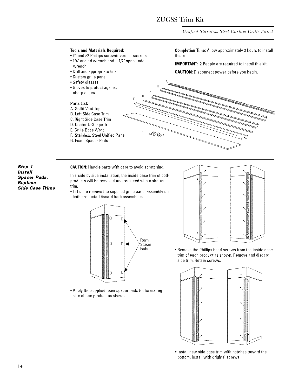
Tools and Materials Required:
•#1 and #2 Phillips screwdrivers or sockets
• 1/4" angled wrench and 1-1/2"open ended
wrench
• Drill and appropriate bits
• Custom grille panel
• Safety glasses
• Glovesto protect against
sharp edges
CompletionTime:Allow approximately 3 hours to install
this kit.
IMPORTANT:2 People are required to install this kit.
CAUTION: Disconnect power before you begin.
A
PartsList:
A. Soffit Vent Top F
B. Left Side CaseTrim --_:/- _._ _ __ _
C.Right Side Case Trim __ _ _
D.Center U-Shape Trim _
E.Grille Base Wrap
F. Stainless Steel Unified Panel
G.Foam Spacer Pads
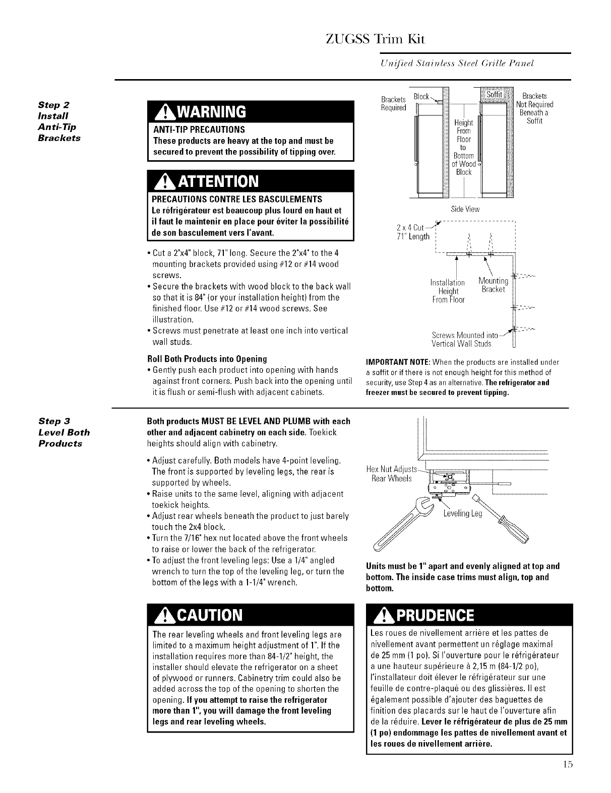
Step 1
Install
Spacer Pads.
Replace
Side Case Trims
CAUTION: Handle parts with care to avoid scratching.
In a side by side installation, the inside case trim of both
products will be removed and replaced with a shorter
trim.
• Lift upto remove the supplied grille panel assembly on
both products. Discard both assemblies.
• Apply the supplied foam spacer pads to the mating
side of one product as shown.
• Removethe Phillips head screws from the inside case
trim of each product as shown. Remove and discard
side trim. Retain screws.
14
• Install new side case trim with notches toward the
bottom. Install with original screws.
ZUGSS Trim Kit
U_!/ir'_! Slainlr,,s,s Sled G*'ille Panel
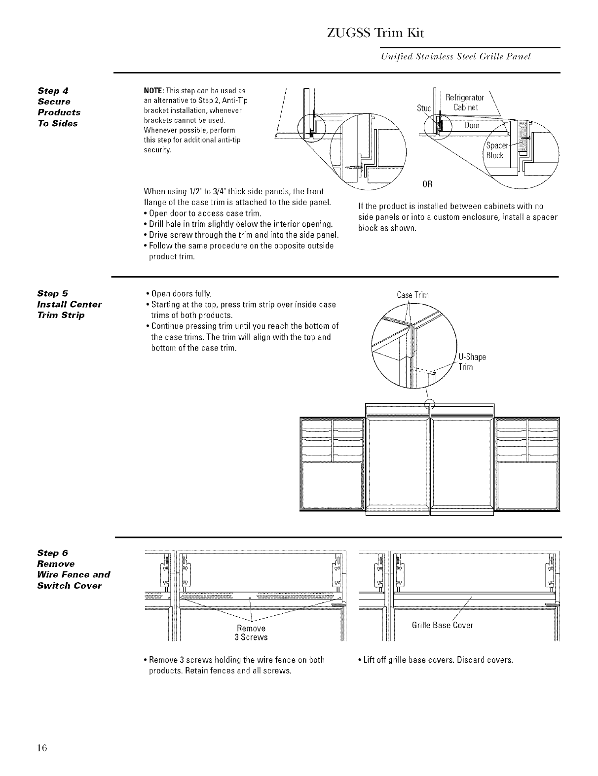
Step 2
Install
Anti-Tip
Brackets ANTI-TIP PRECAUTIONS
Theseproductsare heavy at the top and mustbe
secured to preventthe possibility of tipping over.
Brackets Brackets
Required Not Required
Beneatha
Soffit
PRECAUTIONSCONTRELESBASCULEMENTS
Le refrigerateur est beaucoupplus Iourd en hautet
il faut le maintenir en place poureviter la possibilite
de son basculementvers I'avant.
• Cut a 2"x4"block, 71" long. Secure the 2"x4"to the 4
mounting brackets provided using #12 or #14wood
screws.
• Secure the brackets with wood block to the back wall
so that it is 84"(or your installation height) from the
finished floor. Use#12 or #14 wood screws. See
illustration.
• Screws must penetrate at least one inch into vertical
wall studs.
Roll BothProducts into Opening
•Gently push each product into opening with hands
against front corners. Push back into the opening until
it is flush or semi-flush with adjacent cabinets.
SideView
2 x 4 Cutj._r-
71" Length
Installation Mounting 5:'-"--
Height Bracket
FromFloor
ScrewsMountedinto_'
VerticalWall Studs
IMPORTANT NOTE:When the products are installed under
a soffit or if there is not enough height for this method of
security, use Step 4as analternative. The refrigeratorand
freezer must besecured to preventtipping.
Step 3
Level Both
Products
BothproductsMUST BE LEVELAND PLUMB with each
otherand adjacent cabinetry on each side. Toekick
heights should align with cabinetry.
• Adjust carefully. Both models have 4-point leveling.
The front is supported by leveling legs, the rear is
supported by wheels.
• Raise units to the same level, aligning with adjacent
toekick heights.
• Adjust rear wheels beneath the product to just barely
touch the 2x4 block.
• Turn the 7/16" hex nut located above the front wheels
to raise or lower the back of the refrigerator.
• To adjust the front leveling legs: Use a 1/4"angled
wrench to turn the top of the leveling leg, or turn the
bottom of the legs with a 1-1/4"wrench.
H_xNrU_vAdeJ_SstS_ II
Unitsmustbe 1"apart andevenly aligned attop and
bottom.The inside case trims must align,top and
bottom.
The rear leveling wheels and front leveling legs are
limited to a maximum height adjustment of 1".If the
installation requires more than 84-1/2" height, the
installer should elevate the refrigerator on a sheet
of plywood or runners. Cabinetry trim could also be
added across the top of the opening to shorten the
opening. If youattempt to raise the refrigerator
more than 1",youwill damagethe front leveling
legs and rear leveling wheels.
Les roues de nivellement arriere et les pattes de
nivellement avant permettent un rGglage maximal
de 25 mm (1 pc). Si I'ouverture pour le r_frig_rateur
a une hauteur sup&ieure _ 2,15 m (84-1/2 pc),
I'installateur dolt _lever le r_frig_rateur sur une
feuille de cootre-plaqu6 ou des glissi_res. II est
_galement possible d'ajouter des baguettes de
finition des placards sur le haut de I'ouverture afin
de la r_duire. Lever le refrigerateur de plus de 25 mm
(1 po) endommage les pattes de nivellement avant et
les roues de nivellement arriere.
15
ZUGSS Trim Kit
U*_!fir,d Stai_zless Steel G*'illr, Pa_el
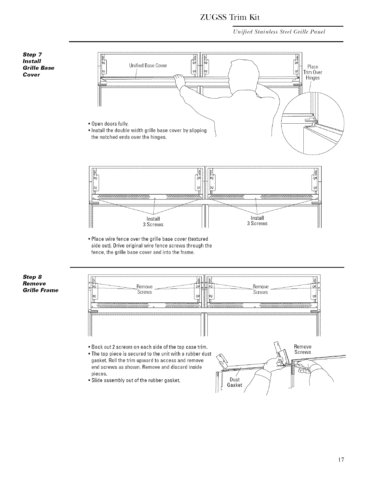
Step 4
Secure
Products
To Sides
NOTE:Thisstep can be used as
an alternative to Step 2,Anti-Tip
bracket installation, whenever
brackets cannot be used.
Whenever possible, perform
this step for additional anti-tip
security.
When using 1/2"to 3/4"thick side panels, the front
flange of the case trim is attached to the side panel.
•Open door to access case trim.
•Drill hole in trim slightly below the interior opening.
• Drive screw through the trim and into the side panel.
• Follow the same procedure onthe opposite outside
product trim.
_/ Refrigerator \
Stud_Cabinet \
OR _
If the product is installed between cabinets with no
side panels or into a custom enclosure, install a spacer
block as shown.
Step 5
Install Center
Trim Strip
• Open doors fully.
• Starting at the top, press trim strip over inside case
trims of both products.
• Continue pressing trim until you reach the bottom of
the case trims. The trim will align with the top and
bottom of the case trim.
CaseTrim
U-Shape
Trim
Step 6
Remove
Wire Fence and
Switch Cover
• Remove 3 screws holding the wire fence on both
products. Retainfences and all screws.
_q
j"
6rille Base Cover
•Lift off grille base covers. Discard covers.
16
ZUGSS Trim Kit
U_z!/_ed Staitzless Steel G*'ille Pa_zel
Step 7
Install
Grille Base
Cover UnifiedBaseCover Place
TrimOver
Hinges
•Open doors fully.
• Install the double width grille base cover by slipping
the notched ends over the hinges.
Install Install
3 Screws 3 Screws
•Place wire fence over the grille base cover (textured
side out). Drive original wire fence screws through the
fence, the grille base cover and into the frame.
Step 8
Remove
Grille Frame emove emove
• Back out 2 screws on each side of the top case trim.
• The top piece is secured to the unit with a rubber dust
gasket. Rollthe trim upward to access and remove
end screws as shown. Removeand discard inside
pieces.
• Slide assembly out of the rubber gasket. Dust
6asket
Remove
Screws
17
ZUGSS Trim Kit
Un!/ied Stainless Slcel Grille Panel
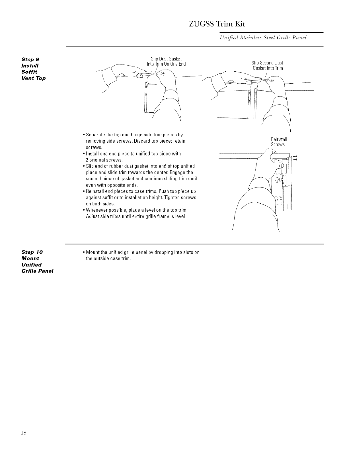
Step 9
Install
Soffit
Vent Top
SlipDustGasket
IntoTrimOnOneEnd Slip Second Dust
Gasket Into Trim
• Separate the top and hinge side trim pieces by
removing side screws. Discard top piece; retain
screws.
• Install one end piece to unified top piece with
2 original screws.
• Slip end of rubber dust gasket into end of top unified
piece and slide trim towards the center. Engage the
second piece of gasket and continue sliding trim until
even with opposite ends.
• Reinstall end pieces to case trims. Pushtop piece up
against soffit or to installation height. Tighten screws
on both sides.
• Whenever possible, place a level on the top trim.
Adjust side trims until entire grille frame is level. \
Screws
Step 10
Mount
Unified
Grille Panel
• Mount the unified grille panel by dropping into slots on
the outside case trim.
18

ZUGSS Trim Kit
Un!fied Stainless Steel Grille Panel
Step 11
Adjust
Door
Alignment
Check door alignment. The top of the door should be
parallel with the grille panel. If the door appears to be
too high ortoo low on the handle side, adjustments can
be made.
• Use a 5/16"wrench to turn the hinge.
•To raise the door, turn adjustable hinge pin toward
the right.
•To lower the door, turn hinge pin toward the left.
5/16" Wrench
19
Pub.No.49-60073-3
PartNo. 197D3003PO01
12-03JR
65161-01
Note: While performing installations described in this book,
safety glasses or goggles should be worn.
• ®
I_or 3lo_wg'ram local _'_Jic_, i_ )our area, call
) 5
l. 800.444. l,_4 .
)
Note: t l-Odtl([ ill]pl'O_(_lll(!ll[ is _ COll[illtlillg ell(l(_a'_OF at
(;(n_ ral Electric. Thor(fore, materials, appearance and
spe(ifi(_ltions are su[)je(I to ( h_lllg(! _,_,illlout noli(e.
Monogram:
GEConsumer Products
General Electric Company
Louisville, KY40225
@2003 General Electric Company
