GENERAL TOOLS and INSTRUMENTS DCS500R Wireless Video Receiver User Manual
GENERAL TOOLS & INSTRUMENTS COMPANY LLC Wireless Video Receiver Users Manual
User Manual
0 V0.2 131015
Multifunction Video Inspection
Model: DCS500T/DCS500R
Operation Manual

1 V0.2 131015
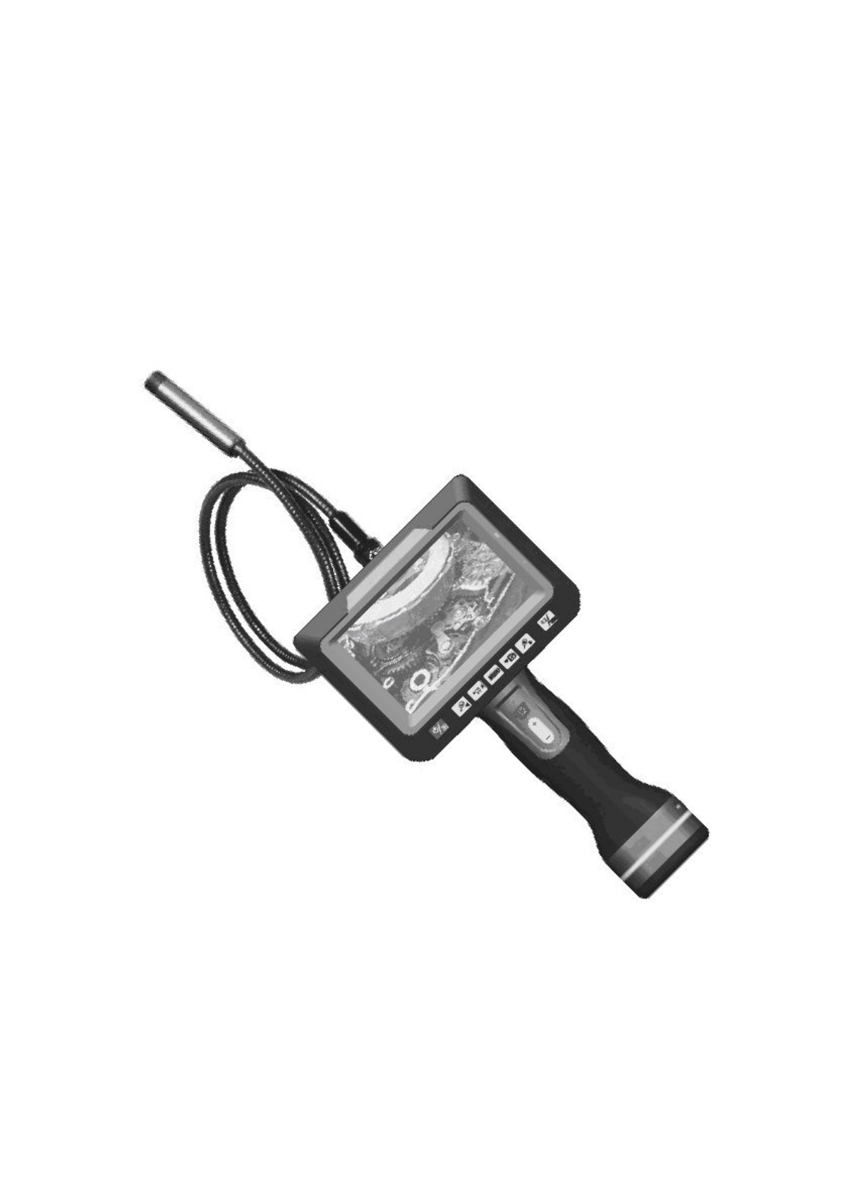
Multifunction Video Inspection
Model:DCS500T/DCS500R
Overview
DCS500T/DCS500R Multifunction video inspection has been designed as a user friendly and economical
way of solving hidden problems and increasing productivity. (eg. Inspect vent pipe and system of air conditioner,
machine equipment, engine and so on).
The product has a high clarity color LCD of 5 ’’ size. It uses an interchangeable 9mm probe and can be
connected to probes with different length and diameter (customized camera head and probes are also available).
The camera head is with adjustable LED lights, which helps you to inspect gaps and holes. The camera head can
equip with several accessories(magnet, mirror, hook etc.), making it more flexible.
DCS500T/DCS500R can take a photo wirelessly .It has built-in polymer lithium battery, also could use AC
adapter for charging with LED indicator. The screen can detach from grip and the grip can control monitor to
take photos and videos. DCS500T/DCS500R has an internal memory (support Micro SD), and is capable to
capture videos and take photos both manually and automatically. It has a built-in microphone and a speaker,
which makes it possible to record and playback sound. The product has a TV output and a USB port, which
allows the users to connect the unit to a TV or a computer. The product also supports image zooming and rotation.
It has the advantages of small size, clear image, stable performance, easy operation and portability. It is widely
used in applications such as the industry, the building, the aviation, the vehicles maintenance.
Safety Instructions
Failure to follow the instructions listed below may result in electric shock or personal injury.
●Read and understand all instructions prior to any operation.
●Do not remove any labels from the tool.
●Keep the work area clean and well lit, cluttered and dark areas may cause accidents.
●Do not operate the tool with the presence of flammable/explosive gases.
●Do not use the product around corrosive chemicals, which can ruin the picture quality.
●Keep bystanders、children and visitors away while operating the tool.
●Stay alert, watch what you are doing and use common sense. A moment of inattention will result in serious
personal injury.
●Do not overreach. Keep proper footing and balance all the time.
●Always wear protective eyewear. Dust mask、non-skid safety shoes、hard hat or hearing protection must be used
for appropriate conditions.
●Do not place this product on any unstable cart or surface. The product may fall causing serial injury to a person
or serious damage to the product.
●For safety please always keep the video inspection away from any kind of liquid. Liquid increases the risk of
2 V0.2 131015
electrical shock and damage to the product.
●Do not use this device for personal or medical use.
●The unit is not shock-resistant. Do not use it as a hammer or drop it.
Battery precautions
● Please use the standard factory power adapter, otherwise will destroy the inside battery.
● Please completely exhaust the power for the first time. And we recommend full charging and full discharging
for the first three times. And the charging time should not less than 5 hours. Fully activate the battery could
play maximum capacity of the built-in battery.
● The charging and discharging time differs because the different power from the factory.
● Please always keep the charging connector away from the metal and oily objects.
● Please fully charging the battery before it is not for use, to make sure the high performance while using.
● Don’t compress and puncture the inside battery.
● Please stop operating if the inside battery is broken.
● Don’t throw the product into fire, which will cause explosion.
● Please dispose the battery properly. High temperature will cause the battery to explode. Please follow the local
regulations for disposing the old battery.
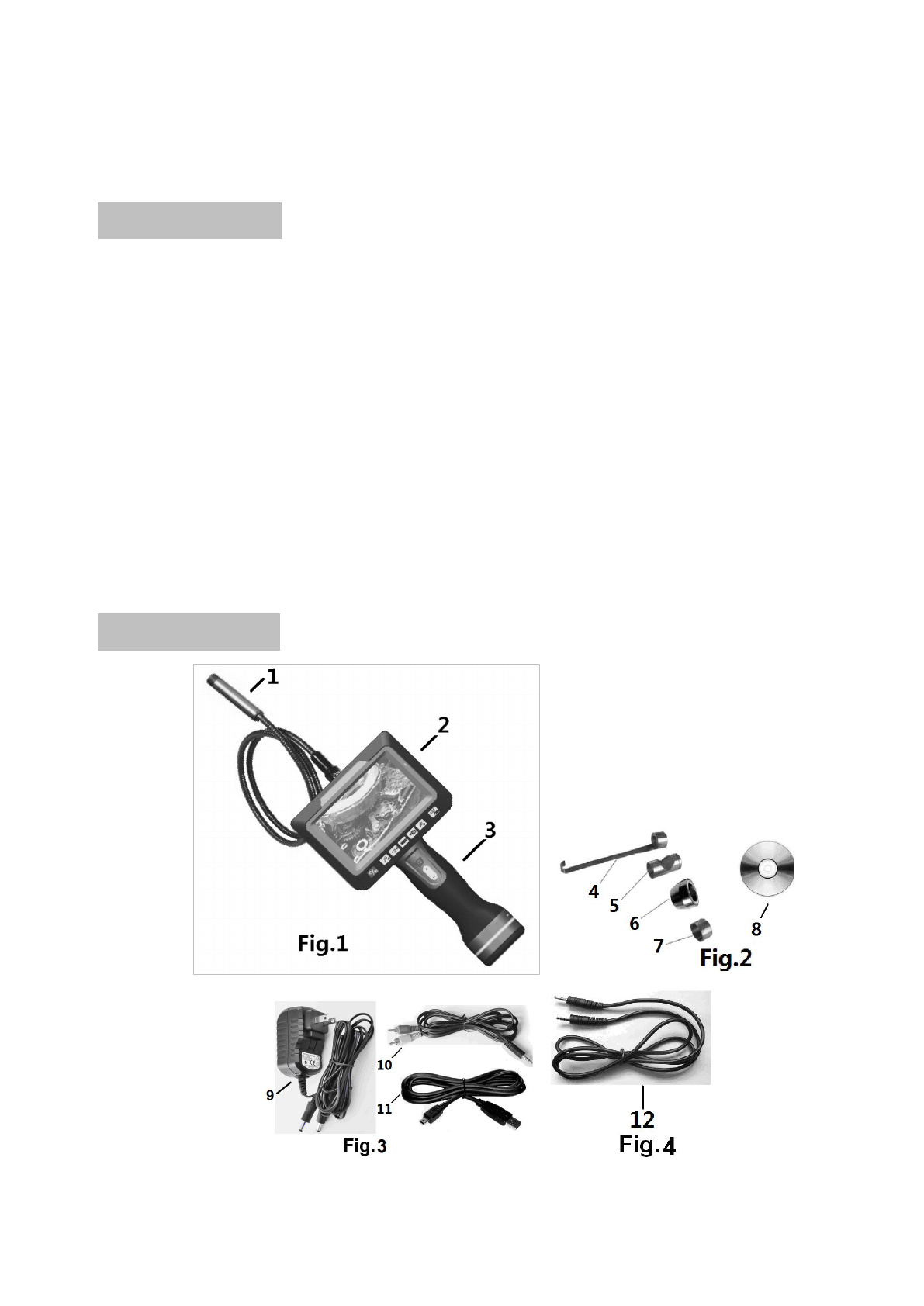
Product Configures
1.Camera and probe
3 V0.2 131015
2.LCD screen
3.Grip
4.Hook tip
5.45°Mirror tip
6.Magnetic tip
7.Protection cap
8、CD Driver
9、DC adapter
10、TV cable
11、USB cable
12、Signal cable
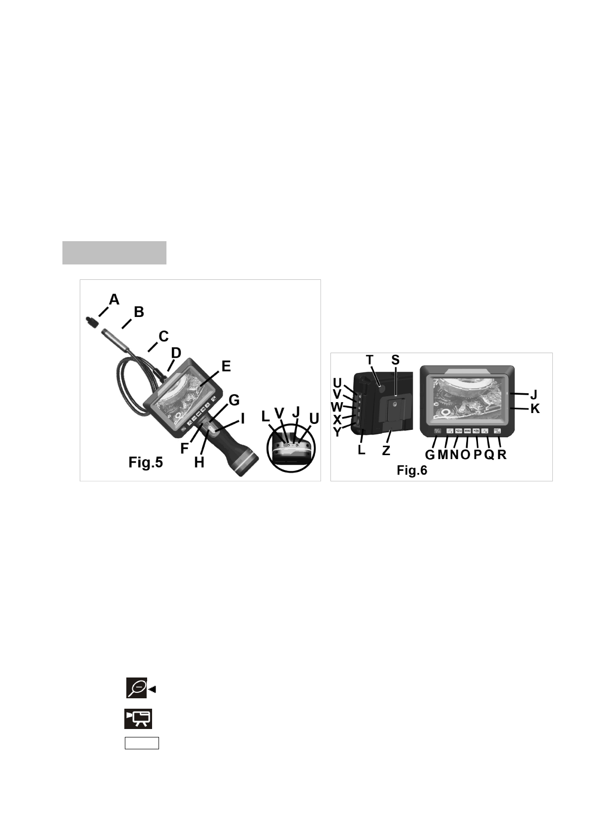
Product overview
A.Camera protection
B.Camera head
C.Probe
D.Probe connector
E.TFT screen
F.Power indication
G.Power button
H.LED brightness increase key
I.LED brightness decrease key
J.Charging light indicator
K.build-in microphone
L.Plughole protection cover
M.key——left key/zoom out
N.key——upward key/video recording key
O.MENU key——menu key
4 V0.2 131015
P.key——downward key/camera key
Q.key——right key/zoom in
R.key——screen display switch/ return key
S.Tripod nut
T.build-in microphone
U.Charging interface
V.signal interface
W.TV output socket
X.USB socket
Y.Micro SD socket
Z.reset pin hole
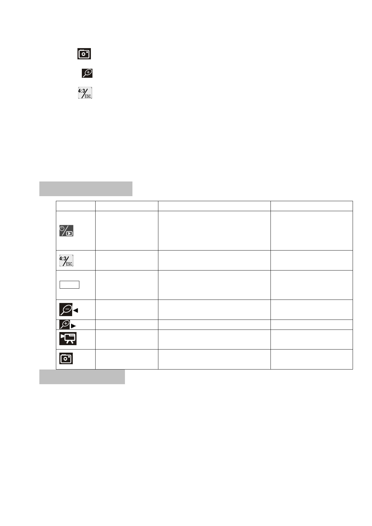
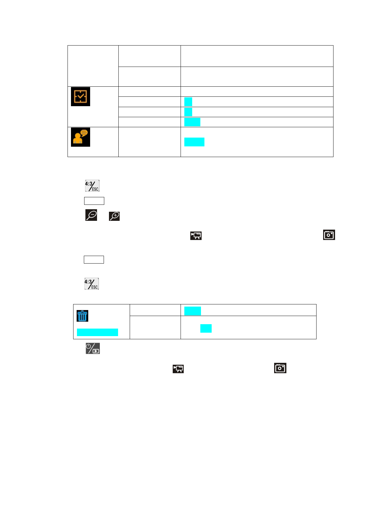
Screen Keys Instructions
Key Preview Mode Playback Mode Menu
switch to playback
mode; press and hold
for 3 seconds to power
off the unit
switch to playback mode, press and hold
for 3 seconds to power off the unit
press and hold for 3 seconds
to power off the unit
the screen display
switch as 4:3 or:16:9
browse files in grid view, press again to
browse folders
return to parent menu
MENU
switch to main menu
configures
switch to operations of current file: delete
one file, delete all files, format memory
etc.
setups and data/time
settings
image zoom out display previous picture or video clip left key
image zoom in display next picture or video clip right key
▲record video Play and pause video playback upward key/increase
data/time
▼
Take photos
manually stop video playback downward key/decrease
data/time
Operation Instructions
●Battery Charging
1、Connect the DC cable to the grip or screen.
2、Plug the AC plugs to household power outlet.
3、The LED L turns red ,means charging.
4、The LED L turns green, means fully charging
5、Pull out the AC plug of adapter.
Notes: DC adapter has double DC output plugs. If you want to charge both the grip and screen, you can
connect the two plugs to the DC port of grip and screen.
5 V0.2 131015
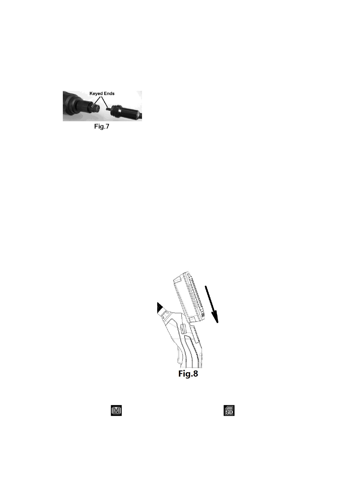
●Connect the grip unit to camera probe
The inspecting grip must be connected to the camera probe. To connect the probe, make sure the keyed
ends are properly aligned. (Fig7). Once they are aligned, finger tighten the nut.
Note: The probe can’t be connected after the unit is on. Before connecting the probe, be sure the unit
is off, in case of the current harms the unit.
●Accessories installation
The unit uses accessories for 9mm probe shown in Fig.2. Accessories and camera head are connected
using thread connection. Put on the screw thread protector when no accessory is installed to avoid damage to
the thread in daily use.
Remove the thread protector before install any accessories, then put on the accessory.
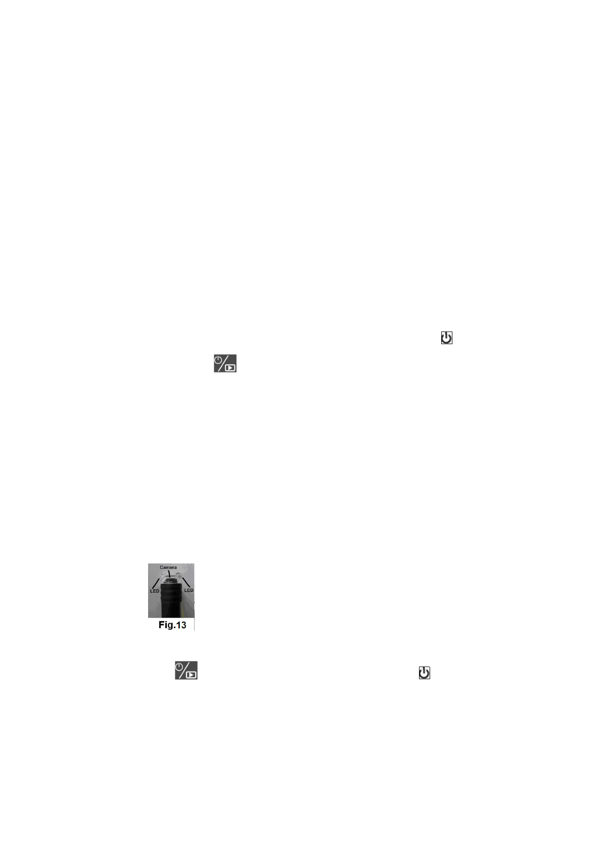
●Connect the grip to screen
The product can work both the grip detach from screen and the grip attach to screen; Slide the bottom
of slot at the back screen into the slot of grip downward until you hear the locking sound, which means
connection is finished (see Fig.8). Push the screen to the upper direction until slide away the lock buckler
to detach the screen.
●Install Micro SD card (Optional Accessory)
Photos and video clips will be stored in internal memory when a Micro SD card is not inserted and
detected, and icon will be displayed on LCD screen. Icon will be displayed when a Micro
SD card is detected, recorded photos and video clips will be stored in the Micro SD card instead of
internal memory.
6 V0.2 131015
● Connect to a PC via USB port
KC-250 has a USB 2.0 port, and can be connected to a PC.
Minimum configuration of the PC:
• P4 1.4GHz or higher CPU
• 256 MB RAM of system memory or above (recommended)
• One available USB port (USB2.0)
• Graphics Card (Must support Direct X 9.0c)
• 1GB Free HD Space
• CD-ROM Drive (For software installation)
• Microsoft Windows XP/Vista/Win7/Win8
1. Insert the included disk, find the disk folder in “My Computer”, double click the file “ScopeView” to
install control software and the driver;
2. Follow the steps, and the installer will prompt to restart the computer to complete the installation;
3. Connect the unit with a PC via USB and connect the probe on the grip. Press for 2 seconds to turn
on the grip power. Then, press to turn on the unit, and windows will detect new devices itself. Choose
install driver, a message says new device installed and ready to use will be prompted when it is done.
4. Open the software “ScopeView”, select “Instant USB Camera” under device drop list, and then click
“Connect” button to the right. The real-time image can be viewed from both the computer and the inspection
LCD screen.
5. Please refer to the software manual included in driver disk for detailed information about software
installation and operations.
6. Users are allowed to perform operations on received images using the control software, such as taking
photos and recording video clips etc.
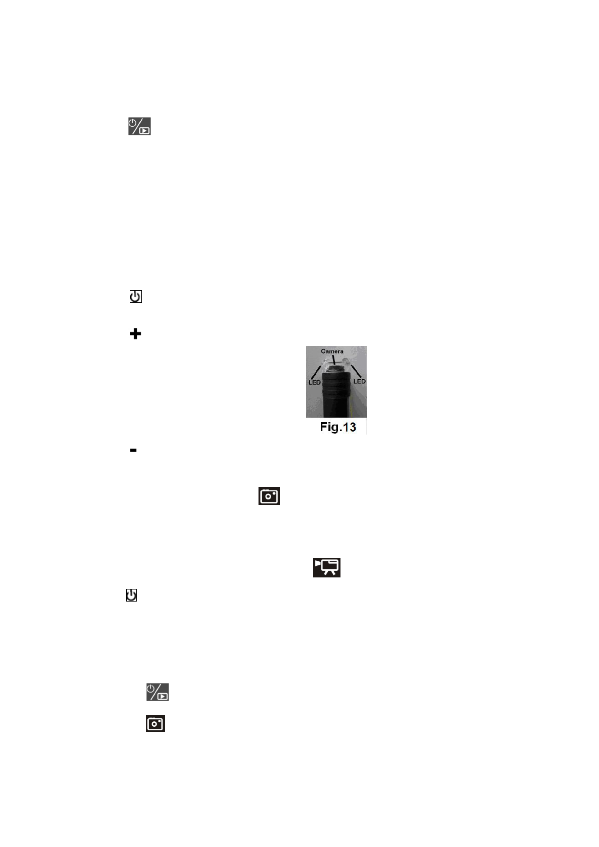
7. Press grip “+” key to increase the LED brightness (Fig.13).
8. Press grip “-” to decrease the LED brightness.
9、Press and hold for 3 seconds to power off the screen. Then press on the grip for 2 seconds to
turn off the grip power.
Note: Under USB Camera mode, do not disassemble the camera probe to avoid the current disturb the unit.
When remove the USB connection wire, the unit will turn to the LCD display mode automatically.
● Work with a computer USB Disk
7 V0.2 131015
Following below steps, users are allowed to download and upload files from the inspection unit to a
computer via USB 2.0:
1. Press on screen on the screen to turn on the screen.
2. Connect the screen to a computer using a USB cable.
3. “USB Disk” will be displayed on the LCD screen, and two portable disk (the internal memory and
external Micro SD card) will be recognized by the computer. The inspection unit now works as an U-disk.
● Video Output to TV
To view real time image from a TV, connect the VIDEO OUT port of the unit with the VIDEO IN port
of the TV using a video cable, select the right signal to review the image on TV..
●How to work
1、How to operate the grip:
a、Hold key for 2s, power on the grip, the green LED flashes ( Note: when low battery, green LED
flashes and then the unit power off automatically).
b、Press to increase the LED brightness.(Fig.13).
c、Press decrease the LED brightness.
d、Under review mode, press the shoot key once on the grip, the red LED flashes once and the screen will
take a photo ( this function is the same as the function)
e、Under review mode, continue to press the shoot key for 2s. The red LED flashes two times and the screen
enters video state. When release the key and press it again, the red LED flashes two times. At this time, the
screen stops to take video( this function is the same as the function)
f、Press key for 2 seconds. The green LED is off and the grip power turns off.
2、How to view the screen
a. Default memory is the internal memory when powered on, users can also use Micro SD card as
external memory. When a Micro SD card detected, the inspection will store files in the external
memory.
b. Press to enter preview mode in which users can preview images.
c. Press to take pictures manually (press the shoot key can do the same function), files will be
stored in internal memory or Micro SD card automatically. (Note: when Auto Capture is OFF, press
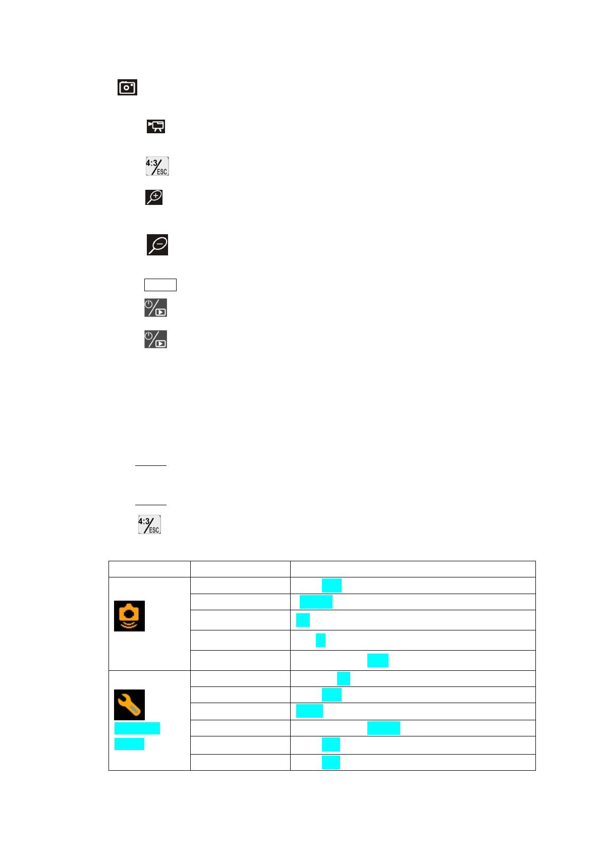
8 V0.2 131015
to take a picture; when Auto Capture is ON, unit will detect image changes and pictures will
be taken and saved automatically if any changes detected)
d. Press to record video clips (press the shoot key can do the same function), a red indicator will
be displayed on screen, and clips will be saved in internal memory or SD card.
e. Press key to show switch function. Every press, the screen will switch between 4:3 and 16:9
f. Press to zoom in from x1 to x4.0. The magnification increase by 0.5 and will be displayed on
screen.
g. Press to zoom out, the corresponding magnification will be displayed on screen; no
magnification will be displayed when the magnification is x1.
h. Press MENU to configure menu options
i. Press to enter playback mode(message will show up if no files found)
j. Press and hold for 3 seconds to turn off.
Tips: A folder named “YCKC” will be created in the internal memory or TF card in which the product
will create a sub-folder named as the current date. Videos and photos captured for the day
will be saved in this folder.
Warning: DO NOT remove the SD card while system is working (especially while recording and
transferring files with computers), doing so may result in damage to stored files and SD card.
3、Menu Configuration
a. Press MENU key in preview mode to enter menu configurations;
b. Select to be changed options using the 4 direction keys;
c. Press MENU to confirm the changed option;
d. Press to return to parent menu, and all the way back to preview mode.
e. Menu Instructions (highlighted options are factory default settings)
Menu Submenu Options
Auto Capture
Auto Capture ON;OFF
Master Ch. Photo 1;Photo 3;Movie 5s;Movie 10s
Range 1/1;1/4;1/16
Timeslot 1s;3s;5s
Sensitivity Low;Middle;High
Advanced
Setting
Movie Size QVGA;D1
File OverWrite ON;OFF
TV Output NTSC;PAL
LCD Bright LOW;NOR-;NOR;NOR+;HIGH
Format Yes;No
Set to Default Yes;No
9 V0.2 131015
Disk Information Free ****MB
Total ****MB
FW Version Ver *.**
UI *.**
Set Time/Date
Set Time/Date YY/MM/DD
Photo TimeStamp On;Off
Moive TimeStamp On;Off
Off Delay Never;5min;15min;30min
Language Select
Language Select English;Français;Español;Português;简体中文
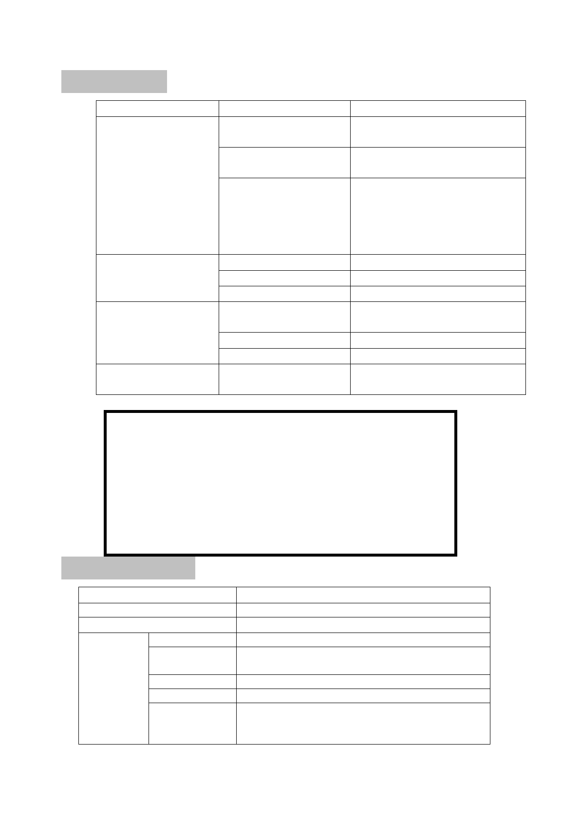
4、File Operations in Playback Mode
a. Press to browse files in grid view, press again to browse folders.
b. Press MENU to view files or folders.
c. Press or to view last or next image.
d. If the current selected file is video clip, press to play video, press again to pause, and press
to stop playback.
e. Press MENU to activate file operations, press the direction keys to perform delete single file, delete
all files and format memory etc.
f. Press to return to parent menu, and all the way back to playback mode.
g. Playback mode settings:
Playback Menu
File Delete Single;All Files In Folder;All
Format Yes;No
h. Press to go back to preview mode.
Tips: while playback video clips, press to play and pause the clip, press to stop playback.
Users can perform other operations after the playback has been stopped.
5、Connect Signal Wire to Grip and Screen
The image signal is transferred between grip and screen wirelessly. When the signal is disturbed and can’t
be received, we can connect the grip and screen with a signal wire to transfer the signal. In
wirely-transferring state, the unit will close the wireless function automatically. In this way, the image
quality will not be disturbed by environment and the resolution will be improved.
6、Applications
This product is designed for hard-to reach distance inspection. Typical applications include HVAC

10 V0.2 131015
inspection, automobile inspection, circuitry, vessel and aircraft inspection. While in operation, the product
is easy to extend ahead. If there is a distance limitation, the accessories could be applied to pick up rings
or screws on the floor.
● Operation Precautions:
a. Please read the safety instructions carefully, choose desirable work area for fear causing danger.
b. The probe is flexible to help you operate in hard-to–reach areas. Please don’t insert or bend by force..
Please do not over bend any part of the probe. Normally, the bending radius should more than 5cm to
prevent from causing permanent damage to the probe.
c. Don’t use the probe or camera head to modify surroundings, clear pathways or clogged areas. It
couldn’t be used as a fishing rod or tape.
d. The hand-held display unit is not waterproof .The camera head and its cover are waterproof, but not
acid-proof or fireproof. Don’t touch with these materials or they will ruin the camera head’s protective
plastic. Avoid immersing the camera head into corrosive, oily places or high-temperature objects.
e. Don’t place the inspection into anything or anywhere that may contain a live electrical charge. Please
check following methods to avoid injury.
For walls: For inspecting the inside walls, be sure to shut off the circuit breaker to the whole house
before using the tool.
For pipes: If you suspect a metal pipe could contain an electrical charge, have a qualified
electrician to check the pipe before using. A ground circuit, in some cases, can be
returned to the cast aluminum pipes and cause them to be charged.
For automobiles:Be sure the automobile is not running during inspection. Metal and liquid under
the hood may be hot. Don’t get oil or gas on the camera head.
Operation Notes
●Please read the manual thoroughly and make sure proper training has been complete before operating
this product.
●The green LED on the grip will flash when battery is low, eventually the grip power will power off
itself.
●The product can display real time battery capacity, “ ” and “Low battery” will flash when battery is
low, eventually the product will power off itself.
●Do not remove SD card during recording and USB connection mode.
●Don’t immerse the inspection into water, which will result in electric shock and damage.
●Only while the product is assembled well, the camera head is water-proof, but the grip and the screen
isn’t fully water-proof.
●Don’t use the product if white dew forms inside the camera head.

11 V0.2 131015
●If the tool couldn’t work well after turning it on. Please stop use and have the unit checked by a
qualified technician.
●Store idle product out of reach of children and other untrained persons. The tool is dangerous in the
hands of untrained users.
●Maintain the inspection tool with care. If the tool is dropped, check for the breakage ,which may affect
the tool’s operation. If it is damaged, have the tools serviced before using. Many accidents are caused by
poorly maintained products.
●Use only accessories that are recommended by the manufacturer for your product. Accessories are
suitable for the tool, but may become hazardous when used on another product.
●Dry your hands before turning the tool ON or OFF.
●Protect against excessive heat. The product should be kept away from heat sources, such as radiators、
heat registers、stoves or other products (including amplifiers) that produce heat. Don’t use the tool near
moving machinery or areas where the temperature exceeds 45℃.
●Please cover the camera protection while not in use.
●Store the product in ventilated and dry places.
Maintenance Instructions
●Product service must be performed only by qualified personnel. Performed by untrained personnel could
result in injury.
●When servicing the product, only use identical replacement parts. Use of authorized parts or failure to
follow maintenance instructions may create a risk of electrical shock or injury.
●Don’t attempt to disassemble the product other than the needs specified on this manual.
●Provide proper cleaning: don’t use acetone to clean the product. Gently clean the LCD with a soft dry
cloth.
●Upon completion of any service or repair, please ask the service technician to check if the tool is in
proper condition.
●Stop using the unit if it starts smoking or emitting noxious fumes.
●Please ask qualified person under the following conditions:
a. If liquid has been spilled or objects have fallen into product.
b. If product doesn’t operate normally even if you have followed the operation instructions.
c. If the product has been dropped or damaged in any way.
d. When the product exhibits a distinct change in performance.
12 V0.2 131015
Trouble Shootings
Problems Causes Solutions
Can’t charge.
Adapter didn’t connect well
with the product.
Please check and try again.
The connect or or cable is
broken.
Replace and try again.
The working temperature of
battery is so high (indication
is when plug in the adapter,
the red and green LED on at
the same time) .
Charge after the temperature is down.
The screen is on but
without image or shows
“No Signal”
1、the grip power is off Check and open the grip power
2、The probe is loosed. Check and connect again.
3、Stains on the camera head.
Check if exists stains
The product couldn’t
power on.
The circuit is in protection
status. Use adapter for charging to release.
Low energy of inside battery Use adapter for charging
Dead battery Ask a technician to replace the battery.
Unusual display or invalid
keys
Interference to the screen or
voltage fluctuation.
Please use the reposition key on the
back of screen
C a u t i o n s
●Don’t drop the product or use by force.
●Don’t disassemble the product to avoid failure.
●Don’t place the product with corrosive gas or objects.
●Don’t expose the product in vibration、high or low temperature.
●Store the product in a safe area.
●Don’t immerse the product into water, which will result in damage to product.●
Please charge the inside battery every three month if no use for long time.
Technical Specification
Name Multifunction video inspection
Model DCS500T/DCS500R
Recommended use Indoor
Standard
probe
specifications
(KC09AV4)
image sensor type
30,000 pixels CMOS image sensor
Outer diameter of
camera head
Φ9mm
Focal length 50mm
visible angle 60°
Probe length
standard flexible 1m;
2m/3m or customized (the longest length of obedient probe
is 10m and flexible probe is 40m)

13 V0.2 131015
Probe accessories magnet, hook, mirror and screw thread protector
Support
camera head
assembly
specifications
(not included)
KC12AV4
The assembly of Φ12mm camera head
KC05AV3
The assembly of Φ5.5mm flexible or obedient camera
head
KC23AV
The assembly of Φ23mm camera head checking the
probe
KC12AV5
The assembly of Φ12mm camera head without probe
The probe connection head for
choice (not included)
Used to connect the old camera head
Probe and camera head protection
IP67
Light source High lighting LED
Image display 5″TFT/LCD
Image resolution 640×480 pixels
LCD Resolution 800×480 pixels
Image zooming 4 times
TV output format NTSC/PAL
USB export mode
moveable storage mode(USB Disk)
real-time export image mode(USB Camera)
Image storage media
128MB memory
Micro SD card (Support up to 16G), the SD cardfor choice
Wireless transmission frequency 2468MHz
Wireless transmission distance Up to 10M; If no obstacles, will more than 10M
Remote control for a photo Up to 4M; If no obstacles, will more than 4M
Attachment
Adapter、TV cable、USB cable、signal cable、CD driver
Adapter
INPUT AC 100~240V(50~60Hz)
OUTPUT DC 9V 1.3A
Inside battery Polymer Lithium battery
Battery capacity Grip
7.4V/1350mAh
Screen
7.4V/1500mAh
Charging time of inside battery About 3.5 hours
Battery life >2.5 hours
Operating temperature 0℃~45℃
Operating humidity RH 5%~95% non-condensing
Storage temperature -20℃~+60℃,≤85%(w/o battery)
Dimension
Grip
280mm×138mm×71mm(w/o probe)
Screen 153.5mm×116.5mm×38mm
Weight
Grip About 353 g(w/o probe)
Screen About 428 g
Warranty
The product is warranted to be free from defects in materials and workmanship
for a period of one year from the date of purchase on the basis of providing relevant card.
Notice:
The warranty does not apply to the following conditions:
● Unauthorized disassembling the device will void the warranty.

14 V0.2 131015
●We are not responsible for any damage resulting from abrasion, water, dropping or
disassembling
Tips:Most parts of the product could be recycled, please refer to your local regulations for disposing of
them instead of throwing into the dustbin.